JP2009196040A - Robot system - Google Patents
Robot systemDownload PDFInfo
- Publication number
- JP2009196040A JP2009196040AJP2008040540AJP2008040540AJP2009196040AJP 2009196040 AJP2009196040 AJP 2009196040AJP 2008040540 AJP2008040540 AJP 2008040540AJP 2008040540 AJP2008040540 AJP 2008040540AJP 2009196040 AJP2009196040 AJP 2009196040A
- Authority
- JP
- Japan
- Prior art keywords
- unit
- robot
- hand
- pressure
- operator
- Prior art date
- Legal status (The legal status is an assumption and is not a legal conclusion. Google has not performed a legal analysis and makes no representation as to the accuracy of the status listed.)
- Pending
Links
Images


Landscapes
- Manipulator (AREA)
Abstract
Translated fromJapaneseDescription
Translated fromJapanese本発明は、ロボットシステムに関し、特にマスタ・スレーブ型のロボットを備えるロボットシステムに関する。 The present invention relates to a robot system, and more particularly to a robot system including a master / slave type robot.
電気的あるいは磁気的な作用を用いて人間と似たような動作を行う装置としてロボットがある。このようなロボットは、人間の代わりに作業を行う、又は人間の作業を補助するために利用されることが多い。ロボットに関する技術としては、例えば特許文献1に記載の技術がある。 A robot is a device that performs an action similar to that of a human by using an electrical or magnetic action. Such robots are often used to perform tasks on behalf of humans or to assist human tasks. As a technique related to the robot, for example, there is a technique described in Patent Document 1.
特許文献1に記載のロボットは、マスタ・スレーブ型のロボットを備えるロボットシステムを開示するものである。具体的には、ロボットを操作する操作者(マスタ)の手に装着される3次元操作グローブと、3次元操作グローブにより操作されるロボットアーム及びロボットハンドを持つロボット(スレーブ)とを備えるロボットシステムを開示するものである。このロボットシステムでは、ロボットアーム及びロボットハンドが操作者の腕及び手の動きを忠実に再現する。
ところで、特許文献1には、如何にしてロボットシステムを製品の生産に用いるかについての開示はない。しかしながら、特許文献1に記載のロボットシステムをセル生産方式の製品生産に用いようとした場合、様々な問題が生じる。すなわち、セル生産方式の製品生産では作業者一人が製品を組み立てるため、部品にかけるべき力も多様化するが、特許文献1に記載のロボットシステムでは、操作者による実際の物への力のかけ具合がロボットに伝わらない。従って、例えば部品を掴むときに部品に力を加え過ぎて部品が破損したり、逆に部品に加える力が足りなくて部品を落としたりするという事態が多発する。 By the way, Patent Document 1 does not disclose how to use a robot system for product production. However, when the robot system described in Patent Document 1 is used for the production of a cell production product, various problems arise. That is, in the cell production system product production, since one worker assembles the product, the force to be applied to the parts is also diversified. However, in the robot system described in Patent Document 1, how the operator applies the force to the actual thing. Is not transmitted to the robot. Therefore, for example, when a part is grasped, there are many situations in which the part is damaged due to excessive force applied to the part or the part is dropped due to insufficient force applied to the part.
そこで、本発明は、かかる問題点に鑑み、セル生産方式の製品生産に適用可能なロボットシステムを提供することを目的とする。 In view of the above problems, an object of the present invention is to provide a robot system applicable to cell production type product production.
上記目的を達成するために、本発明のロボットシステムは、物を掴むための手ユニットを有するロボットと、前記ロボットを操作する操作者の動作を検出する動作検出手段と、前記ロボットの動作を制御するロボット制御手段とを備え、前記動作検出手段は、前記操作者の手に取り付けられ、該操作者の手にかかる圧力を検出する第1圧力検出手段を有し、前記ロボット制御手段は、前記第1圧力検出手段により検出される圧力と同じ圧力が前記手ユニットにかかる状態で、前記動作検出手段により検出された動作と同じ動作を前記ロボットが行うよう前記手ユニットの動作を制御する動作制御手段を有することを特徴とする。 In order to achieve the above object, a robot system of the present invention controls a robot having a hand unit for grasping an object, an operation detecting means for detecting an operation of an operator who operates the robot, and an operation of the robot. And a robot control unit configured to include a first pressure detection unit that is attached to the operator's hand and detects a pressure applied to the operator's hand. Operation control for controlling the operation of the hand unit so that the robot performs the same operation as the operation detected by the operation detection unit in a state where the same pressure as the pressure detected by the first pressure detection unit is applied to the hand unit. It has the means.
ここで、前記手ユニットは、前記操作者の片方の手の2本の指と同じ長さを持ち、部品を把持するための2つの指状部と、前記操作者の片方の手の掌と同じ長さを持ち、前記2つの指状部が連結される掌状部とから構成され、前記第1圧力検出手段は、前記操作者の指に取り付けられ、前記動作制御手段は、前記第1圧力検出手段により検出される圧力と同じ圧力が前記指状部にかかる状態で前記手ユニットの動作を制御してもよい。 Here, the hand unit has the same length as two fingers of one hand of the operator, and has two finger portions for gripping a part, and a palm of the hand of the operator. The first pressure detection means is attached to the operator's finger, and the motion control means is the first length. You may control operation | movement of the said hand unit in the state which the same pressure as the pressure detected by a pressure detection means applies to the said finger-like part.
これによって、操作者の手にかかる圧力が検出され、ロボットの手ユニットにかかる圧力もこれと同じような圧力となるようにロボットの動作が制御される。従って、操作者による実際の物への力のかけ具合をロボットに伝えることができるので、セル生産方式の製品生産に適用可能なロボットシステムを実現することができる。 Thereby, the pressure applied to the operator's hand is detected, and the operation of the robot is controlled so that the pressure applied to the hand unit of the robot is the same pressure. Accordingly, the degree of force applied to the actual object by the operator can be transmitted to the robot, so that a robot system applicable to cell production type product production can be realized.
また、前記ロボットは、前記手ユニットに取り付けられ、該手ユニットにかかる圧力を検出する第2圧力検出手段を有し、前記ロボット制御手段は、さらに、前記第1圧力検出手段により検出される圧力と前記第2圧力検出手段により検出される圧力との差が閾値を超えているか否かを判定する判定手段と、前記圧力の差が閾値を超えていると判定されたときに前記動作検出手段により検出された動作に補正を加え、前記ロボットが補正の加えられた動作を行うよう前記手ユニットの動作を制御する補正手段とを有してもよい。 The robot has a second pressure detection unit that is attached to the hand unit and detects a pressure applied to the hand unit, and the robot control unit further includes a pressure detected by the first pressure detection unit. Determining means for determining whether or not the difference between the pressure detected by the second pressure detecting means exceeds a threshold value, and the operation detecting means when it is determined that the pressure difference exceeds the threshold value And correcting means for correcting the movement detected by the control unit and controlling the movement of the hand unit so that the robot performs the corrected movement.
また、前記動作検出手段は、さらに、前記操作者の手に取り付けられ、該操作者の手の位置を検出する第1位置検出手段を有し、前記ロボットは、さらに、前記手ユニットの位置を検出する第2位置検出手段を有し、前記判定手段は、前記第1位置検出手段により検出される位置と前記第2位置検出手段により検出される位置との差が閾値を超えているか否かを判定し、前記補正手段は、前記位置の差が閾値を超えていると判定されたときに前記動作検出手段により検出された動作に補正を加え、前記ロボットが補正の加えられた動作を行うよう前記手ユニットの動作を制御してもよい。 The motion detection means further includes a first position detection means attached to the operator's hand for detecting the position of the operator's hand, and the robot further determines the position of the hand unit. A second position detecting means for detecting, wherein the determining means determines whether or not a difference between a position detected by the first position detecting means and a position detected by the second position detecting means exceeds a threshold value; The correction means corrects the motion detected by the motion detection means when it is determined that the position difference exceeds a threshold value, and the robot performs the corrected motion. The operation of the hand unit may be controlled.
このとき、前記補正手段は、前記圧力又は位置の差が閾値を超えていると判定されたときに、前記圧力又は位置の差が小さくなるよう補正を加えることが好ましい。 At this time, it is preferable that the correction unit performs correction so that the difference in pressure or position is reduced when it is determined that the difference in pressure or position exceeds a threshold value.
これによって、ロボットが操作者と同じ動作を行っていないことを検知し、それに対応することができるので、高確率でロボットの作業ミスを回避し、確実に製品を組み立てることが可能なロボットシステムを実現することができる。 As a result, it is possible to detect that the robot is not performing the same operation as the operator, and to respond to it. Therefore, a robot system that can avoid mistakes of the robot work with high probability and can assemble products reliably. Can be realized.
また、本発明は、ロボットを操作する操作者の動作を検出する動作検出ステップと、前記ロボットの動作を制御するロボット制御ステップとを含み、前記動作検出ステップでは、前記操作者の手にかかる圧力を検出し、前記ロボット制御ステップでは、前記動作検出ステップにより検出される圧力と同じ圧力が前記ロボットの物を掴むための手ユニットにかかる状態で、前記動作検出ステップにより検出された動作と同じ動作を前記ロボットが行うよう前記手ユニットの動作を制御することを特徴とするロボット制御方法とすることもできる。 Further, the present invention includes a motion detection step for detecting a motion of an operator who operates the robot, and a robot control step for controlling the motion of the robot. In the motion detection step, a pressure applied to the hand of the operator In the robot control step, the same operation as the operation detected in the operation detection step is performed in a state where the same pressure as the pressure detected in the operation detection step is applied to the hand unit for grasping the object of the robot. The robot control method may be characterized in that the operation of the hand unit is controlled so that the robot performs the following.
これによって、セル生産方式の製品生産に適用可能なロボット制御方法を実現できる。
また、本発明は、ロボットを用いて部品を組み合わせ製品の生産を行う製品生産システムであって、物を掴むための手ユニットを有するロボットと、前記ロボットを操作する操作者の動作を検出する動作検出手段と、前記ロボットの動作を制御するロボット制御手段と、前記操作者及びロボットのそれぞれに同一種の部品を供給する部品供給手段とを備え、前記動作検出手段は、前記操作者の手に取り付けられ、該操作者の手にかかる圧力を検出する第1圧力検出手段を有し、前記ロボット制御手段は、前記第1圧力検出手段により検出される圧力と同じ圧力が前記手ユニットにかかる状態で、前記動作検出手段により検出された動作と同じ動作を前記ロボットが行うよう前記手ユニットの動作を制御する動作制御手段を有し、前記部品供給手段は、前記手ユニットと部品との位置関係が前記操作者の手と部品との位置関係と同じになるよう部品を供給することを特徴とする製品生産システムとすることもできる。Thereby, it is possible to realize a robot control method applicable to cell production type product production.
Further, the present invention is a product production system for producing a product by combining parts using a robot, and an operation for detecting an operation of a robot having a hand unit for grasping an object and an operator operating the robot Detection means, robot control means for controlling the operation of the robot, and parts supply means for supplying parts of the same type to the operator and the robot, respectively. A first pressure detecting means that is attached and detects the pressure applied to the hand of the operator, wherein the robot control means is in a state where the same pressure as the pressure detected by the first pressure detecting means is applied to the hand unit; And the operation of the hand unit is controlled so that the robot performs the same operation as the operation detected by the operation detecting unit. Stage may be a production system, wherein a positional relationship between the hand unit and component supply parts to be the same as the positional relationship between the operator's hand and parts.
これによって、セル生産方式において操作者の動きに連動してロボットに同一の作業を行わせる形で製品を生産する。従って、生産すべき製品の種類が変わった場合でも生産プログラム等の生産条件を変更する作業が必要ないので、安価で容易に複数種の製品の生産をおこなうことができる。 As a result, in the cell production method, the product is produced in such a manner that the robot performs the same work in conjunction with the movement of the operator. Therefore, even if the type of product to be produced changes, there is no need to change the production conditions such as a production program, so that it is possible to easily produce a plurality of types of products at low cost.
また、製品生産に複雑な構造を必要としないマスタ・スレーブ型のロボットが用いられるため、容易に製品の大量生産をおこなうことができる。 In addition, since a master / slave robot that does not require a complicated structure for product production is used, mass production of products can be easily performed.
また、本発明は、ロボットを用いて部品を組み合わせ製品の生産を行う製品生産方法であって、ロボットを操作する操作者の動作を検出する動作検出ステップと、前記ロボットの動作を制御するロボット制御ステップと、前記操作者及びロボットのそれぞれに同一種の部品を供給する供給ステップとを含み、前記動作検出ステップでは、前記操作者の手にかかる圧力を検出し、前記ロボット制御ステップでは、前記動作検出ステップにより検出される圧力と同じ圧力が前記ロボットの物を掴むための手ユニットにかかる状態で、前記動作検出ステップにより検出された動作と同じ動作を前記ロボットが行うよう前記手ユニットの動作を制御し、前記供給ステップでは、前記手ユニットと部品との位置関係が前記操作者の手と部品との位置関係と同じになるよう部品を供給することを特徴とする製品生産方法とすることもできる。 The present invention also relates to a product production method for producing a product by combining parts using a robot, the motion detection step for detecting the motion of an operator who operates the robot, and the robot control for controlling the motion of the robot. And a supply step of supplying parts of the same type to each of the operator and the robot. In the motion detection step, pressure applied to the hand of the operator is detected. In the robot control step, the motion is performed. The operation of the hand unit is performed so that the robot performs the same operation as the operation detected by the operation detection step in a state where the same pressure as the pressure detected by the detection step is applied to the hand unit for grasping the object of the robot. In the supplying step, the positional relationship between the hand unit and the component is the positional relationship between the operator's hand and the component. It may be a product produced wherein the supplying part to be the same.
これによって、安価で容易に複数種の製品の生産をおこなうことが可能な製品生産方法を実現できる。 As a result, a product production method capable of producing a plurality of types of products at low cost and easily can be realized.
本発明によれば、セル生産方式の製品生産に適用可能なロボットシステムを実現することができる。 ADVANTAGE OF THE INVENTION According to this invention, the robot system applicable to the product production of a cell production system is realizable.
以下、本発明の実施の形態における製品生産システムについて、図面を参照しながら説明する。 Hereinafter, a product production system according to an embodiment of the present invention will be described with reference to the drawings.
図1は、本実施の形態の製品生産システムの概略構成を示す図である。
本実施の形態の製品生産システムは、複数のロボットを用いて部品を組み合わせセル生産方式の製品生産を行うシステムであって、ロボットシステム10及び部品供給部20から構成される。FIG. 1 is a diagram showing a schematic configuration of a product production system according to the present embodiment.
The product production system according to the present embodiment is a system that performs product production using a cell production method by combining parts using a plurality of robots, and includes a
ロボットシステム10は、ロボットを操作する操作者(作業者)11が行う製品の組立作業に協調して操作者11と同様の作業を行うマスタ・スレーブ型のロボット120を複数備える。各ロボット120の周囲には、操作者11が作業を行う環境と全く同じ環境が作られている。製品の組立作業とは、具体的に、部品の基板への実装あるいは装着、及び部品の組立等一般の組立作業である。 The
部品供給部20は、操作者11及び複数のロボット120のそれぞれに同一種の部品を供給する。部品供給部20は、操作者11及び複数のロボット120のそれぞれに設けられ、ロボット120の物を掴むための手ユニットと部品との位置関係と、操作者11の手と部品との位置関係とが同じになるように部品を供給する。 The
図2は、ロボットシステム10の概略構成を示す図である。
ロボットシステム10は、検出部110、複数のロボット120及びそれに対応する複数のロボット制御部130から構成される。FIG. 2 is a diagram illustrating a schematic configuration of the
The
検出部110は、操作者11の手に取り付けられ、操作者11の手及び腕の動作を検出する。ロボット制御部130は、対応するロボット120が検出部110により検出された動作と同一の動作を操作者11と同時に行うように、ロボット120の動作を制御する。 The
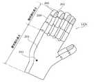
図3は、検出部110を構成するグローブの詳細な構成(片方のグローブの詳細な構成)を示す図である。 FIG. 3 is a diagram showing a detailed configuration of a glove constituting the detection unit 110 (a detailed configuration of one glove).
検出部110は、操作者11の手に装着され、操作者11の手の位置や操作者11の手にかかる圧力(負荷)を検出する一対のグローブ110aから構成される。グローブ110aには、第1圧力検出部111、指曲げ検出部112、第1位置方向検出部113及びこれらとロボット制御部130とを接続する配線115が埋め込まれている。 The
第1圧力検出部111は、例えば圧力センサ等であり、操作者11の指先の表面に位置し、作業に際して手で部品を掴むとき等の物と接するときに操作者11の指先にかかる圧力を検出する。 The first
第1位置方向検出部113は、例えば3次元位置方向センサであり、操作者11の手首付近に位置し、該操作者11の手の位置及び手首の角度を検出する。手首の角度検出には、例えばジャイロセンサ等が用いられる。 The first position /
指曲げ検出部112は、操作者11の各指の関節毎に設けられ、各指の曲げ量を検出する。 The finger
第1圧力検出部111、指曲げ検出部112及び第1位置方向検出部113による圧力及び角度の検出結果は、ロボット120の動作の指令値としてリアルタイムにシリアル通信でロボット制御部130に送られる。ロボット制御部130は、送られてきた指令値を基にロボット120に操作者11と同じ動作を行わせる。 The pressure and angle detection results by the first
図4は、ロボット120の詳細な構成及びその駆動機構を示す図である。
ロボット120は、操作者11の腕と手の動きを忠実に再現する6軸ロボットであり、胴ユニット121、頭部ユニット122及び2つの腕ユニット123から構成される。FIG. 4 is a diagram showing a detailed configuration of the
The
胴ユニット121は、操作者11の胴に対応して設けられたユニットである。胴ユニット121は、モータM9を駆動することにより、1つの軸の回りに回転させることができるようにされている。胴ユニット121には、モータM1〜9及び認識カメラ122a等の駆動を制御する制御部が配設されている。 The
頭部ユニット122は、操作者11の頭に対応して設けられたユニットであり、胴ユニット121の上部に連結される。頭部ユニット122は、モータM1及びM2をそれぞれ駆動することにより、直交する2つの軸の回りに独立に回転させることができるようにされている。頭部ユニット122には、操作者11の目に対応して、ロボット120の周囲を撮像する上下左右動作可能なCCDあるいはMOS型の複眼の認識カメラ122aが配設されている。認識カメラ122aの焦点は認識対象の位置にあわせられ、例えばロボット120の作業状況等が確認される。 The
各腕ユニット123は、上腕ユニット123a、前腕ユニット123b及び手ユニット123cから構成され、胴ユニット121の両側部に連結される。 Each
上腕ユニット123aは、操作者11の上腕に対応して設けられたユニットであり、前腕ユニット123bと連結され前腕ユニット123bを所定の位置に移動させる。上腕ユニット123aは、モータM3及びM4をそれぞれ駆動することにより、直交する2つの軸の回りに独立に回転させることができるようにされている。上腕ユニット123aは、操作者11の片腕の上腕と略同じ長さを持つ。 The
前腕ユニット123bは、操作者11の前腕に対応して設けられたユニットであり、手ユニット123c及び上腕ユニット123aと連結され手ユニット123cを所定の位置に移動させる。前腕ユニット123bは、モータM5及びM6をそれぞれ駆動することにより、直交する2つの軸の回りに独立に回転させることができるようにされている。前腕ユニット123bは、操作者11の片腕の前腕と略同じ長さを持ち、手ユニット123cの掌状部が連結される。 The
手ユニット123cは、操作者11の手に対応して設けられた、部品を掴むためのユニットである。手ユニット123cは、モータM7及びM8を駆動することにより、直交する2つの軸の回りに独立に回転させることができるようにされている。手ユニット123cの表面は、弾性体により構成されている。 The
図5は、手ユニット123cの斜視図である。
手ユニット123cは、操作者11の片手の5本の指と略同じ長さを持ち、部品を把持するための5本の指状部200と、操作者11の片手の掌と略同じ長さを持ち、5本の指状部200が連結される掌状部201とから構成される。手ユニット123cには、第2圧力検出部202及び第2位置方向検出部203が取り付けられている。指状部200の関節部204にはモータが取り付けられており、指状部200は関節部204毎に曲がるように構成されている。FIG. 5 is a perspective view of the
The
第2圧力検出部202は、手ユニット123cの各指状部200の先で部品と接する部分に取り付けられ、手ユニット123cが部品を掴むとき等の物と接するときに手ユニット123cの各指状部200の先にかかる圧力を検出する。 The second
第2位置方向検出部203は、手ユニット123cの位置、具体的には手ユニット123cの掌状部201の位置と、前腕ユニット123b及び手ユニット123cがなす角度とを検出する。 The second position /
図6は、ロボットシステム10の機能的な構成を示すブロック図である。
ロボット制御部130は、動作指令生成部131、判定部132及び補正部133から構成される。FIG. 6 is a block diagram illustrating a functional configuration of the
The
動作指令生成部131は、本発明の動作制御手段の一例であり、検出部110の検出結果に基づいてロボット120に対する動作指令を生成し、この動作指令により手ユニット123cの動作を制御する。具体的に、動作指令生成部131は、第1圧力検出部111により検出される圧力と同じ圧力が手ユニット123cの各指状部200の先にかかる状態で、指曲げ検出部112及び第1位置方向検出部113により検出された操作者11の動作と同じ動作をロボット120が行うよう手ユニット123cを動作させる動作指令を生成し、この動作指令により手ユニット123cの動作を制御する。すなわち、ロボット制御部130には、操作者11が装着した検出部110から得られる手の位置及び手首の角度になるように、ロボット制御部130に指令データを送り、操作者11が作業を行っている位置に基づき、ロボット120を正確にロボット120が動作している作業環境の中で、動作させる。また、操作者11がグローブ110aを使用して作業を行う場合には、グローブ110aから検出される圧力を、ロボット制御部130に送り、そのデータを指令値にして、ロボット制御部130は、第2圧力検出部202から検出される圧力が前記指令値に合致するように制御を行っている。しかしながら、ロボット制御部130が操作者11の動作で検出される手の位置及び手首の角度や各指の曲げ量やグローブ110aで検出できる圧力に近づくように制御を行っても、実際のロボット120の動作、具体的には挿入作業や組立作業等のためのロボット120の動作において、位置ズレや抉れ等によって、ロボット120の手の位置及び手首の角度や手ユニット123cで検出される圧力が、操作者11の手の位置や手首の角度、グローブ110aで検出される圧力と異なった値になる場合があり、そのような場合には、補正された動作を行うものとし、ロボット120を操作者11の作業に近づけるように動作を行う。 The operation
判定部132は、検出部110の第1圧力検出部111により検出される圧力と、ロボット120の第2圧力検出部202により検出される圧力との差が閾値を超えているか否かを判定する。同様に、判定部132は、検出部110の第1位置方向検出部113により検出される位置と、ロボット120の第2位置方向検出部203により検出される位置との差が閾値を超えているか否かを判定する。さらに、判定部132は、第1位置方向検出部113により検出される位置が所定の領域内にあるか否かを判定する。 The
補正部133は、判定部132により圧力の差又は位置の差が閾値を超えていると判定されたとき、圧力又は位置の差が小さくなるよう動作指令生成部131により生成された動作指令を補正して新たな動作指令を生成し、新たな動作指令により手ユニット123cの動作を制御する。すなわち、補正部133は、検出部110により検出された操作者11の動作に補正を加え、ロボット120が補正の加えられた動作を行うよう手ユニット123cの動作を制御する。 The
次に、上記構成を有するロボットシステム10の動作について説明する。図7は、同ロボットシステム10の動作を示すフローチャートである。 Next, the operation of the
まず、製品の組立作業を開始するに際して操作者11は所定の棒を握る等により操作者11の手が動作の原点にあることをロボット120に教示する。 First, when starting the assembly work of the product, the
次に、検出部110は、部品供給部20により供給された部品を用いて製品の組立作業を行うに際して操作者11の手がどの位置にあり、手首がどれぐらい曲がっているのかを第1位置方向検出部113により検出させる(ステップS301)。 Next, the
次に、検出部110は、製品の組立作業を行うに際して操作者11の指がどれぐらい曲がっているのかを指曲げ検出部112により検出させる(ステップS302)。 Next, the
次に、検出部110は、操作者11が製品の組立作業を行うに際して操作者11の指先が感じている圧力を第1圧力検出部111により検出させる(ステップS303)。 Next, the
次に、検出部110は、検出された操作者11の手の位置、手首の角度、指の曲げ量及び指先にかかっている圧力を示す操作者検出データをロボット制御部130に送信する(ステップS304)。 Next, the
ここで、操作者11が部品を落とす等の不測の問題が発生した場合、操作者11は例えば検出部110に設けられたリセットボタンを押し、操作者検出データがロボット制御部130に送信されないようにし、ロボット120を動作の原点に戻させる。そして、部品を拾い上げる等し、発生した問題を解決した後、操作者11の手が動作の原点にあることをロボット120に教示し、作業を再開する。 Here, when an unexpected problem such as the
次に、ロボット制御部130は、送信された操作者検出データに示される操作者11の手の位置が所定の領域内にあるか否かを判定部132により判定させる(ステップS305)。具体的に、ロボット制御部130は、操作者11の手の位置が製品の組立作業を行う環境内にあるか否かを判定させる。 Next, the
次に、ロボット制御部130は、判定部132により操作者11の手の位置が所定の領域内にあると判定された場合(ステップS305でYes)、送信された操作者検出データに基づいてロボット120に対する動作指令を動作指令生成部131に生成させる(ステップS306)。具体的に、ロボット制御部130は、第1圧力検出部111により検出される圧力と同じ圧力が手ユニット123cの各指状部200の先にかかる状態で、指曲げ検出部112及び第1位置方向検出部113により検出された操作者11の動作と同じ動作をロボット120が行うよう手ユニット123cを動作させる動作指令を生成させる。 Next, when the
次に、ロボット制御部130は、動作指令生成部131により生成された動作指令をロボット120に送信する(ステップS307)。 Next, the
次に、ロボット120は、送信された動作指令に従って各モータを駆動し、操作者11の手及び腕の動作を再現する(ステップS308)。具体的に、ロボット120は、操作者11の手にかかる圧力と同じ圧力が手ユニット123cにかかる状態で、手ユニット123cを操作者11の手の位置と同じ位置に移動させ、前腕ユニット123b及び手ユニット123cがなす角度を操作者11の手首の角度と同じとし、指状部200の関節部204の曲げ角度を操作者11の指の関節の曲げ角度と同じとする。 Next, the
次に、ロボット120は、ロボット120の手ユニット123cが実際どの位置にあるかを第2位置方向検出部203により検出させる(ステップS309)。 Next, the
次に、ロボット120は、ロボット120の手ユニット123cの指状部200の先が実際感じている圧力を第2圧力検出部202により検出させる(ステップS310)。 Next, the
次に、ロボット120は、検出されたロボット120の手ユニット123cの位置及び指状部200の先にかかる圧力を示すロボット検出データをロボット制御部130に送信する(ステップS311)。 Next, the
次に、ロボット制御部130は、送信された操作者検出データに示される位置とロボット検出データに示される位置との差を導出し、導出された位置の差が閾値を超えているか否かを判定部132により判定させる。同様に、ロボット制御部130は、送信された操作者検出データに示される圧力とロボット検出データに示される圧力との差を導出し、導出された圧力の差が閾値を超えているか否かを判定部132により判定させる(ステップS312)。 Next, the
次に、ロボット制御部130は、判定部132により位置又は圧力の差が閾値を超えていると判定された場合(ステップS312でYes)、動作指令生成部131により生成された動作指令を補正部133により補正させ、新たな動作指令を生成させる(ステップS313)。具体的に、ロボット制御部130は、操作者11の動作と異なる所定の動作を行うように指示する動作指令、つまり操作者検出データに示される圧力とロボット検出データに示される圧力との差、又は操作者検出データに示される位置とロボット検出データに示される位置との差が小さくなる動作を行うように指示する動作指令を生成させる。 Next, when the
ここで、圧力の差又は位置の差が小さくなる動作とは、例えば、ロボット120が既に行っている動作(検出部110により検出された操作者11の動作と同一の動作)に、腕ユニット123(手ユニット123c)を所定の方向に少しだけ動かすという所定の動作を加えた動作である。操作者11が部品又はその一部を穴に入れるという動作を行っており、ロボット120が操作者11と同じように部品又はその一部を穴に入れることができない場合、判定部132により位置又は圧力の差が閾値を超えていると判定される。しかし、ロボット120の腕ユニット123(手ユニット123c)を所定の方向に動かすという動作を加えることにより、ロボット120は操作者11と同じように部品又はその一部を穴に入れることができる。 Here, the operation in which the pressure difference or the position difference is reduced is, for example, an operation already performed by the robot 120 (the same operation as the operation of the
次に、ロボット制御部130は、補正部133により生成された新たな動作指令をロボット120に送信する(ステップS314)。 Next, the
最後に、ロボット120は、送信された動作指令に従って各モータを駆動し、操作者11の動作と異なる補正された動作を行う(ステップS315)。 Finally, the
以上のように本実施の形態のロボットシステム10によれば、製品の組立作業を行うに際して操作者11の指先にかかる圧力が検出され、ロボット120の手ユニット123cの指状部200の先もこれと同じような圧力となるようにロボット120の動作が制御される。従って、操作者11による実際の物への力のかけ具合をロボット120に伝えることができ、例えば部品を掴むときに部品に力を加え過ぎて部品が破損したり、逆に部品に加える力が足りなくて部品を落としたりするという事態等を回避することができる。その結果、様々な問題を発生させること無くセル生産方式の製品生産に適用可能なロボットシステムを実現することができる。 As described above, according to the
また、本実施の形態のロボットシステム10によれば、ロボット制御部130は、操作者検出データに示される位置とロボット検出データに示される位置との差、又は操作者検出データに示される圧力とロボット検出データに示される圧力との差が閾値を超えていると判定された場合、自立的に動作指令を補正して操作者11と異なる動作をロボット120に行わせる。従って、ロボット120が操作者11と同じ動作を行っていないことを検知して、それに対応することができるので、高確率でロボット120の作業ミスを回避し、製品を確実に組み立てることが可能なロボットシステムを実現することができる。 Further, according to the
また、本実施の形態の製品生産システムによれば、セル生産方式においてマスタとしての操作者11の動きに連動して複数のマスタ・スレーブ型のロボット120に同一の作業を同時に行わせる形で製品が生産される。従って、生産すべき製品の種類が変わった場合でも生産プログラム等の生産条件を変化させる作業が必要ないので、安価で容易に複数種の製品の生産をおこなうことができる。 Further, according to the product production system of the present embodiment, in the cell production method, the product is obtained by causing the plurality of master /
また、本実施の形態の製品生産システムによれば、製品生産に複雑な構造を必要としないマスタ・スレーブ型のロボット120が用いられる。従って、容易に製品の大量生産をおこなうことができる。実際の動作の中では、操作者11をマスタにして、スレーブであるロボット120を複数台設けることで、生産の作業性も大幅に向上させることができ、また従来のスレーブとしてのロボットに対する複雑な教示作業も必要ないので、安定した組立作業等を行うことができる。 Further, according to the product production system of the present embodiment, the master /
以上、本発明のロボットシステムについて、実施の形態に基づいて説明したが、本発明は、この実施の形態に限定されるものではない。本発明の要旨を逸脱しない範囲内で当業者が思いつく各種変形を施したものも本発明の範囲内に含まれる。 While the robot system of the present invention has been described based on the embodiment, the present invention is not limited to this embodiment. The present invention includes various modifications made by those skilled in the art without departing from the scope of the present invention.
例えば、上記実施の形態において、第2圧力検出部及び第2位置方向検出部はロボットに設けられるとした。しかし、ロボットとは別の場所に第2圧力検出部及び第2位置方向検出部が設けられてもよい。例えば、ロボットの作業環境の中に第2圧力検出部及び第2位置方向検出部が設けられてもよい。 For example, in the above embodiment, the second pressure detection unit and the second position / direction detection unit are provided in the robot. However, the second pressure detection unit and the second position / direction detection unit may be provided in a place different from the robot. For example, a second pressure detection unit and a second position / direction detection unit may be provided in the work environment of the robot.
また、上記実施の形態において、判定部は位置又は圧力の差が閾値を超えているか否かを判定するとした。しかし、判定部は、検出部の第1位置方向検出部により検出される角度と、ロボットの第2位置方向検出部により検出される角度との差が閾値を超えているか否かを判定してもよい。この場合、補正部は、判定部により角度の差が閾値を超えていると判定されたとき、角度の差が小さくなるよう動作指令生成部により生成された動作指令を補正して新たな動作指令を生成し、新たな動作指令により手ユニットの動作を制御する。 In the above embodiment, the determination unit determines whether or not the difference in position or pressure exceeds a threshold value. However, the determination unit determines whether or not the difference between the angle detected by the first position direction detection unit of the detection unit and the angle detected by the second position direction detection unit of the robot exceeds a threshold value. Also good. In this case, when the determination unit determines that the angle difference exceeds the threshold, the correction unit corrects the operation command generated by the operation command generation unit so as to reduce the angle difference, and creates a new operation command. And the operation of the hand unit is controlled by a new operation command.
また、上記実施の形態において、ロボットの手ユニットには5本の指状部が設けられるとしたが、部品を把持するための少なくとも2本の指状部が設けられればこれに限られず、例えば3本又は4本の指状部しか設けられなくてもよいし、6本の指状部が設けられてもよい。 In the above embodiment, the robot's hand unit is provided with five finger-like parts. However, the present invention is not limited to this, as long as at least two finger-like parts for gripping parts are provided. Only three or four fingers may be provided, or six fingers may be provided.
また、上記実施の形態において、ロボットは6軸ロボットであるとしたが、これに限られず、例えばロボットは4軸、5軸又は7軸ロボットであってもよい。 In the above embodiment, the robot is a 6-axis robot. However, the present invention is not limited to this. For example, the robot may be a 4-axis, 5-axis or 7-axis robot.
また、上記実施の形態において、第1圧力検出部、指曲げ検出部及び第1位置方向検出部はグローブに取り付けられるとしたが、図8に示されるように、それぞれ個別に操作者の手に取り付けられてもよい。 In the above embodiment, the first pressure detection unit, the finger bending detection unit, and the first position / direction detection unit are attached to the glove. However, as shown in FIG. It may be attached.
また、上記実施の形態において、判定部により位置又は圧力の差が閾値を超えていると判定されたとき、補正部は圧力の差又は位置の差が小さくなる動作を行うように指示する動作指令を生成するとしたが、補正部はロボットの動作を停止するように指示する動作指令を生成してもよい。 In the above embodiment, when the determination unit determines that the position or pressure difference exceeds the threshold value, the correction unit instructs to perform an operation to reduce the pressure difference or the position difference. However, the correction unit may generate an operation command that instructs to stop the operation of the robot.
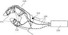
さらに、上記実施の形態において、ロボット120及び検出部110を図9に示すような形態としてもよい。すなわち、腕ユニット123と、腕ユニット123を支持するために作業台に設けられた支持棒140とからロボット120を構成し、グローブ110aと、第2位置方向検出部141(本発明の第3位置検出手段の一例)とから検出部110を構成してもよい。この場合、腕ユニット123は、第1腕ユニット123d、第2腕ユニット123e、第3腕ユニット123f及び手ユニット123cから構成される。第1腕ユニット123d、第2腕ユニット123e及び第3腕ユニット123fは互いに連結され、その一端が支持棒140と連結され他端が手ユニット123cと連結されて、手ユニット123cを所定の位置に移動させる。一方、第2位置方向検出部141は、互いに連結された第1腕ユニット141d、第2腕ユニット141e及び第3腕ユニット141fと、それらを支持するために作業台に設けられた支持棒143とから構成される。検出部110の第1腕ユニット141d、第2腕ユニット141e及び第3腕ユニット141fは、それぞれロボット120の第1腕ユニット123d、第2腕ユニット123e及び第3腕ユニット123fと略同じ形態(長さ及び形状等)を有し、その一端はグローブ110aに連結され、他端は支持棒143に連結される。検出部110の第1腕ユニット141d、第2腕ユニット141e及び第3腕ユニット141fには、各腕ユニットの動作角度を検出できるセンサが設けられており、自身の形態(位置及び角度等)が検出される。これによって、操作者11の手の位置及び手首の角度が検出される。 Furthermore, in the above embodiment, the
図9に示すロボットシステムにおいては、操作者11はグローブ110aを装着した状態で、組立作業等の作業が行われる。操作者11の第2位置方向検出部141の重量は極めて軽く、操作者11は、グローブ110aを装着して作業を行った場合においても、その作業は第2位置方向検出部141の影響を何ら受けない。ロボット120の動作は、第2位置方向検出部141から検出される各センサのデータに基づき、第2位置方向検出部141により検出される位置と同じ位置に第1腕ユニット123d、第2腕ユニット123e及び第3腕ユニット123fのそれぞれを移動させるように動作指令生成部で腕ユニット123の動作を制御し、ロボット120の動作を忠実に制御することで行われる。第2位置方向検出部141を構成する第1腕ユニット141d、第2腕ユニット141e及び第3腕ユニット141fの形態を、ロボット120を構成する第1腕ユニット123d、第2腕ユニット123e及び第3腕ユニット123fで再現することにより、操作者11の手の位置及び手首の角度をロボット120の手ユニット123cで再現するので、操作者11の作業動作をさらに確実に再現でき、操作者11の作業に従う安定した動作をロボット120に行わせることができる。また、第2位置方向検出部141がグローブ110aとは別に設けられるため、グローブ110aに第1位置方向検出部113を設けなくても、正確な操作者11の作業位置を検出することができる。以上のように、ロボット120の腕ユニット123と同等の軽量化した第1腕ユニット141d、第2腕ユニット141e及び第3腕ユニット141fを用いることで、操作者11の動作位置を正確に検出することができ、操作者11の動作をより安定してロボット120に再現させることができ、その効果は絶大なるものがある。 In the robot system shown in FIG. 9, the
また、上記実施の形態において、操作者11の手が動作の原点にあることをロボットに教示する原点教示装置として所定の棒を例示した。しかし、原点教示装置は、図9に示すように、操作者11の手型がとられた治具144であってもよい。この場合には、操作者11の手が板の手型の上に置かれたときに原点が教示される。 Further, in the above embodiment, the predetermined rod is exemplified as the origin teaching device for teaching the robot that the hand of the
本発明は、ロボットシステムに利用でき、特にマスタ・スレーブ型のロボットを用いたセル生産方式の製品生産等に利用することができる。 The present invention can be used for a robot system, and in particular, can be used for production of a cell production system product using a master / slave type robot.
10 ロボットシステム
11 操作者
20 部品供給部
110 検出部
110a グローブ
111 第1圧力検出部
112 指曲げ検出部
113 第1位置方向検出部
115 配線
120 ロボット
121 胴ユニット
122 頭部ユニット
122a 認識カメラ
123 腕ユニット
123a 上腕ユニット
123b 前腕ユニット
123c 手ユニット
123d、141d 第1腕ユニット
123e、141e 第2腕ユニット
123f、141f 第3腕ユニット
130 ロボット制御部
131 動作指令生成部
132 判定部
133 補正部
140、143 支持棒
141 第2位置方向検出部
144 治具(原点教示装置)
200 指状部
201 掌状部
202 第2圧力検出部
203 第2位置方向検出部
204 関節部DESCRIPTION OF
200 Finger-shaped
Claims (12)
Translated fromJapanese前記ロボットを操作する操作者の動作を検出する動作検出手段と、
前記ロボットの動作を制御するロボット制御手段とを備え、
前記動作検出手段は、前記操作者の手に取り付けられ、該操作者の手にかかる圧力を検出する第1圧力検出手段を有し、
前記ロボット制御手段は、前記第1圧力検出手段により検出される圧力と同じ圧力が前記手ユニットにかかる状態で、前記動作検出手段により検出された動作と同じ動作を前記ロボットが行うよう前記手ユニットの動作を制御する動作制御手段を有する
ことを特徴とするロボットシステム。A robot having a hand unit for grasping an object;
Motion detection means for detecting the motion of an operator who operates the robot;
Robot control means for controlling the operation of the robot,
The operation detection means includes a first pressure detection means that is attached to the operator's hand and detects a pressure applied to the operator's hand,
The robot control unit is configured so that the robot performs the same operation as the operation detected by the operation detection unit in a state where the same pressure as the pressure detected by the first pressure detection unit is applied to the hand unit. An operation control means for controlling the operation of the robot system.
前記ロボット制御手段は、さらに、
前記第1圧力検出手段により検出される圧力と前記第2圧力検出手段により検出される圧力との差が閾値を超えているか否かを判定する判定手段と、
前記圧力の差が閾値を超えていると判定されたときに前記動作検出手段により検出された動作に補正を加え、前記ロボットが補正の加えられた動作を行うよう前記手ユニットの動作を制御する補正手段とを有する
ことを特徴とする請求項1に記載のロボットシステム。The robot includes a second pressure detection unit that is attached to the hand unit and detects a pressure applied to the hand unit;
The robot control means further includes:
Determining means for determining whether or not a difference between a pressure detected by the first pressure detecting means and a pressure detected by the second pressure detecting means exceeds a threshold;
When it is determined that the pressure difference exceeds the threshold value, the motion detected by the motion detection means is corrected, and the motion of the hand unit is controlled so that the robot performs the corrected motion. The robot system according to claim 1, further comprising a correcting unit.
前記ロボットは、さらに、前記手ユニットの位置を検出する第2位置検出手段を有し、
前記判定手段は、前記第1位置検出手段により検出される位置と前記第2位置検出手段により検出される位置との差が閾値を超えているか否かを判定し、
前記補正手段は、前記位置の差が閾値を超えていると判定されたときに前記動作検出手段により検出された動作に補正を加え、前記ロボットが補正の加えられた動作を行うよう前記手ユニットの動作を制御する
ことを特徴とする請求項2に記載のロボットシステム。The motion detection means further includes a first position detection means attached to the operator's hand for detecting the position of the operator's hand,
The robot further includes second position detecting means for detecting the position of the hand unit,
The determination means determines whether or not a difference between a position detected by the first position detection means and a position detected by the second position detection means exceeds a threshold;
The correction unit corrects the motion detected by the motion detection unit when it is determined that the difference in position exceeds a threshold value, and the hand unit is configured to perform the corrected motion. The robot system according to claim 2, wherein the operation of the robot is controlled.
ことを特徴とする請求項3に記載のロボットシステム。The robot system according to claim 3, wherein the correction unit performs correction so that the difference in pressure or position is reduced when it is determined that the difference in pressure or position exceeds a threshold value. .
前記第1圧力検出手段は、前記操作者の指に取り付けられ、
前記動作制御手段は、前記第1圧力検出手段により検出される圧力と同じ圧力が前記指状部にかかる状態で前記手ユニットの動作を制御する
ことを特徴とする請求項1〜4のいずれか1項に記載のロボットシステム。The hand unit has the same length as two fingers of one hand of the operator, two finger parts for gripping a part, and the same length as the palm of one hand of the operator And a palm-like part to which the two finger-like parts are connected,
The first pressure detecting means is attached to the operator's finger,
The said operation control means controls the operation | movement of the said hand unit in the state in which the same pressure as the pressure detected by the said 1st pressure detection means is applied to the said finger-like part. The robot system according to item 1.
前記動作検出手段は、さらに、前記腕ユニットと同じ長さを有し、前記第1圧力検出手段が一端に取り付けられ、自身の位置を検出することが可能な第3位置検出手段を有し、
前記動作制御手段は、前記第3位置検出手段により検出される位置と同じ位置に前記腕ユニットを移動させるように前記腕ユニットの動作を制御する
ことを特徴とする請求項1に記載のロボットシステム。The robot has an arm unit for moving the hand unit to a predetermined position;
The motion detection means further includes third position detection means having the same length as the arm unit, the first pressure detection means being attached to one end, and capable of detecting its own position.
2. The robot system according to claim 1, wherein the movement control unit controls the movement of the arm unit so as to move the arm unit to the same position as the position detected by the third position detection unit. 3. .
前記ロボットの動作を制御するロボット制御ステップとを含み、
前記動作検出ステップでは、前記操作者の手にかかる圧力を検出し、
前記ロボット制御ステップでは、前記動作検出ステップにより検出される圧力と同じ圧力が前記ロボットの物を掴むための手ユニットにかかる状態で、前記動作検出ステップにより検出された動作と同じ動作を前記ロボットが行うよう前記手ユニットの動作を制御する
ことを特徴とするロボット制御方法。A motion detection step for detecting the motion of an operator operating the robot;
A robot control step for controlling the operation of the robot,
In the operation detection step, pressure applied to the operator's hand is detected,
In the robot control step, the robot performs the same operation as the operation detected in the operation detection step in a state where the same pressure as the pressure detected in the operation detection step is applied to the hand unit for grasping the object of the robot. A robot control method characterized by controlling the operation of the hand unit to perform.
前記動作検出ステップでは、さらに、前記腕ユニットと同じ長さを有し、前記操作者の手にかかる圧力を検出する第1圧力検出手段が一端に取り付けられた第3位置検出手段に自身の位置を検出させ、
前記ロボット制御ステップでは、前記第3位置検出手段により検出される位置と同じ位置に前記腕ユニットを移動させるように前記腕ユニットの動作を制御する
ことを特徴とする請求項7に記載のロボット制御方法。The robot has an arm unit for moving the hand unit to a predetermined position;
In the operation detecting step, a third position detecting unit having a length equal to that of the arm unit and detecting a pressure applied to the hand of the operator is attached to a third position detecting unit attached to one end. To detect
8. The robot control according to claim 7, wherein in the robot control step, the operation of the arm unit is controlled so as to move the arm unit to the same position as the position detected by the third position detection unit. Method.
物を掴むための手ユニットを有するロボットと、
前記ロボットを操作する操作者の動作を検出する動作検出手段と、
前記ロボットの動作を制御するロボット制御手段と、
前記操作者及びロボットのそれぞれに同一種の部品を供給する部品供給手段とを備え、
前記動作検出手段は、前記操作者の手に取り付けられ、該操作者の手にかかる圧力を検出する第1圧力検出手段を有し、
前記ロボット制御手段は、前記第1圧力検出手段により検出される圧力と同じ圧力が前記手ユニットにかかる状態で、前記動作検出手段により検出された動作と同じ動作を前記ロボットが行うよう前記手ユニットの動作を制御する動作制御手段を有し、
前記部品供給手段は、前記手ユニットと部品との位置関係が前記操作者の手と部品との位置関係と同じになるよう部品を供給する
ことを特徴とする製品生産システム。A product production system for producing products by combining parts using a robot,
A robot having a hand unit for grasping an object;
Motion detection means for detecting the motion of an operator operating the robot;
Robot control means for controlling the operation of the robot;
Component supply means for supplying the same type of component to each of the operator and the robot,
The operation detection means includes a first pressure detection means that is attached to the operator's hand and detects a pressure applied to the operator's hand,
The robot control unit is configured so that the robot performs the same operation as the operation detected by the operation detection unit in a state where the same pressure as the pressure detected by the first pressure detection unit is applied to the hand unit. Operation control means for controlling the operation of
The product supply system, wherein the component supply means supplies the component such that a positional relationship between the hand unit and the component is the same as a positional relationship between the operator's hand and the component.
前記動作検出手段は、さらに、前記腕ユニットと同じ長さを有し、前記第1圧力検出手段が一端に取り付けられ、自身の位置を検出することが可能な第3位置検出手段を有し、
前記動作制御手段は、前記第3位置検出手段により検出される位置と同じ位置に前記腕ユニットを移動させるように前記腕ユニットの動作を制御する
ことを特徴とする請求項9に記載の製品生産システム。The robot has an arm unit for moving the hand unit to a predetermined position;
The motion detection means further includes third position detection means having the same length as the arm unit, the first pressure detection means being attached to one end, and capable of detecting its own position.
The product production according to claim 9, wherein the operation control unit controls the operation of the arm unit so as to move the arm unit to the same position as the position detected by the third position detection unit. system.
ロボットを操作する操作者の動作を検出する動作検出ステップと、
前記ロボットの動作を制御するロボット制御ステップと、
前記操作者及びロボットのそれぞれに同一種の部品を供給する供給ステップとを含み、
前記動作検出ステップでは、前記操作者の手にかかる圧力を検出し、
前記ロボット制御ステップでは、前記動作検出ステップにより検出される圧力と同じ圧力が前記ロボットの物を掴むための手ユニットにかかる状態で、前記動作検出ステップにより検出された動作と同じ動作を前記ロボットが行うよう前記手ユニットの動作を制御し、
前記供給ステップでは、前記手ユニットと部品との位置関係が前記操作者の手と部品との位置関係と同じになるよう部品を供給する
ことを特徴とする製品生産方法。A product production method for producing a product by combining parts using a robot,
A motion detection step for detecting the motion of an operator operating the robot;
A robot control step for controlling the operation of the robot;
Supplying the same kind of parts to each of the operator and the robot,
In the operation detection step, pressure applied to the operator's hand is detected,
In the robot control step, the robot performs the same operation as the operation detected in the operation detection step in a state where the same pressure as the pressure detected in the operation detection step is applied to the hand unit for grasping the object of the robot. Control the operation of the hand unit to do,
In the supplying step, the parts are supplied so that the positional relationship between the hand unit and the parts is the same as the positional relation between the hand of the operator and the parts.
前記動作検出ステップでは、さらに、前記腕ユニットと同じ長さを有し、前記操作者の手にかかる圧力を検出する第1圧力検出手段が一端に取り付けられた第3位置検出手段に自身の位置を検出させ、
前記ロボット制御ステップでは、前記第3位置検出手段により検出される位置と同じ位置に前記腕ユニットを移動させるように前記腕ユニットの動作を制御する
ことを特徴とする請求項11に記載の製品生産方法。The robot has an arm unit for moving the hand unit to a predetermined position;
In the operation detecting step, a third position detecting unit having a length equal to that of the arm unit and detecting a pressure applied to the hand of the operator is attached to a third position detecting unit attached to one end. To detect
12. The product production according to claim 11, wherein in the robot control step, the operation of the arm unit is controlled so as to move the arm unit to the same position as the position detected by the third position detecting means. Method.
Priority Applications (1)
| Application Number | Priority Date | Filing Date | Title |
|---|---|---|---|
| JP2008040540AJP2009196040A (en) | 2008-02-21 | 2008-02-21 | Robot system |
Applications Claiming Priority (1)
| Application Number | Priority Date | Filing Date | Title |
|---|---|---|---|
| JP2008040540AJP2009196040A (en) | 2008-02-21 | 2008-02-21 | Robot system |
Publications (1)
| Publication Number | Publication Date |
|---|---|
| JP2009196040Atrue JP2009196040A (en) | 2009-09-03 |
Family
ID=41140149
Family Applications (1)
| Application Number | Title | Priority Date | Filing Date |
|---|---|---|---|
| JP2008040540APendingJP2009196040A (en) | 2008-02-21 | 2008-02-21 | Robot system |
Country Status (1)
| Country | Link |
|---|---|
| JP (1) | JP2009196040A (en) |
Cited By (4)
| Publication number | Priority date | Publication date | Assignee | Title |
|---|---|---|---|---|
| JP2013091114A (en)* | 2011-10-05 | 2013-05-16 | Kyokko Denki Kk | Interaction operating system |
| WO2017033381A1 (en)* | 2015-08-25 | 2017-03-02 | 川崎重工業株式会社 | Robot system |
| JP2018015863A (en)* | 2016-07-29 | 2018-02-01 | 川崎重工業株式会社 | Robot system, teaching data generation system, and teaching data generation method |
| WO2024085159A1 (en)* | 2022-10-18 | 2024-04-25 | ソフトバンクグループ株式会社 | Work robot adjustment method, sensing system, sensing method, mobile robot, operation modification system, operation modification method, work robot, work reproduction system, work reproduction method, work mastering system, work mastering method, and work reproducing robot |
- 2008
- 2008-02-21JPJP2008040540Apatent/JP2009196040A/enactivePending
Cited By (4)
| Publication number | Priority date | Publication date | Assignee | Title |
|---|---|---|---|---|
| JP2013091114A (en)* | 2011-10-05 | 2013-05-16 | Kyokko Denki Kk | Interaction operating system |
| WO2017033381A1 (en)* | 2015-08-25 | 2017-03-02 | 川崎重工業株式会社 | Robot system |
| JP2018015863A (en)* | 2016-07-29 | 2018-02-01 | 川崎重工業株式会社 | Robot system, teaching data generation system, and teaching data generation method |
| WO2024085159A1 (en)* | 2022-10-18 | 2024-04-25 | ソフトバンクグループ株式会社 | Work robot adjustment method, sensing system, sensing method, mobile robot, operation modification system, operation modification method, work robot, work reproduction system, work reproduction method, work mastering system, work mastering method, and work reproducing robot |
Similar Documents
| Publication | Publication Date | Title |
|---|---|---|
| JP7719155B2 (en) | Robot system, control method, article manufacturing method, control program, and recording medium | |
| JP7049069B2 (en) | Robot system and control method of robot system | |
| CN107921645B (en) | Remote operation robot system | |
| CN108621156B (en) | Robot control device, robot system, robot, and robot control method | |
| JP5686775B2 (en) | Method for dynamic optimization of robot control interface | |
| JP7339806B2 (en) | Control system, robot system and control method | |
| KR101537039B1 (en) | Robot and control method thereof | |
| US8504206B2 (en) | Control apparatus and method for master-slave robot, master-slave robot, control program, and integrated electronic circuit | |
| JP2011224696A (en) | Robot teaching replaying device and teaching replaying method | |
| WO2018212265A1 (en) | Robot system and robot system control method | |
| JP2019217593A (en) | Robot system, method for controlling robot system, method for assembling article using robot system, control program and recording medium | |
| JP2008207262A (en) | Manipulator system | |
| Peternel et al. | After a decade of teleimpedance: A survey | |
| JPWO2009096408A1 (en) | Multi-joint structure teaching device | |
| JP2018015863A (en) | Robot system, teaching data generation system, and teaching data generation method | |
| JP2019018298A (en) | Robot device, control method of robot device, and assembly method using robot device | |
| JP4033050B2 (en) | Robot hand gripping control device | |
| JP7401184B2 (en) | robot system | |
| Chen et al. | Development of a user experience enhanced teleoperation approach | |
| JP2009196040A (en) | Robot system | |
| JP2006341372A (en) | Robot control method | |
| JP2016221653A (en) | Robot control device and robot system | |
| JP2020082313A (en) | Robot controller, learning device, and robot control system | |
| JP2013111684A (en) | Robot arm control device and control method, robot, robot arm control program, and integrated electronic circuit for controlling robot arm | |
| JPH05337860A (en) | Robot hand teaching device and robot hand |