JP2009193994A - Led light source and chromaticity adjustment method thereof - Google Patents
Led light source and chromaticity adjustment method thereofDownload PDFInfo
- Publication number
- JP2009193994A JP2009193994AJP2008030165AJP2008030165AJP2009193994AJP 2009193994 AJP2009193994 AJP 2009193994AJP 2008030165 AJP2008030165 AJP 2008030165AJP 2008030165 AJP2008030165 AJP 2008030165AJP 2009193994 AJP2009193994 AJP 2009193994A
- Authority
- JP
- Japan
- Prior art keywords
- chromaticity
- light source
- transparent resin
- sealing material
- led light
- Prior art date
- Legal status (The legal status is an assumption and is not a legal conclusion. Google has not performed a legal analysis and makes no representation as to the accuracy of the status listed.)
- Pending
Links
- 238000000034methodMethods0.000titleclaimsabstractdescription58
- 229920005989resinPolymers0.000claimsabstractdescription199
- 239000011347resinSubstances0.000claimsabstractdescription199
- 239000003566sealing materialSubstances0.000claimsabstractdescription134
- OAICVXFJPJFONN-UHFFFAOYSA-NPhosphorusChemical compound[P]OAICVXFJPJFONN-UHFFFAOYSA-N0.000claimsabstractdescription77
- 239000000463materialSubstances0.000claimsdescription15
- 238000009827uniform distributionMethods0.000claimsdescription9
- 238000007599dischargingMethods0.000claimsdescription6
- 230000002093peripheral effectEffects0.000claims2
- 238000009826distributionMethods0.000abstractdescription3
- 239000002245particleSubstances0.000abstractdescription2
- 239000004020conductorSubstances0.000description17
- 239000000758substrateSubstances0.000description15
- 238000005259measurementMethods0.000description12
- 239000008393encapsulating agentSubstances0.000description11
- 238000007789sealingMethods0.000description9
- 238000010586diagramMethods0.000description8
- 229920001187thermosetting polymerPolymers0.000description8
- 235000019589hardnessNutrition0.000description7
- 238000012790confirmationMethods0.000description6
- 238000002474experimental methodMethods0.000description6
- 238000005498polishingMethods0.000description6
- JNDMLEXHDPKVFC-UHFFFAOYSA-Naluminum;oxygen(2-);yttrium(3+)Chemical compound[O-2].[O-2].[O-2].[Al+3].[Y+3]JNDMLEXHDPKVFC-UHFFFAOYSA-N0.000description5
- 239000000919ceramicSubstances0.000description5
- 238000004519manufacturing processMethods0.000description5
- -1nitride compoundChemical class0.000description5
- 239000004065semiconductorSubstances0.000description5
- 229910019901yttrium aluminum garnetInorganic materials0.000description5
- 239000004593EpoxySubstances0.000description3
- 230000007423decreaseEffects0.000description3
- 230000000694effectsEffects0.000description3
- 239000011521glassSubstances0.000description3
- 238000000059patterningMethods0.000description3
- 229910052684CeriumInorganic materials0.000description2
- ZMIGMASIKSOYAM-UHFFFAOYSA-NceriumChemical compound[Ce][Ce][Ce][Ce][Ce][Ce][Ce][Ce][Ce][Ce][Ce][Ce][Ce][Ce][Ce][Ce][Ce][Ce][Ce][Ce][Ce][Ce][Ce][Ce][Ce][Ce][Ce][Ce][Ce][Ce][Ce][Ce][Ce][Ce][Ce][Ce][Ce][Ce]ZMIGMASIKSOYAM-UHFFFAOYSA-N0.000description2
- 239000003822epoxy resinSubstances0.000description2
- 229910010272inorganic materialInorganic materials0.000description2
- 239000011147inorganic materialSubstances0.000description2
- 230000001678irradiating effectEffects0.000description2
- 229910052751metalInorganic materials0.000description2
- 239000002184metalSubstances0.000description2
- 239000007769metal materialSubstances0.000description2
- 229920000647polyepoxidePolymers0.000description2
- 229920001296polysiloxanePolymers0.000description2
- 229920002050silicone resinPolymers0.000description2
- 229910018072Al 2 O 3Inorganic materials0.000description1
- 229910004298SiO 2Inorganic materials0.000description1
- 229910010413TiO 2Inorganic materials0.000description1
- 229910052782aluminiumInorganic materials0.000description1
- 239000011248coating agentSubstances0.000description1
- 238000000576coating methodMethods0.000description1
- 238000007796conventional methodMethods0.000description1
- 238000011161developmentMethods0.000description1
- 229910052737goldInorganic materials0.000description1
- 238000010438heat treatmentMethods0.000description1
- ORQBXQOJMQIAOY-UHFFFAOYSA-NnobeliumChemical compound[No]ORQBXQOJMQIAOY-UHFFFAOYSA-N0.000description1
- 238000002310reflectometryMethods0.000description1
Images


Classifications
- H—ELECTRICITY
- H01—ELECTRIC ELEMENTS
- H01L—SEMICONDUCTOR DEVICES NOT COVERED BY CLASS H10
- H01L2224/00—Indexing scheme for arrangements for connecting or disconnecting semiconductor or solid-state bodies and methods related thereto as covered by H01L24/00
- H01L2224/01—Means for bonding being attached to, or being formed on, the surface to be connected, e.g. chip-to-package, die-attach, "first-level" interconnects; Manufacturing methods related thereto
- H01L2224/42—Wire connectors; Manufacturing methods related thereto
- H01L2224/44—Structure, shape, material or disposition of the wire connectors prior to the connecting process
- H01L2224/45—Structure, shape, material or disposition of the wire connectors prior to the connecting process of an individual wire connector
- H01L2224/45001—Core members of the connector
- H01L2224/45099—Material
- H01L2224/451—Material with a principal constituent of the material being a metal or a metalloid, e.g. boron (B), silicon (Si), germanium (Ge), arsenic (As), antimony (Sb), tellurium (Te) and polonium (Po), and alloys thereof
- H01L2224/45138—Material with a principal constituent of the material being a metal or a metalloid, e.g. boron (B), silicon (Si), germanium (Ge), arsenic (As), antimony (Sb), tellurium (Te) and polonium (Po), and alloys thereof the principal constituent melting at a temperature of greater than or equal to 950°C and less than 1550°C
- H01L2224/45144—Gold (Au) as principal constituent
- H—ELECTRICITY
- H01—ELECTRIC ELEMENTS
- H01L—SEMICONDUCTOR DEVICES NOT COVERED BY CLASS H10
- H01L2224/00—Indexing scheme for arrangements for connecting or disconnecting semiconductor or solid-state bodies and methods related thereto as covered by H01L24/00
- H01L2224/01—Means for bonding being attached to, or being formed on, the surface to be connected, e.g. chip-to-package, die-attach, "first-level" interconnects; Manufacturing methods related thereto
- H01L2224/42—Wire connectors; Manufacturing methods related thereto
- H01L2224/47—Structure, shape, material or disposition of the wire connectors after the connecting process
- H01L2224/48—Structure, shape, material or disposition of the wire connectors after the connecting process of an individual wire connector
- H01L2224/4805—Shape
- H01L2224/4809—Loop shape
- H01L2224/48091—Arched
Landscapes
- Led Device Packages (AREA)
- Led Devices (AREA)
Abstract
Description
Translated fromJapanese本発明はLED光源に関し、特にLEDからの発光の一部が蛍光体によって波長変換されるLED光源における色度調整に関するものである。 The present invention relates to an LED light source, and more particularly to chromaticity adjustment in an LED light source in which a part of light emitted from an LED is wavelength-converted by a phosphor.
近年、LED光源はその高輝度化などに伴い、様々な分野で利用されてきている。特に青色発光LED素子が開発されたことにより実現可能となった白色LED光源においては、LED光源の低消費電力、長寿命という利点も加わり、現在一般照明やインテリアライトなどで使用されている蛍光灯、白熱電球に代わる新たな照明として利用されてきている。 In recent years, LED light sources have been used in various fields as their brightness increases. In particular, in the white LED light source that can be realized by the development of the blue light-emitting LED element, the advantages of low power consumption and long life of the LED light source are added, and fluorescent lamps currently used in general lighting and interior lights, etc. It has been used as a new lighting alternative to incandescent bulbs.
ここで、一般的な白色LED光源の断面図を図13に示す。図13において、LED素子131は基板132上に配置される。基板132は基材133上にLEDに電力を供給するための配線導体134がパターン形成されたものである。基材133としては絶縁性、耐熱性を持ったものが望まれ、素材として例えば、ガラスエポキシ、セラミックス、BTレジン、シリコーンなどが用いられる。LED素子131は基板132上に実装する際に、ダイボンドペースト、Agペーストなどを使用して実装する。また、LED素子131と基板132の配線導体134はボンディングワイヤ135を用いて電気的に接続される。ボンディングワイヤ135としてはAu、Alなどが用いられる。LED素子131は配線導体134、ボンディングワイヤ135を介して外部より電力を供給され、発光するものである。 Here, FIG. 13 shows a cross-sectional view of a general white LED light source. In FIG. 13, the
また、LED素子131の周囲にはLED素子131を保護するための封止樹脂136を形成する。封止樹脂136としては透光性のあるエポキシ樹脂やシリコーン樹脂が用いられ、その樹脂と混ざった状態で、蛍光体が含まれる。蛍光体はLED素子131からの発光の一部を吸収し波長変換して発光するものである。また、封止樹脂136内にはLED素子131からの光線を均一に分散させるための散乱材も含まれる場合もある。また、封止樹脂136の外側には反射枠137を配置する。反射枠137はLED素子131や蛍光体からの発光を効率的に前面に照射させるためのものであり、樹脂、セラミック、金属材料などの内、表面反射率の高いものが用いられる。 In addition, a
ここで、白色LED光源としてはLED素子に青色光を発光する窒化物系化合物半導体を用い、蛍光体にセリウムで付活されたイットリウム・アルミニウム・ガーネット(YAG)系蛍光体を用いるタイプのものが広く知られており、これはLED素子からの青色光と蛍光体からの黄色光が混ざり合って擬似白色光を出射するものである。 Here, as a white LED light source, a type using a nitride compound semiconductor that emits blue light as an LED element and a yttrium aluminum garnet (YAG) phosphor activated with cerium as a phosphor is used. It is widely known that blue light from an LED element and yellow light from a phosphor are mixed to emit pseudo white light.
この様な、LED素子と蛍光体を組み合わせて擬似白色光を出射するLED光源においては、例えば上述の窒化物系化合物半導体とYAG系蛍光体の組み合わせの場合、青色光と黄色光の比率を一定にしないとLED光源毎に色度がばらついてしまう。しかし、ばらつきの要因であると考えられる、樹脂内での蛍光体の分布ばらつきや蛍光体の粒子サイズのばらつき、樹脂量のばらつきなどを完全に抑えることは困難で、白色LED光源の色度はある程度のばらつき幅を持っているのが現状であり、容易でかつ有効な色度調整方法が望まれている。 In such an LED light source that emits pseudo white light by combining an LED element and a phosphor, for example, in the case of the above-described combination of a nitride compound semiconductor and a YAG phosphor, the ratio of blue light to yellow light is constant. Otherwise, the chromaticity varies for each LED light source. However, it is difficult to completely suppress the phosphor distribution variation in the resin, the phosphor particle size variation, the resin amount variation, etc., which are considered to be the cause of the variation, and the chromaticity of the white LED light source is At present, there is a certain degree of variation, and an easy and effective chromaticity adjustment method is desired.
そこで、例えば特許文献1によれば、硬化後の封止樹脂層における上部の透明領域の厚みを研磨や塗布等によって変化させることで、LED素子からの光線の経路を変化させ、色度調整を行う方法が挙げられている。 Therefore, according to Patent Document 1, for example, by changing the thickness of the upper transparent region in the encapsulating resin layer after curing by polishing or coating, the path of the light beam from the LED element is changed, and chromaticity adjustment is performed. How to do is mentioned.
しかし、前述の従来技術では以下に示す問題を有している。従来技術においては、透光性樹脂がLED光源の最表面に平坦な状態で出ている構成となっているために、透光性樹脂を研磨したり均一に塗布したりすることが可能と考えられるが、それ以外の構成では研磨や均一な塗布は困難である。これは例えば、反射枠の凹部における下部領域に樹脂が配置されている場合などは、研磨や塗布時に反射板へ傷などのダメージを与えてしまうことが考えられる。また更に、LED光源における封止樹脂は硬度の低いものを用いる事が多いことが知られている。これは高硬度の樹脂を用いると加熱時などにボンディングワイヤが切れてしまうことがあり、これを防ぐためとされる。このような封止樹脂が柔らかい場合においてはその表面の研磨などをすること自体が困難であり、また、作業時に封止樹脂に触れることによりボンディングワイヤでダメージを与えてしまうため、柔らかい樹脂のLED光源には用いることができない方法であると考えられる。 However, the above-described conventional techniques have the following problems. In the prior art, since the translucent resin is in a flat state on the outermost surface of the LED light source, it is thought that the translucent resin can be polished or uniformly applied. However, it is difficult to perform polishing and uniform application in other configurations. For example, when a resin is disposed in the lower region of the concave portion of the reflection frame, it is considered that damage such as scratches may be given to the reflection plate during polishing or application. Furthermore, it is known that the sealing resin in the LED light source often uses a low hardness. This is to prevent a bonding wire from being cut during heating or the like when a high-hardness resin is used. When such a sealing resin is soft, it is difficult to polish the surface of the sealing resin itself, and the bonding resin is damaged by touching the sealing resin during the operation. It is considered that this method cannot be used for a light source.
そこで、本発明では上述した従来技術による問題点を解消し、LED光源にダメージを与えることなく容易に色度調整が可能なLED光源を提供することを目的とする。 SUMMARY OF THE INVENTION Accordingly, an object of the present invention is to provide an LED light source capable of solving the above-described problems caused by the prior art and easily adjusting the chromaticity without damaging the LED light source.
これらの課題を解決するために本発明によるLED光源は、下記に記載の手段を採用する。すなわち本発明のLED光源は、LED素子と、LED素子からの発光の一部を吸収し波長変換して発光する蛍光体と、第一の透明樹脂内に蛍光体を含みLED素子の周辺部に配置される封止材とを、中心に凹部を有する反射枠の凹部領域に配置するLED光源であって、封止材を硬化した後に、反射枠の凹部に第二の透明樹脂を滴下し硬化することにより色度調整を行うことを特徴とする。 In order to solve these problems, the LED light source according to the present invention employs the following means. That is, the LED light source of the present invention includes an LED element, a phosphor that absorbs a part of light emitted from the LED element, converts the wavelength, and emits light, and includes a phosphor in the first transparent resin, in the periphery of the LED element. An LED light source that arranges a sealing material to be disposed in a concave region of a reflective frame having a concave portion at the center, and after curing the sealing material, a second transparent resin is dropped into the concave portion of the reflective frame and cured. Thus, the chromaticity adjustment is performed.
また、本発明における封止材内において、蛍光体が均一に分布していることが好ましい。 Moreover, it is preferable that the phosphor is uniformly distributed in the sealing material in the present invention.
また、本発明のLED光源は、LED素子と、LED素子からの発光の一部を吸収し波長変換して発光する蛍光体と、第一の透明樹脂内に蛍光体を略均一の分布で含む封止材と、を有し、封止材はLED素子の周辺部に配置されるLED光源であって、封止材を硬化した後に、封止材の上面に第二の透明樹脂を滴下し硬化することにより色度調整を行うことを特徴とする。 The LED light source of the present invention includes an LED element, a phosphor that absorbs part of light emitted from the LED element and converts the wavelength to emit light, and a phosphor in the first transparent resin in a substantially uniform distribution. A sealing material, and the sealing material is an LED light source disposed in the periphery of the LED element, and after curing the sealing material, a second transparent resin is dropped on the upper surface of the sealing material. It is characterized by adjusting chromaticity by curing.
また、本発明における第二の透明樹脂は封止材の上面全体を覆うように滴下することが好ましい。 Moreover, it is preferable that the 2nd transparent resin in this invention is dripped so that the whole upper surface of a sealing material may be covered.
また、本発明における第二の透明樹脂は封止材の上面にスポット状に滴下することが好ましい。 Moreover, it is preferable that the 2nd transparent resin in this invention is dripped at the upper surface of a sealing material at spot shape.
また、本発明における色度調整は封止材の上面に滴下する第二の透明樹脂のスポットの数を変化させることによって行うことが好ましい。 Moreover, it is preferable to perform chromaticity adjustment in this invention by changing the number of the spots of the 2nd transparent resin dripped on the upper surface of a sealing material.
また、本発明における第二の透明樹脂の滴下量は、封止材を硬化した後に測定する色度と目標色度との差に基づいて変化させることが好ましい。 Moreover, it is preferable to change the dripping amount of the 2nd transparent resin in this invention based on the difference of the chromaticity measured after hardening | curing a sealing material, and target chromaticity.
また、本発明のLED光源は、LED素子と、LED素子からの発光の一部を吸収し波
長変換して発光する蛍光体と、第一の透明樹脂内に蛍光体を略均一の分布で含む封止材と、を有し、封止材はLED素子の周辺部に配置されるLED光源であって、封止材を硬化した後に、封止材の上面に向けて第二の透明樹脂を吐出し硬化することにより色度調整を行うことを特徴とする。The LED light source of the present invention includes an LED element, a phosphor that absorbs part of light emitted from the LED element and converts the wavelength to emit light, and a phosphor in the first transparent resin in a substantially uniform distribution. An encapsulant, and the encapsulant is an LED light source disposed in the periphery of the LED element, and after the encapsulant is cured, the second transparent resin is applied toward the upper surface of the encapsulant. The chromaticity is adjusted by discharging and curing.
また、本発明における第二の透明樹脂は封止材の上面に向けてスポット状に吐出することが好ましい。 Moreover, it is preferable to discharge the 2nd transparent resin in this invention in the spot shape toward the upper surface of a sealing material.
また、本発明における第二の透明樹脂はインクジェット方式により吐出することが好ましい。 Moreover, it is preferable to discharge the 2nd transparent resin in this invention by an inkjet system.
また、本発明における色度調整は封止材の上面に向けて吐出する第二の透明樹脂のスポットの数を変化させることによって行うことが好ましい。 In addition, the chromaticity adjustment in the present invention is preferably performed by changing the number of spots of the second transparent resin discharged toward the upper surface of the sealing material.
また、本発明における第二の透明樹脂の吐出量は、封止材を硬化した後に測定する色度と目標色度との差に基づいて変化させることが好ましい。 Moreover, it is preferable to change the discharge amount of the 2nd transparent resin in this invention based on the difference of the chromaticity measured after hardening | curing a sealing material, and target chromaticity.
また、本発明における封止材を硬化した後に測定する色度が目標色度と異なる値となるように蛍光体の量を調整することが好ましい。 Moreover, it is preferable to adjust the amount of the phosphor so that the chromaticity measured after the sealing material in the present invention is cured has a value different from the target chromaticity.
また、本発明における第一の透明樹脂と前記第二の透明樹脂は同一の樹脂であることが好ましい。 Moreover, it is preferable that the 1st transparent resin and said 2nd transparent resin in this invention are the same resin.
また、本発明における第一の透明樹脂の屈折率と前記第二の透明樹脂の屈折率は等しいことが好ましい。 Moreover, it is preferable that the refractive index of 1st transparent resin in this invention and the refractive index of said 2nd transparent resin are equal.
また、本発明におけるLED素子は青色光を発光し、蛍光体は青色光を吸収し黄色光を発光する蛍光体であることが好ましい。 The LED element in the present invention preferably emits blue light, and the phosphor is preferably a phosphor that absorbs blue light and emits yellow light.
(作用)
LED素子と、LED素子からの発光の一部を吸収し波長変換して発光する蛍光体と、透明樹脂内に蛍光体を含む封止材とを有するLED光源において、封止材を硬化した後のLED光源に透明樹脂を滴下し硬化することで、透明樹脂の滴下量に応じてLED光源の色度を変化させることが可能である。(Function)
In an LED light source having an LED element, a phosphor that absorbs a part of light emitted from the LED element and converts the wavelength to emit light, and a sealing material containing the phosphor in a transparent resin, after curing the sealing material It is possible to change the chromaticity of an LED light source according to the dripping amount of transparent resin by dripping and hardening a transparent resin to this LED light source.
以上の説明のように、本発明のLED光源においては、下記に記載する効果を有する。 As described above, the LED light source of the present invention has the effects described below.
LED素子と、LED素子からの発光の一部を吸収し波長変換して発光する蛍光体と、透明樹脂内に蛍光体を含む封止材とを、中心に凹部を有する反射枠の凹部領域に配置するLED光源において、封止材を硬化した後に透明樹脂を反射枠の凹部に滴下し硬化することで、透明樹脂の滴下量に応じてLED光源の色度を変化させることができる。また同様に、LED素子と、LED素子からの発光の一部を吸収し波長変換して発光する蛍光体と、透明樹脂内に蛍光体をほぼ均一の分布で含む封止材とを有するLED光源において、封止材を硬化した後に封止材の上面に透明樹脂を滴下し硬化することで、透明樹脂の滴下量に応じてLED光源の色度を変化させることが可能である。従って、封止材を硬化した後の色度と目標色度が異なる場合、その色度差に応じて適量の透明樹脂を滴下後硬化するという非常に簡単な方法で、LED光源の色度を目標色度にすることが可能となる。 An LED element, a phosphor that absorbs a part of light emitted from the LED element and converts the wavelength to emit light, and a sealing material containing the phosphor in a transparent resin are formed in a recessed area of a reflective frame having a recessed portion in the center. In the LED light source to be disposed, the chromaticity of the LED light source can be changed according to the amount of the transparent resin dropped by dropping the transparent resin into the concave portion of the reflecting frame and hardening after curing the sealing material. Similarly, an LED light source having an LED element, a phosphor that absorbs part of the light emitted from the LED element and converts the wavelength to emit light, and a sealing material that contains the phosphor in a substantially uniform distribution in a transparent resin. In this case, after the sealing material is cured, the chromaticity of the LED light source can be changed according to the dropping amount of the transparent resin by dropping and curing the transparent resin on the upper surface of the sealing material. Therefore, if the chromaticity after curing the sealing material is different from the target chromaticity, the chromaticity of the LED light source can be adjusted by a very simple method of curing after dropping a suitable amount of transparent resin according to the chromaticity difference. It becomes possible to achieve the target chromaticity.
また、透明樹脂を用いた色度調整のため、発光強度を低下させることなく色度調整が可
能であり、上述の色度調整方法をLED光源の製造工程に加えることにより、同一製品における色度ばらつきを大幅に低減することが可能となるため、LED光源の高付加価値化に繋がるものである。更に、LED光源の研磨等の工程を必要とせず、透明樹脂の滴下という手法で色度調整を行うため、色度調整工程においてLED光源へダメージを与える危険性がないものである。更に、樹脂の滴下もしくは吐出という手法を用いるため、硬度の低い樹脂で形成される封止材を用いたLED光源においても問題なく色度調整が可能なものである。Also, because of the chromaticity adjustment using transparent resin, chromaticity adjustment is possible without reducing the emission intensity, and by adding the above chromaticity adjustment method to the LED light source manufacturing process, the chromaticity in the same product Since it becomes possible to greatly reduce the variation, it leads to high added value of the LED light source. Furthermore, since a chromaticity adjustment is performed by a technique of dripping a transparent resin without requiring a process such as polishing the LED light source, there is no risk of damaging the LED light source in the chromaticity adjustment process. Furthermore, since a technique of dripping or discharging a resin is used, chromaticity adjustment can be performed without any problem even in an LED light source using a sealing material formed of a resin having low hardness.
以下、図面を用いて本発明を利用したLED光源の最適な実施形態を説明する。 Hereinafter, an optimum embodiment of an LED light source using the present invention will be described with reference to the drawings.
(第一の実施形態)
図1は本発明の第一の実施形態を示す図であり、本発明の第一の実施形態におけるLED光源の断面図である。図1におけるLED光源において、LED素子101は基板102上に配置される。基板102は基材103上にLED素子101に電力を供給するための配線導体104がパターン形成されたものである。基材103としては絶縁性、耐熱性を持ったものが望まれ、素材として例えば、ガラスエポキシ、セラミックス、BTレジン、シリコーンなどが用いられる。ここで、LED素子101からの発光は全方位に向かって起こるため、基材103は反射率の高いことが求められる。また、配線導体104は金属や導電ペーストを焼成したものであり、導電体であることと、基材103と同様に反射率の高いことが求められる。基板102上にLED素子101を実装する際は、ダイボンドペーストなどを用いて実装する。(First embodiment)
FIG. 1 is a diagram showing a first embodiment of the present invention, and is a cross-sectional view of an LED light source in the first embodiment of the present invention. In the LED light source in FIG. 1, the
また、LED素子101と基板102の配線導体104はボンディングワイヤ105を用いて電気的に接続される。ここで、ボンディングワイヤ105としてはAuワイヤ、Alワイヤなどが用いられ、LED素子101上のボンディング用パッドと配線導体104とを接続する。LED素子101は配線導体104、ボンディングワイヤ105を介して外部より電力を供給され、発光するものである。ここで、本実施形態においては、LED素子101はInGaNなどの窒化物系化合物半導体であり、青色光を発光するものとする。 Further, the
また、LED素子101の周囲にはLED素子101やボンディングワイヤ105を保護するための封止材106を配置する。封止材106は透光性のあるエポキシ樹脂やシリコーン樹脂などの第一の透明樹脂によって形成され、所望の形をした型などに流し込んだ後、熱硬化させることにより、硬化するものである。封止材106の熱硬化後の硬度は堅いものから柔らかいものまで様々なものがあるが、ボンディングワイヤ105の切断を防ぐためには柔らかいものを用いられることが多い。また、封止材106内には第一の透明樹脂と混ざり合った状態で蛍光体を配置する。本実施形態においては、封止材106内に蛍光体がほぼ一様に分布しているものとする。蛍光体はLED素子101からの青色発光の一部を吸収し波長変換して黄色を発光するもので、本実施形態においてはセリウムで付活されたイットリウム・アルミニウム・ガーネット(YAG)系蛍光体であるものとする。LED光源としてはLED素子101からの青色光と蛍光体からの黄色光が混ざり合って擬似白色光を出射するものである。また、封止材106の外側には反射枠107を配置する。反射枠107はLED素子101、蛍光体からの発光を効率的に前面に照射させるためのものであり、樹脂、セラミック、金属材料など表面の反射率が高いものが用いられる。 Further, a sealing
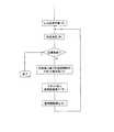
ここで、上述の構成のLED光源を作製した後、LED光源の色度測定を行い、目標色度と異なるものに関しては色度調整工程を加える。図2に工程のフローチャートを示す。図2によれば、上述の構成のLED光源を作製(ア)、色度測定(イ)した後、目標色度
と異なる場合はその測定色度と目標色度の色度差に基づき、滴下する第二の透明樹脂108の量を決定する(ウ)。その後、第二の透明樹脂108をLED光源の反射枠107における凹部に滴下し(エ)、熱硬化させる(オ)ものである。その後確認のため、色度測定を行い(イ)、目標色度と異なる場合は再度色度調整を行っても良い。Here, after the LED light source having the above-described configuration is manufactured, the chromaticity of the LED light source is measured, and a chromaticity adjustment step is added for those different from the target chromaticity. FIG. 2 shows a flowchart of the process. According to FIG. 2, after the LED light source having the above-described configuration is manufactured (a) and chromaticity measurement (b) is performed, if it is different from the target chromaticity, the dropping is performed based on the chromaticity difference between the measured chromaticity and the target chromaticity. The amount of the second
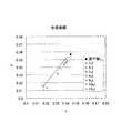
ここで、本発明のベースとなる実験的事実を図3に示す。図3はxy色度図を示すものである。本実験においては滴下する第二の透明樹脂108は封止材106を形成する第一の透明樹脂と同じものとした。本実験は封止材106が硬化され、かつ反射枠107が配置されているLED光源の色度を測定し(滴下無し)、その後、マイクロピペットを用いて、第二の透明樹脂108を反射枠107の凹部に一定量滴下し、熱硬化した後、再度色度測定を行ったものである。図3によれば、LED光源の反射枠107における凹部に滴下する第二の透明樹脂108の量を増やすに従って、滴下無しの場合と比較して色度がx、yともに減る方向、すなわち青色側にシフトすることが分かる。この事実より、第二の透明樹脂108の滴下量と色度のシフト量は相関があり、この相関を用いて目標色度との差に対応する量の第二の透明樹脂108を滴下し硬化することで、目標色度に色度調整したLED光源を作製することができるものである。ここで、本実験における第二の透明樹脂108の滴下量や色度のシフト量の定量値に関してはLED光源の構造等によって様々に変化するものであり、図3中の滴下量や色度のシフト量に限るものではない。 Here, FIG. 3 shows experimental facts on which the present invention is based. FIG. 3 shows an xy chromaticity diagram. In this experiment, the second
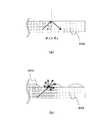
ここで、第二の透明樹脂108を滴下することによってLED光源の色度が変化する機構を図4に示す。図4において、滴下する第二の透明樹脂108と封止材106を形成する第一の透明樹脂は同じ、もしくは屈折率がほぼ等しいものとする。図4(a)は第二の透明樹脂108を滴下する前の状態を示し、図4(b)は第二の透明樹脂108を滴下後硬化した状態を示す。ここで、図4(a)において、LED素子からの青色光が封止材106と空気層との界面に臨界角以上の角度で入射した場合を考える。この場合、青色光は封止材106と空気層との界面で全反射し、再び封止材106内を通過するため、封止材106内の蛍光体に入射し波長変換される場合があり、その場合、LED光源から出射される光線401は黄色光となる。図4(b)においては、図4(a)と同じ角度で封止材106内を通過する青色光を考えると、封止材106を形成する第一の透明樹脂と第二の透明樹脂108は屈折率が同じであるため、封止材106と第二の透明樹脂108の界面において光線は直進し、第二の透明樹脂108と空気層との界面に到達し、全反射する。その内の一部の光は図4(b)に示すように、再び封止材106に入射することなくLED光源から出射されるため、この場合、光線402は青色光となる。上述は一例であるが、このように第二の透明樹脂108により、LED素子からの青色光が蛍光体に入射する確率が減少するため、色度が青色側にシフトするものである。また、滴下する第二の透明樹脂108の量を増やすことで、一度封止材106から出た青色光が再び封止材106内に戻る確率が減少するため、より青色側へのシフト量が増えるものである。 Here, a mechanism in which the chromaticity of the LED light source is changed by dropping the second
上述のように、LED素子と、LED素子からの発光の一部を吸収し波長変換して発光する蛍光体と、第一の透明樹脂内に蛍光体を含む封止材とを、中心に凹部を有する反射枠の凹部領域に配置するLED光源において、封止材を硬化した後に第二の透明樹脂を反射枠の凹部に滴下し硬化することで、第二の透明樹脂の滴下量に応じてLED光源の色度を変化させることができる。従って、封止材を硬化した後の色度と目標色度が異なる場合、その色度差に応じて適量の第二の透明樹脂を滴下後硬化するという非常に簡単な方法で、LED光源の色度を目標色度にすることが可能となる。また、透明樹脂を用いた色度調整のため、発光強度を低下させることなく色度調整が可能である。更に、上述の色度調整方法をLED光源の製造工程に加えることにより、同一製品における色度ばらつきを大幅に低減することが可能となり、LED光源の高付加価値化に繋がるものである。 As described above, the LED element, the phosphor that absorbs a part of the light emitted from the LED element and converts the wavelength and emits light, and the sealing material containing the phosphor in the first transparent resin are recessed in the center. In the LED light source arranged in the concave region of the reflective frame having the following, after the sealing material is cured, the second transparent resin is dropped into the concave portion of the reflective frame and cured, according to the amount of the second transparent resin dripped. The chromaticity of the LED light source can be changed. Therefore, when the chromaticity after the sealing material is cured and the target chromaticity are different, the LED light source can be controlled by a very simple method in which an appropriate amount of the second transparent resin is dropped and cured according to the chromaticity difference. It becomes possible to set the chromaticity to the target chromaticity. In addition, since the chromaticity is adjusted using a transparent resin, it is possible to adjust the chromaticity without reducing the light emission intensity. Furthermore, by adding the above-described chromaticity adjustment method to the LED light source manufacturing process, it is possible to greatly reduce chromaticity variation in the same product, leading to high added value of the LED light source.
また、本実施形態においてはLED光源の研磨等の工程を必要とせず、透明樹脂の滴下
という手法で色度調整を行うため、色度調整工程においてLED光源へダメージを与える危険性がないものである。更に、硬度の低い樹脂で形成される封止材を用いたLED光源においても問題なく色度調整が可能なものである。Further, in the present embodiment, there is no risk of damaging the LED light source in the chromaticity adjustment step because the chromaticity adjustment is performed by the technique of dripping the transparent resin without requiring a step such as polishing the LED light source. is there. Furthermore, even in an LED light source using a sealing material formed of a resin having low hardness, chromaticity adjustment is possible without any problem.
本実施形態においては、封止材106内には蛍光体がほぼ一様に分布しているものとしているがこれに限るものではなく、封止材106内において蛍光体の濃度分布がある場合でも同様の方法で色度調整することが可能である。 In the present embodiment, the phosphors are assumed to be distributed almost uniformly in the
(第二の実施形態)
次に第二の実施形態について説明する。図5は本実施形態の色度調整工程のフローチャートを示す。本実施形態におけるLED光源の断面図等は図1に示す第一の実施形態と同様である。第一の実施形態と同様、LED光源において、LED素子101は基板102上に配置され、LED素子101と基板102の配線導体104はボンディングワイヤ105を用いて電気的に接続される。また、LED素子101の周囲にはLED素子101やボンディングワイヤ105を保護するための封止材106を配置する。封止材106内には第一の透明樹脂と混ざり合った状態で蛍光体を配置し、LED素子101からの青色光と蛍光体からの黄色光が混ざり合って擬似白色光を出射するものである。また、封止樹脂106の外側には反射枠107を配置する。(Second embodiment)
Next, a second embodiment will be described. FIG. 5 shows a flowchart of the chromaticity adjustment process of this embodiment. The sectional view of the LED light source in this embodiment is the same as that of the first embodiment shown in FIG. As in the first embodiment, in the LED light source, the
ここで、本実施形態においては上述の構成のLED光源を作製する際、目標色度と異なる色度を狙って作製する。具体的には目標色度に対してxy色度図におけるx、yがともに大きい値となるよう、すなわち、より黄色側を狙って作製する(カ)。方法としては封止材106内の蛍光体の量を増やす方法などが考えられる。作製したLED光源は色度測定を行い、測定した色度と目標色度との色度差を計測する(キ)。次に、その測定色度と目標色度の色度差に基づき、滴下する第二の透明樹脂108の量を決定する(ク)。その後、第二の透明樹脂108をLED光源の反射枠107における凹部に滴下し(ケ)、熱硬化させる(コ)ものである。その後確認のため、色度測定を行い(サ)、目標色度と異なる場合は再度色度調整を行っても良い。 Here, in the present embodiment, when the LED light source having the above-described configuration is manufactured, the LED light source is manufactured aiming at a chromaticity different from the target chromaticity. Specifically, it is produced so that both x and y in the xy chromaticity diagram are larger than the target chromaticity, that is, the yellow side is aimed (F). As a method, a method of increasing the amount of the phosphor in the sealing
封止材106を硬化させたLED光源における反射枠の凹部に第二の透明樹脂108を滴下後硬化することによってLED光源の色度が変化する機構については、第一の実施形態と同様であり、第二の透明樹脂108により、LED素子101からの青色光が蛍光体に入射する確率が減少することで色度が青色側にシフトするものである。 The mechanism for changing the chromaticity of the LED light source by dripping and curing the second
上述のように、本実施形態においては封止材を硬化した後に第二の透明樹脂を反射枠の凹部に滴下し硬化することで、第二の透明樹脂の滴下量に応じてLED光源の色度を変化させることができるものである。また、予めLED光源を目標色度に対して黄色側に作製しておき、色度調整工程により目標色度とすることにより、すべてのLED光源に対して同様の製造工程を行うことになり、工程の簡易化が得られる。また、擬似白色光における黄色よりの光や青色よりの光などより広い範囲の光線を出射するLED光源を作製することが可能である。 As described above, in the present embodiment, after the sealing material is cured, the second transparent resin is dropped into the concave portion of the reflection frame and cured, so that the color of the LED light source according to the dropping amount of the second transparent resin. The degree can be changed. Also, by preparing the LED light source on the yellow side with respect to the target chromaticity in advance and setting the target chromaticity by the chromaticity adjustment step, the same manufacturing process will be performed for all the LED light sources, Simplification of the process is obtained. Moreover, it is possible to produce an LED light source that emits a wider range of light rays such as light from yellow or light from blue in pseudo white light.
(第三の実施形態)
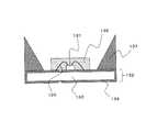
次に第三の実施形態について説明する。図6は本発明の第三の実施形態を示す図であり、本発明の第三の実施形態におけるLED光源の断面図である。図6におけるLED光源において、第一の実施形態と同様に、LED素子101は基板102上にダイボンドペーストなどを用いて実装される。基板102はガラスエポキシ、セラミックスなどの基材103上にLED素子101に電力を供給するための配線導体104がパターン形成されたものである。また、配線導体104には金属など導電性と高反射率を備えたものが用いられる。(Third embodiment)
Next, a third embodiment will be described. FIG. 6 is a diagram showing a third embodiment of the present invention, and is a cross-sectional view of an LED light source in the third embodiment of the present invention. In the LED light source in FIG. 6, the
また、LED素子101と配線導体104はLED素子101上のボンディング用パッドと配線導体104を接続するボンディングワイヤ105を用いて電気的に接続される。LED素子101は配線導体104、ボンディングワイヤ105を介して外部より電力を供給され、発光するものである。ここで、本実施形態においては、LED素子101はInGaNなどの窒化物系化合物半導体であり、青色光を発光するものとする。 The
また、LED素子101の周囲にはLED素子101やボンディングワイヤ105を覆うように封止材602を配置する。封止材602を配置する目的の一つはLED素子101やボンディングワイヤ105の保護であり、所望の形をした型などに流し込んだ後、熱硬化させることにより、硬化するものである。封止材602の熱硬化後の硬度は様々であり、ボンディングワイヤ105の切断を防ぎLED光源の信頼性を上げるためには、硬度が低く比較的柔らかいタイプのものが用いられることが多い。また、封止材602を配置する二つ目の目的として、封止材602内には第一の透明樹脂と混ざり合った状態で蛍光体を配置する。本実施形態においては、封止材602内に蛍光体がほぼ一様に分布しているものとする。蛍光体はLED素子101からの青色発光の一部を吸収し波長変換して黄色を発光するもので、LED光源としてはLED素子101からの青色光と蛍光体からの黄色光が混ざり合って擬似白色光を出射するものである。LED光源としては更に、封止材602の外側に反射枠107を配置することが多いが、本実施形態においては反射枠107の有無に関係なく効果を得られるものである。 Further, a sealing
ここで、上述の構成のLED光源を作製した後、LED光源の色度測定を行い、色度調整工程を加える。工程としては上述の実施形態と同様で、図2もしくは図5に示すフローチャートに従って色度調整を行う。図2においては第一の実施形態と同様、LED光源を作製(ア)、色度測定(イ)した後、目標色度と異なる場合はその測定色度と目標色度の色度差に基づき、滴下する第二の透明樹脂601の量を決定する(ウ)。その後、第二の透明樹脂601を封止材602の上面に滴下し(エ)、熱硬化させる(オ)ものである。その後確認のため色度測定を行い(イ)、目標色度と異なる場合は再度色度調整を行っても良い。 Here, after producing the LED light source of the above-mentioned structure, the chromaticity measurement of an LED light source is performed, and a chromaticity adjustment process is added. The process is the same as in the above-described embodiment, and chromaticity adjustment is performed according to the flowchart shown in FIG. In FIG. 2, as in the first embodiment, after producing the LED light source (a) and measuring the chromaticity (b), if different from the target chromaticity, based on the chromaticity difference between the measured chromaticity and the target chromaticity. The amount of the second
また、図5においては第二の実施形態と同様、LED光源を作製する際、目標色度と異なる色度を狙って作製する。具体的には目標色度に対して色度がx、yともに大きい値となるよう、すなわち、より黄色側を狙って作製する(カ)。方法としては封止材602内の蛍光体の量を増やす方法などが考えられる。作製したLED光源は色度測定を行い、測定した色度と目標色度との色度差を計測する(キ)。次に、その測定色度と目標色度の色度差に基づき、滴下する第二の透明樹脂601の量を決定する(ク)。その後、第二の透明樹脂601を封止材602の上面に滴下し(ケ)、熱硬化させる(コ)ものである。その後確認のため、再度色度測定を行っても良い(サ)。ここで、第二の透明樹脂601は適量を滴下した場合、表面張力により封止材602上に凸レンズの凸部のような形状になって留まるものであり、滴下量に応じて曲率が変化するものである。 Further, in FIG. 5, similarly to the second embodiment, when the LED light source is manufactured, it is manufactured aiming at a chromaticity different from the target chromaticity. Specifically, the chromaticity is produced so that both the x and y values are larger than the target chromaticity, that is, the yellow side is aimed (F). As a method, a method of increasing the amount of the phosphor in the sealing
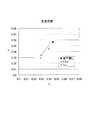
ここで、本発明のベースとなる実験的事実を図7に示す。本実験においては滴下する第二の透明樹脂601は封止材602を形成する第一の透明樹脂と同じものとした。本実験は封止材602が硬化されているLED光源の色度を測定し(滴下無し)、その後、マイクロピペットを用いて、第二の透明樹脂601を封止材602の上面に一定量滴下し、熱硬化した後、再度色度測定を行ったものである。図7によれば、LED光源の封止材上面に滴下する第二の透明樹脂601の量を増やすに従って、滴下無しの場合と比較して色度がx、yともに減る方向、すなわち青色側にシフトする現象が見られる。この事実より、第二の透明樹脂601の滴下量と色度のシフト量は相関があり、この相関を用いて目標色度との差に対応する量の第二の透明樹脂601を滴下し硬化することで、目標色度に色度
調整したLED光源を作製することができるものである。ここで本実験における、第二の透明樹脂601の滴下量や色度のシフト量の定量値に関してはLED光源の構造等によって様々に変化するものであり、図7中の滴下量や色度のシフト量に限るものではない。Here, FIG. 7 shows experimental facts that form the basis of the present invention. In this experiment, the dropped second
ここで、封止材602上に第二の透明樹脂601を滴下することによってLED光源の色度が変化する機構を図8に示す。図8において、滴下する第二の透明樹脂601と封止材602を形成する第一の透明樹脂は同じ、もしくは屈折率がほぼ等しいものとする。図8(a)は第二の透明樹脂601を滴下する前の状態を示し、図8(b)は第二の透明樹脂601を滴下後硬化した状態を示す。図8(a)において、LED素子からの青色光が封止材602と空気層との界面に、界面の法線方向に対してある角度θ1で入射した場合を考える。ここで、青色光は封止材602の中心から、すなわちLED素子方向から入射するものとする。このとき、θ1が封止材602と空気層との界面における臨界角θcより大きい場合(θ1>θc)は、光線は全反射し、全反射した光線は再び封止材602内を通過するため、封止材602内に一様に分布している蛍光体に入射し波長変換される可能性が増える。図8(b)においては、図8(a)と同様の角度で封止材602内を通過する光線を考えると、封止材602を形成する第一の透明樹脂と第二の透明樹脂601は屈折率が同じであるため、封止材602と第二の透明樹脂601の界面において光線はそのまま直進し、透明樹脂601と空気層との界面に到達する。このとき、第二の透明樹脂601と空気層の界面は上述のように曲率を持っているため、界面の法線方向と光線のなす角θ2はθ1よりも小さくなる(θ2<θ1)。このとき、θ2<θcの場合、光線は界面で全反射せず、青色光が出射される。ここで、θ1>θcかつθ2<θcという光線に関しては、第二の透明樹脂601がない場合はその一部が黄色光であるが、第二の透明樹脂601がある場合は青色光となるため、第二の透明樹脂601によってLED光源の色度が青色方向にシフトするものである。ここで、界面に到達する青色光としては封止材602の外側から中心方向に向かう光線も存在し、その場合、上述の機構とは逆に第二の透明樹脂601により出射される青色光が減少することが考えられるが、封止材602の中心から外側に向かう青色光と比較して強度が小さいため、全体としては青色方向にシフトするものである。 Here, a mechanism in which the chromaticity of the LED light source is changed by dropping the second
第二の透明樹脂601を滴下することにより色度が変化する機構において、上述の例は一例であるが、このように第二の透明樹脂601により、LED素子からの青色光が蛍光体に入射する確率が減少するため、LED光源の色度が青色側にシフトするものである。また、滴下する第二の透明樹脂601の量を増やすことで、第二の透明樹脂601と空気層との界面の曲率が大きくなり、上述のθ1>θcかつθ2<θcという光線の割合が増えるため、よりシフト量が増えるものである。 In the mechanism in which the chromaticity is changed by dropping the second
上述のように、LED素子と、LED素子からの発光の一部を吸収し波長変換して発光する蛍光体と、第一の透明樹脂内に蛍光体をほぼ均一の分布で含む封止材とを有するLED光源において、封止材を硬化した後に封止材の上面に第二の透明樹脂を滴下し硬化することで、第二の透明樹脂の滴下量に応じてLED光源の色度を変化させることができる。従って、封止材を硬化した後の色度と目標色度が異なる場合、その色度差に応じて適量の透明樹脂を滴下後硬化するという非常に簡単な方法で、LED光源の色度を微調整し目標色度にすることが可能となる。また、透明樹脂を用いるため、発光強度を低下させることなく色度調整が可能である。また、上述の色度調整方法をLED光源の製造工程に加えることにより、同一製品における色度ばらつきを大幅に低減することが可能となる。 As described above, the LED element, the phosphor that absorbs part of the light emitted from the LED element and converts the wavelength to emit light, and the sealing material that includes the phosphor in the first transparent resin in a substantially uniform distribution In the LED light source having, after curing the encapsulant, the second transparent resin is dropped on the upper surface of the encapsulant and cured to change the chromaticity of the LED light source according to the amount of the second transparent resin dripped Can be made. Therefore, if the chromaticity after curing the sealing material is different from the target chromaticity, the chromaticity of the LED light source can be adjusted by a very simple method of curing after dropping a suitable amount of transparent resin according to the chromaticity difference. Fine adjustment can be made to achieve the target chromaticity. In addition, since a transparent resin is used, chromaticity can be adjusted without reducing the emission intensity. Further, by adding the above-described chromaticity adjustment method to the manufacturing process of the LED light source, it is possible to greatly reduce chromaticity variation in the same product.
また、本実施形態においても、上述の実施形態と同様、LED光源の研磨等の工程を必要とせず、透明樹脂の滴下という手法で色度調整を行うため、色度調整工程においてLED光源へダメージを与えることがない。更に、硬度の低い樹脂で形成される封止材を用いたLED光源においても問題なく色度調整が可能なものである。 Also in this embodiment, similarly to the above-described embodiment, a process such as polishing of the LED light source is not required, and the chromaticity adjustment is performed by a technique of dropping a transparent resin, so that the LED light source is damaged in the chromaticity adjustment process. Never give. Furthermore, even in an LED light source using a sealing material formed of a resin having low hardness, chromaticity adjustment is possible without any problem.
(第四の実施形態)
次に第四の実施形態について説明する。図9は本発明の第四の実施形態を示す図であり、本発明の第四の実施形態におけるLED光源の断面図である。上述の実施形態と同様、LED光源において、LED素子101は基板102上に配置され、LED素子101と基板102の配線導体104はボンディングワイヤ105を用いて電気的に接続される。また、LED素子101の周囲にはLED素子101やボンディングワイヤ105を覆うように封止材602を配置する。封止材602はLED素子101やボンディングワイヤ105を保護するとともに、その中には第一の透明樹脂と混ざり合った状態で蛍光体を配置し、LED素子101からの青色光と蛍光体からの黄色光が混ざり合って擬似白色光を出射するものである。(Fourth embodiment)
Next, a fourth embodiment will be described. FIG. 9 is a diagram showing a fourth embodiment of the present invention, and is a cross-sectional view of an LED light source in the fourth embodiment of the present invention. As in the above-described embodiment, in the LED light source, the
ここで、上述の構成のLED光源を作製した後、LED光源の色度測定を行い、色度調整工程を加える。工程としては、図10もしくは図11に示すフローチャートに従って色度調整を行う。図10においては、LED光源を作製(タ)、色度測定(チ)した後、目標色度と異なる場合はその測定色度と目標色度の色度差に基づき、滴下する第二の透明樹脂603のスポットの数を決定する(ツ)。その後、第二の透明樹脂603を封止材602の上面にスポット状に滴下し(テ)、熱硬化させる(ト)ものである。その後確認のため、再度色度測定(チ)を行っても良い。 Here, after producing the LED light source of the above-mentioned structure, the chromaticity measurement of an LED light source is performed, and a chromaticity adjustment process is added. As a process, chromaticity adjustment is performed according to the flowchart shown in FIG. In FIG. 10, after the LED light source is manufactured (t) and measured for chromaticity (h), if it differs from the target chromaticity, the second transparent to be dropped based on the chromaticity difference between the measured chromaticity and the target chromaticity The number of spots of the
また、図11においては、LED光源を作製する際、目標色度と異なる色度を狙って作製する。具体的には目標色度に対して色度がx、yともに大きい値となるよう、すなわち、より黄色側を狙って作製する(ナ)。方法としては封止材602内の蛍光体の量を増やす方法などが考えられる。作製したLED光源は色度測定を行い、測定した色度と目標色度との色度差を計測する(ニ)。次に、その測定色度と目標色度の色度差に基づき、滴下する第二の透明樹脂603のスポットの数を決定する(ヌ)。その後、第二の透明樹脂603を封止材602の上面に滴下し(ネ)、熱硬化させる(ノ)ものである。その後確認のため、再度色度測定を行っても良い(ハ)。ここで、スポットとは微小領域を示し、微小量の第二の透明樹脂603を滴下することにより、第二の透明樹脂603が封止材602の上面にスポット状に配置されるものである。また、第二の透明樹脂603のスポットの容量はほぼ一定であるものとする。 Moreover, in FIG. 11, when producing an LED light source, it produces aiming at chromaticity different from target chromaticity. Specifically, the chromaticity is produced so that both the x and y values are larger than the target chromaticity, that is, the yellow side is aimed (N). As a method, a method of increasing the amount of the phosphor in the sealing
このとき、封止材602上に第二の透明樹脂603をスポット状に滴下することによってLED光源の色度が青色側に変化するものである。色度が変化する機構としては、第一に、第二の透明樹脂603のスポットが形成された箇所においては、樹脂と空気層の界面が曲率を持ったものとなるため、第三の実施形態と同様の機構で、LED光源から出射される青色光の割合が増えるものである。また、第二に、スポット径が小さい場合は樹脂と空気層の界面に到達した青色光がスポットにより散乱することが挙げられる。図12において、図12(a)は第二の透明樹脂603を滴下する前の状態を示し、図12(b)は第二の透明樹脂603を滴下した後硬化した状態を示す。図12(a)において、LED素子からの青色光が封止材602と空気層との界面に、界面の法線方向に対してある角度θ3で入射した場合を考える。このとき、θ3が封止材602と空気層との界面における臨界角θcより大きい場合(θ3>θc)は、光線は全反射し、全反射した光線は再び封止材602内を通過するため、封止材602内に一様に分布している蛍光体に入射し波長変換される可能性が増えるものである。図12(b)においては、図12(a)と同様の角度で封止材602内を通過する青色光を考えると、第二の透明樹脂603のスポットにより散乱を起こし、一部はそのまま空気層に出射されるため、図12(a)と比較して封止材602内の蛍光体に入射する割合が減少するものである。従って、第二の透明樹脂603のスポットによってLED光源の色度が青色方向にシフトするものである。 At this time, the chromaticity of the LED light source is changed to the blue side by dropping the second
第二の透明樹脂603を滴下することにより色度が変化する機構において、上述の例は一例であるが、このように第二の透明樹脂603により、LED素子からの青色光が蛍光体に入射する確率が減少するため、LED光源の色度が青色側にシフトするものである。また、滴下する第二の透明樹脂603のスポットの数を増やすことで、よりシフト量が増えるものである。 In the mechanism in which the chromaticity is changed by dropping the second
上述のように、LED素子と、LED素子からの発光の一部を吸収し波長変換して発光する蛍光体と、第一の透明樹脂内に蛍光体をほぼ均一の分布で含む封止材とを有するLED光源において、封止材を硬化した後に封止材の上面に第二の透明樹脂をスポット上に滴下し硬化することで、第二の透明樹脂のスポットの数に応じてLED光源の色度を変化させることができる。従って、封止材を硬化した後の色度と目標色度が異なる場合、その色度差に応じて適量数の第二の透明樹脂のスポットを滴下後硬化するという非常に簡単な方法で、LED光源の色度を微調整し目標色度にすることが可能となる。また、透明樹脂を用いるため、発光強度を低下させることなく色度調整が可能である。また、上述の色度調整方法をLED光源の製造工程に加えることにより、同一製品における色度ばらつきを大幅に低減することが可能となる。更に、本方式によれば、一回の滴下における第二の透明樹脂の量は固定にすることができるため、例えば第二の透明樹脂を滴下する装置の設定等を調整することなく、滴下の回数のみを変えることで調整する色度幅を変化させることが可能であり、色度調整工程の簡易化につながるものである。 As described above, the LED element, the phosphor that absorbs part of the light emitted from the LED element and converts the wavelength to emit light, and the sealing material that includes the phosphor in the first transparent resin in a substantially uniform distribution In the LED light source having the following, after the sealing material is cured, the second transparent resin is dropped onto the upper surface of the sealing material on the spot and cured, so that the LED light source can be selected according to the number of spots of the second transparent resin. The chromaticity can be changed. Therefore, when the chromaticity after curing the sealing material and the target chromaticity are different, in a very simple method of curing after dropping a suitable number of spots of the second transparent resin according to the chromaticity difference, The chromaticity of the LED light source can be finely adjusted to the target chromaticity. In addition, since a transparent resin is used, chromaticity can be adjusted without reducing the emission intensity. Further, by adding the above-described chromaticity adjustment method to the manufacturing process of the LED light source, it is possible to greatly reduce chromaticity variation in the same product. Furthermore, according to this method, since the amount of the second transparent resin in one dropping can be fixed, for example, without adjusting the setting of the apparatus for dropping the second transparent resin, etc. It is possible to change the chromaticity width to be adjusted by changing only the number of times, leading to simplification of the chromaticity adjustment process.
ここで、本実施形態においては、封止材602上に第二の透明樹脂603を滴下する手法を用いているが、例えば、インクジェット方式などを用いて第二の透明樹脂603を封止材602上に向けて吐出する方法によっても同様の効果が得られるものである。 Here, in this embodiment, a method of dropping the second
上述の各実施形態においては、封止材を硬化後に滴下する第二の透明樹脂は封止材を形成する第一の透明樹脂と同じもの、もしくは屈折率がほぼ等しいものとしている。この場合、封止材と第二の透明樹脂の界面において光線がほとんど反射することがないため、第二の透明樹脂の滴下量に対する色度の変化量が大きいと考えられる。しかし、これに限るものではなく、第一の透明樹脂と第二の透明樹脂の屈折率が異なる場合においても、第二の透明樹脂の滴下量に対する色度の変化量は若干低下するが、同様の機構で色度が変化するものである。 In each of the above-described embodiments, the second transparent resin dropped after the sealing material is cured is the same as the first transparent resin forming the sealing material, or the refractive index is substantially equal. In this case, since the light beam hardly reflects at the interface between the sealing material and the second transparent resin, it is considered that the amount of change in chromaticity with respect to the amount of the second transparent resin dropped is large. However, the present invention is not limited to this, and even when the refractive indexes of the first transparent resin and the second transparent resin are different, the amount of change in chromaticity with respect to the amount of the second transparent resin dropped slightly decreases. The chromaticity is changed by this mechanism.
また、上述の各実施形態においては、透明樹脂を封止材上に配置することによって色度調整を行っているが、透明樹脂に限るものではなく、例えばSiO2、ITO、ZnO、Al2O3、TiO2、MgF2などの透明無機材料を用い、透明無機材料を封止材上に配置することによっても色度調整を行うことが可能である。Further, in each of the above-described embodiments, the chromaticity adjustment is performed by arranging the transparent resin on the sealing material, but the chromaticity is not limited to the transparent resin. For example, SiO2 , ITO, ZnO, Al2 O3 It is also possible to adjust the chromaticity by using a transparent inorganic material such as TiO2 or MgF2 and disposing the transparent inorganic material on the encapsulant.
上述の実施形態において、LED素子とは半導体発光素子のことを示し、LED光源とはLED素子等が実装され、パッケージ化された電子部品のことを示すものとする。 In the above-described embodiment, the LED element indicates a semiconductor light emitting element, and the LED light source indicates an electronic component on which the LED element or the like is mounted and packaged.
101 LED素子
102 基板
103 基材
104 配線導体
105 ボンディングワイヤ
106 封止材
107 反射枠
108、601、603 第二の透明樹脂
602 封止材101
Claims (19)
Translated fromJapanesePriority Applications (1)
| Application Number | Priority Date | Filing Date | Title |
|---|---|---|---|
| JP2008030165AJP2009193994A (en) | 2008-02-12 | 2008-02-12 | Led light source and chromaticity adjustment method thereof |
Applications Claiming Priority (1)
| Application Number | Priority Date | Filing Date | Title |
|---|---|---|---|
| JP2008030165AJP2009193994A (en) | 2008-02-12 | 2008-02-12 | Led light source and chromaticity adjustment method thereof |
Publications (1)
| Publication Number | Publication Date |
|---|---|
| JP2009193994Atrue JP2009193994A (en) | 2009-08-27 |
Family
ID=41075795
Family Applications (1)
| Application Number | Title | Priority Date | Filing Date |
|---|---|---|---|
| JP2008030165APendingJP2009193994A (en) | 2008-02-12 | 2008-02-12 | Led light source and chromaticity adjustment method thereof |
Country Status (1)
| Country | Link |
|---|---|
| JP (1) | JP2009193994A (en) |
Cited By (11)
| Publication number | Priority date | Publication date | Assignee | Title |
|---|---|---|---|---|
| JP2009260244A (en)* | 2008-03-25 | 2009-11-05 | Toshiba Corp | Light-emitting device and method of manufacturing the same, and apparatus for manufacturing light-emitting device |
| JP2009283887A (en)* | 2008-04-24 | 2009-12-03 | Citizen Holdings Co Ltd | Led light source and chromaticity adjustment method for the led light source |
| JP2011091101A (en)* | 2009-10-20 | 2011-05-06 | Stanley Electric Co Ltd | Light emitting device and method of manufacturing light emitting device |
| CN102537692A (en)* | 2010-12-22 | 2012-07-04 | 海洋王照明科技股份有限公司 | Lamp |
| US8268644B2 (en) | 2008-03-25 | 2012-09-18 | Kabushiki Kaisha Toshiba | Light emitting device, and method and apparatus for manufacturing same |
| JP2013512586A (en)* | 2009-12-01 | 2013-04-11 | ブリッジラックス インコーポレイテッド | Method and system for dynamically mixing and injecting phosphors in situ |
| JP2013118244A (en)* | 2011-12-02 | 2013-06-13 | Citizen Holdings Co Ltd | Semiconductor light-emitting device and lighting apparatus using the same |
| JP5261742B1 (en)* | 2012-08-13 | 2013-08-14 | 株式会社昭和真空 | Method for manufacturing light emitting device and method for adjusting chromaticity of light emitting device |
| JP2014057048A (en)* | 2012-08-13 | 2014-03-27 | Showa Shinku Co Ltd | Atomic layer deposition device, method of manufacturing light-emitting device, and chromaticity adjustment method of light-emitting device |
| CN104241505A (en)* | 2013-06-19 | 2014-12-24 | 深圳市瑞丰光电子股份有限公司 | Surface excitation LED lamp |
| US8952409B2 (en) | 2012-09-07 | 2015-02-10 | Kabushiki Kaisha Toshiba | Light emitting device including a fluorescent material layer |
- 2008
- 2008-02-12JPJP2008030165Apatent/JP2009193994A/enactivePending
Cited By (14)
| Publication number | Priority date | Publication date | Assignee | Title |
|---|---|---|---|---|
| JP2009260244A (en)* | 2008-03-25 | 2009-11-05 | Toshiba Corp | Light-emitting device and method of manufacturing the same, and apparatus for manufacturing light-emitting device |
| US8268644B2 (en) | 2008-03-25 | 2012-09-18 | Kabushiki Kaisha Toshiba | Light emitting device, and method and apparatus for manufacturing same |
| JP2009283887A (en)* | 2008-04-24 | 2009-12-03 | Citizen Holdings Co Ltd | Led light source and chromaticity adjustment method for the led light source |
| JP2011091101A (en)* | 2009-10-20 | 2011-05-06 | Stanley Electric Co Ltd | Light emitting device and method of manufacturing light emitting device |
| JP2013512586A (en)* | 2009-12-01 | 2013-04-11 | ブリッジラックス インコーポレイテッド | Method and system for dynamically mixing and injecting phosphors in situ |
| CN102537692A (en)* | 2010-12-22 | 2012-07-04 | 海洋王照明科技股份有限公司 | Lamp |
| JP2013118244A (en)* | 2011-12-02 | 2013-06-13 | Citizen Holdings Co Ltd | Semiconductor light-emitting device and lighting apparatus using the same |
| JP5261742B1 (en)* | 2012-08-13 | 2013-08-14 | 株式会社昭和真空 | Method for manufacturing light emitting device and method for adjusting chromaticity of light emitting device |
| KR20140021977A (en)* | 2012-08-13 | 2014-02-21 | 가부시키가이샤 쇼와 신쿠 | Method for manufacturing light emitting device, method for adjusting chromaticity of light emitting device and apparatus for adjusting chromaticity of light emitting device |
| JP2014057048A (en)* | 2012-08-13 | 2014-03-27 | Showa Shinku Co Ltd | Atomic layer deposition device, method of manufacturing light-emitting device, and chromaticity adjustment method of light-emitting device |
| KR102039430B1 (en) | 2012-08-13 | 2019-11-01 | 가부시키가이샤 쇼와 신쿠 | Method for manufacturing light emitting device, method for adjusting chromaticity of light emitting device and apparatus for adjusting chromaticity of light emitting device |
| US8952409B2 (en) | 2012-09-07 | 2015-02-10 | Kabushiki Kaisha Toshiba | Light emitting device including a fluorescent material layer |
| US9240531B2 (en) | 2012-09-07 | 2016-01-19 | Kabushiki Kaisha Toshiba | Light emitting device including reinforcing member |
| CN104241505A (en)* | 2013-06-19 | 2014-12-24 | 深圳市瑞丰光电子股份有限公司 | Surface excitation LED lamp |
Similar Documents
| Publication | Publication Date | Title |
|---|---|---|
| JP2009193994A (en) | Led light source and chromaticity adjustment method thereof | |
| CN109860381B (en) | Light emitting device and method of manufacturing the same | |
| US7084435B2 (en) | Light emitting device using LED | |
| US8592849B2 (en) | LED light source and chromaticity adjustment method for LED light source | |
| KR101906863B1 (en) | A light emitting module, a lamp, a luminaire and a display device | |
| EP2573812B1 (en) | Light-emitting apparatus | |
| KR101639353B1 (en) | Semiconductor light-emitting device and method for manufacturing thereof | |
| CN103797597B (en) | Light emitting module, lamp, luminaire and display device | |
| JP2009193995A (en) | Led light source and chromaticity adjustment method thereof | |
| WO2014174618A1 (en) | Light source device and vehicle light fixture | |
| JP4796031B2 (en) | Vehicle headlight light source and vehicle headlight | |
| US20100301353A1 (en) | Led lighting device having a conversion reflector | |
| JP2010016029A (en) | Led light source | |
| JP7174216B2 (en) | Light-emitting modules and integrated light-emitting modules | |
| CN118198047A (en) | Light emitting device | |
| US20090134415A1 (en) | Light emitting element and method for producing the same | |
| JP6925100B2 (en) | Light emitting device | |
| JP2012069577A (en) | Semiconductor light-emitting device and method of manufacturing the same | |
| JP2010225791A (en) | Semiconductor light emitting device | |
| WO2011016295A1 (en) | Light emitting device and method for manufacturing light emitting device | |
| KR20160036489A (en) | Light emitting device | |
| JP2009070892A (en) | Led light source | |
| JP6997869B2 (en) | Wavelength conversion element and light source device | |
| JP2013149690A (en) | Light-emitting device and illuminating device | |
| JP7212296B2 (en) | light emitting device |