JP2009193240A - Mobile robot and environmental map generation method - Google Patents
Mobile robot and environmental map generation methodDownload PDFInfo
- Publication number
- JP2009193240A JP2009193240AJP2008032010AJP2008032010AJP2009193240AJP 2009193240 AJP2009193240 AJP 2009193240AJP 2008032010 AJP2008032010 AJP 2008032010AJP 2008032010 AJP2008032010 AJP 2008032010AJP 2009193240 AJP2009193240 AJP 2009193240A
- Authority
- JP
- Japan
- Prior art keywords
- position data
- dimensional position
- new
- mobile robot
- map
- Prior art date
- Legal status (The legal status is an assumption and is not a legal conclusion. Google has not performed a legal analysis and makes no representation as to the accuracy of the status listed.)
- Pending
Links
Images


Landscapes
- Instructional Devices (AREA)
- Image Processing (AREA)
- Control Of Position, Course, Altitude, Or Attitude Of Moving Bodies (AREA)
- Image Analysis (AREA)
Abstract
Translated fromJapaneseDescription
Translated fromJapanese本発明は、移動ロボットに関し、特に移動ロボットの移動のために参照される環境地図の生成方法に関する。 The present invention relates to a mobile robot, and more particularly to a method for generating an environmental map referred to for movement of the mobile robot.
移動ロボットは、環境地図を参照することによって移動経路を計画し、当該移動経路に従って移動を行う。例えば、環境地図は、移動ロボットが移動を行う2次元の移動空間を格子状に分割するとともに、格子に囲まれた各々のセルが、移動ロボットにとって移動可能な領域であるか否かを表したグリッド地図として作成される。 The mobile robot plans a movement route by referring to the environment map, and moves according to the movement route. For example, the environment map divides a two-dimensional movement space in which the mobile robot moves into a grid, and indicates whether each cell surrounded by the grid is a movable area for the mobile robot. Created as a grid map.
環境地図の作成は、例えば、レーザレンジファインダなどの視覚センサを搭載した移動ロボット自身によって行なわれる。具体的には、移動ロボットに搭載された視覚センサを用いて、移動ロボット自身が移動空間内を移動しながら外部環境の3次元位置データを生成する。そして、移動ロボットは、複数の異なるロボット位置で計測された3次元位置データを、オドメトリより推定される移動ロボットの位置及び姿勢に基づいて繋ぎ合わせることによって、複数の局所的な3次元位置データが統合された広範囲の環境地図を生成する。このように移動ロボットの自己位置推定と環境地図の構築を同時に行なう技術は、SLAM(Simultaneous Localization and Mapping)と呼ばれる(例えば、特許文献1〜2を参照)。 The environmental map is created, for example, by the mobile robot itself equipped with a visual sensor such as a laser range finder. Specifically, using a visual sensor mounted on the mobile robot, the mobile robot itself generates three-dimensional position data of the external environment while moving in the movement space. Then, the mobile robot connects the three-dimensional position data measured at a plurality of different robot positions based on the position and posture of the mobile robot estimated from odometry, so that a plurality of local three-dimensional position data is obtained. Generate a comprehensive integrated environmental map. The technique for simultaneously estimating the mobile robot's self-location and constructing the environment map is called SLAM (Simultaneous Localization and Mapping) (see, for example,
例えば、オドメトリより推定されたロボットの位置及び姿勢に基づいて、複数地点で計測された3次元位置データを移動空間に固定されたグローバル座標系へ座標変換し、これらをグローバル座標上で統合することによって、グローバル座標系での環境地図が生成される。また、各々のロボット位置で得られた3次元位置データに対して平面検出処理や障害物検出処理を行って狭小領域に関する複数の地図(以下、ローカル地図と呼ぶ)を作成した後に、複数のローカル地図をオドメトリに基づいて統合して広範な環境地図を作成する場合もある。 For example, based on the position and orientation of the robot estimated from odometry, coordinate conversion of 3D position data measured at multiple points into a global coordinate system fixed in the movement space, and integrating these on global coordinates Generates an environmental map in the global coordinate system. In addition, after performing plane detection processing and obstacle detection processing on the three-dimensional position data obtained at each robot position to create a plurality of maps relating to narrow areas (hereinafter referred to as local maps), a plurality of local In some cases, maps may be integrated based on odometry to create a broad environmental map.
特許文献1には、脚歩行型の移動ロボットの足平が接している床面を含む複数の平面を3次元位置データから検出し、これら複数の平面の検出結果を用いて障害物領域と移動可能領域とが特定された環境地図を生成する技術が開示されている。 In
また、特許文献2に開示された移動ロボット用の環境地図の生成方法は、概略以下の手順(1)〜(5)を含む。
(1)レーザレンジファインダによって得た第Nフレームの3次元位置データをオドメトリより推定されるロボット位置及び姿勢に基づいてグローバル座標系に変換する。
(2)グローバル座標系に変換した後の第Nフレームの3次元位置データから複数の線分を認識する。
(3)認識した複数の線分を、異なるロボット位置で過去に計測された第N−1フレームの3次元位置データから認識された複数の線分と対応付ける。
(4)対応付けられた線分間の位置及び向きの差の平均値を、オドメトリから推定されたロボット位置及び姿勢の推定値の誤差とする。
(5)ロボット位置及び姿勢の推定値の誤差を打ち消すように第Nフレームの3次元位置データを座標変換した後に、第Nフレームと第N−1フレームの3次元位置データを繋ぎ合わせて統合し、改めて線分抽出を行う。
(1) The three-dimensional position data of the Nth frame obtained by the laser range finder is converted into a global coordinate system based on the robot position and posture estimated from odometry.
(2) Recognize a plurality of line segments from the three-dimensional position data of the Nth frame after conversion to the global coordinate system.
(3) The plurality of recognized line segments are associated with the plurality of line segments recognized from the three-dimensional position data of the (N-1) th frame measured in the past at different robot positions.
(4) The average value of the difference between the position and orientation of the associated line segment is taken as the error of the estimated value of the robot position and posture estimated from odometry.
(5) After coordinate-transforming the 3D position data of the Nth frame so as to cancel the error of the estimated values of the robot position and orientation, the 3D position data of the Nth frame and the (N-1) th frame are joined and integrated. Then, line segment extraction is performed again.
上述した文献1及び2は、オドメトリを用いて推定される移動ロボットの位置及び姿勢に基づいて3次元位置データを座標変換し、異なるロボット位置で計測された3次元位置データを互いに繋ぎ合わせて広範囲の環境地図を生成する技術を開示している。
しかしながら、オドメトリとして取得される移動ロボット内界の計測データ(車輪回転量、関節角など)は、移動ロボットの移動量が大きくなるにつれて誤差が蓄積されていく。さらに、オドメトリに反映されない移動ロボットの揺れや振動のために3次元位置データの信頼性が損なわれる場合がある。このため、異なるロボット位置で計測された3次元位置データをオドメトリに基づく座標変換によって単に繋ぎ合わせたのでは、水平な床面と他の水平面(いわゆる段差)の間のエッジ、水平面と斜面の間などの平面間のエッジ、床面と障害物の間のエッジ等が不明瞭となる。 However, the measurement data (wheel rotation amount, joint angle, etc.) in the mobile robot acquired as odometry accumulates errors as the movement amount of the mobile robot increases. Furthermore, the reliability of the three-dimensional position data may be impaired due to the shaking or vibration of the mobile robot that is not reflected in odometry. For this reason, if the three-dimensional position data measured at different robot positions are simply connected by coordinate transformation based on odometry, the edge between the horizontal floor and another horizontal plane (so-called step), or between the horizontal plane and the slope The edge between planes such as the above, the edge between the floor surface and the obstacle, etc. become unclear.
上述した課題を図7を用いて詳しく説明する。図7に示す3つの3次元位置データ71〜73は、移動ロボットの移動に伴って異なる時間及び場所で得られたものである。なお、以下では、移動ロボットの移動に伴って異なる時間及び場所で得られた3次元位置データの各々を「フレーム」と呼ぶ。3フレームの3次元位置データ71〜73は、同一の障害物711を捉えている。しかしながら、オドメトリに基づいて特定される障害物711の位置及び姿勢が誤差を含む場合や、移動ロボットの揺れや振動のために3次元位置データの信頼性が損なわれている場合がある。このために、これら3フレームの3次元位置データを重ね合わせることによって生成された環境地図74における障害物の像(破線741により囲まれた部分)は、エッジが不明瞭となるおそれがある。 The above-described problem will be described in detail with reference to FIG. The three three-
脚式移動ロボットが、エッジの不明瞭な環境地図を用いて歩行計画を行なうと、エッジの誤認識による着地ミスを招くおそれがある。また、誤差の大きなエッジ領域をすべて着地不可能な領域とみなして歩行計画を実行してしまうと、移動ロボットの歩行が制約されてしまう。 When a legged mobile robot performs a walking plan using an environment map with an unclear edge, there is a risk of causing a landing mistake due to erroneous recognition of the edge. Further, if the walking plan is executed by regarding all the edge areas having large errors as areas where landing is impossible, walking of the mobile robot is restricted.
本発明は、上述した知見に基づいてなされたものであって、段差等のエッジ部分が不明瞭となることを防いで精細な環境地図を生成することが可能な移動ロボット及び環境地図の生成方法を提供することを目的とする。 The present invention has been made based on the above-described knowledge, and is capable of generating a detailed environmental map by preventing edge portions such as steps from becoming unclear and a method for generating an environmental map The purpose is to provide.
本発明の第1の態様は、環境地図を参照して移動空間内を移動する移動ロボットであり、視覚センサ、3次元位置データ生成部、及び環境地図生成部を備える。前記視覚センサは、前記移動空間を視覚的に認識する。前記3次元位置データ生成部は、前記視覚センサによる計測結果を用いて、前記移動空間に存在する計測対象の位置を示す3次元位置データを生成する。前記環境地図生成部は、異なるロボット位置で計測された複数の前記3次元位置データを統合することにより、前記移動空間に関する環境地図を生成する。さらに、前記環境地図生成部は、前記3次元位置データ生成部によって生成された新たな3次元位置データが予め定められた信頼度を有する場合に、前記新たな3次元位置データと重複する過去の環境地図内の領域を、前記新たな3次元位置データで上書き更新することによって新たな環境地図を生成する。 A first aspect of the present invention is a mobile robot that moves in a moving space with reference to an environment map, and includes a visual sensor, a three-dimensional position data generation unit, and an environment map generation unit. The visual sensor visually recognizes the moving space. The three-dimensional position data generation unit generates three-dimensional position data indicating the position of the measurement target existing in the moving space, using the measurement result obtained by the visual sensor. The environment map generation unit generates an environment map related to the movement space by integrating a plurality of the three-dimensional position data measured at different robot positions. In addition, the environment map generation unit, when the new three-dimensional position data generated by the three-dimensional position data generation unit has a predetermined reliability, the past that overlaps with the new three-dimensional position data A new environment map is generated by overwriting and updating the area in the environment map with the new three-dimensional position data.
本発明の第2の態様は、移動ロボットの移動のために参照される環境地図の生成方法であって、以下のステップ(a)及び(b)を含む。
視覚センサによる計測結果を用いて、前記移動ロボットの移動空間に存在する計測対象の位置を示す3次元位置データを生成するステップ(a)、及び
異なるロボット位置で計測された複数の前記3次元位置データを統合することにより、前記移動空間に関する環境地図を生成するステップ(b)。
さらに、前記ステップ(b)では、新たな3次元位置データが予め定められた信頼度を有する場合に、前記新たな3次元位置データと重複する過去の環境地図内の領域を、前記新たな3次元位置データで上書き更新することによって新たな環境地図を生成する。A second aspect of the present invention is a method for generating an environmental map referred to for movement of a mobile robot, and includes the following steps (a) and (b).
A step (a) of generating three-dimensional position data indicating a position of a measurement target existing in a moving space of the mobile robot using a measurement result by a visual sensor; and a plurality of the three-dimensional positions measured at different robot positions. Step (b) of generating an environmental map relating to the moving space by integrating the data.
Further, in the step (b), when the new three-dimensional position data has a predetermined reliability, an area in the past environmental map that overlaps with the new three-dimensional position data is changed to the new three-dimensional position data. A new environmental map is generated by overwriting and updating with the dimension position data.
上述した本発明の第1及び第2の態様によれば、最新の3次元位置データの信頼度が高ければ、新たに取得された最新の3次元位置データに含まれる領域については、最新の3次元位置データのみに基づいて移動計画が実行される。つまり、複数の3次元位置データを重ね合わせることによってエッジが不明瞭となることが無く、精細なエッジ情報を含む環境地図を利用して移動計画を行なうことができる。また、新たに取得された最新の3次元位置データに含まれない領域については、過去に取得された3次元位置データに基づいて生成された環境地図を利用して移動計画を行うことができるため、広範囲な移動空間に関して移動計画を実行することができる。 According to the first and second aspects of the present invention described above, if the reliability of the latest three-dimensional position data is high, the region included in the newly acquired latest three-dimensional position data is the latest three-dimensional position data. The movement plan is executed based only on the dimension position data. That is, the edge is not obscured by superimposing a plurality of three-dimensional position data, and the movement plan can be performed using the environment map including fine edge information. In addition, for a region that is not included in the latest acquired three-dimensional position data, a movement plan can be performed using an environment map generated based on the three-dimensional position data acquired in the past. The movement plan can be executed with respect to a wide movement space.
なお、上述した本発明の第1及び第2の態様において、前記新たな3次元位置データが前記信頼度を有しない場合に、前記新たな3次元位置データを前記新たな環境地図に反映させないこととしてもよい。これにより、移動ロボットの揺れや振動に起因して3次元位置データの信頼性が損なわれている場合に、これを環境地図の生成から除外することができる。このため、信頼性の低い3次元位置データを取り込むことによって環境地図の精度が低下することを防止できる。 In the first and second aspects of the present invention described above, when the new three-dimensional position data does not have the reliability, the new three-dimensional position data is not reflected in the new environment map. It is good. Thereby, when the reliability of the three-dimensional position data is impaired due to the shaking or vibration of the mobile robot, this can be excluded from the generation of the environment map. For this reason, it can prevent that the precision of an environmental map falls by taking in 3D position data with low reliability.
また、上述した本発明の第1及び第2の態様において、前記新たな3次元位置データの信頼度は、以下の(1)〜(3)の少なくとも1つを含んでもよい。
(1)前記過去の3次元位置データから検出された平面の位置及び前記移動ロボットの移動量を用いて算出される推定位置と、前記新たな3次元位置データから検出された平面の位置との一致度合い、
(2)前記過去の3次元位置データより検出された平面を規定する平面パラメータと、前記新たな3次元位置データより検出された平面を規定する平面パラメータとの一致度合い、
(3)前記新たな3次元位置データを最小二乗法によって平面にフィッティングする際の最小二乗誤差が、予め定められた基準値より小さいこと。In the first and second aspects of the present invention described above, the reliability of the new three-dimensional position data may include at least one of the following (1) to (3).
(1) An estimated position calculated using the position of the plane detected from the past three-dimensional position data and the amount of movement of the mobile robot, and the position of the plane detected from the new three-dimensional position data Degree of match,
(2) a degree of coincidence between a plane parameter defining a plane detected from the past three-dimensional position data and a plane parameter defining a plane detected from the new three-dimensional position data;
(3) A least square error when fitting the new three-dimensional position data to a plane by the least square method is smaller than a predetermined reference value.
本発明により、段差等のエッジ部分が不明瞭となることを防いで精細な環境地図を生成することが可能な移動ロボット及び環境地図の生成方法を提供できる。 INDUSTRIAL APPLICABILITY According to the present invention, it is possible to provide a mobile robot and an environment map generation method capable of generating a detailed environment map by preventing edge portions such as steps from becoming unclear.
以下では、本発明を適用した具体的な実施の形態について、図面を参照しながら詳細に説明する。各図面において、同一要素には同一の符号が付されており、説明の明確化のため、必要に応じて重複説明は省略される。 Hereinafter, specific embodiments to which the present invention is applied will be described in detail with reference to the drawings. In the drawings, the same elements are denoted by the same reference numerals, and redundant description is omitted as necessary for the sake of clarity.
<発明の実施の形態1>
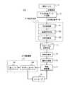
本実施の形態にかかる自律移動ロボット100(以下、単にロボット100と呼ぶ)の自律移動に関する制御系の構成を図1に示す。ロボット100は、脚歩行型の移動ロボットであり、移動機構18として脚リンク181及びこれを駆動するアクチュエータ180を有する。<
FIG. 1 shows the configuration of a control system related to autonomous movement of an autonomous mobile robot 100 (hereinafter simply referred to as robot 100) according to the present embodiment. The
図1において、図1において、視覚センサ11は、ロボット1の外界の距離画像データを取得する。具体的には、レーザレンジファインダ等のアクティブ距離センサによって距離画像データを取得すればよい。なお、CCD(Charge Coupled Device)イメージセンサ又はCMOS(Complementary Metal Oxide Semiconductor)イメージセンサ等の撮像素子を備えた複数のカメラを備え、これら複数のカメラによって撮影した画像データを用いて距離画像データを生成してもよい。具体的には、複数のカメラによって撮影した画像データから対応点を検出し、ステレオ視によって対応点の3次元位置を復元すればよい。ここで、複数の撮影画像における対応点の探索は、複数の撮影画像に対する時空間微分の拘束式を用いた勾配法や相関法等の公知の手法を適用して行えばよい。 In FIG. 1, the visual sensor 11 acquires distance image data of the outside world of the
3次元位置データ生成部12は、距離画像データの座標変換を行って3次元位置データを生成する。なお、3次元位置データとは、距離画像データに含まれる多数の計測点の位置ベクトルを3次元直交座標系で表したデータの集合である。ここで、3次元位置データに含まれる点群の座標は、ロボット100に固定されたロボット座標系で表示されていてもよいし、移動空間に固定されたグローバル座標系で表示されていてもよい。 The three-dimensional position
地図生成部13は、複数のロボット位置で得られた局所的な3次元位置データを統合することにより、広範囲の移動空間に関する環境地図を生成する。本実施の形態のロボット100は脚歩行型であるため、地図生成部13は、足平を着地可能な平面領域の位置を特定可能な環境地図を生成するものとして説明する。また、本実施の形態では、環境地図が、二次元グリッド地図であるとして説明する。 The map generation unit 13 generates an environment map relating to a wide range of movement space by integrating local three-dimensional position data obtained at a plurality of robot positions. Since the
地図生成部13によって生成される環境地図の一例を図2に示す。図2(a)は、ロボット100の移動空間の一例を示している。図2(a)の移動空間160は、床面に相当する平面P11と段差161の上面に相当する平面P12を有している。図2(b)の環境地図200は、図2(a)に示した移動空間160を表す環境地図の一例である。環境地図200は2次元グリッド地図である。環境地図200の各セルは、平面ID、z方向の高さ、法線ベクトルを示す値を保持する。図2(b)において領域R11が平面P11に相当し、領域R12が平面P12に相当する。 An example of the environment map generated by the map generation unit 13 is shown in FIG. FIG. 2A shows an example of the movement space of the
図1に示した地図生成部13は、平面検出部131、信頼度判定部132、及び地図更新部133を含む。以下では、これらの構成要素について順に説明する。 The map generation unit 13 illustrated in FIG. 1 includes a plane detection unit 131, a
平面検出部131は、3次元位置データから平面を検出する。なお、多数の計測点(3次元位置データ)から平面の方程式を表す平面パラメータ(例えば、法線ベクトル及び法線ベクトルの座標系原点からの距離)を検出するために、ハフ変換法やランダムサンプリング法が従来から用いられている。本実施の形態における平面検出には、従来から知られているこれらの手法を適用すればよい。 The plane detection unit 131 detects a plane from the three-dimensional position data. In order to detect plane parameters (for example, normal vectors and distances from the origin of the coordinate system of normal vectors) from a large number of measurement points (three-dimensional position data), the Hough transform method or random sampling is used. The method is conventionally used. Conventionally known methods may be applied to the plane detection in the present embodiment.
信頼度判定部132は、3次元位置データの信頼度を算出する。レーザレンジファインダ等の視覚センサ10によって得られる距離画像データは、ロボット100の揺れや振動によって移動空間の形状を正確に反映してない場合がある。信頼度判定部132は、このような距離画像データの精度低下を3次元位置データの信頼度として算出する。信頼度算出の具体例については後述する。 The
地図更新部133は、異なるロボット位置で得られた複数の3次元位置データを繋ぎ合わせて広範囲の環境地図を作成する。具体的には、地図更新部133は、複数の3次元位置データをオドメトリより推定されるロボット位置及び姿勢に基づいて移動空間に固定されたグローバル座標系に座標変換し、グローバル座標上で連結することによって複数の3次元位置データを統合する。 The
環境地図記憶部14は、地図生成部13により生成された環境地図を記憶する。 The environment map storage unit 14 stores the environment map generated by the map generation unit 13.
移動計画部15は、地図生成部13によって生成された環境地図を参照して目標位置を決定し、決定した目標位置に到達するための脚リンク181の軌道、具体的には、脚リンク181の先端に設けられた足平の着地位置を算出すればよい。 The movement plan unit 15 determines a target position with reference to the environment map generated by the map generation unit 13, and specifically the trajectory of the
動作生成部16は、移動計画部15によって生成された足平の着地位置を実現するための動作データを生成する。ここで、動作データは、例えば、ロボット100のZMP位置、重心位置、足平の位置及び姿勢等を含む。 The motion generation unit 16 generates motion data for realizing the foot landing position generated by the movement planning unit 15. Here, the motion data includes, for example, the ZMP position, the gravity center position, the foot position and posture of the
移動制御部17は、動作生成部16によって生成された動作データを入力し、逆運動学演算によって各関節の目標関節角度を算出する。さらに、移動制御部17は、算出された目標関節角度等の制御目標値とエンコーダ19によって計測される現在の関節角度をもとに各関節を駆動するためのトルク制御値を算出する。移動制御部17によって算出されたトルク制御値に従って、アクチュエータ180が脚リンク181に設けられた関節を駆動することにより、ロボット100の歩行が行われる。 The movement control unit 17 receives the motion data generated by the motion generation unit 16 and calculates a target joint angle of each joint by inverse kinematics calculation. Furthermore, the movement control unit 17 calculates a torque control value for driving each joint based on the control target value such as the calculated target joint angle and the current joint angle measured by the
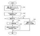
続いて以下では、地図生成部13による環境地図の生成手順について図3〜6を参照して詳細に説明する。図3は、地図生成部13による環境地図の生成手順の具体例を示すフローチャートである。ステップS101では、平面検出部131が、最新(第nフレームとする)の3次元位置データを入力して平面検出を行う。 Next, in the following, a procedure for generating an environmental map by the map generation unit 13 will be described in detail with reference to FIGS. FIG. 3 is a flowchart showing a specific example of the environmental map generation procedure by the map generation unit 13. In step S101, the plane detection unit 131 inputs the latest (assumed to be the nth frame) three-dimensional position data and performs plane detection.
ステップS102では、信頼度判定部132が、最新の3次元位置データの信頼度を算出する。また、ステップS103では、信頼度判定部132が、算出された信頼度が予め定められた基準を満足しているか否かを判定する。 In step S102, the
ここで、3次元位置データの信頼度の具体例について説明する。最新の3次元位置データの信頼度判定には、例えば、以下の(1)〜(3)の基準を用いればよい。
(1)前記過去の3次元位置データから検出された平面の位置及び前記移動ロボットの移動量を用いて算出される推定位置と、前記新たな3次元位置データから検出された平面の位置との一致度合い。
(2)前記過去の3次元位置データより検出された平面を規定する平面パラメータと、前記新たな3次元位置データより検出された平面を規定する平面パラメータとの一致度合い。
(3)前記新たな3次元位置データを最小二乗法によって平面にフィッティングする際の最小二乗誤差が、予め定められた基準値より小さいこと。Here, a specific example of the reliability of the three-dimensional position data will be described. For the reliability determination of the latest three-dimensional position data, for example, the following criteria (1) to (3) may be used.
(1) An estimated position calculated using the position of the plane detected from the past three-dimensional position data and the amount of movement of the mobile robot, and the position of the plane detected from the new three-dimensional position data The degree of match.
(2) A degree of coincidence between a plane parameter that defines a plane detected from the past three-dimensional position data and a plane parameter that defines a plane detected from the new three-dimensional position data.
(3) A least square error when fitting the new three-dimensional position data to a plane by the least square method is smaller than a predetermined reference value.
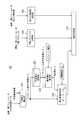
図4は、上述の基準(1)〜(3)により信頼度判定を行う信頼度判定部132の構成例を示すブロック図である。図4において、平面重心算出部1321、平面重心記憶部1322、推定重心算出部1323、及び重心距離判定部1324は、上述の基準(1)による信頼度判定を行うための構成要素である。 FIG. 4 is a block diagram illustrating a configuration example of the
平面重心算出部1321は、最新(第nフレーム)の3次元位置データと平面検出部131による平面検出結果とを入力し、検出された平面の重心Cnを算出する。ここで、平面の重心とは、平面と認識された3次元位置データ中の複数の点群の重心を意味する。The plane
平面重心記憶部1322は、平面重心算出部1321によって算出される平面重心Cnを記憶する。The plane
推定重心算出部1323は、1フレーム前、すなわち第n−1フレームの平面重心Cn−1を平面重心記憶部1322から読み出し、平面重心Cn−1及びロボット100のオドメトリ情報を用いて推定重心Sを算出する。ここで、推定重心Sとは、1フレーム前の平面重心Cn−1を、ロボット100の移動量に応じて移動させることによって得られる最新の平面重心Cnの予想位置である。図5(a)は、過去の第n−1フレームにおける平面P12の重心位置Cn−1と、推定重心Sを示す概念図である。一方、図5(b)は、最新の第nフレームにおける平面P12の重心位置Cnを示す概念図である。Estimating the center of
重心距離判定部1324は、最新の平面重心Cnと推定重心Sとの距離が予め定められた距離閾値DTH未満であるかによって、基準(1)の充足を判定する。例えば、図5(a)及び(b)のように、最新の平面重心Cnと推定重心Sとが一致する場合は、基準(1)を充足すると判定される。The center-of-gravity
一方、図4の平面パラメータ比較部1325は、上述の基準(2)による信頼度判定を行う。具体的には、平面パラメータ比較部1325は、第nフレームの平面パラメータと第n−1フレームの平面パラメータを比較し、これらの差が予め定められた範囲内であるか否かを判定する。 On the other hand, the plane
また、図4の最小二乗誤差判定部1326は、上述の基準(3)による信頼度判定を行う。具体的には、最小二乗誤差判定部1326は、第nフレームの最小二乗法誤差が予め定められた基準値より小さいか否かを判定する。ここで、第nフレームの最小二乗法誤差とは、平面検出部131において、第nフレームの3次元位置データに含まれる点群の平面フィッティングを最小二乗法により行なった場合における、距離の二乗和の最小値である。 Further, the least square
最後に、総合判定部1327は、上述した基準(1)〜(3)の全てを満足する場合に、第nフレームの3次元位置データが所定の信頼度を満足するものと判定する。 Finally, the
なお、上述した基準(1)〜(3)は、3次元位置データの信頼度の一例に過ぎないことはもちろんである。例えば、基準(1)〜(3)のうち少なくとも1つを用いて信頼度を評価してもよい。 Of course, the criteria (1) to (3) described above are merely examples of the reliability of the three-dimensional position data. For example, the reliability may be evaluated using at least one of criteria (1) to (3).
図3のフローチャートに戻り説明を続ける。ステップS103の信頼度判定において、算出された信頼度が予め定められた基準を満足していると判定された場合(S103でOK)、地図更新部133は第nフレームの3次元位置データの補間処理を行う(ステップS104)。具体的には、視覚センサ10の通信エラー等に起因して第nフレームの3次元位置データに含まれる点群にデータ抜けがある場合や、視覚センサ10の空間分解能が低いために3次元位置データの点群密度が疎である場合に、データ抜けのある領域や密度が疎な領域を周囲の点群データによって補間する。当該補間処理は、線形補間などの公知のデータ補間手法を用いて行なえばよい。 Returning to the flowchart of FIG. If it is determined in the reliability determination in step S103 that the calculated reliability satisfies a predetermined criterion (OK in S103), the
ステップS105では、地図更新部133が、最新の第nフレームの3次元位置データを旧環境地図に上書きして新たな環境地図を生成する。すなわち、地図更新部133は、最新の第nフレームの3次元位置データの測定領域と重複している旧環境地図の領域内のデータを破棄し、第nフレームの平面データと置き換える。 In step S105, the
例えば、図6(a)に示すように、旧環境地図が第(n−1)〜(n−k)フレームまでの過去のk枚のフレームを統合して生成されている場合を考える。旧環境地図は、段差の上面に相当する平面P12を含む。最新の第nフレーム内に平面P12の一部である部分61が含まれる場合、ステップS105の処理によって、部分61に対応する新環境地図上の領域が、最新(第nフレーム)の3次元位置データ、平面検出結果により上書きされる。 For example, as shown in FIG. 6A, consider a case where the old environment map is generated by integrating the past k frames from the (n−1) th to (n−k) th frames. The old environment map includes a plane P12 corresponding to the upper surface of the step. When the latest n-th frame includes a
さらに、図6(b)は、図6(a)に引き続く第(n+1)フレームの処理を示している。平面P12の部分61のさらに一部にあたる部分62が最新の第(n+1)フレーム内に含まれる場合、ステップS105の処理によって、部分62に対応する新環境地図上の領域が、第(n+1)フレームの3次元位置データ、平面検出結果により上書きされる。 Further, FIG. 6B shows the processing of the (n + 1) th frame following FIG. 6A. When the
一方、ステップS103の信頼度判定において、算出された信頼度が予め定められた基準を満足しないと判定された場合(S103でNG)、第nフレームの3次元位置データを破棄し、第n−1フレームまでの3次元位置データを統合して生成された環境地図を維持する。 On the other hand, when it is determined in the reliability determination in step S103 that the calculated reliability does not satisfy a predetermined criterion (NG in S103), the three-dimensional position data of the nth frame is discarded, and the nth− An environmental map generated by integrating three-dimensional position data up to one frame is maintained.
上述したステップS105の処理、すなわち、過去の3次元位置データを元に生成された環境地図の領域を最新の3次元位置データによって上書きする処理によって、段差等のエッジが不明瞭となる弊害を防止し、エッジが精細に特定された環境地図を得ることができる。 The above-described processing in step S105, that is, the processing of overwriting the area of the environmental map generated based on the past three-dimensional position data with the latest three-dimensional position data, prevents the adverse effect of making the edge of the step or the like unclear. In addition, it is possible to obtain an environmental map in which the edges are specified in detail.
また、最新フレームの3次元位置データに含まれない領域については、過去に取得された3次元位置データに基づいて生成された環境地図を利用して移動計画を行うことができるため、広範囲な移動空間に関して移動計画を実行することができる。 In addition, a region that is not included in the 3D position data of the latest frame can be traveled using an environmental map generated based on the 3D position data acquired in the past. A travel plan can be executed on the space.
さらに、上述したステップS106の処理、すなわち、信頼度の低い3次元位置データを環境地図に反映させないことによって、環境地図の精度低下を防止できる。 Further, the accuracy of the environmental map can be prevented from being reduced by not reflecting the process of step S106 described above, that is, the three-dimensional position data with low reliability on the environmental map.
<その他の実施の形態>
発明の実施の形態1では、脚歩行型のロボット100に本願発明を適用した例を示した。しかしながら、ロボット100が車輪走行型などの脚歩行型以外の移動ロボットであってもよいことは勿論である。<Other embodiments>
In the first embodiment of the invention, an example in which the present invention is applied to the leg-walking
また、発明の実施の形態1では、環境地図が平面検出結果を保持するグリッド地図であるとして説明したが、このような環境地図は一例である。例えば、環境地図は、ロボット100が移動可能であるか、あるいは障害物の存在により移動不可能であるかを識別する値が各セルに保持されるグリッド地図でもよい。この場合、地図生成部13は、3次元位置データから障害物を検出できればよく、平面検出処理は必ずしも行う必要がない。また、このとき、3次元位置データの信頼度は、過去の3次元位置データに基づく障害物の推定位置と、最新の第nフレームにおける障害物位置との一致度合いを利用して評価すればよい。 Moreover, although
また、発明の実施の形態1では、環境地図が二次元のグリッド地図であるとして説明を行なった。しかしながら、環境地図は、三次元のグリッド地図でもよい。 In the first embodiment of the present invention, the environment map is described as a two-dimensional grid map. However, the environment map may be a three-dimensional grid map.
さらに、本発明は上述した実施の形態のみに限定されるものではなく、既に述べた本発明の要旨を逸脱しない範囲において種々の変更が可能であることは勿論である。 Furthermore, the present invention is not limited to the above-described embodiments, and various modifications can be made without departing from the gist of the present invention described above.
100 移動ロボット
11 視覚センサ
12 3次元位置データ生成部
13 地図生成部
131 平面検出部
132 信頼度判定部
133 地図更新部
14 環境地図記憶部
15 移動計画部
16 動作生成部
17 移動制御部
18 移動機構
180 アクチュエータ
181 脚リンク
19 エンコーダDESCRIPTION OF
Claims (7)
Translated fromJapanese前記移動空間を視覚的に認識する視覚センサと、
前記視覚センサによる計測結果を用いて、前記移動空間に存在する計測対象の位置を示す3次元位置データを生成する3次元位置データ生成部と、
異なるロボット位置で計測された複数の前記3次元位置データを統合することにより、前記移動空間に関する環境地図を生成する環境地図生成部とを備え、
前記環境地図生成部は、前記3次元位置データ生成部によって生成された新たな3次元位置データが予め定められた信頼度を有する場合に、前記新たな3次元位置データと重複する過去の環境地図内の領域を、前記新たな3次元位置データで上書き更新することによって新たな環境地図を生成する、
移動ロボット。A mobile robot that moves in a moving space with reference to an environmental map,
A visual sensor for visually recognizing the moving space;
A three-dimensional position data generation unit that generates three-dimensional position data indicating the position of the measurement target existing in the movement space, using the measurement result of the visual sensor;
An environment map generation unit that generates an environment map related to the moving space by integrating a plurality of the three-dimensional position data measured at different robot positions;
The environment map generation unit includes a past environment map that overlaps with the new 3D position data when the new 3D position data generated by the 3D position data generation unit has a predetermined reliability. A new environment map is generated by overwriting and updating the area in the area with the new three-dimensional position data.
Mobile robot.
視覚センサによる計測結果を用いて、前記移動ロボットの移動空間に存在する計測対象の位置を示す3次元位置データを生成するステップ(a)と、
異なるロボット位置で計測された複数の前記3次元位置データを統合することにより、前記移動空間に関する環境地図を生成するステップ(b)とを備え、
前記ステップ(b)では、新たな3次元位置データが予め定められた信頼度を有する場合に、前記新たな3次元位置データと重複する過去の環境地図内の領域を、前記新たな3次元位置データで上書き更新することによって新たな環境地図を生成する、
環境地図の生成方法。A method for generating an environmental map to be referenced for movement of a mobile robot,
(A) generating three-dimensional position data indicating a position of a measurement target existing in a movement space of the mobile robot using a measurement result by a visual sensor;
(B) generating an environmental map related to the moving space by integrating a plurality of the three-dimensional position data measured at different robot positions;
In the step (b), when the new three-dimensional position data has a predetermined reliability, an area in the past environmental map that overlaps with the new three-dimensional position data is changed to the new three-dimensional position data. Create a new environmental map by overwriting with data,
How to create an environmental map.
Priority Applications (1)
| Application Number | Priority Date | Filing Date | Title |
|---|---|---|---|
| JP2008032010AJP2009193240A (en) | 2008-02-13 | 2008-02-13 | Mobile robot and environmental map generation method |
Applications Claiming Priority (1)
| Application Number | Priority Date | Filing Date | Title |
|---|---|---|---|
| JP2008032010AJP2009193240A (en) | 2008-02-13 | 2008-02-13 | Mobile robot and environmental map generation method |
Publications (1)
| Publication Number | Publication Date |
|---|---|
| JP2009193240Atrue JP2009193240A (en) | 2009-08-27 |
Family
ID=41075208
Family Applications (1)
| Application Number | Title | Priority Date | Filing Date |
|---|---|---|---|
| JP2008032010APendingJP2009193240A (en) | 2008-02-13 | 2008-02-13 | Mobile robot and environmental map generation method |
Country Status (1)
| Country | Link |
|---|---|
| JP (1) | JP2009193240A (en) |
Cited By (60)
| Publication number | Priority date | Publication date | Assignee | Title |
|---|---|---|---|---|
| WO2011055711A1 (en)* | 2009-11-06 | 2011-05-12 | 株式会社日立製作所 | Mobile robot system |
| WO2011078264A1 (en)* | 2009-12-25 | 2011-06-30 | 本田技研工業株式会社 | Image processing apparatus, image processing method, computer program, and mobile body |
| JP2012103819A (en)* | 2010-11-08 | 2012-05-31 | Fujitsu Ltd | Position estimation method, position estimation device and program |
| JP2014203145A (en)* | 2013-04-02 | 2014-10-27 | パナソニック株式会社 | Autonomous mobile apparatus |
| JP2015521880A (en)* | 2012-06-27 | 2015-08-03 | コーニンクレッカ フィリップス エヌ ヴェ | Motion parameter estimation |
| JP2016045330A (en)* | 2014-08-22 | 2016-04-04 | 株式会社Ihi | Method and device for aligning three-dimensional point group data and mobile body system thereof |
| WO2016094013A1 (en)* | 2014-12-11 | 2016-06-16 | Toyota Motor Engineering & Manufacturing North America, Inc. | Visual-assist robots |
| JP2016124401A (en)* | 2014-12-26 | 2016-07-11 | アイシン精機株式会社 | Parking assistance device |
| JP2016180797A (en)* | 2015-03-23 | 2016-10-13 | 株式会社豊田中央研究所 | Road information generation device and program |
| JP2017003363A (en)* | 2015-06-08 | 2017-01-05 | 株式会社パスコ | Position estimation method, position estimation device, and position estimation program |
| JP2017501474A (en)* | 2013-12-19 | 2017-01-12 | アクチエボラゲット エレクトロルックス | Robot vacuum cleaner and landmark recognition method |
| JP2017111688A (en)* | 2015-12-17 | 2017-06-22 | カシオ計算機株式会社 | Autonomous mobile device, autonomous mobile method, and program |
| WO2017169598A1 (en)* | 2016-03-30 | 2017-10-05 | 株式会社小松製作所 | Terminal device, control device, data integration device, work vehicle, image-capturing system, and image-capturing method |
| JP2017186870A (en)* | 2016-03-30 | 2017-10-12 | 株式会社小松製作所 | Terminal device, control device, data integration device, work vehicle, imaging system, and imaging method |
| US9811089B2 (en) | 2013-12-19 | 2017-11-07 | Aktiebolaget Electrolux | Robotic cleaning device with perimeter recording function |
| JP2018017826A (en)* | 2016-07-26 | 2018-02-01 | 株式会社豊田中央研究所 | Autonomous moving body and environment map update device |
| WO2018038131A1 (en)* | 2016-08-26 | 2018-03-01 | パナソニック インテレクチュアル プロパティ コーポレーション オブ アメリカ | Three-dimensional information processing method and three-dimensional information processing apparatus |
| US9939529B2 (en) | 2012-08-27 | 2018-04-10 | Aktiebolaget Electrolux | Robot positioning system |
| US9946263B2 (en) | 2013-12-19 | 2018-04-17 | Aktiebolaget Electrolux | Prioritizing cleaning areas |
| WO2018131165A1 (en)* | 2017-01-16 | 2018-07-19 | 富士通株式会社 | Information processing program, information processing method, and information processing device |
| US10045675B2 (en) | 2013-12-19 | 2018-08-14 | Aktiebolaget Electrolux | Robotic vacuum cleaner with side brush moving in spiral pattern |
| CN108475059A (en)* | 2015-12-15 | 2018-08-31 | 高通股份有限公司 | Autonomous vision guided navigation |
| CN108664019A (en)* | 2017-03-27 | 2018-10-16 | 卡西欧计算机株式会社 | Autonomous device, autonomous method and computer-readable recording medium |
| US10108199B2 (en) | 2015-12-10 | 2018-10-23 | Casio Computer Co., Ltd. | Autonomous movement device, autonomous movement method and non-transitory recording medium |
| US10149589B2 (en) | 2013-12-19 | 2018-12-11 | Aktiebolaget Electrolux | Sensing climb of obstacle of a robotic cleaning device |
| US10209080B2 (en) | 2013-12-19 | 2019-02-19 | Aktiebolaget Electrolux | Robotic cleaning device |
| US10219665B2 (en) | 2013-04-15 | 2019-03-05 | Aktiebolaget Electrolux | Robotic vacuum cleaner with protruding sidebrush |
| US10231591B2 (en) | 2013-12-20 | 2019-03-19 | Aktiebolaget Electrolux | Dust container |
| US10296009B2 (en) | 2015-12-16 | 2019-05-21 | Casio Computer Co., Ltd. | Autonomous movement device, autonomous movement method and non-transitory recording medium |
| US10296002B2 (en) | 2016-03-14 | 2019-05-21 | Casio Computer Co., Ltd. | Autonomous movement device, autonomous movement method, and non-transitory recording medium |
| JP2019109653A (en)* | 2017-12-18 | 2019-07-04 | パイオニア株式会社 | Self-location estimating apparatus |
| JP2019109331A (en)* | 2017-12-18 | 2019-07-04 | パイオニア株式会社 | Map data structure |
| JP2019109332A (en)* | 2017-12-18 | 2019-07-04 | パイオニア株式会社 | Map data structure |
| JP2019145077A (en)* | 2017-12-15 | 2019-08-29 | バイドゥ ユーエスエイ エルエルシーBaidu USA LLC | System for building vehicle-to-cloud real-time traffic map for autonomous driving vehicle (adv) |
| US10433697B2 (en) | 2013-12-19 | 2019-10-08 | Aktiebolaget Electrolux | Adaptive speed control of rotating side brush |
| US10448794B2 (en) | 2013-04-15 | 2019-10-22 | Aktiebolaget Electrolux | Robotic vacuum cleaner |
| US10499778B2 (en) | 2014-09-08 | 2019-12-10 | Aktiebolaget Electrolux | Robotic vacuum cleaner |
| US10518416B2 (en) | 2014-07-10 | 2019-12-31 | Aktiebolaget Electrolux | Method for detecting a measurement error in a robotic cleaning device |
| US10534367B2 (en) | 2014-12-16 | 2020-01-14 | Aktiebolaget Electrolux | Experience-based roadmap for a robotic cleaning device |
| JP2020020694A (en)* | 2018-08-01 | 2020-02-06 | トヨタ自動車株式会社 | Axis deviation detector and vehicle |
| US10678251B2 (en) | 2014-12-16 | 2020-06-09 | Aktiebolaget Electrolux | Cleaning method for a robotic cleaning device |
| US10729297B2 (en) | 2014-09-08 | 2020-08-04 | Aktiebolaget Electrolux | Robotic vacuum cleaner |
| JP2020525809A (en)* | 2018-06-14 | 2020-08-27 | ベイジン ディディ インフィニティ テクノロジー アンド ディベロップメント カンパニー リミティッド | System and method for updating high resolution maps based on binocular images |
| US10874271B2 (en) | 2014-12-12 | 2020-12-29 | Aktiebolaget Electrolux | Side brush and robotic cleaner |
| US10874274B2 (en) | 2015-09-03 | 2020-12-29 | Aktiebolaget Electrolux | System of robotic cleaning devices |
| US10877484B2 (en) | 2014-12-10 | 2020-12-29 | Aktiebolaget Electrolux | Using laser sensor for floor type detection |
| US11003939B2 (en) | 2018-07-06 | 2021-05-11 | Canon Kabushiki Kaisha | Information processing apparatus, information processing method, and storage medium |
| US11099554B2 (en) | 2015-04-17 | 2021-08-24 | Aktiebolaget Electrolux | Robotic cleaning device and a method of controlling the robotic cleaning device |
| US11122953B2 (en) | 2016-05-11 | 2021-09-21 | Aktiebolaget Electrolux | Robotic cleaning device |
| CN113494916A (en)* | 2020-04-01 | 2021-10-12 | 杭州萤石软件有限公司 | Map construction method and multi-legged robot |
| US11169533B2 (en) | 2016-03-15 | 2021-11-09 | Aktiebolaget Electrolux | Robotic cleaning device and a method at the robotic cleaning device of performing cliff detection |
| JP2022079622A (en)* | 2017-12-18 | 2022-05-26 | ジオテクノロジーズ株式会社 | Self position estimation device and vehicle position estimation system |
| US11423005B2 (en) | 2017-04-03 | 2022-08-23 | Mitsubishi Electric Corporation | Map data generator and method for generating map data |
| US11474533B2 (en) | 2017-06-02 | 2022-10-18 | Aktiebolaget Electrolux | Method of detecting a difference in level of a surface in front of a robotic cleaning device |
| JP2023081085A (en)* | 2021-11-30 | 2023-06-09 | オムロン株式会社 | Travel unit and method for controlling travel unit |
| JP2023122807A (en)* | 2022-02-24 | 2023-09-05 | 日立グローバルライフソリューションズ株式会社 | Autonomous travel type robot |
| JP2023178652A (en)* | 2022-06-06 | 2023-12-18 | Kddi株式会社 | Three-dimensional map creation system, method, and program |
| US11921517B2 (en) | 2017-09-26 | 2024-03-05 | Aktiebolaget Electrolux | Controlling movement of a robotic cleaning device |
| CN118482684A (en)* | 2024-05-11 | 2024-08-13 | 国网江苏省电力有限公司泰州供电分公司 | A method, device and system for obtaining elevation information based on vision |
| CN118823275A (en)* | 2024-09-18 | 2024-10-22 | 湖南理工职业技术学院 | A method for modeling and positioning an augmented reality environment for a mobile robot |
- 2008
- 2008-02-13JPJP2008032010Apatent/JP2009193240A/enactivePending
Cited By (92)
| Publication number | Priority date | Publication date | Assignee | Title |
|---|---|---|---|---|
| WO2011055711A1 (en)* | 2009-11-06 | 2011-05-12 | 株式会社日立製作所 | Mobile robot system |
| JP5270767B2 (en)* | 2009-11-06 | 2013-08-21 | 株式会社日立製作所 | Mobile robot system |
| WO2011078264A1 (en)* | 2009-12-25 | 2011-06-30 | 本田技研工業株式会社 | Image processing apparatus, image processing method, computer program, and mobile body |
| JPWO2011078264A1 (en)* | 2009-12-25 | 2013-05-09 | 本田技研工業株式会社 | Image processing apparatus, image processing method, computer program, and moving body |
| US9488721B2 (en) | 2009-12-25 | 2016-11-08 | Honda Motor Co., Ltd. | Image processing apparatus, image processing method, computer program, and movable body |
| JP2012103819A (en)* | 2010-11-08 | 2012-05-31 | Fujitsu Ltd | Position estimation method, position estimation device and program |
| JP2015521880A (en)* | 2012-06-27 | 2015-08-03 | コーニンクレッカ フィリップス エヌ ヴェ | Motion parameter estimation |
| US9939529B2 (en) | 2012-08-27 | 2018-04-10 | Aktiebolaget Electrolux | Robot positioning system |
| JP2014203145A (en)* | 2013-04-02 | 2014-10-27 | パナソニック株式会社 | Autonomous mobile apparatus |
| US10448794B2 (en) | 2013-04-15 | 2019-10-22 | Aktiebolaget Electrolux | Robotic vacuum cleaner |
| US10219665B2 (en) | 2013-04-15 | 2019-03-05 | Aktiebolaget Electrolux | Robotic vacuum cleaner with protruding sidebrush |
| US10149589B2 (en) | 2013-12-19 | 2018-12-11 | Aktiebolaget Electrolux | Sensing climb of obstacle of a robotic cleaning device |
| US10433697B2 (en) | 2013-12-19 | 2019-10-08 | Aktiebolaget Electrolux | Adaptive speed control of rotating side brush |
| JP2017501474A (en)* | 2013-12-19 | 2017-01-12 | アクチエボラゲット エレクトロルックス | Robot vacuum cleaner and landmark recognition method |
| US10617271B2 (en) | 2013-12-19 | 2020-04-14 | Aktiebolaget Electrolux | Robotic cleaning device and method for landmark recognition |
| US10209080B2 (en) | 2013-12-19 | 2019-02-19 | Aktiebolaget Electrolux | Robotic cleaning device |
| US9811089B2 (en) | 2013-12-19 | 2017-11-07 | Aktiebolaget Electrolux | Robotic cleaning device with perimeter recording function |
| US10045675B2 (en) | 2013-12-19 | 2018-08-14 | Aktiebolaget Electrolux | Robotic vacuum cleaner with side brush moving in spiral pattern |
| US9946263B2 (en) | 2013-12-19 | 2018-04-17 | Aktiebolaget Electrolux | Prioritizing cleaning areas |
| US10231591B2 (en) | 2013-12-20 | 2019-03-19 | Aktiebolaget Electrolux | Dust container |
| US10518416B2 (en) | 2014-07-10 | 2019-12-31 | Aktiebolaget Electrolux | Method for detecting a measurement error in a robotic cleaning device |
| JP2016045330A (en)* | 2014-08-22 | 2016-04-04 | 株式会社Ihi | Method and device for aligning three-dimensional point group data and mobile body system thereof |
| US10499778B2 (en) | 2014-09-08 | 2019-12-10 | Aktiebolaget Electrolux | Robotic vacuum cleaner |
| US10729297B2 (en) | 2014-09-08 | 2020-08-04 | Aktiebolaget Electrolux | Robotic vacuum cleaner |
| US10877484B2 (en) | 2014-12-10 | 2020-12-29 | Aktiebolaget Electrolux | Using laser sensor for floor type detection |
| US9530058B2 (en)* | 2014-12-11 | 2016-12-27 | Toyota Motor Engineering & Manufacturing North America, Inc. | Visual-assist robots |
| WO2016094013A1 (en)* | 2014-12-11 | 2016-06-16 | Toyota Motor Engineering & Manufacturing North America, Inc. | Visual-assist robots |
| US10874271B2 (en) | 2014-12-12 | 2020-12-29 | Aktiebolaget Electrolux | Side brush and robotic cleaner |
| US10678251B2 (en) | 2014-12-16 | 2020-06-09 | Aktiebolaget Electrolux | Cleaning method for a robotic cleaning device |
| US10534367B2 (en) | 2014-12-16 | 2020-01-14 | Aktiebolaget Electrolux | Experience-based roadmap for a robotic cleaning device |
| JP2016124401A (en)* | 2014-12-26 | 2016-07-11 | アイシン精機株式会社 | Parking assistance device |
| JP2016180797A (en)* | 2015-03-23 | 2016-10-13 | 株式会社豊田中央研究所 | Road information generation device and program |
| US11099554B2 (en) | 2015-04-17 | 2021-08-24 | Aktiebolaget Electrolux | Robotic cleaning device and a method of controlling the robotic cleaning device |
| JP2017003363A (en)* | 2015-06-08 | 2017-01-05 | 株式会社パスコ | Position estimation method, position estimation device, and position estimation program |
| US10874274B2 (en) | 2015-09-03 | 2020-12-29 | Aktiebolaget Electrolux | System of robotic cleaning devices |
| US11712142B2 (en) | 2015-09-03 | 2023-08-01 | Aktiebolaget Electrolux | System of robotic cleaning devices |
| US10108199B2 (en) | 2015-12-10 | 2018-10-23 | Casio Computer Co., Ltd. | Autonomous movement device, autonomous movement method and non-transitory recording medium |
| JP2019500693A (en)* | 2015-12-15 | 2019-01-10 | クゥアルコム・インコーポレイテッドQualcomm Incorporated | Autonomous visual navigation |
| CN108475059A (en)* | 2015-12-15 | 2018-08-31 | 高通股份有限公司 | Autonomous vision guided navigation |
| CN108475059B (en)* | 2015-12-15 | 2021-11-09 | 高通股份有限公司 | Autonomous visual navigation |
| US10296009B2 (en) | 2015-12-16 | 2019-05-21 | Casio Computer Co., Ltd. | Autonomous movement device, autonomous movement method and non-transitory recording medium |
| CN106896807A (en)* | 2015-12-17 | 2017-06-27 | 卡西欧计算机株式会社 | Autonomous device and autonomous method |
| CN106896807B (en)* | 2015-12-17 | 2020-02-28 | 卡西欧计算机株式会社 | Autonomous mobile device, autonomous mobile method, and recording medium |
| JP2017111688A (en)* | 2015-12-17 | 2017-06-22 | カシオ計算機株式会社 | Autonomous mobile device, autonomous mobile method, and program |
| US10012989B2 (en) | 2015-12-17 | 2018-07-03 | Casio Computer Co., Ltd. | Autonomous movement device, autonomous movement method and non-transitory recording medium |
| US10296002B2 (en) | 2016-03-14 | 2019-05-21 | Casio Computer Co., Ltd. | Autonomous movement device, autonomous movement method, and non-transitory recording medium |
| US11169533B2 (en) | 2016-03-15 | 2021-11-09 | Aktiebolaget Electrolux | Robotic cleaning device and a method at the robotic cleaning device of performing cliff detection |
| WO2017169598A1 (en)* | 2016-03-30 | 2017-10-05 | 株式会社小松製作所 | Terminal device, control device, data integration device, work vehicle, image-capturing system, and image-capturing method |
| US10805597B2 (en) | 2016-03-30 | 2020-10-13 | Komatsu Ltd. | Terminal device, control device, data-integrating device, work vehicle, image-capturing system, and image-capturing method |
| JP2017186870A (en)* | 2016-03-30 | 2017-10-12 | 株式会社小松製作所 | Terminal device, control device, data integration device, work vehicle, imaging system, and imaging method |
| US20190020867A1 (en)* | 2016-03-30 | 2019-01-17 | Komatsu Ltd. | Terminal device, control device, data-integrating device, work vehicle, image-capturing system, and image-capturing method |
| US11122953B2 (en) | 2016-05-11 | 2021-09-21 | Aktiebolaget Electrolux | Robotic cleaning device |
| JP2018017826A (en)* | 2016-07-26 | 2018-02-01 | 株式会社豊田中央研究所 | Autonomous moving body and environment map update device |
| JPWO2018038131A1 (en)* | 2016-08-26 | 2019-06-24 | パナソニック インテレクチュアル プロパティ コーポレーション オブ アメリカPanasonic Intellectual Property Corporation of America | Three-dimensional information processing method and three-dimensional information processing apparatus |
| JP2023026501A (en)* | 2016-08-26 | 2023-02-24 | パナソニック インテレクチュアル プロパティ コーポレーション オブ アメリカ | Three-dimensional information processing method and three-dimensional information processing apparatus |
| WO2018038131A1 (en)* | 2016-08-26 | 2018-03-01 | パナソニック インテレクチュアル プロパティ コーポレーション オブ アメリカ | Three-dimensional information processing method and three-dimensional information processing apparatus |
| JP7307259B2 (en) | 2016-08-26 | 2023-07-11 | パナソニック インテレクチュアル プロパティ コーポレーション オブ アメリカ | Three-dimensional information processing method and three-dimensional information processing apparatus |
| US12367769B2 (en) | 2016-08-26 | 2025-07-22 | Panasonic Intellectual Property Corporation Of America | Three-dimensional information processing method and three-dimensional information processing device |
| US11790779B2 (en) | 2016-08-26 | 2023-10-17 | Panasonic Intellectual Property Corporation Of America | Three-dimensional information processing method and three-dimensional information processing device |
| JP2022103160A (en)* | 2016-08-26 | 2022-07-07 | パナソニック インテレクチュアル プロパティ コーポレーション オブ アメリカ | Three-dimensional information processing method and three-dimensional information processing device |
| JP7050683B2 (en) | 2016-08-26 | 2022-04-08 | パナソニック インテレクチュアル プロパティ コーポレーション オブ アメリカ | 3D information processing method and 3D information processing equipment |
| US11410552B2 (en) | 2016-08-26 | 2022-08-09 | Panasonic Intellectual Property Corporation Of America | Three-dimensional information processing method and three-dimensional information processing device |
| US10885357B2 (en) | 2017-01-16 | 2021-01-05 | Fujitsu Limited | Recording medium recording information processing program, information processing method, and information processing apparatus |
| JPWO2018131165A1 (en)* | 2017-01-16 | 2019-11-07 | 富士通株式会社 | Information processing program, information processing method, and information processing apparatus |
| WO2018131165A1 (en)* | 2017-01-16 | 2018-07-19 | 富士通株式会社 | Information processing program, information processing method, and information processing device |
| CN108664019A (en)* | 2017-03-27 | 2018-10-16 | 卡西欧计算机株式会社 | Autonomous device, autonomous method and computer-readable recording medium |
| US11054837B2 (en) | 2017-03-27 | 2021-07-06 | Casio Computer Co., Ltd. | Autonomous mobile apparatus adaptable to change in height, autonomous movement method and non-transitory computer-readable recording medium |
| JP2018163614A (en)* | 2017-03-27 | 2018-10-18 | カシオ計算機株式会社 | Autonomous mobile device, autonomous mobile method and program |
| US11423005B2 (en) | 2017-04-03 | 2022-08-23 | Mitsubishi Electric Corporation | Map data generator and method for generating map data |
| US11474533B2 (en) | 2017-06-02 | 2022-10-18 | Aktiebolaget Electrolux | Method of detecting a difference in level of a surface in front of a robotic cleaning device |
| US11921517B2 (en) | 2017-09-26 | 2024-03-05 | Aktiebolaget Electrolux | Controlling movement of a robotic cleaning device |
| JP7030044B2 (en) | 2017-12-15 | 2022-03-04 | バイドゥ ユーエスエイ エルエルシー | A system for building real-time traffic maps between vehicles and the cloud for autonomous vehicles (ADVs) |
| JP2019145077A (en)* | 2017-12-15 | 2019-08-29 | バイドゥ ユーエスエイ エルエルシーBaidu USA LLC | System for building vehicle-to-cloud real-time traffic map for autonomous driving vehicle (adv) |
| JP2019109331A (en)* | 2017-12-18 | 2019-07-04 | パイオニア株式会社 | Map data structure |
| JP2022079622A (en)* | 2017-12-18 | 2022-05-26 | ジオテクノロジーズ株式会社 | Self position estimation device and vehicle position estimation system |
| JP7216233B2 (en) | 2017-12-18 | 2023-01-31 | ジオテクノロジーズ株式会社 | Self-position estimation device and vehicle position estimation system |
| JP2019109653A (en)* | 2017-12-18 | 2019-07-04 | パイオニア株式会社 | Self-location estimating apparatus |
| JP7251918B2 (en) | 2017-12-18 | 2023-04-04 | ジオテクノロジーズ株式会社 | Vehicle position estimation device and vehicle position estimation system |
| JP7051416B2 (en) | 2017-12-18 | 2022-04-11 | ジオテクノロジーズ株式会社 | Self-position estimation device |
| JP2019109332A (en)* | 2017-12-18 | 2019-07-04 | パイオニア株式会社 | Map data structure |
| JP2020525809A (en)* | 2018-06-14 | 2020-08-27 | ベイジン ディディ インフィニティ テクノロジー アンド ディベロップメント カンパニー リミティッド | System and method for updating high resolution maps based on binocular images |
| US11003939B2 (en) | 2018-07-06 | 2021-05-11 | Canon Kabushiki Kaisha | Information processing apparatus, information processing method, and storage medium |
| US11830216B2 (en) | 2018-07-06 | 2023-11-28 | Canon Kabushiki Kaisha | Information processing apparatus, information processing method, and storage medium |
| JP2020020694A (en)* | 2018-08-01 | 2020-02-06 | トヨタ自動車株式会社 | Axis deviation detector and vehicle |
| JP7119724B2 (en) | 2018-08-01 | 2022-08-17 | トヨタ自動車株式会社 | Shaft deviation detector and vehicle |
| CN113494916A (en)* | 2020-04-01 | 2021-10-12 | 杭州萤石软件有限公司 | Map construction method and multi-legged robot |
| JP2023081085A (en)* | 2021-11-30 | 2023-06-09 | オムロン株式会社 | Travel unit and method for controlling travel unit |
| JP2023122807A (en)* | 2022-02-24 | 2023-09-05 | 日立グローバルライフソリューションズ株式会社 | Autonomous travel type robot |
| JP2023178652A (en)* | 2022-06-06 | 2023-12-18 | Kddi株式会社 | Three-dimensional map creation system, method, and program |
| JP7664886B2 (en) | 2022-06-06 | 2025-04-18 | Kddi株式会社 | 3D map creation device, method and program |
| CN118482684A (en)* | 2024-05-11 | 2024-08-13 | 国网江苏省电力有限公司泰州供电分公司 | A method, device and system for obtaining elevation information based on vision |
| CN118823275A (en)* | 2024-09-18 | 2024-10-22 | 湖南理工职业技术学院 | A method for modeling and positioning an augmented reality environment for a mobile robot |
Similar Documents
| Publication | Publication Date | Title |
|---|---|---|
| JP2009193240A (en) | Mobile robot and environmental map generation method | |
| Lee et al. | Lidar odometry survey: recent advancements and remaining challenges | |
| US10006772B2 (en) | Map production method, mobile robot, and map production system | |
| CN106199626B (en) | Indoor 3D point cloud map generation system and method based on swing lidar | |
| US8588471B2 (en) | Method and device of mapping and localization method using the same | |
| EP3447532B1 (en) | Hybrid sensor with camera and lidar, and moving object | |
| KR101725060B1 (en) | Apparatus for recognizing location mobile robot using key point based on gradient and method thereof | |
| JP4148276B2 (en) | POSITION ESTIMATION DEVICE, POSITION ESTIMATION METHOD, AND PROGRAM RECORDING MEDIUM | |
| JP5444952B2 (en) | Apparatus, method, and program for automatic generation of map by sensor fusion, and movement of moving object using such automatically generated map | |
| JP2009169845A (en) | Autonomous mobile robot and map updating method | |
| KR101784183B1 (en) | APPARATUS FOR RECOGNIZING LOCATION MOBILE ROBOT USING KEY POINT BASED ON ADoG AND METHOD THEREOF | |
| KR20190131402A (en) | Moving Object and Hybrid Sensor with Camera and Lidar | |
| JP5018458B2 (en) | Coordinate correction method, coordinate correction program, and autonomous mobile robot | |
| JP6506279B2 (en) | Map generation system and map generation method | |
| CN106796434A (en) | Ground drawing generating method, self-position presumption method, robot system and robot | |
| CN104811683A (en) | Method and apparatus for estimating position | |
| KR101207535B1 (en) | Image-based simultaneous localization and mapping for moving robot | |
| KR101909953B1 (en) | Method for vehicle pose estimation using LiDAR | |
| CN101802738A (en) | System for detecting environment | |
| CN112068152A (en) | Method and system for simultaneous 2D localization and 2D map creation using a 3D scanner | |
| CN119618211B (en) | Method and system for detecting faults of mining unmanned vehicle | |
| Weichen et al. | Hector SLAM with ICP trajectory matching | |
| JP2010066595A (en) | Environment map generating device and environment map generating method | |
| CN113778096A (en) | Indoor robot positioning and model building method and system | |
| CN116380039A (en) | A mobile robot navigation system based on solid-state lidar and point cloud map |