JP2009191944A - Actuator and suspension - Google Patents
Actuator and suspensionDownload PDFInfo
- Publication number
- JP2009191944A JP2009191944AJP2008033274AJP2008033274AJP2009191944AJP 2009191944 AJP2009191944 AJP 2009191944AJP 2008033274 AJP2008033274 AJP 2008033274AJP 2008033274 AJP2008033274 AJP 2008033274AJP 2009191944 AJP2009191944 AJP 2009191944A
- Authority
- JP
- Japan
- Prior art keywords
- housing
- boot
- suspension
- fixed
- approaching
- Prior art date
- Legal status (The legal status is an assumption and is not a legal conclusion. Google has not performed a legal analysis and makes no representation as to the accuracy of the status listed.)
- Withdrawn
Links
Images


Landscapes
- Sealing Devices (AREA)
- Diaphragms And Bellows (AREA)
- Fluid-Damping Devices (AREA)
- Vehicle Body Suspensions (AREA)
Abstract
Translated fromJapaneseDescription
Translated fromJapanese本発明は、作動装置およびサスペンションに関するものであり、特に、互いに接近離間させられる2つの部材の離間限度の規定に関するものである。 The present invention relates to an actuating device and a suspension, and more particularly, to the definition of the separation limit of two members that are moved closer to and away from each other.
サスペンションには、例えば、下記の特許文献1に記載されているように、車体と車輪との間に直列に配設された接近離間方向力発生装置と受動的伸縮装置とを含むものがある。接近離間方向力発生装置は、車体と車輪との接近離間方向の力である接近離間方向力を発生させ、受動的伸縮装置は、外部から付与される力によって受動的に伸縮しつつ、その伸縮に対する抵抗力を発生させる。これら接近離間方向力発生装置および受動的伸縮装置は、接近離間方向力発生装置の出力部材と受動的伸縮装置の作動部材とが連結されることにより、それぞれが発生させる力が互いに伝達され、接近離間方向力発生装置と受動的伸縮装置とが接近離間させられる。それにより、接近離間方向力発生装置は、車体等のばね上部材と、車輪保持部材等のばね下部材とを接近あるいは離間させ、ばね上部材の振動や傾きを抑制し、受動的伸縮装置はばね下部材の振動を減衰させる。接近離間方向力発生装置は、受動的伸縮装置と協働してばね下部材の振動を減衰させることもある。このように接近離間方向力発生装置により発生させられる力によって、車体側部材と車輪側部材とが接近離間させられるとき、その量は接近離間方向力発生装置によって機械的に制御されるが、受動的伸縮装置は、路面の凹凸等、外部から付与される力によって伸縮させられるため、接近離間量が制御されず、接近離間方向力発生装置と受動的伸縮装置との離間限度を規定するストッパが必要である。接近限度は、両装置同士の当接により規定することが可能であるが、離間限度の規定には、ストッパを設けることが必要なのである。 Some suspensions include, for example, an approaching / separating direction force generating device and a passive telescopic device arranged in series between a vehicle body and a wheel, as described in
そのため、未だ公開されていないが、本出願人の出願に係る特願2006−277517の明細書に記載のサスペンションにおいては、接近離間方向力発生装置および受動的伸縮装置の各ハウジングを利用して離間限度を規定するようにされている。接近離間方向力発生装置は、回転電気機械と、ねじ軸およびナットを含む運動変換機構とを備え、上端部が車体に取り付けられたハウジングは、運動変換機構を覆うとともに、下端部は、受動的伸縮装置のハウジングの外側に上下方向に相対移動可能に嵌合されている。この接近離間方向力発生装置のハウジングの嵌合部の内側にゴム製のストッパが設けられ、受動的伸縮装置のハウジングの上端部に設けられたプレートに当接することにより、2つの装置の離間限度が規定される。これら2つのハウジングはさらに、それらの嵌合面に塵埃,泥水等が付着することを防止するために、別のハウジングにより覆われている。このハウジングは、有底の筒状を成し、底部が、受動的伸縮装置のハウジングの下端部であって、接近離間方向力発生装置のハウジングが嵌合された部分より下側の部分に液密に取り付けられ、その上部の開口端部にサスペンションスプリングの一種であるエアばねを構成するダイヤフラムの一端部が気密に固定されている。ダイヤフラムは、その他端部が、車体に取り付けられたチャンバ部材の下端部に気密に固定され、ハウジング内への塵埃等の侵入を防ぐブーツとしての役割も果たす。
しかしながら、このように複数のハウジングを同心状に重ねれば、サスペンションの構造が複雑になるとともに、半径方向において大形となる。
この問題は、サスペンションに限らず、第1部材および第2部材と、それらの少なくとも一方に対して軸方向に相対移動可能な軸状部材とを備え、軸状部材を外部から遮断しつつ第1部材と第2部材との離間限度を規定することが必要な作動装置において同様に生じる。
本発明は、上記の事情を背景として為されたものであり、互いに接近離間させられる2つの部材の離間限度の規定および接近離間部の外部からの遮断が簡単かつコンパクトな構成で行われる作動装置およびサスペンションの提供を課題とする。However, if a plurality of housings are concentrically stacked in this way, the structure of the suspension becomes complicated and the size becomes large in the radial direction.
This problem is not limited to the suspension, and includes a first member and a second member, and a shaft-like member that can move relative to at least one of them in the axial direction, while blocking the shaft-like member from the outside. The same occurs in actuators where it is necessary to define a separation limit between the member and the second member.
The present invention has been made against the background of the above circumstances, and is an operating device in which the definition of the separation limit of two members that are brought close to and away from each other and the shut-off from the outside of the approaching and separating portion are performed with a simple and compact configuration. And to provide a suspension.
上記の課題は、(A)第1部材と、(B)第2部材と、(C)それら第1部材と第2部材との間に延び、第1部材と第2部材との少なくとも一方に対して軸方向に相対移動可能な軸状部材と、(D)中空筒状をなし、両端部が前記第1部材と前記第2部材とにそれぞれ固定され、前記第1部材と前記第2部材との接近離間を許容しつつ前記軸状部材の外周を液密に囲むブーツとを含む作動装置のブーツを、(a)ゴムまたはその類似物から成り、両端部が前記第1部材と前記第2部材とに液密に固定された周壁と、(b)その周壁内に埋設され、両端部がそれぞれ前記第1部材と第2部材とに張力を伝達可能な状態で固定された複数本の張力部材とを含むものとし、第1部材と第2部材との離間限度を規定するストッパとして機能させることにより解決される。 The above-described problems are (A) the first member, (B) the second member, and (C) extending between the first member and the second member, and at least one of the first member and the second member. A shaft-shaped member relatively movable in the axial direction; and (D) a hollow cylindrical shape, both ends of which are fixed to the first member and the second member, respectively, and the first member and the second member A boot of an operating device including a boot surrounding the outer periphery of the shaft-like member in a liquid-tight manner while permitting the approach and separation of the shaft-like member. A peripheral wall that is liquid-tightly fixed to the two members, and (b) a plurality of walls that are embedded in the peripheral wall and that are fixed in a state where both ends can transmit tension to the first member and the second member, respectively. This is solved by including a tension member and functioning as a stopper that defines a separation limit between the first member and the second member.
上記の課題はまた、(I)回転電気機械と、出力部材と、回転電気機械の回転を出力部材の直線運動に変換する運動変換機構と、少なくとも前記運動変換機構を内部に収容する第1ハウジングとを含み、車体と車輪との間に設けられて車体と車輪との接近離間方向の力である接近離間方向力を発生させる接近離間方向力発生装置と、(II)その接近離間方向力発生装置と直列に車体と車輪との間に配設され、第2ハウジングと、その第2ハウジングに対して軸方向に相対移動可能に設けられて前記出力部材と連結部によって連結された作動部材とを含み、外部から付与される力によって受動的に伸縮しつつその伸縮に対する抵抗力を発生させる受動的伸縮装置と、(III)中空筒状をなし、両端部が前記第1ハウジングと第2ハウジングとにそれぞれ固定され、第1ハウジングと第2ハウジングとの接近離間を許容しつつ連結部の外周を液密に囲むブーツとを含むサスペンションのブーツを、(i)ゴムまたはその類似物から成り、両端部が第1ハウジングと第2ハウジングとに液密に固定された周壁と、(ii)その周壁内に埋設され、両端部がそれぞれ第1ハウジングと第2ハウジングとに張力を伝達可能な状態で固定された複数本の張力部材とを含むものとし、第1ハウジングと第2ハウジングとの離間限度を規定するストッパとして機能させることにより解決される。 The above-mentioned problems are also (I) a rotating electric machine, an output member, a motion converting mechanism that converts rotation of the rotating electric machine into a linear motion of the output member, and a first housing that accommodates at least the motion converting mechanism therein. And an approaching / separating direction force generator for generating an approaching / separating direction force that is a force in the approaching / separating direction between the vehicle body and the wheel, and (II) generating the approaching / separating direction force A second housing, and an operating member provided in a manner movable relative to the second housing in the axial direction and connected to the output member by a connecting portion; And a passive expansion / contraction device that generates a resistance force against expansion / contraction while being passively expanded / contracted by a force applied from the outside, and (III) a hollow cylinder having both ends of the first housing and the second housing And fixed to each A suspension boot including a boot that liquid-tightly surrounds the outer periphery of the connecting portion while allowing the first housing and the second housing to approach and separate from each other; (i) a boot made of rubber or the like, A peripheral wall fixed in a liquid-tight manner to the first housing and the second housing; and (ii) embedded in the peripheral wall and fixed at both ends in a state capable of transmitting tension to the first housing and the second housing, respectively. This is solved by including a plurality of tension members and functioning as a stopper for defining a separation limit between the first housing and the second housing.
ブーツは、軸状部材の外周を液密に囲み、第1部材と第2部材との少なくとも一方の軸状部材に対する相対移動部分を外部から遮断するとともに、伸長あるいは収縮しつつ、軸状部材の第1部材と第2部材との少なくとも一方に対する相対移動を許容する。ブーツの伸縮時には周壁と共に張力部材も伸縮し、第1,第2部材の接近離間を許容するが、離間時に張力部材が伸び、伸び量が限度に達すれば第1,第2部材の離間が止められる。第1,第2部材は、張力部材から伝達される張力により互いに接近する向きに引っ張られ、離間が止められた状態に保たれて離間限度が規定される。
このように第1部材と第2部材との間に配設したブーツをストッパとして機能させれば、軸状部材を外部から遮断しつつ、第1部材と第2部材との離間限度を規定することができ、簡単でコンパクトな構成により軸状部材のシールおよび離間限度の規定が行われる作動装置が得られる。
ブーツは、見方を変えれば、第1部材と第2部材との接近離間を許容しつつ、それら第1部材と第2部材との間の空間を囲んで外部から遮断するものであると考えることもできる。The boot surrounds the outer periphery of the shaft-like member in a liquid-tight manner, blocks the relative movement portion of at least one of the first member and the second member from the outside, and extends or contracts while Relative movement with respect to at least one of the first member and the second member is allowed. When the boot is extended and contracted, the tension member expands and contracts together with the peripheral wall, allowing the first and second members to approach and separate, but when the boot is separated, the tension member extends, and when the extension reaches the limit, the separation of the first and second members is stopped. It is done. The first and second members are pulled in directions approaching each other by the tension transmitted from the tension member, and are kept in a state in which the separation is stopped to define a separation limit.
Thus, if the boot disposed between the first member and the second member is made to function as a stopper, the separation limit between the first member and the second member is defined while the shaft-like member is blocked from the outside. An actuating device in which the shaft member is sealed and the separation limit is defined with a simple and compact construction.
From the viewpoint of the boot, it is considered that the boot surrounds the space between the first member and the second member while allowing the first member and the second member to approach and separate from each other. You can also.
本発明に係るサスペンションにおいても同様に、第1ハウジングと第2ハウジングとの間に設けられたブーツをストッパとして機能させることにより、接近離間方向力発生装置と受動的伸縮装置との間への泥等の浸入が防止されるとともに、第1,第2ハウジングの離間限度が規定され、直径が小さく、構造が簡単なサスペンションが得られる。
ブーツは、見方を変えれば、第1ハウジングと第2ハウジングとの接近離間を許容しつつ、それら第1ハウジングと第2ハウジングとの間の空間を囲んで外部から遮断するものであると考えることもできる。Similarly, in the suspension according to the present invention, the boot provided between the first housing and the second housing functions as a stopper, so that mud between the approaching / separating direction force generator and the passive expansion / contraction device can be obtained. As a result, the suspension limit of the first and second housings is defined, and the suspension has a small diameter and a simple structure.
From a different perspective, the boot is considered to be one that allows the first housing and the second housing to approach and separate from each other and surrounds the space between the first housing and the second housing to be blocked from the outside. You can also.
以下に、本願において特許請求が可能と認識されている発明(以下、「請求可能発明」という場合がある。請求可能発明は、少なくとも、請求の範囲に記載された発明である「本発明」ないし「本願発明」を含むが、本願発明の下位概念発明や、本願発明の上位概念あるいは別概念の発明を含むこともある。)の態様をいくつか例示し、それらについて説明する。各態様は請求項と同様に、項に区分し、各項に番号を付し、必要に応じて他の項の番号を引用する形式で記載する。これは、あくまでも請求可能発明の理解を容易にするためであり、請求可能発明を構成する構成要素の組み合わせを、以下の各項に記載されたものに限定する趣旨ではない。つまり、請求可能発明は、各項に付随する記載,実施例の記載,従来技術等を参酌して解釈されるべきであり、その解釈に従う限りにおいて、各項の態様にさらに他の構成要素を付加した態様も、また、各項の態様から構成要素を削除した態様も、請求可能発明の一態様となり得るのである。 In the following, the invention that is claimed to be claimable in the present application (hereinafter sometimes referred to as “claimable invention”. The claimable invention is at least the “present invention” to the invention described in the claims. Some aspects of the present invention, including subordinate concept inventions of the present invention, superordinate concepts of the present invention, and inventions of other concepts) will be exemplified and described. As with the claims, each aspect is divided into sections, each section is numbered, and is described in a form that cites the numbers of other sections as necessary. This is for the purpose of facilitating the understanding of the claimable invention, and is not intended to limit the combinations of the constituent elements constituting the claimable invention to those described in the following sections. In other words, the claimable invention should be construed in consideration of the description accompanying each section, the description of the embodiments, the prior art, and the like. The added aspect and the aspect in which the constituent elements are deleted from the aspect of each item can be an aspect of the claimable invention.
なお、以下の各項において、(1)項が請求項1に相当し、(2)項が請求項2に、(3)項が請求項3に、(4)項が請求項4に、(9)項が請求項5に、(14)項が請求項6に、(15)項が請求項7にそれぞれ相当する。 In each of the following terms, (1) corresponds to
(1)第1部材と、
第2部材と、
それら第1部材と第2部材との間に延び、第1部材と第2部材との少なくとも一方に対して軸方向に相対移動可能な軸状部材と、
中空筒状をなし、両端部が前記第1部材と前記第2部材とにそれぞれ固定され、前記第1部材と前記第2部材との接近離間を許容しつつ前記軸状部材の外周を液密に囲むブーツと
を含む作動装置であって、前記ブーツが、
ゴムまたはその類似物から成り、両端部が前記第1部材と前記第2部材とに液密に固定された周壁と、
その周壁内に埋設され、両端部がそれぞれ前記第1部材と第2部材とに張力を伝達可能な状態で固定された複数本の張力部材と
を含み、前記第1部材と前記第2部材との離間限度を規定するストッパとして機能する作動装置。
(2)前記ブーツが、複数ずつの大径部と小径部とが交互に軸方向に並んで形成されたベローズ部を備え、軸方向に伸縮可能なベローズ型ブーツである(1)項に記載の作動装置。
ブーツは、小径部および大径部がそれぞれ拡径および縮径することにより伸長,収縮し、第1,第2部材の接近離間を許容する。張力部材は、ベローズ部の大径部および小径部に沿って波打ち状に湾曲させられた状態で周壁に埋設されており、第1,第2部材の離間時には湾曲が直線に近づく変形によりそれらの離間を許容し、直線に近づく変形が限度に達した状態で第1,第2部材の離間を阻止し、離間限度を規定する。例えば、後述の(5)項の態様では、張力部材が直線となる状態が直線に近づく変形の限度となり、(6)項の態様のうち、複数本の張力部材のうちの一部のものと残りのものとが互いに交差しない場合には、張力部材が直線となる状態が直線に近づく変形の限度となり、互いに交差する場合には、一部のものと残りのものとが互いに直線になることを妨げ合うため直線にはならず、直線に近い状態が直線に近づく変形の限度となる。
(3)前記ブーツが、軸方向の中間部において折り返された折返し部を備え、その折返し部の一方に位置する第1部が折返し部の他方に位置する第2部の内側へ進入させられ、折返し部の軸方向位置の変化を伴って伸縮可能なダイヤフラム型ブーツである(1)項に記載の作動装置。
ダイヤフラム型ブーツは、第1部材と第2部材との離間に伴って第1部と第2部とが、第1部が第2部の内側から離脱する向きに相対移動し、折返し部が移動して第1,第2部材の離間を許容する。折返し部が移動する間、第1,第2部材は離間することができるが、第1部が第2部の内側から最も抜け出させられ、折返し部に移動代がなくなれば、第1,第2部材の離間が止められ、張力部材から伝達される張力によって離間位置に位置する状態に保たれ、離間限度が規定される。
ダイヤフラム型ブーツは、ベローズ型ブーツに比較して形状が単純であり、張力部材の埋設が容易である。
(4)前記ブーツの前記第1部側の固定端に対して相対移動不能に設けられ、前記折返し部の内面に当接することにより、その折返し部の前記第1部から前記第2部に向かう向きの移動限度を規定することにより、そのブーツの伸長限度を規定する伸長限度規定部材を含む(3)項に記載の作動装置。
折返し部に移動代がなくなって第1,第2部材の離間が止められ、それらに張力が伝達されるとき、ブーツの第1部側の固定端には、その固定端が取り付けられた部材から引き剥がそうとする力が作用する。特に、第1,第2部材を離間させる力が大きく、急激に作用するとき、この固定端に作用する引き剥がし力は大きく、ブーツが損傷する恐れがある。それに対し、伸長限度規定部材によりブーツの伸長限度が規定されれば、ブーツの第1部側の固定端に作用する引き剥がし力の少なくとも一部が伸長限度規定部材により受けられ、固定端に作用する引き剥がし力が軽減されてブーツの損傷が回避される。伸長限度規定部材が十分な剛性を有するものである場合には、ブーツの第1部側の固定端に作用する力が単純な引張力となり、引き剥がし力は作用しない。
(5)前記複数本の張力部材の各々が、前記ブーツの軸線を含む各平面に沿ってそれぞれ配設された(1)項ないし(4)項のいずれかに記載の作動装置。
本項の作動装置においては、ブーツの成形が容易である。
(6)前記複数本の張力部材のうちの一部のものと残りのものとが、前記ブーツの軸線に対して互いに逆の巻き方向の螺旋に沿って配設された(1)項ないし(4)項のいずれかに記載の作動装置。
複数本の張力部材のうちの一部のものと残りのものとが互いに交差するようにすることも、交差しないようにすることも可能であるが、前者の場合には、複数本の張力部材のうちの一部のものと残りのものとが互いに絡み合って網状を成し、周壁に埋設されない状態でも各張力部材の位置が安定し易く、製造過程における取扱いが容易である利点がある。
(7)前記ブーツの内側において前記第1部材と前記第2部材とのいずれか一方に設けられ、他方に当接することにより第1部材と第2部材との接近限度を規定するストッパを含む(1)項ないし(6)項のいずれかに記載の作動装置。
第1部材と第2部材とが接近する際に直接当接して損傷することが回避される。
ストッパはブーツの内側に設けられ、軸状部材の軸方向においてブーツと同じ位置に設けられており、作動装置の軸方向の寸法を大きくすることなく、接近限度を規定することができる。ブーツの内部はもともと空間であり、ストッパを設けても大径になることはなく、作動装置をコンパクトに構成しつつ、接近限度を規定することができる。
(8)前記第1部材と前記第2部材との一方と前記ブーツとを外周側から囲む状態で配設される圧縮コイルスプリングを含み、その圧縮コイルスプリングの一端が前記第1部材と第2部材との一方に対して固定的に設けられた第1スプリングリテーナに受けられ、他端が前記第1部材と第2部材との他方に固定の第2スプリングリテーナに受けられた作動装置。
第1スプリングリテーナは、第1部材と第2部材との一方に固定して設けられてもよく、例えば防振ゴム等の弾性部材を介して設けられ、第1部材と第2部材との一方に、常には固定された状態にあるが、弾性部材の弾性変形時には変位するように設けてもよい。
第1部材と第2部材とが互いに接近する向きに相対移動させられるとき、その相対移動は圧縮コイルスプリングの収縮により抑制され、互いに離間する向きに相対移動するとき、圧縮コイルスプリングが伸長し、その付勢力により、第1部材と第2部材とは、圧縮コイルスプリングが設けられない場合に比較して速く離間させられるが、その離間限度がブーツにより規定され、第1,第2部材が過剰に離間させられることが回避される。
圧縮コイルスプリングは第1部材と第2部材との一方およびブーツの外周側に設けられるため、ブーツを、その両端部を第1部材と第2部材とにそれぞれ固定するために圧縮コイルスプリングを内部に収容可能な大きさのものとしなくてよく、コンパクトに構成することができる。
なお付言すれば、本項の作動装置において、コイルスプリングの両端を第1,第2スプリングリテーナにそれぞれ固定して、圧縮および引張りの両方向に弾性変形するものとすることも可能であり、その場合には、コイルスプリングの収縮力が、ブーツによる第1部材と第2部材との限度以上の離間阻止を助けることとなる。
(9)回転電気機械と、出力部材と、回転電気機械の回転を出力部材の直線運動に変換する運動変換機構と、少なくとも前記運動変換機構を内部に収容する第1ハウジングとを含み、車体と車輪との間に設けられて車体と車輪との接近離間方向の力である接近離間方向力を発生させる接近離間方向力発生装置と、
その接近離間方向力発生装置と直列に車体と車輪との間に配設され、第2ハウジングと、その第2ハウジングに対して軸方向に相対移動可能に設けられて前記出力部材と連結部によって連結された作動部材とを含み、外部から付与される力によって受動的に伸縮しつつその伸縮に対する抵抗力を発生させる受動的伸縮装置と、
中空筒状をなし、両端部が前記第1ハウジングと前記第2ハウジングとにそれぞれ固定され、前記第1ハウジングと前記第2ハウジングとの接近離間を許容しつつ前記連結部の外周を液密に囲むブーツと
を含むサスペンションであって、前記ブーツが、
ゴムまたはその類似物から成り、両端部が前記第1ハウジングと前記第2ハウジングとに液密に固定された周壁と、
その周壁内に埋設され、両端部がそれぞれ前記第1ハウジングと第2ハウジングとに張力を伝達可能な状態で固定された複数本の張力部材と
を含み、前記第1ハウジングと前記第2ハウジングとの離間限度を規定するストッパとして機能するサスペンション。
(2)項ないし(6)項に記載の特徴は本項のサスペンションにも適用可能である。
接近離間方向力発生装置が車体側に設けられ、受動的伸縮装置が車輪側に設けられても、あるいはその逆に設けられてもよい。
(10)前記運動変換機構が、
前記第1ハウジングに相対回転可能かつ軸方向に相対移動不能に保持され、前記回転電動機により回転させられるナットと、
そのナットと螺合させられるとともに前記第1ハウジングに対する相対回転を防止され、かつ、前記受動的伸縮装置の前記作動部材と連結されて前記出力部材として機能するねじ軸と
を含む(9)項に記載のサスペンション。
ナットおよびねじ軸を含む運動変換機構によれば、比較的小形の回転電気機械により、大きな接近離間方向力を発生させることができる。次項の態様でも同様の効果が得られる。
(11)前記運動変換機構が、
前記第1ハウジングに相対回転可能かつ軸方向に相対移動不能に保持され、前記回転電動機により回転させられるねじ軸と、
そのねじ軸と螺合させられるとともに前記第1ハウジングに対する相対回転を防止され、かつ、前記出力部材を介して前記受動的伸縮装置の前記作動部材と連結されたナットと
を含む(9)項に記載のサスペンション。
(12)前記受動的伸縮装置が、
第3ハウジングと、その第3ハウジング内に設けられてその第3ハウジング内の空間を第1室と第2室とに仕切るピストンと、第1室と第2室との間の流体の流れをその流れに抵抗を付与しつつ許容する流通抵抗付与装置とを含むダンパと、
そのダンパの外周側に設けられ、そのダンパが中立位置から伸長した場合も収縮した場合も中立位置に復帰させる向きの付勢力を発生させる復帰スプリングと
を含み、それらダンパと復帰スプリングとが前記第2ハウジング内に収容され、前記ダンパの前記ピストンと前記第3ハウジングとの一方が前記連結部により前記接近離間方向力発生装置の前記出力部材と連結されて前記作動部材として機能する(9)項ないし(11)項のいずれかに記載のサスペンション。
前記第2ハウジングが第3ハウジングとして機能し、第3ハウジングを兼ねるようにしてもよい。例えば、復帰スプリングをダンパのハウジング内に設け、ダンパを中立位置に復帰させるようにするのである。
(13)前記第2ハウジングの内部において前記連結部に復帰力伝達部材が固定され、その復帰力伝達部材により前記連結部に前記復帰スプリングの付勢力が伝達される(12)項に記載のサスペンション。
(14)前記ブーツの内側において前記第1ハウジングと前記第2ハウジングとのいずれか一方に設けられ、他方に当接することにより第1ハウジングと第2ハウジングとの接近限度を規定するストッパを含む(9)項ないし(13)項のいずれかに記載の作動装置。
第1部材および第2部材をそれぞれ、第1ハウジングおよび第2ハウジングと読み替えれば、(7)項に関する記載が本項にも当てはまる。
(15)前記第1ハウジングおよび前記ブーツを外周側から囲む状態で配設される圧縮コイルスプリングであるサスペンションスプリングを含み、そのサスペンションスプリングの一端が車体に支持される第1スプリングリテーナに受けられ、他端が前記第2ハウジングに固定の第2スプリングリテーナに受けられる(9)項ないし(14)項のいずれかに記載のサスペンション。
第1部材および第2部材をそれぞれ、第1ハウジングおよび第2ハウジングと読み替えれば、(8)項に関する記載が本項にも当てはまる。(1) a first member;
A second member;
An axial member that extends between the first member and the second member and is movable relative to at least one of the first member and the second member in the axial direction;
It has a hollow cylindrical shape, both ends are fixed to the first member and the second member, respectively, and the outer periphery of the shaft-shaped member is liquid-tight while allowing the first member and the second member to approach and separate from each other. An actuating device comprising:
A peripheral wall made of rubber or the like and having both end portions liquid-tightly fixed to the first member and the second member;
A plurality of tension members that are embedded in the peripheral wall and that have both ends fixed to each of the first member and the second member in a state in which tension can be transmitted, and the first member, the second member, Actuating device that functions as a stopper that regulates the separation limit.
(2) The boot is a bellows type boot that includes a bellows portion in which a plurality of large-diameter portions and small-diameter portions are alternately arranged in the axial direction, and is extendable in the axial direction. Actuator.
The boot expands and contracts by expanding and contracting the small diameter portion and the large diameter portion, respectively, and allows the first and second members to approach and separate from each other. The tension member is embedded in the peripheral wall in a wavy shape along the large-diameter portion and the small-diameter portion of the bellows portion. The separation is allowed, the separation of the first and second members is prevented in a state where the deformation approaching the straight line reaches the limit, and the separation limit is defined. For example, in the mode of the item (5) described later, the state where the tension member becomes a straight line is a limit of deformation that approaches the straight line, and among the mode of the item (6), some of the plurality of tension members If the rest do not intersect with each other, the tension member will be in a straight line when the tension member is in a straight line, and if they intersect each other, some and the rest will be straight with each other. Therefore, a state close to a straight line is the limit of deformation approaching the straight line.
(3) The boot includes a folded portion that is folded at an intermediate portion in the axial direction, and a first portion located on one side of the folded portion is caused to enter an inside of a second portion located on the other side of the folded portion, The actuation device according to item (1), which is a diaphragm-type boot that can be expanded and contracted with a change in the axial position of the folded portion.
In the diaphragm type boot, as the first member and the second member are separated, the first part and the second part move relative to each other in the direction in which the first part separates from the inside of the second part, and the folded part moves. Thus, the first and second members are allowed to be separated. While the folded portion moves, the first and second members can be separated from each other. However, if the first portion is pulled out most from the inside of the second portion and there is no movement allowance in the folded portion, the first and second members are removed. The separation of the member is stopped, and the member is kept in the separated position by the tension transmitted from the tension member, and the separation limit is defined.
Diaphragm type boots have a simpler shape than bellows type boots, and it is easy to embed a tension member.
(4) The boot is provided so as not to be relatively movable with respect to the fixed end on the first part side of the boot, and comes into contact with the inner surface of the folded part to move from the first part to the second part of the folded part. The actuating device according to item (3), including an extension limit defining member that defines an extension limit of the boot by defining a movement limit of the direction.
When there is no movement allowance at the turn-up part and the separation of the first and second members is stopped and tension is transmitted to them, the fixed end on the first part side of the boot is from the member to which the fixed end is attached. Force to peel off acts. In particular, when the force for separating the first and second members is large and acts suddenly, the peeling force acting on the fixed end is large and the boot may be damaged. On the other hand, when the extension limit of the boot is defined by the extension limit defining member, at least a part of the peeling force acting on the fixed end on the first part side of the boot is received by the extension limit defining member and acts on the fixed end. The peeling force is reduced and boot damage is avoided. When the extension limit defining member has sufficient rigidity, the force acting on the fixed end on the first part side of the boot becomes a simple tensile force, and no peeling force acts.
(5) The actuating device according to any one of (1) to (4), wherein each of the plurality of tension members is disposed along each plane including an axis of the boot.
In the actuating device of this section, the boot can be easily molded.
(6) Items (1) to (1), wherein a part and the remaining of the plurality of tension members are arranged along a spiral in a winding direction opposite to each other with respect to the axis of the boot. Actuator according to any one of items 4).
It is possible to make one part of the plurality of tension members and the rest of the tension members cross each other or not, but in the former case, the plurality of tension members Among them, some and the remaining ones are entangled with each other to form a net, and there is an advantage that the position of each tension member is easily stabilized even in a state where it is not embedded in the peripheral wall, and handling in the manufacturing process is easy.
(7) A stopper that is provided on either the first member or the second member inside the boot and that defines an approach limit between the first member and the second member by contacting the other member ( Actuator according to any one of items 1) to (6).
When the first member and the second member approach each other, it is avoided that the first member and the second member are in direct contact and damaged.
The stopper is provided on the inner side of the boot and is provided at the same position as the boot in the axial direction of the shaft-like member, and the access limit can be defined without increasing the axial dimension of the actuator. The inside of the boot is originally a space, and even if a stopper is provided, the diameter does not increase, and the approach limit can be defined while the actuator is configured in a compact manner.
(8) including a compression coil spring disposed in a state of surrounding one of the first member and the second member and the boot from the outer peripheral side, and one end of the compression coil spring has the first member and the second member An operating device received by a first spring retainer fixed to one of the members and having the other end received by a second spring retainer fixed to the other of the first member and the second member.
The first spring retainer may be provided fixed to one of the first member and the second member. For example, the first spring retainer is provided via an elastic member such as an anti-vibration rubber, and one of the first member and the second member. In addition, although it is always in a fixed state, it may be provided so as to be displaced when the elastic member is elastically deformed.
When the first member and the second member are relatively moved in a direction approaching each other, the relative movement is suppressed by contraction of the compression coil spring, and when the first member and the second member are relatively moved in a direction away from each other, the compression coil spring is extended, Due to the urging force, the first member and the second member are separated faster than when the compression coil spring is not provided, but the separation limit is defined by the boot, and the first and second members are excessive. Is avoided.
Since the compression coil spring is provided on one of the first member and the second member and on the outer peripheral side of the boot, the compression coil spring is internally provided to fix the boot to both the first member and the second member. It is not necessary to have a size that can be accommodated in the housing, and it can be made compact.
In addition, in the actuating device of this section, it is also possible to fix both ends of the coil spring to the first and second spring retainers and to elastically deform in both the compression and tension directions. In this case, the contraction force of the coil spring helps to prevent the first member and the second member from being separated beyond the limit by the boot.
(9) including a rotary electric machine, an output member, a motion conversion mechanism that converts rotation of the rotary electric machine into linear motion of the output member, and a first housing that houses at least the motion conversion mechanism therein, An approaching / separating direction force generating device that is provided between the wheels and generates an approaching / separating direction force that is a force in the approaching / separating direction between the vehicle body and the wheel;
It is arranged between the vehicle body and the wheel in series with the approaching / separating direction force generating device, is provided so as to be relatively movable in the axial direction with respect to the second housing, and is provided by the output member and the connecting portion. A passive expansion / contraction device including a connected operation member, and generating a resistance force against expansion / contraction while passively expanding / contracting by an externally applied force;
It has a hollow cylindrical shape, both ends are fixed to the first housing and the second housing, respectively, and the outer periphery of the connecting portion is liquid-tight while allowing the first housing and the second housing to approach and separate from each other. A suspension comprising surrounding boots, the boots comprising:
A peripheral wall made of rubber or the like and having both end portions liquid-tightly fixed to the first housing and the second housing;
A plurality of tension members embedded in the peripheral wall and having both ends fixed in a state capable of transmitting tension to the first housing and the second housing, respectively, the first housing, the second housing, Suspension that functions as a stopper that regulates the separation limit.
The features described in the items (2) to (6) can be applied to the suspension of this item.
The approaching / separating direction force generating device may be provided on the vehicle body side, and the passive telescopic device may be provided on the wheel side, or vice versa.
(10) The motion conversion mechanism is
A nut that is relatively rotatable and axially immovable relative to the first housing and is rotated by the rotary motor;
(9) includes a screw shaft that is screwed with the nut and is prevented from rotating relative to the first housing, and that is connected to the operation member of the passive expansion and contraction device and functions as the output member. The described suspension.
According to the motion conversion mechanism including the nut and the screw shaft, a large approaching / separating direction force can be generated by a relatively small rotating electric machine. The same effect can be obtained in the embodiment of the next item.
(11) The motion conversion mechanism is
A screw shaft which is held in the first housing so as to be relatively rotatable and axially immovable, and is rotated by the rotary motor;
(9) includes a nut screwed with the screw shaft and prevented from relative rotation with respect to the first housing, and connected to the operating member of the passive telescopic device via the output member. The described suspension.
(12) The passive stretching device is
A third housing, a piston provided in the third housing and partitioning a space in the third housing into a first chamber and a second chamber; and a fluid flow between the first chamber and the second chamber. A damper including a flow resistance imparting device that allows resistance while allowing resistance to the flow;
A return spring that is provided on the outer peripheral side of the damper and generates a biasing force in a direction to return to the neutral position regardless of whether the damper is extended or contracted from the neutral position. (2) is housed in the housing, and one of the piston and the third housing of the damper is connected to the output member of the approaching / separating direction force generator by the connecting portion and functions as the operating member. Or the suspension according to any one of (11).
The second housing may function as a third housing and also serve as a third housing. For example, a return spring is provided in the damper housing so that the damper is returned to the neutral position.
(13) The suspension according to (12), wherein a return force transmitting member is fixed to the connecting portion inside the second housing, and the urging force of the return spring is transmitted to the connecting portion by the return force transmitting member. .
(14) A stopper is provided on either the first housing or the second housing on the inner side of the boot and defines an approach limit between the first housing and the second housing by contacting the other ( The actuator according to any one of items 9) to (13).
If the first member and the second member are read as the first housing and the second housing, respectively, the description relating to the item (7) also applies to this item.
(15) including a suspension spring which is a compression coil spring disposed in a state of surrounding the first housing and the boot from the outer peripheral side, and one end of the suspension spring is received by a first spring retainer supported by the vehicle body; The suspension according to any one of (9) to (14), wherein the other end is received by a second spring retainer fixed to the second housing.
If the first member and the second member are read as the first housing and the second housing, respectively, the description relating to the item (8) also applies to this item.
以下、請求可能発明のいくつかの実施例を、図を参照しつつ詳しく説明する。なお、請求可能発明は、下記実施例の他、上記〔発明の態様〕の項に記載された態様を始めとして、当業者の知識に基づいて種々の変更を施した態様で実施することができる。 Several embodiments of the claimable invention will now be described in detail with reference to the drawings. In addition to the following examples, the claimable invention can be practiced in various modifications based on the knowledge of those skilled in the art, including the aspects described in the above [Aspect of the Invention] section. .
図1に請求可能発明の一実施例であり、作動装置の一種であるサスペンション10が図示されている。このサスペンション10は、車両の前後左右の各車輪毎に設けられ、車輪を保持する車輪保持部材としてのサスペンションロアアーム12と、車体の一部に設けられたマウント部14との間に配設されている。本サスペンション10は、サスペンションユニット16およびサスペンションスプリング18を含む。サスペンションユニット16は、接近離間方向力発生装置20と、受動的伸縮装置22と、ブーツ24とを含む。 FIG. 1 shows a suspension 10 which is an embodiment of the claimable invention and is a kind of actuating device. The suspension 10 is provided for each of the front, rear, left and right wheels of the vehicle, and is disposed between a suspension
接近離間方向力発生装置20は、図1に示すように、回転電気機械30を含む。本回転電気機械30は、主として回転電動機たる回転電動モータとして機能するが、発電機として機能する場合もある。回転電気機械30は、ステータ32とロータ34とを含む。ステータ32は、電機子鉄心たるコア36と、コア36に嵌装したコイル38とを含み、ハウジング40においてマウント部14に連結されている。ハウジング40は、有底円筒状を成し、開口を下向きにして設けられたハウジング部41と、ハウジング部41の下端部である開口端部に同心に固定されたハウジング部42とを含み、ステータ32およびロータ34はハウジング部41内に収容され、コア36はハウジング部41の内周に固定されている。 The approaching / separating direction force generator 20 includes a rotating electric machine 30 as shown in FIG. The rotary electric machine 30 mainly functions as a rotary electric motor that is a rotary motor, but may also function as a generator. The rotary electric machine 30 includes a stator 32 and a
マウント部14は、プレート44と、プレート44に固定の防振ゴム46とを含み、図示を省略する車体側部材に複数のボルト48によって着脱可能に固定され、防振ゴム46の下面には環状のスプリングリテーナ50が固定して設けられている。ハウジング40は、ハウジング部41が、スプリングリテーナ50の中心の貫通穴に嵌合されるとともに、スプリングリテーナ50に固定され、接近離間方向力発生装置20およびスプリングリテーナ50は、マウント部14を介して車体に取り付けられ、支持されている。 The
ロータ34は、筒状のシャフト56と、シャフト56の外周に上記コア36に対向するように取り付けられた磁石58とを備えている。シャフト56は、その上端がハウジング部41により軸受60を介して、自身の軸線まわりに回転可能に支持され、下端部はハウジング部42により、軸受64,66を介して、上下方向に延びる自身の軸線まわりに回転可能に支持されている。また、シャフト56はハウジング部41,42により軸方向に相対移動不能に支持されている。 The
上記ハウジング40内に運動変換機構70が収容されている。運動変換機構70は、図1に示すように、ねじ軸72とナット74とを含む。ナット74は、シャフト56の下端部に設けられた大径の保持部76内に軸方向に相対移動不能に嵌合され、保持されるとともに、保持部76の内周面に設けられ、軸方向に延びるキー溝と、ナット74の周壁に設けられたキー溝とにわたって嵌合された相対回転阻止部材としてのキー80により、ナット74のシャフト56に対する相対回転が阻止されている。ナット74は、シャフト56を介してハウジング40により相対回転可能かつ軸方向に移動不能に保持されているのであり、前記回転電気機械30により回転させられる。なお、図示は省略するが、ナット74はその内周に複数のボールを循環可能に保持し、ボールナットとされている。 A motion conversion mechanism 70 is accommodated in the
ねじ軸72には、図1に示すように、ねじ溝82が形成されるとともに、スプライン溝84が形成されており、ねじ軸72はナット74に螺合され、ナット74から上方への突出部はシャフト56内に収容され、ナット74から下方へ突出させられた部分において、上記ハウジング部42に保持されたスプラインスリーブ86に相対回転不能かつ軸方向に移動可能に嵌合されている。スプラインスリーブ86は、ハウジング部42に対して軸方向に相対移動不能に保持されるとともに、その周壁に設けられたキー溝と、ハウジング部42の内周面に形成されたキー溝とにわたって嵌合されたキー88により、ハウジング部42に対する相対回転を阻止されている。このスプラインスリーブ86とのスプライン嵌合により、ねじ軸72はハウジング40に対する相対回転を阻止されるとともに、軸方向には相対移動可能とされ、回転電気機械30によりシャフト56が回転させられてナット74が回転させられれば、ねじ軸72が軸方向に移動させられる。スプラインスリーブ86が相対回転阻止装置を構成している。なお、スプラインスリーブ86は、その内周に複数のボールを循環可能に保持し、ボールスプラインスリーブとされている。 As shown in FIG. 1, the
前記受動的伸縮装置22は、図1に示すように、液圧式ダンパ(以後、ダンパと略称する)100と、ダンパ100の外周側に設けられた一対の復帰スプリング102,104と、ハウジング106とを含む。ダンパ100は、ハウジング108と、ピストン110と、流通抵抗付与装置112とを含む。ハウジング108は、外筒114と内筒116とを備え、それら筒114,116の間にリザーバ室117が設けられている。ピストン110は内筒116内に液密かつ摺動可能に嵌合され、内筒116内の空間を第1室118と第2室120とに仕切る。内筒116内にはまた、ベースバルブ体122が嵌合され、第2室120とリザーバ室117とを仕切っている。 As shown in FIG. 1, the passive telescopic device 22 includes a hydraulic damper (hereinafter abbreviated as “damper”) 100, a pair of return springs 102 and 104 provided on the outer peripheral side of the damper 100, and a
流通抵抗付与装置112は、図示は省略するが、ピストン110を軸方向に貫通して設けられた複数の通路と、それら通路のうちの一部の軸方向の一端部の開口に設けられ、その開口を閉塞するリーフバルブと、残りの通路の軸方向の他端部の開口を閉塞するリーフバルブとを備えている。これら通路を通って作動液が第1室118と第2室120との間を流れるが、この流れはリーフバルブによって抵抗を付与されつつ許容され、ピストン110の移動に抵抗力が付与され、その抵抗力によってピストン110の移動に対する減衰力が発生させられる。このピストン110の移動は、作動液が第2室120とリザーバ室117との間において流入,流出することにより許容される。 Although not shown in the figure, the flow
ハウジング108は、その下端部がブラケット128により前記サスペンションロアアーム12に連結され、ピストン110から上方へ延び出させられたピストンロッド130は、第1室118を通ってハウジング108から上方へ突出させられるとともに、前記ねじ軸72の下端部に固定され、連結されている。前記接近離間方向力発生装置20は車体と車輪との間に設けられ、受動的伸縮装置22は、接近離間方向力発生装置20と直列に車体と車輪との間に配設されているのであり、ねじ軸72の軸方向の移動に伴ってピストン110が軸方向に移動させられ、ハウジング106に対して軸方向に移動させられる。本サスペンション10においては、ピストン110が作動部材として機能し、ねじ軸72が出力部材として機能し、ねじ軸72のピストンロッド130に固定される部分を含む部分およびピストンロッド130のねじ軸72に固定される部分を含む部分が連結部132を構成している。 The lower end of the
これらねじ軸72とピストンロッド130のねじ軸72との連結部分には、図1に示すように、スプリングリテーナ134が固定されている。スプリングリテーナ134は有底の筒状を成し、ハウジング106の内部において、ハウジング108の外側に軸方向に相対移動可能に嵌合されるとともに、その底部においてねじ軸72およびピストンロッド130に固定されている。ハウジング108の下端部の外周面には別のスプリングリテーナ136が固定して設けられ、前記ハウジング106は、図1に示すように、ダンパ100,スプリングリテーナ134およびねじ軸72の下部を内部に収容する状態で、その下端部がスプリングリテーナ136に取り付けられ、ハウジング108に固定されている。 As shown in FIG. 1, a
ハウジング106は複数の部材が一体的に組み付けられて成り、その上端部には、スプリングリテーナ138が設けられている。このスプリングリテーナ138はハウジング106の上端開口から、ハウジング106の中心側へ突出させられた内向きフランジ状を成し、前記スプリングリテーナ134の底部より上方に位置させられ、ねじ軸72はスプリングリテーナ138の中心の貫通穴を通ってピストンロッド130に連結されている。 The
前記復帰スプリング102,104のうち、復帰スプリング102は、スプリングリテーナ138とスプリングリテーナ134とにより両端を受けられ、復帰スプリング104は、スプリングリテーナ134,136により両端を受けられている。これらスプリング102,104は、ダンパ100の外周側に設けられ、本実施例においては、圧縮コイルスプリングにより構成されている。スプリング102,104の付勢力は、スプリングリテーナ134を介して前記連結部132に伝達され、復帰スプリング102の付勢力はピストン110を下方へ移動させ、ピストンロッド130をハウジング108内に引っ込ませる向きに作用し、復帰スプリング104の付勢力はピストン110を上方へ移動させ、ピストンロッド130をハウジング108から延び出させる向きに作用する。これらスプリング102,104はピストン110を互いに逆向きに付勢しているのであり、スプリング102,104の付勢により、ダンパ100は、中立位置から伸長した場合も収縮した場合も中立位置に復帰させられる。本サスペンション10においては、スプリングリテーナ134が復帰力伝達部材を構成している。 Of the return springs 102, 104, the
なお、前記ハウジング40の下端部には、図1に示すように、ストッパ140が設けられている。このストッパ140は、例えば、ゴム製とされ、筒状を成し、ねじ軸72が軸方向に相対移動可能に貫通させられており、ハウジング106に当接し、ハウジング40とハウジング106との接近限度を規定する。また、ねじ軸72のダンパ100に対する接近限度は、スプリングリテーナ134の底部の内側に設けられたストッパ142がハウジング108に当接することにより規定される。ストッパ142は、例えば、ゴム製とされている。 A
前記サスペンションスプリング18は圧縮コイルスプリングであり、ハウジング40の外周側を囲む状態で配設され、その一端であって上端は、図1に示すように、前記マウント部14の防振ゴム46に固定のスプリングリテーナ50により受けられ、その他端であって下端は、ハウジング106の上端部の外側に固定されたスプリングリテーナ146により受けられている。
本サスペンション10においては、ハウジング40が第1部材ないし第1ハウジングを構成し、ハウジング106が第2部材ないし第2ハウジングを構成し、ハウジング108が第3ハウジングを構成し、ねじ軸72が軸状部材を構成している。本実施例において軸状部材は、第1,第2ハウジングに対して軸方向に相対移動可能である。また、スプリングリテーナ50が第1スプリングリテーナを構成し、スプリングリテーナ146が第2スプリングリテーナを構成している。The suspension spring 18 is a compression coil spring and is disposed so as to surround the outer peripheral side of the
In the suspension 10, the
前記ブーツ24は、ハウジング40とハウジング106との間に設けられ、サスペンションスプリング18は、ブーツ24も外周側から囲んでいる。本ブーツ24は、中空筒状を成し、ゴムから成る周壁150を備えている。この周壁150には、図1に示すように、複数ずつの大径部152と小径部154とが交互に軸方向に並んで形成され、ベローズ部156が設けられている。本ブーツ24はベローズ型ブーツであり、軸方向に伸縮可能である。周壁150内には、図3に示すように、複数本の張力部材としてのワイヤ158が埋設されている。これらワイヤ158は、図2に展開して示すように、ブーツ24の軸線を含む各平面に沿うとともに、図3に示すように、複数ずつの大径部152,小径部154に沿って波打ち状に湾曲させられている。 The
ブーツ24の両端部160,162にはそれぞれ、図3に示すように、取付部材としての嵌合片168が複数、例えば、4個、取り付けられている。これら嵌合片168はそれぞれ、金属製の短い円筒部材の等角度間隔に隔たった4つの部分を一定長さずつ切除することにより得られる部分円筒部材に相当する形状を有する。これら4つずつ、2組の嵌合片168にはそれぞれ、その外周面および一端面に開いた凹部170が複数ずつ、等間隔に形成され、両端部160,162の各嵌合片168の凹部170の各々に、1本ずつのワイヤ158の両端部が嵌合されるとともに、溶接,ろう付け等、適宜の固定手段によって固定されている。複数本のワイヤ158は、ばね鋼等、焼き入れにより硬度を増大させ得る金属材料から成り、長手方向の中間部が、一平面内において波打ち状に湾曲させられた同一の形状を有し、それら一平面が前記円筒部材の中心線を含む姿勢で、嵌合片168に固定されている。ワイヤ158は、予め湾曲させられたものが嵌合片168に固定されてもよく、嵌合片168に固定された後に湾曲させられてもよいが、湾曲後に熱処理により硬化させられ、引張力が加えられて直線状に弾性変形させられても、引張力が除去されれば元の湾曲形状に復帰する弾性が付与される。ワイヤ158は単線でも、複数線材の縒線でもよい。 As shown in FIG. 3, a plurality of, for example, four
そして、4個ずつ、2組の嵌合片168がそれぞれ、図5に示すように、一円周上に、隣接する嵌合片168の間に前記切除された部分に等しい隙間が生じるように配置された状態で、全ワイヤ158を嵌合片168の内周側と外周側とから挟む状態でゴムが加硫接着され、周壁150が形成される。それにより、複数本のワイヤ158が周壁150内に埋設され、ベローズ部156を有し、両端部160,162にそれぞれ嵌合片168が接着されたブーツ24が成形される。周壁150は、図4に断面にして示すように、隣接する2本のワイヤ158の間の部分は、ワイヤ158が埋設された部分より薄く、弾性変形が容易とされている。ゴムは、図3および図5に示すように、嵌合片168については、軸方向においてワイヤ158が固定された側とは反対側の部分および内周側の部分を残して接着されるとともに、隣接する嵌合片168の間の部分を埋めるように接着され、4つの嵌合片168がゴム製の周壁150により弾性的に結合された状態となる。 In addition, as shown in FIG. 5, each of the four pieces of the
このように嵌合片168が取り付けられたブーツ24の両端部160,162はそれぞれ、図3に示すように、ハウジング40の下端部であって、ハウジング部42の下端部およびハウジング106の上端部にそれぞ設けられた円環状の溝174に嵌合され、キャップ176および止め輪178を用いて、ハウジング40,106に固定される。キャップ176は、有底の円筒状を成し、その周壁部の内径はハウジング部42およびハウジング106の各外周面の直径より大きくされ、ハウジング部42には開口を下向きにし、ハウジング106には開口を上向きにして嵌合されている。また、止め輪178は、ハウジング部42およびハウジング106に溝174に隣接して形成された円環状の溝180に嵌め入れられる。ハウジング部42の溝180は溝174の上側に、ハウジング106の溝180は溝174の下側に形成されている。 As shown in FIG. 3, both ends 160 and 162 of the
端部160のハウジング40への取付けを説明する。
止め輪178およびキャップ176は、端部160のハウジング40への取付け前にハウジング40の下端部に嵌合され、溝180より上側に位置させられている。ゴムにより結合された4つの嵌合片168の各内周面は、溝174の底面に相当する円筒面の一部を成すが、端部160に取り付けられ、ハウジング40から取り外された状態では、上記円筒面より小径の円周上に位置する。したがって、端部160をゴム製の周壁150弾性力に抗して拡径させてハウジング40の下端部に嵌合し、4つの嵌合片168を溝174に嵌合させる。The attachment of the
The retaining
そして、キャップ176を下げて4つの嵌合片168の外側に嵌合するとともに、止め輪178を溝180に嵌める。それにより、キャップ176が嵌合片168と止め輪178とに挟まれて軸方向の移動を阻止されるとともに、4つの嵌合片168がキャップ176に囲まれて溝174からの抜出しが防止され、端部160がハウジング40に嵌合され、固定された状態となる。この際、端部160のゴム製の周壁150内周面がハウジング40の外周面に密着させられ、周壁150とハウジング40との間の液密が保たれる。また、嵌合片168と溝174の下側の溝側面との係合により、嵌合片168に固定されたワイヤ158の張力がハウジング40に伝達される状態となる。 Then, the
ブーツ24の端部162も同様にしてハウジング106の上端部に液密に嵌合され、固定されるとともに、ワイヤ158の張力がハウジング106に伝達される状態となる。それにより、ブーツ24は、ハウジング40とハウジング106との接近離間を許容しつつ、ねじ軸72および連結部132の外周を液密に囲み、ハウジング40とハウジング106との間の空間を囲んで外部から遮断し、ハウジング40,106内への塵埃や泥水等の侵入を防止する。ブーツ24はまた、ハウジング40の下面に設けられた前記ストッパ140も囲む。ブーツ24は、ストッパ140と軸方向においては同じ位置に設けられ、ストッパ140はブーツ24の内側においてハウジング40とハウジング106との接近限度を規定する。 Similarly, the
以上のように構成されたサスペンション10においては、接近離間方向力発生装置20により、ばね上部材の振動や傾きが抑制される。具体的には、ナット74が回転電気機械30により回転させられてねじ軸72が移動させられ、車体等のばね上部材とサスペンションロアアーム12等のばね下部材とに、それらを互いに接近あるいは離間させる接近離間方向力が加えられるのである。また、受動的伸縮装置22は、外部から力が付与されれば、ピストン110がハウジング108に対して移動させられ、伸縮させられるが、その際、流通抵抗付与装置112によりピストン110の移動に抵抗力が付与され、ばね下部材の振動を減衰させる。接近離間方向力発生装置20は受動的伸縮装置22と協働してばね下部材の振動を減衰させる役割も果たす。 In the suspension 10 configured as described above, the approaching / separating direction force generator 20 suppresses vibration and inclination of the sprung member. Specifically, the
路面の凹凸等により車輪がバウンドすれば、サスペンションスプリング18が圧縮されて車体側部材と車輪側部材とが接近させられ、その後、リバウンドによりサスペンションスプリング18が伸長し、車体側部材と車輪側部材とが離間させられる。ブーツ24は、バウンド時には、周壁150に波打ち状に埋設された複数本のワイヤ158がそれぞれ、ゴムと共にブーツ24の軸方向に圧縮され、大径部152と小径部154との間の軸方向距離が短くなってハウジング40,106の接近を許容する。バウンド時におけるハウジング40,106の接近限度は、ハウジング106がストッパ140に当接することにより規定される。 If the wheel bounces due to road surface unevenness or the like, the suspension spring 18 is compressed and the vehicle body side member and the wheel side member are brought close to each other. Thereafter, the suspension spring 18 is extended by rebound, and the vehicle body side member and the wheel side member Are separated. When the
また、リバウンド時には、ブーツ24は、大径部152と小径部154との間の軸方向距離が長くなるとともに、大径部152が縮径させられ、小径部154が拡径させられる。その際、複数本のワイヤ158はそれぞれ、それらの波打ち状の湾曲が伸ばされてハウジング40,106の離間を許容する。なお、大径部152は、ワイヤ158が埋設された部分はワイヤ158と共に伸ばされ、縮径させられるが、隣接するワイヤ158の間の部分はワイヤ158が埋設された部分ほどには縮径させられず、ブーツ24の横断面形状が非円形となることもある。 During rebound, the
そして、ワイヤ158が直線状となって伸長が限度に達すれば、ハウジング40,106にそれぞれ大きな張力が伝達され、ハウジング40,106の離間が止められる。ワイヤ158の張力は、金属製の嵌合片168を介してハウジング40,106に確実に伝達され、ハウジング40,106の離間限度が規定される。ブーツ24がストッパとして機能するのである。 When the
別の実施例を図6ないし図10に基づいて説明する。
本実施例のサスペンション200は、図6に示すように、サスペンションユニット202およびサスペンションスプリング204を含み、サスペンションユニット202は、接近離間方向力発生装置206,受動的伸縮装置208およびブーツ210を含む。Another embodiment will be described with reference to FIGS.
As shown in FIG. 6, the suspension 200 of the present embodiment includes a suspension unit 202 and a suspension spring 204, and the suspension unit 202 includes an approaching / separating direction force generation device 206, a passive telescopic device 208, and a
接近離間方向力発生装置206は、回転電気機械216および運動変換機構218が、ねじ軸220が回転電気機械216によって回転させられ、ナット222が直線移動するものとされている。回転電気機械216は、前記実施例の回転電気機械30と同様に、ステータ224およびロータ226を含み、ハウジング228に収容され、マウント部230を介して車体に取り付けられている。ハウジング228は、互いに同心にかつ一体的に組み付けられ、固定されたハウジング部232,234,236を含み、ステータ224およびロータ226はハウジング部232内に収容されている。 In the approaching / separating direction force generator 206, the rotating electric machine 216 and the motion converting mechanism 218 are configured such that the
ロータ226は、ハウジング部232と、ハウジング部232の下部に固定された大径のハウジング部234とにより回転可能かつ軸方向に移動不能に保持された筒状のシャフト238を有する。前記ねじ軸220は、シャフト238内に同心状に収容され、シャフト238に固定されてシャフト238と一体的に回転させられるとともに、ハウジング部234により、軸受240,242を介して上下方向に延びる自身の軸線まわりに回転可能にかつ軸方向に移動不能に支持されている。ハウジング部236は筒状を成し、ハウジング部234から下方へ延び出す向きに固定され、ねじ軸220のねじ部はハウジング部236内に収容されている。 The
ハウジング部236内には、筒状のシャフト250が嵌合されている。ハウジング部236の内周面には、軸方向に延びる一対のガイド溝252が形成され、シャフト250の上端部には一対のキー254が嵌合されており、これらキー254がガイド溝252に嵌合されることにより、シャフト250はハウジング228に軸方向に相対移動可能かつ相対回転不能に保持されている。前記ナット222はシャフト250の上端部内に固定され、ねじ軸220に螺合されている。したがって、ナット222は、シャフト250を介してハウジング228に対する相対回転を防止され、ねじ軸220が回転電気機械216によって回転させられれば、ナット222がシャフト250と共に軸方向に移動させられる。 A cylindrical shaft 250 is fitted in the
受動的伸縮装置208は、液圧式ダンパ(以後、ダンパと略称する)260,一対の復帰スプリング262,264およびハウジング266を含む。ダンパ260は、前記実施例のダンパ100と同様に構成されており、同じ作用を成す構成要素には同じ符号を付して対応関係を示し、説明を省略する。このダンパ260のピストンロッド130は、ハウジング108からの突出端部に、復帰力伝達部材を構成するスプリングリテーナ270が固定されるとともに、シャフト250の下端部が固定され、連結されている。本サスペンション200においては、シャフト250が出力部材を構成し、ピストン110が作動部材を構成し、シャフト250およびピストンロッド130のそれぞれ互いに連結される部分を含む部分が連結部272を構成し、シャフト250とピストン110とは一体的に移動させられる。また、前記ナット222は、シャフト250を介してピストン110と連結されている。 The passive telescopic device 208 includes a hydraulic damper (hereinafter abbreviated as a damper) 260, a pair of return springs 262 and 264, and a
前記ハウジング266は、その下端部が、ダンパ260のハウジング108の外側に固定して設けられたスプリングリテーナ274に固定され、ハウジング108から上方へ延び出させられ、前記ハウジング部236およびシャフト250の外側に、半径方向の隙間を有して嵌合され、ハウジング部236の下部およびシャフト250の下部はハウジング266内に収容されている。このハウジング266の上部側に設けられた内向きのフランジ部により構成されるスプリングリテーナ276と前記スプリングリテーナ270とにより復帰スプリング262の両端が受けられ、スプリングリテーナ270,274により復帰スプリング264の両端が受けられ、これらスプリング262,264はハウジング266内に収容され、ピストン110を互いに逆向きに付勢している。 The lower end portion of the
なお、シャフト250とダンパ260との接近限度は、スプリングリテーナ270の下面に設けられたゴム製のストッパ280にハウジング108が当接することにより規定される。また、ハウジング228とハウジング266との接近限度は、ハウジング228のハウジング部236の上端部に設けられたゴム製のストッパ282にハウジング266が当接することにより規定される。さらに、ねじ軸220とダンパ260との接近限度は、スプリングリテーナ270に設けられたゴム製のストッパ284にねじ軸220が当接することにより規定される。 The approach limit between the shaft 250 and the damper 260 is defined by the
また、前記サスペンションスプリング204は圧縮コイルスプリングであり、ハウジング228の外周側を囲む状態で配設され、その一端であって上端は、図6に示すように、前記マウント部230の防振ゴム286に固定のスプリングリテーナ288により受けられ、その他端であって下端は、ハウジング266の外側に固定されたスプリングリテーナ290により受けられている。
本サスペンション200においては、ハウジング228が第1部材ないし第1ハウジングを構成し、ハウジング266が第2部材ないし第2ハウジングを構成し、ハウジング108が第3ハウジングを構成し、シャフト250が軸状部材を構成している。本実施例においても軸状部材は、第1,第2ハウジングに対して軸方向に相対移動可能である。また、スプリングリテーナ288が第1スプリングリテーナを構成し、スプリングリテーナ290が第2スプリングリテーナを構成している。The suspension spring 204 is a compression coil spring and is disposed in a state of surrounding the outer peripheral side of the housing 228. One end and the upper end of the suspension spring 204 are as shown in FIG. The other end, the lower end, is received by a spring retainer 290 fixed to the outside of the
In the suspension 200, the housing 228 constitutes a first member or a first housing, the
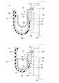
前記ブーツ210は中空筒状を成し、図6に示すように、両端部292,294がそれぞれ、ハウジング228のハウジング部234とハウジング266の上端部とに固定され、ゴムから成る周壁296と、周壁296内に埋設された複数本の張力部材としてのワイヤ297(図7および図10参照)とを含む。周壁296は、図6に示すように、軸方向の中間部において折り返された折返し部298を備え、ブーツ210は、その折返し部298の一方に位置する第1部300が、折返し部298の他方に位置する第2部302の内側へ進入させられ、折返し部298のブーツ210における軸方向位置の変化を伴って伸縮可能なダイヤフラム型ブーツとされている。 The
ワイヤ297は、図7に周壁296の一部を展開して示すように、複数本のワイヤ297の一部のものと残りのものとが、ブーツ210の軸線に対して互いに逆の巻き方向の螺旋に沿って配設されるとともに、それら一部のものと残りのものとが互いに交差するように配設され、互いに絡み合って網状を成す。これらワイヤ297は、前記実施例のブーツ24のワイヤ158と同様に、両端がそれぞれ金属製の嵌合片308(図6および図10参照)に固定され、それらワイヤ297および嵌合片308にゴムが加硫接着されてブーツ210が成形される。嵌合片308には、前記嵌合片168と同様に凹部310(図10参照)が設けられ、ワイヤ297の端部が嵌合されて、溶接,ろう付け等、適宜の固定手段によって固定されている。凹部310は、ワイヤ297の傾斜に沿った溝とすることが望ましい。 As shown in FIG. 7, a part of the
ワイヤ297および嵌合片308へのゴムの加硫接着は、例えば、型を用いて行われる。型内には、複数、例えば、4個を1組とする嵌合片308が2組、軸方向に隔たった2箇所にそれぞれ、一円周上に、隣接する嵌合片308の間の切除された部分に等しい隙間が生じるように配置されるとともに、螺旋状に配設され、各組の嵌合片308に両端が固定された複数本のワイヤ297が配設され、型内にゴムが注入されてワイヤ297および嵌合片308に加硫接着され、周壁296が形成される。それにより、複数本のワイヤ297が周壁296内に埋設され、第1部300,第2部302および折返し部298を有し、両端部292,294にそれぞれ嵌合片308が接着されたブーツ210が成形される。複数本のワイヤ297は、上記のように互いに巻き方向を逆にする螺旋に沿って配設されるとともに、交差させられており、周壁296のワイヤ297が他のワイヤ297と交差しない部分については、図8に示すように、複数本のワイヤ297が1列に並び、交差する部分については、図9に示すように、2列に並んだ状態で埋設される。 The rubber is vulcanized and bonded to the
ブーツ210の両端部292,294について、隣接する嵌合片308の間の部分がゴムにより埋められ、複数の嵌合片308が周壁296により弾性的に結合されることは、前記実施例と同じであるが、第1部300側の部分については、図10に示すように、ワイヤ297のブーツ210の内側の部分にゴムが接着されず、折返し部298においてはワイヤ297がブーツ210の内側面に表れた状態となるようにされる。 As for the both ends 292 and 294 of the
ブーツ210の両端部のうち、上側であって、第2部302側の端部292は、図6に示すように、止め輪314およびキャップ316を使用し、前記実施例のブーツ24の端部160,162と同様にして、ハウジング228のハウジング部234の外周部に液密に嵌合され、ワイヤ297がハウジング228に張力を伝達可能な状態で固定される。下側の端部294は、図10に示すように、止め輪318およびキャップ320を使用してハウジング266に取り付けられるが、キャップ320は伸長限度規定部322を備えたものとされ、伸長限度規定部材として機能する。キャップ320は、有底円筒状の嵌合部324を備え、伸長限度規定部322は、嵌合部324の開口端部全周から外側へ、底部側へ戻る向きに湾曲させられて横断面形状がU字形を成す。 Of the two ends of the
端部294は、拡径させられて4つの嵌合片308が、ハウジング266の上端部に設けられた円環状の溝326に嵌合され、その状態でキャップ320の嵌合部324が端部294に嵌合されるとともに、止め輪318が溝328に嵌め入れられる。端部294の外側面であって、ワイヤ297が内部に埋設された側の面はハウジング266に密着させられ、端部294は、周壁296がハウジング266に液密に嵌合された状態でハウジング266に固定される。キャップ320の伸長限度規定部322は、ブーツ210の内側に位置し、図10(a)に示すように、折返し部298と同じ方向へ湾曲させられ、折返し部298から離れた状態とされる。 The
ブーツ210の端部292,294がそれぞれ、ハウジング228,266に嵌合され、固定された状態では、図6に示すように、ブーツ210は連結部272およびシャフト250の外周を液密に囲み、ストッパ282はブーツ210の内側に位置し、サスペンションスプリング204はハウジング228,ブーツ210を外周側から囲む。ハウジング部236の下部およびシャフト250の下部はハウジング266内に収容され、シャフト250は、互いに内外に嵌合されたハウジング266とハウジング部236との中に位置するが、ハウジング266とハウジング部236との間はシールされておらず、泥水等が浸入するのに十分な隙間があり、シャフト250は見かけ上はハウジング部236およびハウジング266により覆われているが、実際には開放されているに等しい。そのため、ブーツ210が、両端部292,294がハウジング部234とハウジング266とに液密に嵌合され、固定されることにより、シャフト250および連結部272の外周はブーツ210により液密に囲まれ、シールされることとなる。このようにハウジング228,266に固定されたブーツ210は、軸方向においては連結部272と離れているが、半径方向においては連結部272より外周側に位置し、ハウジング228とハウジング266との間の空間を囲んで外部から遮断することにより、外部から連結部272への泥水等の浸入を防止し、連結部272はブーツ210により外周を液密に囲まれ、シールされることとなる。 In the state where the ends 292 and 294 of the
本サスペンション200において接近離間方向力発生装置206および受動的伸縮装置208は、運動変換機構218においてねじ軸220が回転させられ、ナット222が直線移動させられる点では異なるが、前記実施例のサスペンション10の接近離間方向力発生装置18および受動的伸縮装置20と同様に機能し、ばね上部材の振動や傾きが抑制され、ばね下部材の振動が減衰させられる。そして、路面の凹凸等により車輪がバウンドすれば、サスペンションスプリング204が圧縮されて車体側部材と車輪側部材とが接近させられ、その後、リバウンドによりサスペンションスプリング204が伸長し、車体側部材と車輪側部材とが離間させられる。ブーツ210は、バウンド時には、第1部300が第2部302に接近する向きに移動し、折返し部298がブーツ210の軸方向において上方へ移動して収縮し、ハウジング228,266の接近を許容する。バウンド時におけるハウジング228,266の接近限度は、ハウジング266がストッパ282に当接することにより規定される。 In the present suspension 200, the approach / separation direction force generator 206 and the passive expansion / contraction device 208 are different in that the
また、リバウンド時には、ブーツ210は、第1部300が第2部302から離れる向きに移動し、折返し部298がブーツ210の軸方向において下方へ移動して伸長し、ハウジング228,266の離間を許容する。周壁296内に埋設されたワイヤ297は折返し部298と共に移動するが、やがて移動限度に達し、ハウジング228,266の離間限度が規定される。ブーツ210がストッパとして機能するのである。ブーツ210の伸長時には、折返し部298は第1部300から第2部302へ向かう向きに移動し、折返し部298の移動限度は、図10(b)に示すように、キャップ320の伸長限度規定部322が折返し部298の内面に係合することにより規定され、ブーツ210の伸長限度が規定される。このブーツ210の伸長限度規定時に、折り返し部298には、ワイヤ297の嵌合片308からの延出し方向である下方とは逆の方向であって、上方への引張力が作用し、端部294をハウジング266から引き剥がそうとする力が作用するのであるが、その力の少なくとも一部は伸長限度規定部322により受けられて、ブーツ210の損傷が回避される。特に、本実施例においては、伸長限度規定部322が弾性変形を無視できる剛性を有しているため、端部294に作用する上向きの引張力の向きが伸長限度規定部322の案内によって変えられ、端部294の嵌合片308への結合端においては単純な下向きの引張力となり、その引張力は、嵌合片308と、それが嵌合される溝326の下側の溝側面との係合によりハウジング266に伝達される。また、折返し部298においては、ワイヤ297の内側部分にゴムが接着されていないため、伸長限度規定部322に係合するのはワイヤ297であり、ゴム製のブーツ210が金属製のワイヤ297と伸長限度規定部322との間に挟まれて損傷することが回避される。 Further, at the time of rebounding, the
なお、ベローズ型ブーツにおいて張力部材、例えば、ワイヤを、図7に示すように、複数本のうちの一部のものと残りのものとが、ブーツの軸線に対して互いに逆の巻き方向の螺旋に沿って配設してもよく、ダイヤフラム型ブーツにおいて張力部材、例えば、ワイヤを、図2に示すように、ブーツの軸線を含む各平面に沿ってそれぞれ配設してもよい。 In addition, as shown in FIG. 7, in the bellows type boot, a tension member, for example, a wire, a part of the plural pieces and the remaining one are spirals in the winding direction opposite to each other with respect to the boot axis. In the diaphragm type boot, a tension member such as a wire may be arranged along each plane including the axis of the boot as shown in FIG.
10:サスペンション 16:サスペンションユニット 18:サスペンションスプリング 20:接近離間方向力発生装置 22:受動的伸縮装置 24:ブーツ 30:回転電気機械 40:ハウジング 70:運動変換機構 72:ねじ軸 106:ハウジング 132:連結部 140:ストッパ 150:周壁 152:大径部 154:小径部 156:ベローズ部 158:ワイヤ 160,162:端部 200:サスペンション 202:サスペンションユニット 204:サスペンションスプリング 206:接近離間方向力発生装置 208:受動的伸縮装置 210:ブーツ 216:回転電気機械 218:運動変換機構 220:ねじ軸 222:ナット 228,266:ハウジング 272:連結部 292,294:端部 296:周壁 297:ワイヤ 298:折返し部 300:第1部 302:第2部 320:キャップ 322:伸長限度規定部 10: Suspension 16: Suspension unit 18: Suspension spring 20: Approaching / separating direction force generator 22: Passive telescopic device 24: Boot 30: Rotating electric machine 40: Housing 70: Motion conversion mechanism 72: Screw shaft 106: Housing 132: Connecting part 140: Stopper 150: Peripheral wall 152: Large diameter part 154: Small diameter part 156: Bellows part 158:
Claims (7)
Translated fromJapanese第2部材と、
それら第1部材と第2部材との間に延び、第1部材と第2部材との少なくとも一方に対して軸方向に相対移動可能な軸状部材と、
中空筒状をなし、両端部が前記第1部材と前記第2部材とにそれぞれ固定され、前記第1部材と前記第2部材との接近離間を許容しつつ前記軸状部材の外周を液密に囲むブーツと
を含む作動装置であって、前記ブーツが、
ゴムまたはその類似物から成り、両端部が前記第1部材と前記第2部材とに液密に固定された周壁と、
その周壁内に埋設され、両端部がそれぞれ前記第1部材と第2部材とに張力を伝達可能な状態で固定された複数本の張力部材と
を含み、前記第1部材と前記第2部材との離間限度を規定するストッパとして機能することを特徴とする作動装置。A first member;
A second member;
An axial member that extends between the first member and the second member and is movable relative to at least one of the first member and the second member in the axial direction;
It has a hollow cylindrical shape, both ends are fixed to the first member and the second member, respectively, and the outer periphery of the shaft-shaped member is liquid-tight while allowing the first member and the second member to approach and separate from each other. An actuating device comprising:
A peripheral wall made of rubber or the like and having both end portions liquid-tightly fixed to the first member and the second member;
A plurality of tension members that are embedded in the peripheral wall and that have both ends fixed to each of the first member and the second member in a state in which tension can be transmitted, and the first member, the second member, An actuating device that functions as a stopper that defines a separation limit of the actuator.
その接近離間方向力発生装置と直列に車体と車輪との間に配設され、第2ハウジングと、その第2ハウジングに対して軸方向に相対移動可能に設けられて前記出力部材と連結部によって連結された作動部材とを含み、外部から付与される力によって受動的に伸縮しつつその伸縮に対する抵抗力を発生させる受動的伸縮装置と、
中空筒状をなし、両端部が前記第1ハウジングと前記第2ハウジングとにそれぞれ固定され、前記第1ハウジングと前記第2ハウジングとの接近離間を許容しつつ前記連結部の外周を液密に囲むブーツと
を含むサスペンションであって、前記ブーツが、
ゴムまたはその類似物から成り、両端部が前記第1ハウジングと前記第2ハウジングとに液密に固定された周壁と、
その周壁内に埋設され、両端部がそれぞれ前記第1ハウジングと第2ハウジングとに張力を伝達可能な状態で固定された複数本の張力部材と
を含み、前記第1ハウジングと前記第2ハウジングとの離間限度を規定するストッパとして機能することを特徴とするサスペンション。A rotary electric machine, an output member, a motion conversion mechanism that converts rotation of the rotary electric machine into linear motion of the output member, and a first housing that houses at least the motion conversion mechanism therein, An approaching / separating direction force generator that generates an approaching / separating direction force that is a force in the approaching / separating direction between the vehicle body and the wheel,
It is arranged between the vehicle body and the wheel in series with the approaching / separating direction force generating device, is provided so as to be relatively movable in the axial direction with respect to the second housing, and is provided by the output member and the connecting portion. A passive expansion / contraction device including a connected operation member, and generating a resistance force against expansion / contraction while passively expanding / contracting by an externally applied force;
It has a hollow cylindrical shape, both ends are fixed to the first housing and the second housing, respectively, and the outer periphery of the connecting portion is liquid-tight while allowing the first housing and the second housing to approach and separate from each other. A suspension comprising surrounding boots, the boots comprising:
A peripheral wall made of rubber or the like and having both end portions liquid-tightly fixed to the first housing and the second housing;
A plurality of tension members embedded in the peripheral wall and having both ends fixed in a state capable of transmitting tension to the first housing and the second housing, respectively, the first housing, the second housing, Suspension characterized by functioning as a stopper that regulates the separation limit.
Priority Applications (1)
| Application Number | Priority Date | Filing Date | Title |
|---|---|---|---|
| JP2008033274AJP2009191944A (en) | 2008-02-14 | 2008-02-14 | Actuator and suspension |
Applications Claiming Priority (1)
| Application Number | Priority Date | Filing Date | Title |
|---|---|---|---|
| JP2008033274AJP2009191944A (en) | 2008-02-14 | 2008-02-14 | Actuator and suspension |
Publications (1)
| Publication Number | Publication Date |
|---|---|
| JP2009191944Atrue JP2009191944A (en) | 2009-08-27 |
Family
ID=41074150
Family Applications (1)
| Application Number | Title | Priority Date | Filing Date |
|---|---|---|---|
| JP2008033274AWithdrawnJP2009191944A (en) | 2008-02-14 | 2008-02-14 | Actuator and suspension |
Country Status (1)
| Country | Link |
|---|---|
| JP (1) | JP2009191944A (en) |
Cited By (6)
| Publication number | Priority date | Publication date | Assignee | Title |
|---|---|---|---|---|
| JP4756405B1 (en)* | 2010-09-15 | 2011-08-24 | 有限会社 加納 | Power generation device and its charging device |
| CN102777599A (en)* | 2012-03-26 | 2012-11-14 | 宁波天生密封件有限公司 | Connection sealing device for spallation neutron source target container and target vehicle |
| CN103133583A (en)* | 2011-11-23 | 2013-06-05 | 现代自动车株式会社 | Plastic composite spring for vehicle suspension and apparatus and method for manufacturing the same |
| US12043073B1 (en) | 2017-09-25 | 2024-07-23 | Apple Inc. | Multi-stage active suspension actuator |
| US12054028B1 (en) | 2019-06-03 | 2024-08-06 | Apple Inc. | Motion control systems |
| JP7554862B2 (en) | 2017-05-08 | 2024-09-20 | アップル インコーポレイテッド | Active Suspension System |
- 2008
- 2008-02-14JPJP2008033274Apatent/JP2009191944A/ennot_activeWithdrawn
Cited By (7)
| Publication number | Priority date | Publication date | Assignee | Title |
|---|---|---|---|---|
| JP4756405B1 (en)* | 2010-09-15 | 2011-08-24 | 有限会社 加納 | Power generation device and its charging device |
| CN103133583A (en)* | 2011-11-23 | 2013-06-05 | 现代自动车株式会社 | Plastic composite spring for vehicle suspension and apparatus and method for manufacturing the same |
| CN102777599A (en)* | 2012-03-26 | 2012-11-14 | 宁波天生密封件有限公司 | Connection sealing device for spallation neutron source target container and target vehicle |
| JP7554862B2 (en) | 2017-05-08 | 2024-09-20 | アップル インコーポレイテッド | Active Suspension System |
| US12115827B2 (en) | 2017-05-08 | 2024-10-15 | Apple Inc. | Motion control system |
| US12043073B1 (en) | 2017-09-25 | 2024-07-23 | Apple Inc. | Multi-stage active suspension actuator |
| US12054028B1 (en) | 2019-06-03 | 2024-08-06 | Apple Inc. | Motion control systems |
Similar Documents
| Publication | Publication Date | Title |
|---|---|---|
| JP2009191944A (en) | Actuator and suspension | |
| JP4500786B2 (en) | Shock absorber | |
| JP4667338B2 (en) | Shock absorber | |
| JP5260936B2 (en) | Electromagnetic shock absorber for vehicles | |
| JP4750617B2 (en) | Shock absorber | |
| JP6973696B1 (en) | Suspension device and its assembly method | |
| US8070169B2 (en) | Actuator for active roll control system | |
| JP2012167757A (en) | Electromagnetic shock absorber | |
| JP6084787B2 (en) | solenoid | |
| JP2009270670A (en) | Suspension device | |
| JP2008094226A (en) | Suspension device | |
| JP4942447B2 (en) | Shock absorber | |
| JP4868929B2 (en) | Shock absorber | |
| JP2008215588A (en) | Electromagnetic shock absorber | |
| WO2020158754A1 (en) | Electromagnetic shock absorber | |
| EP3290741B1 (en) | Hydraulic damper for a mount assembly | |
| JP2020125779A (en) | Electromagnetic shock absorber | |
| JP4708392B2 (en) | Electromagnetic shock absorber | |
| US20200292026A1 (en) | Mount for vehicle | |
| KR20240097956A (en) | Solenoid, damping force adjustment mechanism and damping force adjustable shock absorber | |
| JP2008247054A (en) | Vehicle suspension system | |
| JP2008045604A (en) | Suspension coupling device | |
| JP5263618B2 (en) | Electromagnetic suspension device | |
| JP4430489B2 (en) | Assembling method of damper for suspension device | |
| JP7570250B2 (en) | Damper |
Legal Events
| Date | Code | Title | Description |
|---|---|---|---|
| A300 | Withdrawal of application because of no request for examination | Free format text:JAPANESE INTERMEDIATE CODE: A300 Effective date:20110510 |