Movatterモバイル変換


[0]ホーム

URL:


JP2009189702A - Endoscopic treatment instrument device - Google Patents

Endoscopic treatment instrument device
Download PDF

Info

Publication number
JP2009189702A
JP2009189702AJP2008035893AJP2008035893AJP2009189702AJP 2009189702 AJP2009189702 AJP 2009189702AJP 2008035893 AJP2008035893 AJP 2008035893AJP 2008035893 AJP2008035893 AJP 2008035893AJP 2009189702 AJP2009189702 AJP 2009189702A
Authority
JP
Japan
Prior art keywords
treatment
bending
wire
endoscope
distal
Prior art date
Legal status (The legal status is an assumption and is not a legal conclusion. Google has not performed a legal analysis and makes no representation as to the accuracy of the status listed.)
Pending
Application number
JP2008035893A
Other languages
Japanese (ja)
Inventor
Hisamitsu Kobayashi
寿光 小林
Kunitoshi Ikeda
邦利 池田
Naoyuki Naito
直幸 内藤
Akiyoshi Matsubara
晃義 松原
Current Assignee (The listed assignees may be inaccurate. Google has not performed a legal analysis and makes no representation or warranty as to the accuracy of the list.)
Hoya Corp
National Cancer Center Japan
Original Assignee
Hoya Corp
National Cancer Center Japan
Priority date (The priority date is an assumption and is not a legal conclusion. Google has not performed a legal analysis and makes no representation as to the accuracy of the date listed.)
Filing date
Publication date
Application filed by Hoya Corp, National Cancer Center JapanfiledCriticalHoya Corp
Priority to JP2008035893ApriorityCriticalpatent/JP2009189702A/en
Publication of JP2009189702ApublicationCriticalpatent/JP2009189702A/en
Pendinglegal-statusCriticalCurrent

Links

Images

Landscapes

Abstract

Translated fromJapanese

【課題】可撓性を有する挿入部の先端に設けられた先端処置部の回転方向の位置調整を容易に行うことができ、操作性に優れた内視鏡用処置具装置を提供する。
【解決手段】挿入部先端の回転受け部に対して、先端処置部を挿入部の長手方向軸を中心として回転自在に支持させ、挿入部内に挿通され先端処置部に接続する処置部操作ワイヤに対して、挿入部の長手方向への進退移動と挿入部の長手方向軸を中心とする回転とを選択して与える操作手段を備えたことを特徴とする内視鏡用処置具装置。
【選択図】図4
An endoscope treatment instrument device that can easily adjust the position of a distal treatment section provided at the distal end of a flexible insertion section in the rotational direction and has excellent operability.
A treatment portion operating wire that is supported by a rotation receiving portion at a distal end of an insertion portion so as to be rotatable about a longitudinal axis of the insertion portion and is inserted into the insertion portion and connected to the distal treatment portion. On the other hand, an endoscopic treatment instrument device comprising operating means for selectively providing advancing / retreating movement of the insertion portion in the longitudinal direction and rotation about the longitudinal axis of the insertion portion.
[Selection] Figure 4

Description

Translated fromJapanese

本発明は、内視鏡の処置具挿通チャンネルに対して挿通される処置具装置に関する。  The present invention relates to a treatment instrument device that is inserted into a treatment instrument insertion channel of an endoscope.

内視鏡用の処置具は、可撓性を有する挿入部の先端に、把持鉗子や高周波スネアのような各種の処置を行う先端処置部が設けられており、内視鏡や付加的な案内具に形成された処置具挿通チャンネルに挿入部を挿通させ、この処置具挿通チャンネルから先端処置部を突出させて使用される。処置具の使用時にターゲットに対して先端処置部を位置合わせさせるための位置調整手段として、挿入部をその長手方向軸に対して湾曲させる湾曲操作機構が知られている。湾曲操作機構は、内視鏡本体に設けられたもの、特許文献1のように処置具の挿入部自体に設けられたもの、特許文献2のように処置具を挿通させる付加的な案内具に設けられたものなどが知られており、これらの湾曲操作機構による湾曲操作で先端処置部の向く方向を変化させることができる。
特許第3406703特開2004−8367号公報
Endoscopic treatment tools are provided with a distal treatment section for performing various treatments such as grasping forceps and a high-frequency snare at the distal end of a flexible insertion section. The treatment instrument insertion channel formed on the instrument is inserted into the insertion section, and the distal treatment section is projected from the treatment instrument insertion channel. A bending operation mechanism for bending an insertion portion with respect to its longitudinal axis is known as a position adjusting means for aligning the distal treatment portion with respect to a target when the treatment tool is used. The bending operation mechanism is provided in an endoscope main body, as provided in the insertion portion of the treatment tool itself as inPatent Document 1, or as an additional guide tool for inserting the treatment tool as inPatent Document 2. What is provided is known, and the direction in which the distal treatment section faces can be changed by a bending operation by these bending operation mechanisms.
Patent No. 3406703 JP 2004-8367 A

処置具においてはさらに、挿入部の長手方向軸を中心とした回転方向における先端処置部の角度位置についても設定を要する場合がある。特に、鉗子類は特定の動作平面内で開閉動作を行う構造であるため、湾曲操作機構によって挿入部の向きを変えた場合に、その操作平面が意図しない角度位置になる可能性がある。このような場合、先端処置部の回転方向位置の調整には、処置具装置全体を軸回りに回転させるなどしており、操作性の改善が望まれていた。  In the treatment instrument, it may be necessary to set the angular position of the distal treatment section in the rotation direction around the longitudinal axis of the insertion section. In particular, since the forceps have a structure that opens and closes within a specific operation plane, when the orientation of the insertion portion is changed by the bending operation mechanism, the operation plane may be at an unintended angular position. In such a case, in order to adjust the rotational position of the distal treatment section, the entire treatment instrument device is rotated about the axis, and improvement in operability has been desired.

また、先端処置部を操作するための操作部と、湾曲操作を行うための操作部の配置によっては、それぞれの操作部を操作しづらい場合があり、この点での操作性の改善も望まれている。  In addition, depending on the arrangement of the operation unit for operating the distal treatment unit and the operation unit for performing the bending operation, it may be difficult to operate each operation unit, and improvement in operability in this respect is also desired. ing.

本発明は以上の問題点に鑑みてなされたものであり、先端処置部の回転方向の位置調整を容易に行うことができ、操作性に優れた内視鏡用処置具装置を提供することを目的とする。本発明はまた、先端処置部に対する操作と湾曲操作のいずれにも優れた操作性を発揮する内視鏡用処置具装置を提供することを目的とする。  The present invention has been made in view of the above problems, and it is possible to easily adjust the position of the distal treatment section in the rotational direction, and to provide an endoscopic treatment instrument device excellent in operability. Objective. Another object of the present invention is to provide an endoscopic treatment instrument device that exhibits excellent operability for both the operation on the distal treatment section and the bending operation.

本発明は、可撓性を有する挿入部の先端に設けられ、挿入対象内での処置を行う先端処置部と、挿入部内に挿通されて先端処置部に接続する処置部操作ワイヤとを有する内視鏡用処置具において、挿入部先端の回転受け部に対して、先端処置部を挿入部の長手方向軸を中心として回転自在に支持させ、処置部操作ワイヤに対して、挿入部の長手方向への進退移動と挿入部の長手方向軸を中心とする回転とを選択して与え、この処置部操作ワイヤの回転によって先端処置部に回転動作を行わせる操作手段を備えたことを特徴としている。  The present invention includes an end treatment portion that is provided at the distal end of a flexible insertion portion and performs a treatment within an insertion target, and a treatment portion operation wire that is inserted into the insertion portion and connected to the distal treatment portion. In the endoscope treatment instrument, the distal treatment portion is supported rotatably about the longitudinal axis of the insertion portion with respect to the rotation receiving portion at the distal end of the insertion portion, and the longitudinal direction of the insertion portion with respect to the treatment portion operation wire It is characterized by comprising operating means for selecting and giving a forward / backward movement to and a rotation about the longitudinal axis of the insertion portion, and causing the distal treatment portion to perform a rotating operation by the rotation of the treatment portion operation wire. .

本発明では、挿入部先端に取り付ける先端処置部は様々なタイプとすることが可能であり、先端処置部の形態に応じて、回転受け部による支持構造を異ならせることができる。例えば、回転受け部には、挿入部の先端側に開口された円形孔を形成し、該円形孔の内周面の一部に内径サイズを大きくした環状溝を形成する一方、先端処置部側には、回転受け部の円形孔に相対回転自在に嵌る円筒部と、この円筒部の外面に支持され、回転受け部の環状溝に弾性的に係合して円形孔から先端処置部を抜け止めさせる弾性環状体とを設けた構成にすることができる。  In the present invention, the distal treatment section attached to the distal end of the insertion section can be of various types, and the support structure by the rotation receiving section can be varied according to the form of the distal treatment section. For example, a circular hole opened on the distal end side of the insertion portion is formed in the rotation receiving portion, and an annular groove having a larger inner diameter is formed on a part of the inner peripheral surface of the circular hole, while the distal treatment portion side Includes a cylindrical portion that is rotatably fitted in a circular hole of the rotation receiving portion, and is supported by an outer surface of the cylindrical portion, and elastically engages with an annular groove of the rotation receiving portion to exit the distal treatment portion from the circular hole. An elastic annular body to be stopped can be provided.

あるいは、回転受け部に挿入部の先端側に開口された円形孔を形成する一方、先端処置部が、回転受け部の円形孔内に挿入されて処置部操作ワイヤに接続するワイヤ接続端部と、このワイヤ接続端部から延設され円形孔から外方に突出し、この円形孔の開口縁部との接触によって開度が規制されるループワイヤ部とを有するように構成することも可能である。この場合、回転受け部の円形孔の開口縁部が、挿入部の先端側に進むにつれて徐々に開口径を大きくする部分円錐状のテーパ内周面となっていることが好ましい。  Or, while forming a circular hole opened on the distal end side of the insertion part in the rotation receiving part, the distal treatment part is inserted into the circular hole of the rotation receiving part and connected to the treatment part operation wire; It is also possible to have a loop wire portion that extends from the wire connection end portion, protrudes outward from the circular hole, and whose opening degree is regulated by contact with the opening edge of the circular hole. . In this case, it is preferable that the opening edge portion of the circular hole of the rotation receiving portion has a partially conical tapered inner peripheral surface in which the opening diameter gradually increases as it advances toward the distal end side of the insertion portion.

回転受け部は金属材料で形成することが好ましい。金属製にすることで、高周波電流を流すタイプの先端処置部を用いたとき、火花による焼け焦げを防ぐことができる。また、先端処置部が回転受け部に対して摺接するときの耐摩耗性も向上させることができる。安全性の観点から、金属製の回転受け部の外側は、絶縁性チューブで覆われることが望ましい。また、挿通部の長手方向に沿って配設されて処置部操作ワイヤを摺動自在に挿通させるワイヤガイド部材を有し、金属製の回転受け部の後部に、絶縁材からなりワイヤガイド部材の端部が接続固定されるワイヤガイド固定部材が固定されることが好ましい。この絶縁性を有するワイヤガイド固定部材を介在させることによって、回転受け部よりも後方に位置する挿入部内の他の金属部材へ電流が流れるのを防ぐことができる。  The rotation receiving part is preferably formed of a metal material. By using a metal, it is possible to prevent scorching due to sparks when a high-frequency current-type distal treatment section is used. Further, the wear resistance when the distal treatment portion is in sliding contact with the rotation receiving portion can be improved. From the viewpoint of safety, it is desirable that the outside of the metal rotation receiving portion is covered with an insulating tube. In addition, a wire guide member that is disposed along the longitudinal direction of the insertion portion and allows the treatment portion operation wire to be slidably inserted therethrough is formed of an insulating material at the rear portion of the metal rotation receiving portion. It is preferable that the wire guide fixing member whose end is connected and fixed is fixed. By interposing this wire guide fixing member having an insulating property, it is possible to prevent current from flowing to other metal members in the insertion portion located behind the rotation receiving portion.

回転受け部とワイヤガイドの固定手段は任意に選択できるが、例えば、回転受け部とワイヤガイドの一方と他方に、挿入部の長手方向軸を中心とする環状をなし互いに嵌合する環状凹部と環状凸部を形成し、この環状凹部と環状凸部の対向周面上に形成した係合爪と爪係合凹部の係合によって回転受け部とワイヤガイドを一体化させるとよい。  The fixing means for the rotation receiving portion and the wire guide can be arbitrarily selected. For example, one of the rotation receiving portion and the wire guide is formed with an annular recess centered on the longitudinal axis of the insertion portion and fitted to each other. An annular protrusion is formed, and the rotation receiving portion and the wire guide may be integrated by engagement of an engagement claw and a claw engagement recess formed on the circumferential surface of the annular recess and the annular protrusion.

本発明の内視鏡用処置具では、挿入部の基端部が接続する保持部から該挿入部とは反対方向に突出し、この突出方向への進退操作と、突出方向を向く軸線を中心とした回転操作とが可能に支持された操作ハンドルを設け、この操作ハンドルに処置部操作ワイヤが接続されるように構成するとよい。  In the endoscope treatment tool of the present invention, the proximal end portion of the insertion portion protrudes in a direction opposite to the insertion portion, and the advancement / retraction operation in the protrusion direction and the axis line facing the protrusion direction are the center. It is preferable that an operation handle supported so as to be able to perform the rotation operation is provided, and a treatment portion operation wire is connected to the operation handle.

より具体的には、保持部には、絶縁体からなる保持部外観部材と、この保持部外観部材を貫通して支持され、保持部の内側でワイヤガイド部材の端部を接続固定させ、保持部の外側に操作ハンドルを接続させる連結口金を支持した中継環とを備え、処置部操作ワイヤは、この中継環を貫通して保持部外方に延出されて操作ハンドルに接続されるように構成するとよい。  More specifically, the holding portion is supported by penetrating the holding portion appearance member made of an insulator and the holding portion appearance member, and the end portion of the wire guide member is connected and fixed inside the holding portion. A relay ring that supports a coupling base for connecting the operation handle to the outside of the unit, and the treatment unit operation wire extends through the relay ring to the outside of the holding unit and is connected to the operation handle. Configure.

本発明の内視鏡用処置具ではさらに、挿入部の先端付近の一部を、該挿入部の長手方向軸に対して湾曲動作が可能な湾曲部とし、保持部から、挿入部と操作ハンドルを結ぶ保持部軸線と略直交する方向に向けて、湾曲部を湾曲操作するための湾曲操作グリップを突設させることが好ましい。この保持部からの湾曲操作グリップの突設方向は、湾曲部の複数の湾曲方向のいずれかと略一致していると、なお良い。  In the endoscope treatment tool of the present invention, a portion near the distal end of the insertion portion is a bending portion capable of bending with respect to the longitudinal axis of the insertion portion, and the insertion portion and the operation handle are moved from the holding portion. It is preferable to project a bending operation grip for bending the bending portion in a direction substantially orthogonal to the holding portion axis connecting the two. It is more preferable that the projecting direction of the bending operation grip from the holding portion substantially coincides with one of the plurality of bending directions of the bending portion.

また、保持部に対して湾曲操作グリップを、その突出方向の軸線を中心とする回転方向に角度調整可能に支持する角度調整支持機構を備えると、さらに操作性を向上させることができる。  Further, the operability can be further improved by providing an angle adjustment support mechanism that supports the bending operation grip with respect to the holding portion so that the angle of the bending operation grip can be adjusted in the rotation direction around the axis of the protruding direction.

湾曲操作グリップには、同軸で回動可能な2つの湾曲操作部材を備え、一方の湾曲操作部材と他方の湾曲操作部材を回動操作したときに、上記湾曲部が互いに略直交する方向へ湾曲動作されるように構成するとよい。  The bending operation grip is provided with two bending operation members that can rotate coaxially, and when the one bending operation member and the other bending operation member are rotated, the bending portions are bent in directions substantially orthogonal to each other. It may be configured to be operated.

以上の本発明の内視鏡用処置具装置によれば、操作手段の手元操作によって先端処置部の回転方向の位置調整を容易に行うことが可能で、操作性に優れた内視鏡用処置具装置が得られる。また、以上のような構造の操作ハンドルと湾曲操作グリップによると、先端処置部に対する操作と湾曲操作の両方の操作性を高めることができる。  According to the endoscopic treatment instrument device of the present invention described above, it is possible to easily adjust the position of the distal treatment section in the rotation direction by hand operation of the operating means, and the endoscopic treatment having excellent operability. A device is obtained. Further, according to the operation handle and the bending operation grip having the above-described structure, the operability of both the operation and the bending operation on the distal treatment section can be improved.

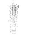
図1は、本発明を適用した内視鏡用処置具装置10の全体構造を示している。内視鏡用処置具装置10は、内視鏡の処置具挿通チャンネル、もしくは内視鏡に対して付加的に取り付けられる案内具の処置具挿通チャンネルに対して挿入可能な挿入部11を有し、この挿入部11の基部が筒状の保持部12に接続している。挿入部11は、先端処置部13、湾曲部14及び可撓管部15からなっており、保持部12における挿入部11と反対側の後端部には、先端処置部13を操作するための処置部操作ハンドル16が設けられている。また、保持部12における中間部には、挿入部11と処置部操作ハンドル16を結ぶ保持部12の軸線方向に対して略直交する方向に向けて湾曲操作グリップ17が突設されている。以降の説明において、挿入部11における軸線方向とは、その長手方向を意味し、図1のように挿入部11を直線状に伸ばした場合には、挿入部11の軸線と保持部12の軸線がほぼ一致する。  FIG. 1 shows the overall structure of an endoscopetreatment tool device 10 to which the present invention is applied. The endoscopetreatment tool device 10 includes aninsertion portion 11 that can be inserted into a treatment tool insertion channel of an endoscope or a treatment tool insertion channel of a guide tool that is additionally attached to the endoscope. The base portion of theinsertion portion 11 is connected to thecylindrical holding portion 12. Theinsertion portion 11 includes adistal treatment portion 13, abending portion 14, and aflexible tube portion 15. A rear end portion of theholding portion 12 opposite to theinsertion portion 11 is used for operating thedistal treatment portion 13. A treatmentsection operation handle 16 is provided. In addition, abending operation grip 17 projects from the intermediate portion of theholding portion 12 in a direction substantially orthogonal to the axial direction of theholding portion 12 that connects theinsertion portion 11 and the treatmentportion operation handle 16. In the following description, the axial direction of theinsertion portion 11 means the longitudinal direction, and when theinsertion portion 11 is linearly extended as shown in FIG. 1, the axis of theinsertion portion 11 and the axis of theholding portion 12. Is almost the same.

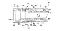
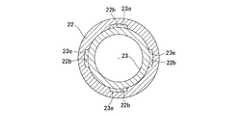
図4及び図5は、先端処置部13付近を拡大して一部を断面として示した図である。湾曲部14は、網状管20の外側を絶縁体からなる被覆チューブ21で覆った構造をなし、その先端部に先端硬性部材が設けられている。先端硬性部材は、合成樹脂製のワイヤガイド固定部材22と、金属製の枠受け環(回転受け部)23からなっている。ワイヤガイド固定部材22の前端部には環状凹部22aが形成され、この環状凹部22aに対して枠受け環23に形成した環状凸部23aが挿入され、環状凸部23aと環状凹部22aの間が接着で固定されて一体化された先端硬性部材となっている。枠受け環23の外側は絶縁チューブ19で覆われている。絶縁チューブ19は熱収縮性チューブからなり、枠受け環23に加えて湾曲部14側の被覆チューブ21の先端付近も覆っている。  4 and 5 are enlarged views of the vicinity of thedistal treatment section 13 and a part thereof as a cross section. Thebending portion 14 has a structure in which the outer side of themesh tube 20 is covered with acovering tube 21 made of an insulator, and a distal end rigid member is provided at the distal end portion thereof. The distal end rigid member includes a synthetic resin wireguide fixing member 22 and a metal frame receiving ring (rotation receiving portion) 23. Anannular recess 22a is formed at the front end of the wireguide fixing member 22, and anannular projection 23a formed on theframe receiving ring 23 is inserted into theannular recess 22a, and the gap between theannular projection 23a and theannular recess 22a is inserted. It is an end hard member that is fixed by bonding and integrated. The outside of theframe receiving ring 23 is covered with aninsulating tube 19. Theinsulating tube 19 is made of a heat-shrinkable tube, and covers the vicinity of the tip of thecovering tube 21 on thecurved portion 14 side in addition to theframe receiving ring 23.

枠受け環23は、環状凸部23aより前方に、該環状凸部23aよりも内径サイズを大きくした円形の枠支持孔(円形孔)23bが形成され、枠支持孔23bの軸線方向の中間位置に、枠支持孔23bよりも内径サイズの大きい環状のリング嵌合溝(環状溝)23cが形成されている。枠支持孔23bの開口縁部は、挿入部11の先端側に進むにつれて徐々に開口径を大きくする部分円錐状のテーパ内周面23dとなっている。枠支持孔23bに対して、先端処置部13を構成する回転自在枠24の後端円筒部(円筒部)24aが相対回転可能に挿入される。後端円筒部24aの外周面には、半径方向に弾性的に拡縮変形可能なスナップリング(弾性環状体)25が支持されており、後端円筒部24aを枠支持孔23bに挿入すると、スナップリング25が内径方向に縮径された状態でリング嵌合溝23cに弾性的に嵌合して、枠受け環23に対して回転自在枠24が軸線方向の移動が規制された状態で抜け止め保持される。このスナップリング25を介した保持状態で、回転自在枠24は、枠受け環23に対して軸線を中心とする回転動作が許容される。  Theframe receiving ring 23 is formed with a circular frame support hole (circular hole) 23b having a larger inner diameter than theannular convex portion 23a in front of theannular convex portion 23a, and an intermediate position in the axial direction of theframe support hole 23b. In addition, an annular ring fitting groove (annular groove) 23c having an inner diameter larger than that of theframe support hole 23b is formed. The opening edge portion of theframe support hole 23b is a partially conical tapered innerperipheral surface 23d that gradually increases in opening diameter as it advances toward the distal end side of theinsertion portion 11. A rear end cylindrical portion (cylindrical portion) 24a that constitutes thedistal treatment section 13 is inserted into theframe support hole 23b so as to be relatively rotatable. A snap ring (elastic annular body) 25 that is elastically expandable and contractible in the radial direction is supported on the outer peripheral surface of the rear endcylindrical portion 24a. When the rear endcylindrical portion 24a is inserted into theframe support hole 23b, the snap ring is snapped. Thering 25 is elastically fitted into thering fitting groove 23c with the diameter reduced in the inner diameter direction, and therotatable frame 24 is prevented from coming off in a state where movement in the axial direction is restricted with respect to theframe receiving ring 23. Retained. In the holding state via thesnap ring 25, therotatable frame 24 is allowed to rotate about the axis with respect to theframe receiving ring 23.

回転自在枠24を枠受け環23に取り付けた状態で、ワイヤガイド固定部材22、枠受け環23及び回転自在枠24の内部には、略面一な円筒状内周面の進退ガイド孔26が形成される。この進退ガイド孔26に対してスライド部材27が摺動自在に支持されている。スライド部材27には、処置具操作ワイヤ28のワイヤ先端部28aが接続されている。スライド部材27に対してワイヤ先端部28aは、ロウ付け、ハンダ付け、かしめ等の手段によって固定されている。処置具操作ワイヤ28は、先端部がワイヤガイド固定部材22に固定されたガイドチューブ(ワイヤガイド部材)29内に、挿入部11の長手方向への進退と該長手方向の軸線を中心とする相対回転のいずれも可能に挿通されている。ガイドチューブ29は、四フッ化エチレン樹脂(PTFE)、ポリエチレン、ポリアミド、ポリウレタンなどの絶縁性及び可撓性を有する材質からなり、挿入部11内を貫通して保持部12の後端部付近まで延設されている。ガイドチューブ29内に挿入された処置具操作ワイヤ28の後端は補強パイプ44に固定され、補強パイプ44が保持部12の後端部から後方に突出して、固定用端部材46を介して処置部操作ハンドル16に接続している。この処置部操作ハンドル16と固定用端部材46の接続構造については後述する。そして、処置部操作ハンドル16を介して処置具操作ワイヤ28、補強パイプ44及び固定用端部材46を挿入部11の長手方向に押し引きすることで、進退ガイド孔26内でスライド部材27を軸線方向に進退移動させることができる。  With therotatable frame 24 attached to theframe receiving ring 23, the wireguide fixing member 22, theframe receiving ring 23, and therotatable frame 24 have a substantially flush inner cylindrical advance /retreat guide hole 26. It is formed. Aslide member 27 is slidably supported by the advance /retreat guide hole 26. Theslide member 27 is connected to a wiredistal end portion 28 a of the treatmentinstrument operation wire 28. Thewire tip 28a is fixed to theslide member 27 by means such as brazing, soldering, or caulking. The treatmentinstrument operation wire 28 is moved forward and backward in the longitudinal direction of theinsertion portion 11 and relative to the longitudinal axis in the guide tube (wire guide member) 29 having a distal end portion fixed to the wireguide fixing member 22. Any rotation is possible. Theguide tube 29 is made of an insulating and flexible material such as tetrafluoroethylene resin (PTFE), polyethylene, polyamide, polyurethane, and penetrates theinsertion portion 11 to the vicinity of the rear end portion of the holdingportion 12. It is extended. The rear end of the treatmentinstrument operating wire 28 inserted into theguide tube 29 is fixed to the reinforcingpipe 44, and the reinforcingpipe 44 protrudes rearward from the rear end of the holdingportion 12 and is treated via the fixingend member 46. Connected to theoperation handle 16. A connection structure between the treatment portion operation handle 16 and the fixingend member 46 will be described later. Then, by pushing and pulling the treatmentinstrument operation wire 28, the reinforcingpipe 44, and the fixingend member 46 in the longitudinal direction of theinsertion portion 11 through the treatment portion operation handle 16, theslide member 27 is axially moved in the advance /retreat guide hole 26. Can move forward and backward in the direction.

回転自在枠24より先の先端処置部13は、スナップリング25とリング嵌合溝23cによる弾性係合力を超える大きさで引き抜くことにより、取り外しが可能であり、用途に応じた様々な処置具に交換することができる。図1から図6に表されている先端処置部13は把持鉗子であり、その概略構造は次の通りである。回転自在枠24は、後端円筒部24aから前方に向けて、互いに対向する一対のベース板部24b、24cを延設させている。図5に示すように、スライド部材27の先端部はベース板部24b、24cの間に挿入されており、このスライド部材27の先端部を挟むようにして、リンク支持軸30を介して一対のリンク31、32の基端部がそれぞれ回動自在に支持されている。リンク支持軸30は回転自在枠24に対して固定されておらず、スライド部材27の進退方向に位置を変化させることができる。各リンク31、32の先端部にはそれぞれ、連結軸33、34を介して一対の鉗子部材35、36の基端部が回動自在に支持されている。鉗子部材35と鉗子部材36はさらに、連結軸33、34による連結位置よりも若干先端寄りに位置する軸着部37、38で、回転自在枠24(ベース板部24b、24c)に固定した開閉回動軸39によって相対回動自在に支持されている。回転自在枠24においてベース板部24b、24cの両側部は開放されており、図4に示すようにリンク31やリンク32を側方へ突出させることが可能となっている。  Thedistal treatment section 13 ahead of therotatable frame 24 can be removed by pulling out with a size exceeding the elastic engagement force by thesnap ring 25 and thering fitting groove 23c. Can be exchanged. Thedistal treatment section 13 shown in FIGS. 1 to 6 is a grasping forceps, and its schematic structure is as follows. Therotatable frame 24 has a pair ofbase plate portions 24b and 24c facing each other extending from the rear endcylindrical portion 24a to the front. As shown in FIG. 5, the distal end portion of theslide member 27 is inserted between thebase plate portions 24 b and 24 c, and a pair oflinks 31 are interposed via thelink support shaft 30 so as to sandwich the distal end portion of theslide member 27. , 32 are rotatably supported. Thelink support shaft 30 is not fixed with respect to therotatable frame 24 and can change its position in the forward / backward direction of theslide member 27. The proximal end portions of the pair offorceps members 35 and 36 are rotatably supported at the distal end portions of thelinks 31 and 32 via connectingshafts 33 and 34, respectively. Theforceps member 35 and theforceps member 36 are further opened and closed fixed to the rotatable frame 24 (base plate portions 24b and 24c) byshaft attachment portions 37 and 38 located slightly closer to the tip than the connection position by theconnection shafts 33 and 34. Therotary shaft 39 is supported so as to be relatively rotatable. In therotatable frame 24, both side portions of thebase plate portions 24b and 24c are opened, and thelink 31 and thelink 32 can be protruded laterally as shown in FIG.

一対の鉗子部材35、36はそれぞれ、軸着部37、38から先端側に向けて直線状の腕部35a、36aを延出させており、この腕部35a、36aの先端に、互いに噛合可能な鋸歯状の対向面が形成された噛合部35b、36bを有している。  The pair offorceps members 35 and 36 havelinear arm portions 35a and 36a extending from theshaft attachment portions 37 and 38 toward the distal end, respectively, and can be engaged with the distal ends of thearm portions 35a and 36a. It has the meshingparts 35b and 36b in which the serrated opposing surface was formed.

以上の先端処置部13(把持鉗子)は、処置具操作ワイヤ28を介して図4及び図5の右手方向にスライド部材27を移動させると、リンク支持軸30と開閉回動軸39の軸位置間隔が増大し、該リンク支持軸30を回動中心として、連結軸33と連結軸34を互いに接近させるようにリンク31、32が回動する。すると、連結軸33と連結軸34の位置変化に応じて、一対の鉗子部材35、36は、それぞれの先端の噛合部35b、36bを接近させる閉じ方向に開閉回動軸39を中心として相対回動する。図4は、スライド部材27が図中右手方向に最大に移動されて、鉗子部材35、36が閉じられた状態を示している。このとき、噛合部35b、36bの対向面が噛み合っている。一方、処置具操作ワイヤ28を介して図4及び図5の左手方向にスライド部材27を移動させると、リンク支持軸30が開閉回動軸39に接近し、該リンク支持軸30を回動中心として、連結軸33と連結軸34を互いに離間させるようにリンク31、32が回動する。すると、連結軸33と連結軸34の位置変化に応じて、一対の鉗子部材35、36は、それぞれの先端の噛合部35b、36bを離間させる開き方向に開閉回動軸39を中心として相対回動する。  When theslide member 27 is moved in the right-hand direction in FIGS. 4 and 5 through the treatmentinstrument operation wire 28, the distal treatment section 13 (gripping forceps) described above moves the axial positions of thelink support shaft 30 and the opening /closing rotation shaft 39. The interval increases, and thelinks 31 and 32 rotate so that the connecting shaft 33 and the connectingshaft 34 approach each other with thelink support shaft 30 as the rotation center. Then, according to the position change of the connecting shaft 33 and the connectingshaft 34, the pair offorceps members 35 and 36 rotate relative to each other with the opening andclosing rotation shaft 39 as a center in the closing direction in which the engagingportions 35b and 36b at the tips of the pair offorceps members 35 and 36 approach each other. Move. FIG. 4 shows a state where theslide member 27 is moved to the maximum in the right hand direction in the drawing and theforceps members 35 and 36 are closed. At this time, the opposing surfaces of the meshingportions 35b and 36b are meshed with each other. On the other hand, when theslide member 27 is moved in the left-hand direction of FIGS. 4 and 5 via the treatmentinstrument operation wire 28, thelink support shaft 30 approaches the opening /closing rotation shaft 39, and thelink support shaft 30 is set to the rotation center. As a result, thelinks 31 and 32 rotate so as to separate the connecting shaft 33 and the connectingshaft 34 from each other. Then, according to the change in the position of the connecting shaft 33 and the connectingshaft 34, the pair offorceps members 35, 36 rotate relative to each other about the opening /closing rotation shaft 39 in the opening direction that separates theengagement portions 35b, 36b at the distal ends. Move.

図7及び図8に示すように、保持部12の外観を構成する保持部本体(保持部外観部材)77の後端部には貫通孔が形成され、この貫通孔内に、固定ナット40を介してチューブ固定環(中継環)41が取り付けられている。チューブ固定環41は金属製の部材である。図9に示すように、保持部本体77に対するチューブ固定環41の嵌合部は角筒状をなしていて、相対回転が規制されている。処置具操作ワイヤ28が挿通されるガイドチューブ29の後端部は、チューブ固定環41から保持部12の内方に突設された筒状ニップル部41a(図8)に被着され、固定用コイル45によって固定されている。ガイドチューブ29は、挿入部11に対応して変形可能な可撓性を有しているが、その先端部がワイヤガイド固定部材22に固定され、かつ後端部がチューブ固定環41に対して固定されているため、挿入部11や保持部12内において軸線方向への移動や軸線を中心とした回転は規制されている。また、チューブ固定環41は保持部12の後端面からの突出部41bを有し、この突出部に対して固定ネジ42によって連結口金43が固定されている。  As shown in FIGS. 7 and 8, a through hole is formed in the rear end portion of the holding portion main body (holding portion appearance member) 77 constituting the appearance of the holdingportion 12, and a fixingnut 40 is placed in the through hole. A tube fixing ring (relay ring) 41 is attached through the via. Thetube fixing ring 41 is a metal member. As shown in FIG. 9, the fitting portion of thetube fixing ring 41 with respect to the holding portionmain body 77 has a rectangular tube shape, and relative rotation is restricted. A rear end portion of theguide tube 29 through which the treatmentinstrument operation wire 28 is inserted is attached to acylindrical nipple portion 41a (FIG. 8) projecting inward of the holdingportion 12 from thetube fixing ring 41, and is fixed. It is fixed by acoil 45. Theguide tube 29 has flexibility that can be deformed corresponding to theinsertion portion 11, but its distal end portion is fixed to the wireguide fixing member 22 and its rear end portion is relative to thetube fixing ring 41. Since it is fixed, movement in the axial direction and rotation around the axial line are restricted in theinsertion portion 11 and the holdingportion 12. Further, thetube fixing ring 41 has a protrudingportion 41 b from the rear end surface of the holdingportion 12, and aconnection base 43 is fixed to the protruding portion by a fixingscrew 42.

処置具操作ワイヤ28の後端に固定された補強パイプ44は、その前端が保持部12内に突出してガイドチューブ29内に挿入され、チューブ固定環41と連結口金43の内部に挿通されて、該連結口金43の後方に突出している。補強パイプ44の後端には固定用端部材46が取り付けられている。固定用端部材46の軸方向中間部は、その前後に比べて外径サイズの小さい小径部46aとなっている。処置具操作ワイヤ28と補強パイプ44、補強パイプ44と固定用端部材46はそれぞれ、ロウ付け、ハンダ付け、かしめ等の手法によって固定されており、固定用端部材46から処置具操作ワイヤ28までの全体が導電性を有している。  The reinforcingpipe 44 fixed to the rear end of the treatmentinstrument operation wire 28 has a front end protruding into the holdingportion 12 and inserted into theguide tube 29, and is inserted into thetube fixing ring 41 and theconnection base 43. The connectingcap 43 protrudes rearward. A fixingend member 46 is attached to the rear end of the reinforcingpipe 44. The axially intermediate portion of the fixingend member 46 is a small-diameter portion 46a having a smaller outer diameter than before and after that. The treatmentinstrument operation wire 28 and the reinforcingpipe 44, and thereinforcement pipe 44 and the fixingend member 46 are fixed by a technique such as brazing, soldering, and caulking, respectively, from the fixingend member 46 to the treatmentinstrument operation wire 28. The whole has conductivity.

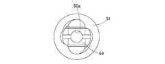
図10から図13に示すように、処置部操作ハンドル16の先端部分には、軸線方向に沿って複数のスリットが形成された筒状の口金連結体50が設けられ、口金連結体50の外側を囲んで締結環51が回転可能に支持されている。図11及び図13に示すように、口金連結体50の外形は2つの小判形を組み合わせた態様の断面形状をなしており、締結環51は、これに対応するように2つの小判形を組み合わせた内面形状を有している。口金連結体50の中央には、スリットの拡縮により形状を変化させる中央開口50aが形成されている。これにより、軸線を中心とした締結環51の回転動作に応じて、口金連結体50のスリットが開かれて中央開口50aが拡径される着脱可能状態と、スリットが狭められて中央開口50aが縮径される締結状態とにさせることができる。締結状態では、口金連結体50は、連結口金43に対して軸方向の動きは規制されるが、回転は自在である。図10と図11は着脱可能状態を示し、図12と図13は締結状態を示している。そして、図7のように連結口金43を口金連結体50の中央開口50aに差し込んだ状態で締結環51を回転させて締結状態にすることで、処置部操作ハンドル16を保持部12に取り付けることができる。逆に、口金連結体50の中央開口50aに連結口金43が差し込まれた状態で締結環51を着脱可能位置に回転させることで、保持部12から処置部操作ハンドル16を取り外すことができる。  As shown in FIGS. 10 to 13, a distal end portion of the treatment section operation handle 16 is provided with acylindrical base connector 50 in which a plurality of slits are formed along the axial direction. Thefastening ring 51 is supported so as to be rotatable. As shown in FIGS. 11 and 13, the outer shape of thebase connector 50 has a cross-sectional shape in which two oval shapes are combined, and thefastening ring 51 combines two oval shapes so as to correspond thereto. It has an inner surface shape. In the center of thebase connector 50, acentral opening 50a is formed whose shape is changed by expansion and contraction of the slit. Thereby, according to the rotation operation of thefastening ring 51 around the axis, the detachable state in which the slit of thebase coupling body 50 is opened and thecentral opening 50a is enlarged, and the slit is narrowed and thecentral opening 50a is opened. It can be made the fastening state diameter-reduced. In the fastened state, thebase connection body 50 is restricted from moving in the axial direction with respect to theconnection base 43 but can freely rotate. 10 and 11 show the detachable state, and FIGS. 12 and 13 show the fastened state. And the treatment part operation handle 16 is attached to the holding |maintenance part 12 by rotating thefastening ring 51 in the state which inserted the connection nozzle | cap | die 43 in the center opening 50a of the nozzle | cap | diecoupling body 50 like FIG. Can do. Conversely, the treatment portion operation handle 16 can be removed from the holdingportion 12 by rotating thefastening ring 51 to the attachable / detachable position in a state where theconnection cap 43 is inserted into thecentral opening 50 a of thecap connection body 50.

口金連結体50の後端には処置部操作ハンドル16の本体部を構成する筒体52が固定されている。筒体52内には軸線方向に向けて長溝52a(図1ないし図3)が形成されていて、この長溝52a内に、ワイヤ連結部材53の一部が軸線方向に摺動自在に嵌まっている。また、筒体52の外側には、フランジ状の指掛け部54aを外面に有するスライダ54が支持されている。ワイヤ連結部材53からは、筒体52の軸線と直交する径方向に向けて側方端子55が突出されていて、この側方端子55の基部と係合することによって、スライダ54は、ワイヤ連結部材53と一体化されている。すなわち、スライダ54とワイヤ連結部材53は、筒体52の軸線方向と該軸線を中心とした回転方向のいずれにも一体的に動作する。筒体52の前端部に設けた口金連結体50は連結口金43に対して回転可能に接続されるため、該口金連結体50と連結口金43の接続状態では、処置部操作ハンドル16の全体が保持部12(連結口金43)に対して軸回りに回転可能となる。また、筒体52は、ワイヤ連結部材53及びスライダ54と回転方向には一体化されているが、その軸線方向には、長溝52aによってワイヤ連結部材53及びスライダ54の相対移動を許容している。筒体52の末端部には指通しリング56が設けられている。  Acylindrical body 52 constituting the main body of the treatment section operation handle 16 is fixed to the rear end of thebase connector 50. Along groove 52a (FIGS. 1 to 3) is formed in thecylindrical body 52 in the axial direction, and a part of thewire connecting member 53 is slidably fitted in thelong groove 52a in the axial direction. Yes. Further, aslider 54 having a flange-like finger-hangingportion 54 a on the outer surface is supported on the outer side of thecylindrical body 52. Aside terminal 55 protrudes from thewire connecting member 53 in a radial direction orthogonal to the axis of thecylindrical body 52, and theslider 54 is connected to thewire connecting member 53 by engaging with the base of theside terminal 55. It is integrated with themember 53. In other words, theslider 54 and thewire connecting member 53 operate integrally in both the axial direction of thecylindrical body 52 and the rotational direction around the axial line. Since thebase connection body 50 provided at the front end of thecylindrical body 52 is rotatably connected to theconnection base 43, the entire treatment section operation handle 16 is in a connected state between thebase connection body 50 and theconnection base 43. It becomes possible to rotate around the axis with respect to the holding portion 12 (connection base 43). In addition, thecylindrical body 52 is integrated with thewire connecting member 53 and theslider 54 in the rotational direction, but relative movement of thewire connecting member 53 and theslider 54 is allowed in the axial direction by along groove 52a. . Afinger ring 56 is provided at the end of thecylindrical body 52.

ワイヤ連結部材53には、固定用端部材46を挿入させるワイヤ端部支持孔53aが形成されている。側方端子55は、高周波スネアなどの電気処置具を使用する際に外部の電源部から高周波電流が入力される端子であり、ワイヤ連結部材53とはネジ結合されており、操作環55bを正逆に回転させることにより、側方端子55の内径側端部55aがワイヤ端部支持孔53a内への突出量を変化させる。組立時には、ワイヤ端部支持孔53a内への内径側端部55aの突出量を大きくさせ、固定部端部材46の小径部46aに当接させながら、該固定部端部材46をワイヤ端部支持孔53aの側面に押し当てる。このとき、側方端子55の内径側端部55aは、固定用端部材46の小径部46aに当接した状態になっているため、固定用端部材46がワイヤ端部支持孔53aに対して抜け止めされる。  Thewire connecting member 53 is formed with a wireend support hole 53a into which the fixingend member 46 is inserted. Theside terminal 55 is a terminal to which a high-frequency current is input from an external power supply unit when using an electric treatment instrument such as a high-frequency snare, and is screw-coupled to thewire connecting member 53 so that theoperation ring 55b is properly connected. By rotating in reverse, the inner diameterside end portion 55a of theside terminal 55 changes the amount of protrusion into the wire endportion support hole 53a. At the time of assembly, the protruding portion of the inner diameterside end portion 55a into the wire endportion supporting hole 53a is increased, and the fixedportion end member 46 is supported on the wire end portion while contacting thesmall diameter portion 46a of the fixedportion end member 46. Press against the side of thehole 53a. At this time, since the inner diameterside end portion 55a of theside terminal 55 is in contact with thesmall diameter portion 46a of the fixingend member 46, the fixingend member 46 is in contact with the wire endportion support hole 53a. It is prevented from coming off.

前述の通り、ガイドチューブ29は、その一端部と他端部がワイヤガイド固定部材22とチューブ固定環41に固定されたガイド部材であり、このガイドチューブ29の内部に処置具操作ワイヤ28が挿通されている。ガイドチューブ29に対して処置具操作ワイヤ28は、その長手方向に摺動自在で、かつ内部での相対回転も自在に挿通されている。そのため、図2に矢印S1で示すように、処置部操作ハンドル16において筒体52に対してスライダ54を軸線方向に進退操作することにより、ワイヤ連結部材53を介して処置具操作ワイヤ28が、ガイドチューブ29内でその長手方向に進退される。このとき、補強パイプ44も処置具操作ワイヤ28と共に進退される。この処置具操作ワイヤ28の進退操作が先端処置部13(把持鉗子)側のスライド部材27に伝達され、前述したリンク機構を介して、図2に矢印S2で示すように一対の鉗子部材35、36が開閉動作を行う。このとき処置部操作ハンドル16は任意の態様で操作することができるが、例えば、指通しリング56に親指を通し、スライダ54の指掛け部54aに人差し指と中指をかけて操作するとよい。  As described above, theguide tube 29 is a guide member having one end and the other end fixed to the wireguide fixing member 22 and thetube fixing ring 41, and the treatmentinstrument operation wire 28 is inserted into theguide tube 29. Has been. The treatmentinstrument operation wire 28 is slidable in the longitudinal direction with respect to theguide tube 29, and is relatively inserted inside theguide tube 29. Therefore, as shown by an arrow S1 in FIG. 2, the treatmentinstrument operation wire 28 is moved via thewire connecting member 53 by moving theslider 54 forward and backward in the axial direction with respect to thecylindrical body 52 in the treatment section operation handle 16. Theguide tube 29 is advanced and retracted in the longitudinal direction. At this time, the reinforcingpipe 44 is also advanced and retracted together with the treatmentinstrument operation wire 28. The advancing / retreating operation of the treatmentinstrument operation wire 28 is transmitted to theslide member 27 on the distal treatment section 13 (gripping forceps) side, and a pair offorceps members 35 as shown by an arrow S2 in FIG. 36 performs an opening / closing operation. At this time, the treatment section operation handle 16 can be operated in an arbitrary manner. For example, the treatment section operation handle 16 may be operated by passing a thumb through thefinger ring 56 and placing an index finger and a middle finger on thefinger hook section 54a of theslider 54.

さらに、図2に矢印D1で示すように、連結口金43に対して処置部操作ハンドル16を軸線中心で回転操作することより、ワイヤ連結部材53などを介して処置具操作ワイヤ28がガイドチューブ29内で相対回転される。前述のように、先端処置部13における回転自在枠24は、挿入部11先端の枠受け環23に対して、スナップリング25で抜け止めされつつ、軸線回りの回転動作を許容されて結合されている。そのため、処置具操作ワイヤ28が回転されると、ワイヤ先端部28aが接続するスライド部材27に回転力が伝えられ、回転自在枠24及びスライド部材27から先の先端処置部13全体が、図2に矢印D2で示すように軸線中心の回転動作を行う。図3は、図1の状態から先端処置部13を軸線回りに約90度回転させた状態を示している。  Further, as indicated by an arrow D1 in FIG. 2, the treatmenttool operation wire 28 is guided to theguide tube 29 via thewire connection member 53 and the like by rotating the treatment portion operation handle 16 with respect to theconnection base 43 about the axis. Within the relative rotation. As described above, therotatable frame 24 in thedistal treatment section 13 is coupled to theframe receiving ring 23 at the distal end of theinsertion section 11 while being prevented from being detached by thesnap ring 25 and allowed to rotate around the axis. Yes. Therefore, when the treatmentinstrument operation wire 28 is rotated, a rotational force is transmitted to theslide member 27 to which the wiredistal end portion 28a is connected, and the distalend treatment portion 13 as a whole from therotatable frame 24 and theslide member 27 is shown in FIG. As shown by the arrow D2, the rotation operation about the axis is performed. FIG. 3 shows a state in which thedistal treatment section 13 is rotated about 90 degrees around the axis from the state of FIG.

このように、先端処置部13は、処置具操作ワイヤ28を介して、挿入部11の長手方向への進退力を受けての開閉動作(処置動作)のみならず、軸線中心の回転動作も行わせることができる。この回転操作に対して捩れにくくするべく、処置具操作ワイヤ28は、互いに逆方向に巻いた3重巻きのワイヤケーブルや、超弾性ワイヤで形成されている。  As described above, thedistal treatment section 13 performs not only an opening / closing operation (treatment operation) in response to the advance / retreat force in the longitudinal direction of theinsertion portion 11 via the treatmentinstrument operation wire 28 but also a rotation operation about the axis. Can be made. In order to make it difficult to twist with respect to this rotational operation, the treatmentinstrument operation wire 28 is formed of a triple-wrapped wire cable wound in opposite directions or a super elastic wire.

内視鏡用処置具装置10はさらに、湾曲部14を湾曲操作させる湾曲操作機構を備えている。図4ないし図6に示されるように、湾曲部14には、被覆チューブ21の内側に位置させて、リベット61で相対回動可能に結合された複数の短筒状の節輪60が設けられている。隣接する2つの節輪60は、湾曲部14の径方向の対称位置に設けた一対のリベット61で接続されている。そして、この一対でペアをなすリベット61が90度ずつ周方向の位相を異ならせるようにして、複数の節輪60を接続している。これにより、湾曲部14は、その軸線に対して互いに直交する2つの方向でそれぞれ正逆に湾曲操作させることが可能となる。以下、この直交する2つの湾曲方向のうち一方を上下の湾曲方向、他方を左右の湾曲方向と呼ぶ。  The endoscopetreatment instrument device 10 further includes a bending operation mechanism that performs a bending operation of the bendingportion 14. As shown in FIGS. 4 to 6, the bendingportion 14 is provided with a plurality of short cylindrical node rings 60 that are positioned inside the coveringtube 21 and are coupled to each other by arivet 61 so as to be relatively rotatable. ing. Two adjacent node rings 60 are connected by a pair ofrivets 61 provided at symmetrical positions in the radial direction of the bendingportion 14. A plurality of node rings 60 are connected so that the paired rivets 61 have different circumferential phases by 90 degrees. As a result, the bendingportion 14 can be operated to bend forward and backward in two directions perpendicular to each other with respect to the axis. In the following, one of the two orthogonal bending directions is referred to as an upper and lower bending direction, and the other is referred to as a left and right bending direction.

図4に示すように、複数の節輪60のうち最も前方に位置する先端節輪60aは、固定ピン62を介してワイヤガイド固定部材22に固定されている。また、図6に示すように、最も後方の後端節輪60bは、湾曲部14と可撓管部15の境界部に設けたガイドコイル固定環63に対してロウ付けもしくはハンダ付けによって固定されている。ガイドコイル固定環63は、可撓管部15の内側チューブ57の先端に設けた接続環58に固定されており、この接続環58と内側チューブ57を覆う被覆チューブ59によって可撓管部15の外皮が構成されている。被覆チューブ59は絶縁材からなっている。  As shown in FIG. 4, the foremostend node ring 60 a among the plurality of node rings 60 is fixed to the wireguide fixing member 22 via a fixingpin 62. Further, as shown in FIG. 6, the rearmost rearend node ring 60b is fixed to the guidecoil fixing ring 63 provided at the boundary between the bendingportion 14 and theflexible tube portion 15 by brazing or soldering. ing. The guidecoil fixing ring 63 is fixed to aconnection ring 58 provided at the distal end of theinner tube 57 of theflexible tube portion 15, and a coveringtube 59 that covers theconnection ring 58 and theinner tube 57 is used for theflexible tube portion 15. The outer skin is composed. The coveringtube 59 is made of an insulating material.

ガイドコイル固定環63にはコイルチューブ64の前端部が固定されている。コイルチューブ64は、可撓管部15内において処置具操作ワイヤ28のガイドチューブ29を囲むようにして周方向に90度等配で4本設けられており、図7、図8、図14及び図15に示すように、保持部12の内部を経由して湾曲操作グリップ17内へ延設されている。湾曲操作グリップ17内には、ガイドコイル固定環63に固定される側とは反対側の各コイルチューブ64の端部が固定されるコイルチューブ固定板65が設けられている。コイルチューブ固定板65は、湾曲操作グリップ17内の固定部材である親板72上に設けられている。  A front end portion of thecoil tube 64 is fixed to the guidecoil fixing ring 63. Fourcoil tubes 64 are provided in theflexible tube portion 15 so as to surround theguide tube 29 of the treatmentinstrument operation wire 28 at an equal angle of 90 degrees in the circumferential direction, and are shown in FIGS. 7, 8, 14, and 15. As shown in FIG. 6, the bendingoperation grip 17 is extended through the inside of the holdingportion 12. In thebending operation grip 17, there is provided a coiltube fixing plate 65 to which the end of eachcoil tube 64 opposite to the side fixed to the guidecoil fixing ring 63 is fixed. The coiltube fixing plate 65 is provided on aparent plate 72 that is a fixing member in thebending operation grip 17.

4本のコイルチューブ64内にはそれぞれ湾曲操作ワイヤ66が挿通されている。計4本の湾曲操作ワイヤ66は、湾曲部14内ではコイルチューブ64から突出して処置具操作ワイヤ28のガイドチューブ29を囲むようにして周方向に90度等配で配設されており、湾曲部14における径方向の対称位置にある一対が上下方向用の湾曲操作ワイヤ66UD(図4)を構成し、これと90度周方向位相の異なる別の一対が左右方向用の湾曲操作ワイヤ66LR(図5)を構成している。これら4本の湾曲操作ワイヤ66の先端部がワイヤ止め部材67に固定されている。ワイヤ止め部材67は先端節輪60aに係止された部材である。  The bendingoperation wires 66 are inserted into the fourcoil tubes 64, respectively. A total of fourbending operation wires 66 protrude from thecoil tube 64 in the bendingportion 14 and are arranged at an equal angle of 90 degrees in the circumferential direction so as to surround theguide tube 29 of the treatmentinstrument operation wire 28. A pair at the radial symmetrical position in FIG. 5 constitutes a bending operation wire 66UD for the up-and-down direction (FIG. 4), and another pair different from this by 90 degrees in the circumferential direction has a bending operation wire 66LR for the left-right direction (FIG. 5). ). The distal ends of these fourbending operation wires 66 are fixed to awire stopper member 67. Thewire stopper member 67 is a member locked to thedistal node ring 60a.

4本の湾曲操作ワイヤ66の他端部は、湾曲操作グリップ17内においてコイルチューブ64から突出し、プーリーワイヤ68に接続している。プーリーワイヤ68は、親板72上に回動可能に支持されたプーリー69の軸部に巻回されていて、その一端部と他端部に一本ずつの湾曲操作ワイヤ66が接続している。図15に示すように、プーリー69は、上下方向湾曲操作用のプーリー69UDと左右方向湾曲操作用のプーリー69LRの2つが設けられており、これら2つのプーリー69UD、69LRは同軸上で互いに独立して回動可能になっている。プーリー69UDの軸部に巻回されるプーリーワイヤ68UDの一端部と他端部には、湾曲部14内において径方向の対称の位置関係にある一対の湾曲操作ワイヤ66UDが一本ずつ連結され、プーリー69UDを回転させると、この一対の湾曲操作ワイヤ66UDの一方が牽引され他方が弛緩される。同様に、プーリー69LRの軸部に巻回されるプーリーワイヤ68LRの一端部と他端部には、湾曲部14内において径方向の対称の位置関係にある一対の湾曲操作ワイヤ66LRが一本ずつ連結され、プーリー69LRを回転させると、この一対の湾曲操作ワイヤ66LRの一方が牽引され他方が弛緩される。図15及び図16に示すように、湾曲操作グリップ17には、プーリー69UDを正逆に回動操作する上下湾曲操作レバー(湾曲操作部材)70と、プーリー69LRを正逆に回動操作する左右湾曲操作レバー(湾曲操作部材)71とが設けられている。  The other ends of the fourbending operation wires 66 protrude from thecoil tube 64 in thebending operation grip 17 and are connected to thepulley wire 68. Thepulley wire 68 is wound around a shaft portion of apulley 69 rotatably supported on themaster plate 72, and onebending operation wire 66 is connected to one end portion and the other end portion thereof. . As shown in FIG. 15, thepulley 69 is provided with two pulleys 69UD for up / down bending operation and a pulley 69LR for left / right bending operation, and these two pulleys 69UD and 69LR are coaxially independent of each other. And can be rotated. A pair of bending operation wires 66UD having a symmetrical positional relationship in the radial direction within the bendingportion 14 are connected to one end portion and the other end portion of the pulley wire 68UD wound around the shaft portion of the pulley 69UD one by one. When the pulley 69UD is rotated, one of the pair of bending operation wires 66UD is pulled and the other is relaxed. Similarly, a pair of bending operation wires 66LR having a symmetrical positional relationship in the radial direction within the bendingportion 14 are provided one by one at one end and the other end of the pulley wire 68LR wound around the shaft portion of the pulley 69LR. When connected and the pulley 69LR is rotated, one of the pair of bending operation wires 66LR is pulled and the other is relaxed. As shown in FIGS. 15 and 16, the bendingoperation grip 17 includes an up / down bending operation lever (curving operation member) 70 that rotates the pulley 69UD forward and backward, and a left and right that rotates the pulley 69LR forward and backward. A bending operation lever (bending operation member) 71 is provided.

プーリー69UDの回動により一対の湾曲操作ワイヤ66UDが牽引及び弛緩されると、湾曲部14内の複数の節輪60がリベット61を中心として相対回動し、湾曲部14が上下方向に湾曲される。同様に、プーリー69LRの回動により一対の湾曲操作ワイヤ66LRが牽引及び弛緩されると、湾曲部14内の複数の節輪60が、上下方向の湾曲時とは周方向に90度位相の異なるリベット61を中心として相対回動し、湾曲部14が左右方向に湾曲される。上下方向と左右方向は互いに直交する方向であり、そのいずれを上下方向、左右方向とするかは任意であるが、本実施形態の内視鏡用処置具装置10では、保持部12からの湾曲操作グリップ17の突設方向を上方としている。すなわち、図2に矢印R1で示すように上下湾曲操作レバー70を回動操作すると、同図に矢印R2で示すように湾曲部14が湾曲操作されるが、特に上方を意味する矢印U1方向への湾曲操作レバー70の回動操作で、湾曲部14が、湾曲操作グリップ17の突出方向であるU2方向へ湾曲される。また、図2では湾曲操作レバー70の背後に隠れていて見えていないが、左右湾曲操作レバー71を同様に矢印R1に沿って回動操作すると、湾曲部14は図2の紙面に対して直交する方向に湾曲される。このように、保持部12の軸線(処置具操作ワイヤ28の進退方向)に対する直交方向に向けて湾曲操作グリップ17を突設し、その突設方向を湾曲部14のいずれかの湾曲方向(本実施形態では上方)と一致させることにより、内視鏡用処置具装置10の操作者が湾曲部14の湾曲方向を直感的に認識することができ、操作性が向上している。  When the pair of bending operation wires 66UD are pulled and relaxed by the rotation of the pulley 69UD, the plurality of node rings 60 in the bendingportion 14 are relatively rotated around therivet 61, and the bendingportion 14 is bent in the vertical direction. The Similarly, when the pair of bending operation wires 66LR are pulled and relaxed by the rotation of the pulley 69LR, the plurality of node rings 60 in the bendingportion 14 have a phase difference of 90 degrees in the circumferential direction from that during the vertical bending. Relative rotation about therivet 61 is made, and the bendingportion 14 is bent in the left-right direction. The up-down direction and the left-right direction are orthogonal to each other, and it is arbitrary whether the up-down direction or the left-right direction is set to the up-down direction or the left-right direction. The projecting direction of theoperation grip 17 is upward. That is, when the up / down bendingoperation lever 70 is turned as shown by an arrow R1 in FIG. 2, the bendingportion 14 is bent as shown by an arrow R2 in FIG. With the turning operation of the bendingoperation lever 70, the bendingportion 14 is bent in the U2 direction, which is the protruding direction of the bendingoperation grip 17. Further, in FIG. 2, it is hidden behind the bendingoperation lever 70 and cannot be seen. However, when the left and right bendingoperation lever 71 is similarly rotated along thearrow R 1, the bendingportion 14 is orthogonal to the paper surface of FIG. It is curved in the direction to do. In this way, the bendingoperation grip 17 is protruded in a direction perpendicular to the axis of the holding portion 12 (the advancement / retraction direction of the treatment instrument operation wire 28), and the protruding direction is set to one of the bending directions (the main direction of the bending portion 14). In the embodiment, the operator can recognize the bending direction of the bendingportion 14 intuitively, and the operability is improved.

湾曲操作グリップ17はまた、図2に矢印Cで示すように、保持部12の軸線と直交する軸(保持部12からの湾曲操作グリップ17の突出方向を向く軸)を中心として所定の範囲で角度調整可能に支持されている。図7、図8及び図14に示すように、保持部12は、可撓管部15の基端部材75が接続固定される可撓管接続部材76の外側を保持部本体77で覆った構造を備えている。可撓管接続部材76は金属製の部材であり、保持部本体77は合成樹脂製の部材である。保持部本体77の前端には、基端部材75を覆うカバー環73が設けられ、カバー環73の前部には、可撓管部15の基部の過度変形を防ぐ折れ止めゴム74が設けられている。そして、保持部本体77には、保持部12の軸線に対して直交する方向へ向けて円筒状の回転支持筒77aが突設されている。  As shown by an arrow C in FIG. 2, the bendingoperation grip 17 has a predetermined range around an axis orthogonal to the axis of the holding portion 12 (an axis that faces the protruding direction of the bendingoperation grip 17 from the holding portion 12). It is supported so that the angle can be adjusted. As shown in FIGS. 7, 8, and 14, the holdingportion 12 has a structure in which the holding portionmain body 77 covers the outside of the flexibletube connecting member 76 to which theproximal end member 75 of theflexible tube portion 15 is connected and fixed. It has. The flexibletube connecting member 76 is a metal member, and the holding portionmain body 77 is a synthetic resin member. Acover ring 73 that covers thebase end member 75 is provided at the front end of the holding portionmain body 77, and abend preventing rubber 74 that prevents excessive deformation of the base portion of theflexible tube portion 15 is provided at the front portion of thecover ring 73. ing. The holding portionmain body 77 is provided with a cylindricalrotation support cylinder 77 a protruding in a direction orthogonal to the axis of the holdingportion 12.

この回転支持筒77aの内周面に対して相対回転可能に湾曲操作グリップ17側の接続環78が挿入されている。図14に示すように、接続環78の上端部はプーリー69などを支持する親板72に固定され、また接続環78の外側は、円筒状の下部ハウジング80で覆われている。下部ハウジング80の上部は別の円筒状の中間ハウジング81で覆われ、さらに中間ハウジング81の上部はプーリー69を内部に収めたプーリーハウジング82で覆われている。湾曲操作グリップ17の外面を構成するこれら下部ハウジング80、中間ハウジング81及びプーリーハウジング82は全て、合成樹脂などの絶縁体で形成されている。  A connectingring 78 on thebending operation grip 17 side is inserted so as to be rotatable relative to the inner peripheral surface of therotation support cylinder 77a. As shown in FIG. 14, the upper end portion of theconnection ring 78 is fixed to aparent plate 72 that supports apulley 69 and the like, and the outside of theconnection ring 78 is covered with a cylindricallower housing 80. The upper portion of thelower housing 80 is covered with another cylindricalintermediate housing 81, and the upper portion of theintermediate housing 81 is further covered with apulley housing 82 in which apulley 69 is housed. Thelower housing 80, theintermediate housing 81 and thepulley housing 82 constituting the outer surface of the bendingoperation grip 17 are all formed of an insulator such as a synthetic resin.

回転支持筒77aからは径方向の対称位置に設けた一対のガイドピン(角度調整支持機構)79がその内径方向に突設され、接続環78に形成した一対の回動ガイド孔(角度調整支持機構)78aに挿入されている(図17、図18)。接続環78は、この一対の回動ガイド孔78aと一対のガイドピン79の案内関係によって、保持部12の軸線と直交する軸(湾曲操作グリップ17の突出方向の軸線)を中心として回転が可能に支持されており、この接続環78を介して湾曲操作グリップ17全体が保持部12に対して角度調整可能となっている。図17と図18に示すように、湾曲操作グリップ17は、それぞれの回動ガイド孔78aの端壁78b、78cがガイドピン79に当て付くことで回動規制される。図17に示す一方の回動端と、図18に示す回動端の間の湾曲操作グリップ17の回動角は約120度であるが、湾曲操作グリップ17の最大回動角は、これ以外の数値に設定してもよい。  A pair of guide pins (angle adjustment support mechanism) 79 provided in a radially symmetrical position from therotation support cylinder 77a project in the inner diameter direction, and a pair of rotation guide holes (angle adjustment support) formed in theconnection ring 78. (Mechanism) 78a is inserted (FIGS. 17 and 18). Theconnection ring 78 can be rotated around an axis (axis line in the protruding direction of the bending operation grip 17) perpendicular to the axis line of the holdingportion 12 by the guiding relationship between the pair of rotation guide holes 78a and the pair of guide pins 79. The entirebending operation grip 17 can be adjusted with respect to the holdingportion 12 through theconnection ring 78. As shown in FIGS. 17 and 18, the bendingoperation grip 17 is restricted in rotation when theend walls 78 b and 78 c of the respective rotation guide holes 78 a abut against the guide pins 79. The turning angle of the bendingoperation grip 17 between one turning end shown in FIG. 17 and the turning end shown in FIG. 18 is about 120 degrees, but the maximum turning angle of the bendingoperation grip 17 is other than this. You may set to the numerical value.

以上の内視鏡用処置具装置10では、挿入部11の先端に着脱可能な先端処置部13と、先端処置部13を操作する処置具操作ワイヤ28を除く部分は、液密(水密)密構造となっている。まず、挿入部11の先端側では、ワイヤガイド固定部材22と枠受け環23の間、ガイドチューブ29の先端部とワイヤガイド固定部材22の間、絶縁チューブ19と枠受け環23の間、被覆チューブ21とワイヤガイド固定部材22の間といった部位は、全て接着剤やロウ付けなどによって液密に塞がれている。また、保持部12内では、カバー環73と基端部材75の間、カバー環73と可撓管接続部材76の間、保持部本体77と可撓管接続部材76の間、保持部本体77とチューブ固定環41の間がそれぞれ、Oリング83a、83b、83c及び83dで密閉され、湾曲操作グリップ17では、回転支持筒77aと接続環78の間、接続環78と下部ハウジング80の間、下部ハウジング80と中間ハウジング81の間、中間ハウジング81とプーリーハウジング82の間がそれぞれ、Oリング83e、83f、83g及び83hで密閉されている(図7、図8、図14及び図15)。そして、保持部12に、以上の液密空間の内部と外気を連通して内圧調整を可能とさせる通気口金84が設けられている。  In the endoscopetreatment instrument device 10 described above, the portion excluding thedistal treatment section 13 that can be attached to and detached from the distal end of theinsertion section 11 and the treatmentinstrument operation wire 28 for operating thedistal treatment section 13 is liquid-tight (watertight). It has a structure. First, on the distal end side of theinsertion portion 11, between the wireguide fixing member 22 and theframe receiving ring 23, between the distal end portion of theguide tube 29 and the wireguide fixing member 22, between the insulatingtube 19 and theframe receiving ring 23, The part between thetube 21 and the wireguide fixing member 22 is liquid-tightly closed with an adhesive or brazing. Further, in the holdingportion 12, between thecover ring 73 and thebase end member 75, between thecover ring 73 and the flexibletube connecting member 76, between the holding portionmain body 77 and the flexibletube connecting member 76, and the holding portionmain body 77. And thetube fixing ring 41 are sealed with O-rings 83a, 83b, 83c and 83d, respectively. In thebending operation grip 17, between therotation support cylinder 77a and theconnection ring 78, between theconnection ring 78 and thelower housing 80, Thelower housing 80 and theintermediate housing 81 and theintermediate housing 81 and thepulley housing 82 are sealed with O-rings 83e, 83f, 83g, and 83h, respectively (FIGS. 7, 8, 14, and 15). The holdingportion 12 is provided with avent hole 84 that allows the inside of the liquid-tight space to communicate with the outside air to adjust the internal pressure.

以上のように、本実施形態の内視鏡用処置具装置10では、処置部操作ハンドル16によって先端処置部13を挿入部11の軸線を中心として回転操作可能に構成したことにより、湾曲部14が湾曲された状態でも鉗子部材35、36の開閉平面の方向を簡単に調整することができ、操作性が向上している。  As described above, in the endoscopetreatment tool device 10 according to the present embodiment, thedistal treatment section 13 is configured to be rotatable around the axis of theinsertion section 11 by the treatment section operation handle 16. Even in a curved state, the direction of the open / close plane of theforceps members 35 and 36 can be easily adjusted, and the operability is improved.

また、先端処置部13は、スナップリング25を縮径させることで挿入部11の先端から容易に取り外すことができるので、洗浄や消毒を行いやすい。また、処置具操作ワイヤ28が挿通されるガイドチューブ29は、挿入部11から保持部12にかけてほぼ一直線状に配設されているため、処置具操作ワイヤ28を引き抜いて交換する作業も容易に行うことができる。具体的には、処置具操作ワイヤ28は先端部側に先端処置部13が固定されているため、先端処置部13と共に挿入部11の先端部側(枠受け環23の枠支持孔23b)から前方に引き抜かれる。処置具操作ワイヤ28は後端部側に補強パイプ44と固定用端部材46が固定されているが、これら補強パイプ44と固定用端部材46は、可撓性を有するガイドチューブ29内を通ることが可能な程度の外径サイズであるため、ガイドチューブ29と干渉することなく引き抜くことができる。  Further, since thedistal treatment section 13 can be easily removed from the distal end of theinsertion section 11 by reducing the diameter of thesnap ring 25, it is easy to perform cleaning and disinfection. In addition, since theguide tube 29 through which the treatmentinstrument operation wire 28 is inserted is disposed substantially in a straight line from theinsertion portion 11 to the holdingportion 12, the operation of pulling out the treatmentinstrument operation wire 28 and exchanging it can be easily performed. be able to. Specifically, since thedistal treatment section 13 is fixed to the distal end side of the treatmentinstrument operation wire 28, together with thedistal treatment section 13, from the distal end side of the insertion section 11 (frame support hole 23b of the frame receiving ring 23). Pulled forward. The treatmentinstrument operation wire 28 has a reinforcingpipe 44 and a fixingend member 46 fixed to the rear end side. The reinforcingpipe 44 and the fixingend member 46 pass through theguide tube 29 having flexibility. Therefore, the outer diameter can be pulled out without interfering with theguide tube 29.

また、本実施形態の内視鏡用処置具装置10では、湾曲操作グリップ17を、保持部12の軸線に対して直交する方向に突設させたことにより、一方の手で処置部操作ハンドル16を持った状態で、他方の手によって湾曲操作グリップ17を把持しやすくなり、先端処置部13の操作と湾曲部14の操作を連動させながら行うことが容易になっている。前述した通り、この湾曲操作グリップ17の突設方向を、湾曲部14の複数の湾曲方向の一つ(上方)と一致させたため、湾曲部14が挿入対象内に入っていて直接視認できない状態でも、操作グリップ17の向きによって直感的に湾曲方向を認識することができ、湾曲操作時の操作性向上に寄与している。さらに、保持部12に対して湾曲操作グリップ17を、その突設方向の軸線を中心に角度調整可能に支持させることで、湾曲操作グリップ17を把持する腕の向きが任意に変えられるため、内視鏡用処置具装置10に対して、後方或いは側方の任意の方向から操作することが可能になり、操作性がより一層向上している。  Further, in the endoscopetreatment instrument device 10 according to the present embodiment, the bendingoperation grip 17 protrudes in a direction perpendicular to the axis of the holdingportion 12, so that the treatment portion operation handle 16 is held with one hand. In this state, the bendingoperation grip 17 can be easily grasped by the other hand, and the operation of thedistal treatment section 13 and the operation of thebending section 14 can be easily performed in conjunction with each other. As described above, the protruding direction of the bendingoperation grip 17 is made coincident with one of the plurality of bending directions (upward) of the bendingportion 14, so that the bendingportion 14 is in the insertion target and cannot be directly visually recognized. The bending direction can be intuitively recognized by the direction of theoperation grip 17, which contributes to improvement in operability during the bending operation. Furthermore, by supporting the bendingoperation grip 17 with respect to the holdingportion 12 so that the angle of the bendingoperation grip 17 can be adjusted around the axis of the projecting direction, the direction of the arm that holds the bendingoperation grip 17 can be arbitrarily changed. It is possible to operate the endoscopetreatment instrument device 10 from any rear or side direction, and the operability is further improved.

なお、実施形態の湾曲操作グリップ17では、湾曲操作用の操作部材としてL字状の湾曲操作レバー70、71を設けているが、これに代えて、内視鏡の湾曲操作ノブで知られるような同軸で回転する2段式の回転ノブを設けてもよい。  In thebending operation grip 17 according to the embodiment, L-shaped bending operation levers 70 and 71 are provided as operation members for bending operation. Instead, the bendingoperation grip 17 is known as a bending operation knob of an endoscope. A two-stage rotary knob that rotates coaxially may be provided.

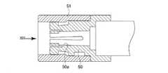
前述の通り、内視鏡用処置具装置10では、挿入部11の先端に対して、様々なタイプの先端処置部を取り付けることができる。図19は、把持鉗子に代えて高周波スネアの先端処置部113を取り付けた状態を示している。この先端処置部113は、処置具操作ワイヤ28のワイヤ先端部28aに接続するワイヤ接続部113aと、環状をなすループワイヤ部113bとを有している。ワイヤ接続部113aは、ワイヤガイド固定部材22と枠受け環23の内周面によって形成される進退ガイド孔26よりも小径で、図19に示す位置から右方へ移動してガイドチューブ29内へ入ることが可能である。ループワイヤ部113bは、その基端部付近が枠受け環23のテーパ内周面23dに接触することによって、その開口の大きさ(開度)が制御される。例えば、ワイヤ接続部113aが図19の位置よりも右手方向に移動されると、ループワイヤ部113bが挿入部11の内方に引き込まれてテーパ内周面23dに対する当接位置が変化する。その結果、ループワイヤ部113bの開口径が小さくなり、処置対象物を挟むことができる。なお、枠受け環23におけるループワイヤ部113bとの接触部を、先端側に進むにつれて開口径を徐々に大きくする部分円錐状のテーパ内周面23dとしたことで、ループワイヤ部113bが進退移動するときの抵抗や摩耗が抑制され、操作性や耐久性が向上している。  As described above, in the endoscopetreatment instrument device 10, various types of distal treatment sections can be attached to the distal end of theinsertion section 11. FIG. 19 shows a state in which a high-frequency snaretip treatment section 113 is attached instead of the grasping forceps. Thedistal treatment section 113 includes awire connection section 113a connected to the wiredistal end section 28a of the treatmentinstrument operation wire 28, and an annularloop wire section 113b. Thewire connecting portion 113a has a smaller diameter than the advance /retreat guide hole 26 formed by the wireguide fixing member 22 and the inner peripheral surface of theframe receiving ring 23, and moves to the right from the position shown in FIG. It is possible to enter. The size (opening) of the opening of theloop wire portion 113b is controlled by the vicinity of the base end portion of theloop wire portion 113b coming into contact with the tapered innerperipheral surface 23d of theframe receiving ring 23. For example, when thewire connecting portion 113a is moved in the right-hand direction from the position of FIG. 19, theloop wire portion 113b is drawn inward of theinsertion portion 11, and the contact position with respect to the tapered innerperipheral surface 23d is changed. As a result, the opening diameter of theloop wire portion 113b is reduced, and the treatment object can be sandwiched. In addition, the contact part with theloop wire part 113b in theframe receiving ring 23 is a partially conical tapered innerperipheral surface 23d whose opening diameter is gradually increased toward the tip side, so that theloop wire part 113b moves forward and backward. Resistance and wear are suppressed, and operability and durability are improved.

処置具操作ワイヤ28を挿入部11の軸線を中心として回転させると、先端処置部113は、ループワイヤ部113bをテーパ内周面23dに対して摺接させながら回転され、ループワイヤ部113bを含む平面の向きを変化させることができる。よって、先の把持鉗子の場合と同様に、湾曲部14を湾曲させたままで先端処置部113の向きを容易に調整することができる。この回転操作時にも、ループワイヤ部113bが摺接する対象が部分円錐状のテーパ内周面23dであるため、ループワイヤ部113bの摩耗などが生じにくく円滑な回転動作を行わせることができる。  When the treatmentinstrument operation wire 28 is rotated about the axis of theinsertion portion 11, thedistal treatment portion 113 is rotated while theloop wire portion 113b is in sliding contact with the tapered innerperipheral surface 23d, and includes theloop wire portion 113b. The orientation of the plane can be changed. Therefore, as in the case of the previous grasping forceps, the direction of thedistal treatment section 113 can be easily adjusted while thebending section 14 is bent. Even during this rotation operation, the object with which theloop wire portion 113b is slidably contacted is the partially conical tapered innerperipheral surface 23d, so that theloop wire portion 113b is less likely to be worn and can be smoothly rotated.

以上の内視鏡用処置具装置10では、挿入部11の先端を構成する先端硬性部材のうち、先端処置部13、113が接する枠受け環23をステンレスなどの金属で形成している。枠受け環23を金属製にしたことには次のようなメリットがある。挿入部11に対する先端処置部13(把持鉗子)の軸回りの回転動作時には、枠受け環23に対して回転自在枠24が相対回動する。金属製の枠受け環23は、耐摩耗性に優れており、回転自在枠24との相対回動の繰り返しによる劣化が起こりにくい。同様に、先端処置部113(高周波スネア)が挿入部11に対して軸回りに回転動作するときには、ループワイヤ部113bがテーパ内周面23dに対して摺接するが、金属製の枠受け環23には摺接の繰り返しによる摩耗が生じにくい。また、先端処置部113に関しては、ループワイヤ部113bの開口の大きさを変化させる際にも、ループワイヤ部113bとテーパ内周面23dとの間で摺動が生じるが、このときの耐摩耗性にも優れている。さらに、先端処置部113の使用時には、ループワイヤ部113bに高周波電流を流したときに火花が飛ぶおそれがあるが、ループワイヤ部113bに最も近い部材である枠受け環23が金属製であるため、火花による焼け焦げを防ぐことができる。  In the endoscopetreatment instrument device 10 described above, theframe receiving ring 23 with which thedistal treatment sections 13 and 113 are in contact among the distal rigid members constituting the distal end of theinsertion section 11 is formed of a metal such as stainless steel. The fact that theframe receiving ring 23 is made of metal has the following advantages. When the distal treatment section 13 (gripping forceps) rotates about the axis relative to theinsertion section 11, therotatable frame 24 rotates relative to theframe receiving ring 23. The metalframe receiving ring 23 is excellent in wear resistance, and hardly deteriorates due to repeated relative rotation with therotatable frame 24. Similarly, when the distal treatment section 113 (high-frequency snare) rotates about the axis relative to theinsertion section 11, theloop wire section 113b comes into sliding contact with the tapered innerperipheral surface 23d, but the metalframe receiving ring 23 Wear is not likely to occur due to repeated sliding contact. Further, regarding thedistal treatment section 113, when the size of the opening of theloop wire section 113b is changed, sliding occurs between theloop wire section 113b and the taper innerperipheral surface 23d. Also excellent in properties. Further, when thedistal treatment section 113 is used, a spark may fly when a high-frequency current is passed through theloop wire section 113b, but theframe receiving ring 23 that is the member closest to theloop wire section 113b is made of metal. Can prevent scorching due to sparks.

なお、枠受け環23の外側は絶縁チューブ19により被覆されているため、先端処置部に高周波電流を流した際に、金属製の枠受け環23の外周面が挿入対象に直接に触れて火傷などを生じさせるおそれがない。また、枠受け環23の後部には絶縁体からなるワイヤガイド固定部材22が設けられており、節輪60など挿入部14内の金属部品と枠受け環23との間は絶縁性が保たれ、枠受け環23からの電流が他の金属部品に流れるおそれがない。  Since the outer side of theframe receiving ring 23 is covered with an insulatingtube 19, the outer peripheral surface of the metalframe receiving ring 23 directly touches the insertion target when a high-frequency current is passed through the distal treatment section, and burns are caused. There is no risk of causing such as. Further, a wireguide fixing member 22 made of an insulator is provided at the rear portion of theframe receiving ring 23, and insulation between the metal parts in theinsertion portion 14 such as thenode ring 60 and theframe receiving ring 23 is maintained. The current from theframe receiving ring 23 does not flow to other metal parts.

また、処置具操作ワイヤ28が挿通されているガイドチューブ29は絶縁性の可撓性チューブからなるため、挿入部11から保持部12に至るまで、処置具操作ワイヤ28とその外側の部材とは絶縁されており、処置具操作ワイヤ28から直接に湾曲部14、可撓管部15あるいは保持部12内の金属部品に電流が流れるおそれもない。  Further, since theguide tube 29 through which the treatmentinstrument operation wire 28 is inserted is formed of an insulating flexible tube, the treatmentinstrument operation wire 28 and the members outside thereof are arranged from theinsertion portion 11 to the holdingportion 12. It is insulated, and there is no possibility that a current flows directly from the treatmentinstrument operation wire 28 to the metal part in the bendingportion 14, theflexible tube portion 15, or the holdingportion 12.

さらに、保持部12において、ガイドチューブ29の端部が固定されるチューブ固定環41は、合成樹脂製の絶縁体からなる保持部本体77に支持されているので、チューブ固定環41から可撓管接続部材76に電流が流れることがない。また、湾曲操作ワイヤ66を案内するコイルチューブ64は、保持部12内でチューブ固定環41が設けられた後端部まで延設されずに、湾曲操作グリップ17側に向けて取り回しされているので、チューブ固定環41からコイルチューブ64や湾曲操作ワイヤ66に電流が流れることもない。  Furthermore, since thetube fixing ring 41 to which the end portion of theguide tube 29 is fixed in the holdingportion 12 is supported by the holding portionmain body 77 made of a synthetic resin insulator, thetube fixing ring 41 and the flexible tube are supported. No current flows through the connectingmember 76. In addition, thecoil tube 64 that guides the bendingoperation wire 66 is not extended to the rear end portion where thetube fixing ring 41 is provided in the holdingportion 12 and is routed toward the bendingoperation grip 17 side. The current does not flow from thetube fixing ring 41 to thecoil tube 64 or thebending operation wire 66.

以上のように、内視鏡用処置具装置10では、高周波電流が流される処置具操作ワイヤ28と、間接的に高周波電流が流れる位置にある枠受け環23及びチューブ固定環41は、他の金属部材に対して全て絶縁された構造になっている。そのため、高周波スネアなどの電気処置具を使用する場合に、金属部材から高周波電流が流れて火傷などを引き起こすおそれがない。特に、従来の処置具では、湾曲部の湾曲状態で引っ張られて薄肉になった外皮部分や、可撓管部の外皮にスポット的にできてしまった孔を通して電流が外部にリークするおそれがあったが、本実施形態では、湾曲部14や可撓管部15内の金属部品自体に高周波電流が流れないように絶縁されているので、そのようなリスクを解消できる。  As described above, in the endoscopetreatment instrument device 10, the treatmentinstrument operation wire 28 through which a high-frequency current flows, theframe receiving ring 23 and thetube fixing ring 41 at positions where the high-frequency current flows indirectly, The structure is completely insulated from the metal member. Therefore, when using an electric treatment instrument such as a high-frequency snare, there is no possibility that a high-frequency current flows from the metal member and causes a burn or the like. In particular, in the conventional treatment instrument, there is a possibility that current leaks to the outside through a thinned outer skin portion pulled in a curved state of the curved portion or a hole formed in a spot shape on the outer skin of the flexible tube portion. However, in this embodiment, since it is insulated so that a high frequency current may not flow into the metal part itself in the bendingpart 14 or theflexible tube part 15, such a risk can be eliminated.

以上の実施形態では、挿入部11の先端硬性部材を構成するワイヤガイド固定部材22と枠受け環23は、環状凸部23aと環状凹部22aの間を接着剤で固定しているが、図20及び図21のように爪係合で一体化させることも可能である。すなわち、図20及び図21に示すワイヤガイド固定部材22は、環状凹部22aの底部付近に、内径サイズを拡大させた4つの爪係合凹部22bを周方向に略等間隔で有し、枠受け環23は、環状凸部23aの先端部付近の外周面に、外形サイズを拡大させた4つの係合爪23eを周方向に略等間隔で有している。係合爪23eは爪係合凹部22bに対して軸方向及び回転方向の移動が規制された状態で係合しており、これによってワイヤガイド固定部材22と枠受け環23が一体化されている。なお、爪係合凹部22bと係合爪23eの数は4つ以外であってもよいし、その形状も任意に設定できる。さらに、周方向に分割された形状の複数の爪係合凹部22bと複数の係合爪23eに換えて、周方向に連続する環状溝タイプの爪係合凹部と環状フランジ状の係合爪を係合させる態様も可能である。爪係合凹部と係合爪が環状である態様では、接着によって相対回転を規制することが好ましい。逆に言えば、図21に示す複数の爪係合凹部22bと複数の係合爪23eによる固定構造では、接着剤を用いずにワイヤガイド固定部材22と枠受け環23の回転方向及び軸方向の相対移動を規制することができるため、生産性に優れる。  In the above embodiment, the wireguide fixing member 22 and theframe receiving ring 23 constituting the distal end rigid member of theinsertion portion 11 are fixed between the annularconvex portion 23a and the annularconcave portion 22a with an adhesive. And it is also possible to integrate by nail | claw engagement like FIG. That is, the wireguide fixing member 22 shown in FIGS. 20 and 21 has fourclaw engaging recesses 22b having an enlarged inner diameter size at substantially equal intervals in the circumferential direction near the bottom of theannular recess 22a. Thering 23 has fourengaging claws 23e whose outer sizes are enlarged at substantially equal intervals in the circumferential direction on the outer peripheral surface near the tip of the annularconvex portion 23a. The engagingclaw 23e is engaged with theclaw engaging recess 22b in a state in which the movement in the axial direction and the rotational direction is restricted, whereby the wireguide fixing member 22 and theframe receiving ring 23 are integrated. . Note that the number of theclaw engaging recesses 22b and the engagingclaw 23e may be other than four, and the shapes thereof can be arbitrarily set. Furthermore, instead of the plurality of claw engagement recesses 22b and the plurality ofengagement claws 23e having a shape divided in the circumferential direction, a claw engagement recess of an annular groove type that is continuous in the circumferential direction and a ring flange-like engagement claw A mode of engagement is also possible. In an aspect in which the claw engaging recess and the engaging claw are annular, it is preferable to restrict relative rotation by adhesion. In other words, in the fixing structure including the plurality ofclaw engaging recesses 22b and the plurality of engagingclaw 23e shown in FIG. 21, the rotation direction and the axial direction of the wireguide fixing member 22 and theframe receiving ring 23 are not used. The relative movement can be regulated, so that productivity is excellent.

以上、図示実施形態を参照して本発明を説明したが、本発明は図示実施形態に限定されるものではない。例えば、実施形態においては把持鉗子タイプの先端処置部13と高周波スネアの先端処置部113を例示したが、さらに針状メスなど別種の先端処置部に交換可能であってもよい。  While the present invention has been described with reference to the illustrated embodiment, the present invention is not limited to the illustrated embodiment. For example, in the embodiment, the grasping forceps typedistal treatment section 13 and the high frequency snaredistal treatment section 113 are illustrated, but may be replaced with another kind of distal treatment section such as a needle knife.

本発明を適用した内視鏡用処置具装置の全体構造を示す図である。It is a figure which shows the whole structure of the treatment tool apparatus for endoscopes to which this invention is applied.図1の内視鏡用処置具装置において、処置具操作ハンドルと湾曲部操作部をそれぞれ操作したときの挿入部側における動作の対応関係を示す図である。FIG. 3 is a diagram illustrating a correspondence relationship between operations on an insertion portion side when a treatment tool operation handle and a bending portion operation unit are respectively operated in the endoscope treatment tool device of FIG. 1.図1の内視鏡用処置具装置において、処置具操作ハンドルを軸回りに約90度回転させて先端処置部の向きを変えた状態を示す図である。FIG. 2 is a view showing a state in which the direction of a distal treatment section is changed by rotating a treatment instrument operation handle about 90 degrees around an axis in the endoscope treatment instrument apparatus of FIG. 1.一部を断面として示した先端処置部付近の拡大図である。FIG. 5 is an enlarged view of the vicinity of a distal treatment portion, showing a part as a cross section.図4とは略直交する方向から見た、一部を断面として示した先端処置部付近の拡大図である。FIG. 5 is an enlarged view of the vicinity of the distal treatment section, partly shown as a cross section, viewed from a direction substantially orthogonal to FIG.図1の内視鏡用処置具装置における湾曲部と可撓管部の接続部分の側断面図である。It is a sectional side view of the connection part of the bending part and flexible tube part in the treatment tool apparatus for endoscopes of FIG.図1の内視鏡用処置具装置における保持部と処置具操作ハンドルの側断面図である。It is a sectional side view of the holding | maintenance part and treatment tool operation handle in the treatment tool apparatus for endoscopes of FIG.処置具操作ハンドルを取り外した状態の保持部の側断面図である。It is a sectional side view of the holding | maintenance part of a state which removed the treatment tool operation handle.図8のIX−IX線に沿う保持部後端付近の断面図である。It is sectional drawing of the holding part rear end vicinity which follows the IX-IX line of FIG.保持部側の連結口金への着脱可能状態にある、処置具操作ハンドルの口金連結体と締結環の側断面図である。It is a sectional side view of the base connection body and fastening ring of the treatment instrument operation handle in a state where it can be attached to and detached from the connection base on the holding part side.図10の矢印XIに沿って見た、着脱可能状態における口金連結体と締結環の正面図である。It is the front view of a nozzle | cap | die coupling body and a fastening ring in the detachable state seen along the arrow XI of FIG.保持部側の連結口金への締結状態にある、処置具操作ハンドルの口金連結体と締結環の側断面図である。It is a sectional side view of a base connector and a fastening ring of a treatment instrument operation handle in a fastening state to a connection base on the holding part side.図12の矢印XIIIに沿って見た、着脱可能状態における口金連結体と締結環の正面図である。FIG. 13 is a front view of the base connector and the fastening ring in a detachable state as seen along arrow XIII in FIG. 12.図1の内視鏡用処置具装置における湾曲操作グリップと保持部の側断面図である。It is a sectional side view of the bending operation grip and holding | maintenance part in the treatment tool apparatus for endoscopes of FIG.図14のXV−XV線に沿う湾曲操作部の断面図である。It is sectional drawing of the bending operation part which follows the XV-XV line | wire of FIG.図14の矢印XVIに沿って見た、湾曲操作グリップ先端付近の正面図である。FIG. 15 is a front view of the vicinity of the distal end of the bending operation grip as viewed along the arrow XVI in FIG. 14.図8のXVII−XVII線に沿う、湾曲操作グリップの角度調整支持機構部分の断面図である。It is sectional drawing of the angle adjustment support mechanism part of the bending operation grip which follows the XVII-XVII line of FIG.図17の状態から湾曲操作部の向きを約120度変位させた状態の、湾曲操作グリップの角度調整支持機構部分の断面図である。FIG. 18 is a cross-sectional view of an angle adjustment support mechanism portion of the bending operation grip in a state where the direction of the bending operation unit is displaced by about 120 degrees from the state of FIG. 17.先端処置部を高周波スネアに換装した態様を示す、内視鏡用処置具装置の挿入部先端付近の側断面図である。It is side sectional drawing of the insertion part front-end | tip vicinity of the treatment tool apparatus for endoscopes which shows the aspect which replaced the front-end | tip treatment part with the high frequency snare.枠受け環とワイヤガイド固定部材を係合爪で相対固定させた別実施形態を示す、挿入部先端付近の側断面図である。It is a sectional side view of the vicinity of the distal end of the insertion portion, showing another embodiment in which the frame receiving ring and the wire guide fixing member are relatively fixed by the engaging claws.図20のXXI−XXI線に沿う断面図である。It is sectional drawing which follows the XXI-XXI line of FIG.

符号の説明Explanation of symbols

10 内視鏡用処置具装置
11 挿入部
12 保持部
13 先端処置部
14 湾曲部
15 可撓管部
16 処置部操作ハンドル
17 湾曲操作グリップ
19 絶縁チューブ
20 網状管
21 被覆チューブ
22 ワイヤガイド固定部材
22a 環状凹部
22b 爪係合凹部
23 枠受け環(回転受け部)
23a 環状凸部
23b 枠支持孔(円形孔)
23c リング嵌合溝(環状溝)
23d テーパ内周面
23e 係合爪
24 回転自在枠
24a 後端円筒部(円筒部)
25 スナップリング(弾性環状体)
26 進退ガイド孔
27 スライド部材
28 処置具操作ワイヤ
28a ワイヤ先端部
29 ガイドチューブ(ワイヤガイド部材)
35 36 鉗子部材
39 開閉回動軸
40 固定ナット
41 チューブ固定環(中継環)
43 連結口金
44 補強パイプ
46 固定用端部材
46a 小径部
50 口金連結体
51 締結環
52 筒体
53 ワイヤ連結部材
53a ワイヤ端部支持孔
54 スライダ
54a 指掛け部
55 側方端子
56 指通しリング
60 節輪
61 リベット
63 ガイドコイル固定環
64 コイルチューブ
65 コイルチューブ固定板
66(66UD、66LR)湾曲操作ワイヤ
67 ワイヤ止め部材
68(68UD、68LR) プーリーワイヤ
69(69UD、69LR) プーリー
70 上下湾曲操作レバー(湾曲操作部材)
71 左右湾曲操作レバー(湾曲操作部材)
72 親板
75 基端部材
76 可撓管接続部材
77 保持部本体(保持部外観部材)
77a 回転支持筒
78 接続環
78a 回動ガイド孔(角度調整支持機構)
78b 78c 端壁(角度調整支持機構)
79 ガイドピン(角度調整支持機構)
80 下部ハウジング
81 中間ハウジング
82 プーリーハウジング
83a〜83h Oリング
84 通気口金
113 先端処置部
113a ワイヤ接続部
113b ループワイヤ部
DESCRIPTION OFSYMBOLS 10 Endoscopetreatment tool apparatus 11Insertion part 12 Holding |maintenance part 13End treatment part 14Bending part 15Flexible tube part 16 Treatment part operation handle 17Bending operation grip 19 Insulatingtube 20Reticulated tube 21Covering tube 22 Wireguide fixing member22a Annular recess 22bClaw engagement recess 23 Frame receiving ring (rotation receiving portion)
23a annularconvex part 23b frame support hole (circular hole)
23c Ring fitting groove (annular groove)
23d Taper innerperipheral surface23e Engaging claw 24Rotating frame 24a Rear end cylindrical portion (cylindrical portion)
25 Snap ring (elastic ring)
26 Advance /Retreat Guide Hole 27Slide Member 28 TreatmentTool Operation Wire28a Wire Tip 29 Guide Tube (Wire Guide Member)
35 36Forceps member 39 Opening /closing rotation shaft 40Fixing nut 41 Tube fixing ring (relay ring)
43connection base 44 reinforcingpipe 46 fixingend member 46asmall diameter part 50base connection body 51fastening ring 52cylinder 53wire connection member 53a wireend support hole 54slider 54afinger hook part 55side terminal 56finger threading ring 60node ring 61Rivet 63 Guidecoil fixing ring 64Coil tube 65 Coil tube fixing plate 66 (66UD, 66LR) bendingoperation wire 67 Wire stopper member 68 (68UD, 68LR) Pulley wire 69 (69UD, 69LR)Pulley 70 Vertical bending operation lever (curving Operation member)
71 Left / right bending operation lever (bending operation member)
72Base plate 75Base end member 76 Flexibletube connecting member 77 Holding portion main body (holding portion appearance member)
77aRotation support cylinder 78Connection ring 78a Rotation guide hole (angle adjustment support mechanism)
78b 78c End wall (Angle adjustment support mechanism)
79 Guide pin (Angle adjustment support mechanism)
80Lower housing 81Intermediate housing 82Pulley housings 83a to 83h O-ring 84Vent hole 113End treatment portion 113aWire connection portion 113b Loop wire portion

Claims (12)

Translated fromJapanese
可撓性を有する挿入部の先端に設けられ、挿入対象内での処置を行う先端処置部と;
上記挿入部内に挿通されて上記先端処置部に接続する処置部操作ワイヤと;
を有する内視鏡用処置具において、
上記挿入部先端の回転受け部に対して、上記先端処置部を上記挿入部の長手方向軸を中心として回転自在に支持させ、
上記処置部操作ワイヤに対して、上記挿入部の長手方向への進退移動と、上記挿入部の長手方向軸を中心とする回転とを選択して与え、該処置部操作ワイヤの回転によって上記先端処置部に上記回転動作を行わせる操作手段を備えたことを特徴とする内視鏡用処置具。
A distal treatment section provided at the distal end of the insertion section having flexibility, and performing a treatment within the insertion target;
A treatment portion operation wire inserted into the insertion portion and connected to the distal treatment portion;
In an endoscopic treatment instrument having
With respect to the rotation receiving portion at the distal end of the insertion portion, the distal treatment portion is supported rotatably about the longitudinal axis of the insertion portion,
The treatment portion operation wire is selectively given to the longitudinal movement of the insertion portion in the longitudinal direction and the rotation about the longitudinal axis of the insertion portion, and the distal end is obtained by the rotation of the treatment portion operation wire. An endoscopic treatment tool comprising operating means for causing the treatment section to perform the above-described rotation operation.
請求項1記載の内視鏡用処置具装置において、上記回転受け部は、挿入部の先端側に開口された円形孔を有し、該円形孔の内周面の一部に内径サイズを大きくした環状溝が形成され、
上記先端処置部は上記回転受け部の円形孔に相対回転自在に嵌る円筒部を有し、該円筒部の外面に、上記環状溝に弾性的に係合して上記円形孔から先端処置部を抜け止めさせる弾性環状体が支持されていることを特徴とする内視鏡用処置具。
2. The endoscopic treatment device according to claim 1, wherein the rotation receiving portion has a circular hole opened on a distal end side of the insertion portion, and an inner diameter size is increased in a part of an inner peripheral surface of the circular hole. An annular groove is formed,
The distal treatment section has a cylindrical portion that is relatively rotatably fitted in the circular hole of the rotation receiving portion, and the distal treatment section is elastically engaged with the annular groove on the outer surface of the cylindrical portion from the circular hole. A treatment instrument for an endoscope, characterized in that an elastic annular body for retaining is supported.
請求項1記載の内視鏡用処置具装置において、上記回転受け部は、挿入部の先端側に開口された円形孔を有し、
上記先端処置部は、
上記回転受け部の円形孔内に挿入されて上記処置部操作ワイヤに接続するワイヤ接続部と;
該ワイヤ接続端部から延設され上記円形孔から外方に突出し、該円形孔の開口縁部との接触によって開度が規制されるループワイヤ部と;
を有しており、
上記回転受け部の円形孔の開口縁部が、上記挿入部の先端側に進むにつれて徐々に開口径を大きくする部分円錐状のテーパ内周面となっていることを特徴とする内視鏡用処置具。
The endoscope treatment tool device according to claim 1, wherein the rotation receiving portion has a circular hole opened on a distal end side of the insertion portion,
The tip treatment section is
A wire connection portion inserted into the circular hole of the rotation receiving portion and connected to the treatment portion operation wire;
A loop wire portion extending from the wire connection end portion and projecting outward from the circular hole, the opening degree of which is regulated by contact with the opening edge of the circular hole;
Have
An opening edge portion of the circular hole of the rotation receiving portion is a partially conical tapered inner peripheral surface that gradually increases in opening diameter toward the distal end side of the insertion portion. Treatment tool.
請求項2または3記載の内視鏡用処置具装置において、上記回転受け部は金属材料からなり、該回転受け部の外側を絶縁性チューブで覆ったことを特徴とする内視鏡用処置具。The endoscopic treatment instrument device according to claim 2 or 3, wherein the rotation receiving portion is made of a metal material, and an outer side of the rotation receiving portion is covered with an insulating tube. .請求項4記載の内視鏡用処置具装置において、上記挿通部の長手方向に沿って配設され上記処置部操作ワイヤを摺動自在に挿通させるワイヤガイド部材を有し、上記回転受け部の後部に、このワイヤガイド部材の端部が接続固定される、絶縁材からなるワイヤガイド固定部材が固定されていることを特徴とする内視鏡用処置具。The endoscope treatment instrument device according to claim 4, further comprising a wire guide member that is disposed along a longitudinal direction of the insertion portion and that allows the treatment portion operation wire to be slidably inserted therein, and the rotation receiving portion of the rotation receiving portion. A treatment instrument for an endoscope, characterized in that a wire guide fixing member made of an insulating material, to which an end portion of the wire guide member is connected and fixed, is fixed to a rear portion.請求項5記載の内視鏡用処置具装置において、上記回転受け部と上記ワイヤガイド固定部材は、挿入部の長手方向軸を中心とする環状をなし互いに嵌合する環状凹部と環状凸部を有し、この環状凹部と環状凸部の対向周面上に形成した係合爪と爪係合凹部の係合により一体化されていることを特徴とする内視鏡用処置具。6. The endoscopic treatment instrument device according to claim 5, wherein the rotation receiving portion and the wire guide fixing member have an annular concave portion and an annular convex portion that are formed in an annular shape around the longitudinal axis of the insertion portion and are fitted to each other. A treatment instrument for an endoscope, which is integrated by engagement of an engagement claw and a claw engagement recess formed on opposing circumferential surfaces of the annular recess and the annular projection.請求項1ないし6のいずれか1項記載の内視鏡用処置具装置において、上記挿入部の基端部が接続する保持部を備え、上記操作手段は、該保持部から上位挿入部と反対方向に突出し、該突出方向への進退操作と、該突出方向を向く軸線を中心とした回転操作とが可能に支持された操作ハンドルからなり、該操作ハンドルに上記処置部操作ワイヤが接続されていることを特徴とする内視鏡用処置具。The endoscopic treatment device according to any one of claims 1 to 6, further comprising a holding portion to which a proximal end portion of the insertion portion is connected, wherein the operation means is opposite to the upper insertion portion from the holding portion. And an operation handle supported so as to be capable of advancing and retreating in the protruding direction and a rotating operation centered on the axis facing the protruding direction, and the treatment section operation wire is connected to the operating handle. An endoscopic treatment tool characterized by comprising:請求項7記載の内視鏡用処置具装置において、上記保持部は、
絶縁体からなる保持部外観部材と;
この保持部外観部材を貫通して支持され、保持部の内側で上記ワイヤガイド部材の端部が接続固定され、保持部の外側に上記操作ハンドルを接続させる連結口金を支持した中継環と;
を備え、
上記処置部操作ワイヤは、上記中継環を貫通して保持部外方に延出されて上記操作ハンドルに接続されることを特徴とする内視鏡用処置具。
The endoscope treatment tool device according to claim 7, wherein the holding portion is
A holding member exterior member made of an insulator;
A relay ring that is supported through the holding portion appearance member, the end portion of the wire guide member is connected and fixed inside the holding portion, and a coupling base that connects the operation handle to the outside of the holding portion;
With
The treatment instrument for an endoscope, wherein the treatment portion operation wire extends through the relay ring to the outside of the holding portion and is connected to the operation handle.
請求項7または8記載の内視鏡用処置具装置において、上記挿入部の先端付近の一部は上記長手方向軸に対して湾曲動作が可能な湾曲部であり、
上記保持部から、上記挿入部と上記操作ハンドルを結ぶ保持部軸線と略直交する方向に向けて、上記湾曲部を湾曲操作するための湾曲操作グリップが突設されていることを特徴とする内視鏡用処置具。
The endoscope treatment tool device according to claim 7 or 8, wherein a part of the insertion portion near the distal end is a bending portion capable of bending with respect to the longitudinal axis.
A bending operation grip for bending the bending portion protrudes from the holding portion in a direction substantially orthogonal to a holding portion axis line connecting the insertion portion and the operation handle. Endoscopic treatment tool.
請求項9記載の内視鏡用処置具装置において、上記湾曲部は異なる複数の方向に湾曲可能であり、上記保持部からの上記湾曲操作グリップの突設方向は、上記湾曲部のいずれかの湾曲方向と略一致していることを特徴とする内視鏡用処置具。The endoscope treatment instrument device according to claim 9, wherein the bending portion can be bent in a plurality of different directions, and a protruding direction of the bending operation grip from the holding portion is any of the bending portions. A treatment instrument for an endoscope characterized by being substantially coincident with a bending direction.請求項9または10記載の内視鏡用処置具装置において、上記保持部に対して上記湾曲操作グリップを、その突出方向の軸線を中心とする回転方向に角度調整可能に支持する角度調整支持機構を有していることを特徴とする内視鏡用処置具。11. The endoscope treatment tool device according to claim 9 or 10, wherein an angle adjustment support mechanism that supports the bending operation grip with respect to the holding portion so that the angle of the bending operation grip can be adjusted in a rotation direction about an axis in a protruding direction thereof. A treatment instrument for an endoscope, characterized by comprising:請求項9ないし11のいずれか1項記載の内視鏡用処置具装置において、上記湾曲操作グリップは、同一の回転軸を中心として回動可能な2つの湾曲操作部材を備え、一方の湾曲操作部材と他方の湾曲操作部材を回動操作したときに、上記湾曲部が互いに略直交する方向へ湾曲動作されることを特徴とする内視鏡用処置具。The endoscopic treatment instrument device according to any one of claims 9 to 11, wherein the bending operation grip includes two bending operation members rotatable about the same rotation axis, and one bending operation is performed. A treatment instrument for an endoscope, wherein when the member and the other bending operation member are rotated, the bending portions are bent in directions substantially orthogonal to each other.
JP2008035893A2008-02-182008-02-18 Endoscopic treatment instrument devicePendingJP2009189702A (en)

Priority Applications (1)

Application NumberPriority DateFiling DateTitle
JP2008035893AJP2009189702A (en)2008-02-182008-02-18 Endoscopic treatment instrument device

Applications Claiming Priority (1)

Application NumberPriority DateFiling DateTitle
JP2008035893AJP2009189702A (en)2008-02-182008-02-18 Endoscopic treatment instrument device

Publications (1)

Publication NumberPublication Date
JP2009189702Atrue JP2009189702A (en)2009-08-27

Family

ID=41072287

Family Applications (1)

Application NumberTitlePriority DateFiling Date
JP2008035893APendingJP2009189702A (en)2008-02-182008-02-18 Endoscopic treatment instrument device

Country Status (1)

CountryLink
JP (1)JP2009189702A (en)

Cited By (4)

* Cited by examiner, † Cited by third party
Publication numberPriority datePublication dateAssigneeTitle
JP2014161497A (en)*2013-02-252014-09-08Oita Seimitsu Industry Co LtdMinimally invasive surgical operation system
KR101885816B1 (en)2016-09-272018-08-07한국기계연구원Operation Needle Holder
KR20190096544A (en)*2018-02-092019-08-20한국기계연구원Apparatus for laparoscpoic surgery
EP4623795A1 (en)*2024-03-292025-10-01FUJIFILM CorporationOperating device for endoscope auxiliary tool

Citations (10)

* Cited by examiner, † Cited by third party
Publication numberPriority datePublication dateAssigneeTitle
JPS48103957A (en)*1972-03-091973-12-26
JPS628727A (en)*1985-07-031987-01-16株式会社町田製作所Endoscope
JPH04136386A (en)*1990-09-281992-05-11Oi Seisakusho Co LtdDoor hinge
JPH04361744A (en)*1991-06-071992-12-15Olympus Optical Co LtdHigh frequency excision and severance tool
JPH07275253A (en)*1994-04-051995-10-24Terumo CorpSurgical instrument
JPH10151137A (en)*1996-11-251998-06-09Olympus Optical Co LtdTreatment appliance for endoscope
JP3406703B2 (en)*1994-09-282003-05-12ペンタックス株式会社 Endoscope treatment tool
JP2006095146A (en)*2004-09-302006-04-13Pentax Corp Endoscope snare
JP2007215787A (en)*2006-02-172007-08-30Pentax Corp High frequency knife for endoscope
JP2007526042A (en)*2004-03-032007-09-13ジンテーズ ゲゼルシャフト ミト ベシュレンクテル ハフツング Bone anchoring means

Patent Citations (10)

* Cited by examiner, † Cited by third party
Publication numberPriority datePublication dateAssigneeTitle
JPS48103957A (en)*1972-03-091973-12-26
JPS628727A (en)*1985-07-031987-01-16株式会社町田製作所Endoscope
JPH04136386A (en)*1990-09-281992-05-11Oi Seisakusho Co LtdDoor hinge
JPH04361744A (en)*1991-06-071992-12-15Olympus Optical Co LtdHigh frequency excision and severance tool
JPH07275253A (en)*1994-04-051995-10-24Terumo CorpSurgical instrument
JP3406703B2 (en)*1994-09-282003-05-12ペンタックス株式会社 Endoscope treatment tool
JPH10151137A (en)*1996-11-251998-06-09Olympus Optical Co LtdTreatment appliance for endoscope
JP2007526042A (en)*2004-03-032007-09-13ジンテーズ ゲゼルシャフト ミト ベシュレンクテル ハフツング Bone anchoring means
JP2006095146A (en)*2004-09-302006-04-13Pentax Corp Endoscope snare
JP2007215787A (en)*2006-02-172007-08-30Pentax Corp High frequency knife for endoscope

Cited By (5)

* Cited by examiner, † Cited by third party
Publication numberPriority datePublication dateAssigneeTitle
JP2014161497A (en)*2013-02-252014-09-08Oita Seimitsu Industry Co LtdMinimally invasive surgical operation system
KR101885816B1 (en)2016-09-272018-08-07한국기계연구원Operation Needle Holder
KR20190096544A (en)*2018-02-092019-08-20한국기계연구원Apparatus for laparoscpoic surgery
KR102097782B1 (en)2018-02-092020-04-06한국기계연구원Apparatus for laparoscpoic surgery
EP4623795A1 (en)*2024-03-292025-10-01FUJIFILM CorporationOperating device for endoscope auxiliary tool

Similar Documents

PublicationPublication DateTitle
EP2596741B1 (en)Endoscope, and treatment instrument for endoscope
EP2540240B1 (en)Therapeutic tool for endoscopes
JP5617056B2 (en) Insert body, insertion device, rotation unit, rotational force transmission unit
JP3634644B2 (en) Endoscope operation part
JP2008173472A (en) MEDICAL DEVICE, ENDOSCOPE TREATMENT TOOL, AND ENDOSCOPE DEVICE
JP5253676B2 (en) Endoscope
EP3005967B1 (en)High frequency treatment tool
JP5860742B2 (en) Advancing / retreating aid for endoscopic treatment tools
EP2415408B1 (en)Treatment device
WO2012070570A1 (en)Balloon-equipped catheter having variable stiffness insertion section, and endoscope with second bendable section
EP3216380A1 (en)Assist tool and endoscope system
JP2009189702A (en) Endoscopic treatment instrument device
JP4706008B2 (en) Cardiac catheter
WO2019225102A1 (en)Tip cover device
JP4726009B2 (en) Cardiac catheter
JP6095864B2 (en) Advancement / retraction aid, endoscope, and endoscope system
JP6854932B2 (en) Endoscope
JP6230227B2 (en) Insertion device and endoscope
JP2009189703A (en) Endoscope aids
JP2010069108A (en)Endoscope
US11224331B2 (en)Advance and retreat assisting tool for treatment instrument and endoscope system
EP3490428B1 (en)Steerable catheter handle
JP6655396B2 (en) Treatment tool insertion tool
JP5653814B6 (en) Endoscopic high-frequency treatment instrument
JP5653814B2 (en) Endoscopic high-frequency treatment instrument

Legal Events

DateCodeTitleDescription
A711Notification of change in applicant

Free format text:JAPANESE INTERMEDIATE CODE: A712

Effective date:20100507

A521Written amendment

Free format text:JAPANESE INTERMEDIATE CODE: A821

Effective date:20100712

RD02Notification of acceptance of power of attorney

Free format text:JAPANESE INTERMEDIATE CODE: A7422

Effective date:20100712

A621Written request for application examination

Free format text:JAPANESE INTERMEDIATE CODE: A621

Effective date:20101008

A977Report on retrieval

Free format text:JAPANESE INTERMEDIATE CODE: A971007

Effective date:20120706

A131Notification of reasons for refusal

Free format text:JAPANESE INTERMEDIATE CODE: A131

Effective date:20120717

A02Decision of refusal

Free format text:JAPANESE INTERMEDIATE CODE: A02

Effective date:20121113


[8]ページ先頭

©2009-2025 Movatter.jp