JP2009189685A - Endoscope - Google Patents
EndoscopeDownload PDFInfo
- Publication number
- JP2009189685A JP2009189685AJP2008035755AJP2008035755AJP2009189685AJP 2009189685 AJP2009189685 AJP 2009189685AJP 2008035755 AJP2008035755 AJP 2008035755AJP 2008035755 AJP2008035755 AJP 2008035755AJP 2009189685 AJP2009189685 AJP 2009189685A
- Authority
- JP
- Japan
- Prior art keywords
- button
- endoscope
- image
- gripping
- suction
- Prior art date
- Legal status (The legal status is an assumption and is not a legal conclusion. Google has not performed a legal analysis and makes no representation as to the accuracy of the status listed.)
- Pending
Links
Images


Landscapes
- Instruments For Viewing The Inside Of Hollow Bodies (AREA)
- Endoscopes (AREA)
Abstract
Description
Translated fromJapanese本発明は、挿入部と把持部が同一直線状に位置しないタイプの内視鏡に関する。 The present invention relates to an endoscope of a type in which an insertion portion and a grip portion are not positioned on the same straight line.
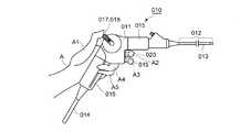
図7に示す鼻腔用の電子内視鏡010は、略くの字形状をなす操作把持部011と、操作把持部011から前方に延び、その先端部近傍部分が湾曲部013をなす挿入部012と、操作把持部011の下端部から延びるユニバーサルチューブ014と、を備えている。操作把持部011は、挿入部012の延長方向に沿って略前後方向に延びる操作部015と、操作部015の後部からから後ろ斜め下方に延びる把持部016と、を備えている。ユニバーサルチューブ014は図示を省略したプロセッサ(画像処理兼光源装置)と吸引源とに接続しており、プロセッサは図示を省略したモニタに接続している。
操作部015の後部には左右方向(操作部015の幅方向)に延びる回転軸(図示略)が操作部015に対して回転可能に設けてある。さらに、この回転軸の右端部(紙面の手前側の端部)には正面視略L字形をなす操作レバー017が固定してある。この操作レバー017は、操作部015の右側に位置しかつその基端部が上記回転軸の右端部に固定された径方向延出部018と、径方向延出部018の先端部から左側に延びる(紙面の手前側から紙面の裏面側に向かって紙面に直交する方向に延びる)被操作部(図示略)と、を有している。
さらに、操作部015の下部の前面には吸引ボタン019と画像処理ボタン020が出没可能に設けてある。An
A rotation shaft (not shown) extending in the left-right direction (width direction of the operation unit 015) is provided at the rear portion of the
Further, a
図示のように、術者は左手Aの掌を操作部015及び把持部016の左側面に被せ、薬指A4及び小指A5を把持部016の右側面に掛け、さらに親指A1を操作レバー017の被操作部に載せることにより電子内視鏡010を把持する。
術者が親指A1で被操作部(操作レバー017)を上方に回転操作すれば湾曲部013が下方に湾曲し、被操作部(操作レバー017)を下方に回転操作すれば湾曲部013が上方に湾曲する。
また、吸引ボタン019を後方に押すと、上記吸引源の吸引力が電子内視鏡010の内部に配設した吸引管(図示略)に及ぶので、挿入部012の先端面に形成した吸引口から患者の体液等を吸引可能となる。
さらに、挿入部012の先端面に設けた対物レンズ(図示略)によって得られた観察像を挿入部012の内部に設けた撮像素子で撮像すると、この観察像(動画)が上記モニタに表示される。そして、画像処理ボタン020を後方に押すと、画像処理ボタン020を押した瞬間に上記撮像素子が撮像した画像が静止画像として上記モニタに表示される。
If the surgeon rotates the operated portion (operation lever 017) upward with the thumb A1, the
Further, when the
Further, when an observation image obtained by an objective lens (not shown) provided on the distal end surface of the
図7の電子内視鏡010では、人差し指A2や中指A3によって吸引ボタン019や画像処理ボタン020を強い力で押すと、この力によって電子内視鏡010全体が不意にがたつくおそれがある。電子内視鏡010ががたつくと、モニタに表示された画像(動画)がぶれるおそれがある。さらに、画像処理ボタン020を押したときに電子内視鏡010が振動すると、モニタに表示された静止画像にぶれが生じるおそれがある。 In the
本発明は、操作把持部が屈曲しかつ操作部に内部装置または外部機器を操作するための操作ボタンを有する内視鏡を片手によって安定した状態で把持できるにした内視鏡を提供することを目的とする。 The present invention provides an endoscope in which an operation gripping portion is bent and an endoscope having an operation button for operating an internal device or an external device can be gripped in a stable state with one hand. Objective.
本発明の内視鏡は、略前後方向に延びる操作部、及び該操作部から後ろ斜め下方に向かって延びる把持部を有する操作把持部を備える内視鏡において、上記操作部の外面の上部及び下部に、上記把持部よりも前方に位置させて、上記内視鏡の内部装置または外部機器を操作するための操作ボタンをそれぞれ設けたことを特徴としている。 An endoscope according to the present invention includes an operation portion that extends substantially in the front-rear direction, and an operation gripping portion that has a gripping portion that extends obliquely rearward and downward from the operation portion, and an upper portion of the outer surface of the operation portion; Operation buttons for operating the internal device or the external device of the endoscope are provided in the lower part, positioned in front of the grip portion, respectively.
上記操作部の外面の上部と下部の少なくとも一方に、複数の上記操作ボタンを左右対称をなすように設けるのが好ましい。 It is preferable to provide a plurality of the operation buttons so as to be symmetric with respect to at least one of the upper part and the lower part of the outer surface of the operation part.
上記操作部に設けた左右方向に延びる回転軸を中心に回転可能で、かつ、該操作部の後面と対向する被操作部を有する操作レバーを設け、上記挿入部の一部を、上記操作レバーの回転操作に応じて湾曲する湾曲部としてもよい。 An operating lever having an operated portion that is rotatable about a rotation axis provided in the operating portion and extending in the left-right direction and that opposes the rear surface of the operating portion is provided. It is good also as a bending part which curves according to this rotation operation.
上記操作部の外面の下部に設けた上記操作ボタンを上下複数段に渡って設け、かつ、下方に位置する操作ボタンの前端面位置を上方に位置する操作ボタンの前端面位置より後退させるのが好ましい。 The operation button provided at the lower part of the outer surface of the operation unit is provided in a plurality of upper and lower stages, and the front end surface position of the operation button positioned below is moved backward from the front end surface position of the operation button positioned above. preferable.
本発明のように操作部の外面の上部及び下部に操作ボタンをそれぞれ設けると、片方の手で操作把持部を把持したときに、操作部の外面の上部に設けた操作ボタンに人差し指を掛け、操作部の外面の下部に設けた操作ボタンに中指(あるいは薬指、小指)を掛けることになる。すると、操作部の上部に指を掛けない場合に比べて把持状態が安定するので、仮に操作部の外面の下部に設けた操作ボタンを強い力で押しても内視鏡全体が不意にがたつくのを防止できる。そのため、操作ボタンを押した際に、モニタに表示された画像(動画)がぶれたり、画像処理ボタンを押すことにより得られる静止画像にぶれが生じるのを防止できる。 When the operation buttons are provided on the upper and lower portions of the outer surface of the operation portion as in the present invention, when the operation grip portion is gripped with one hand, the index finger is hung on the operation button provided on the upper portion of the outer surface of the operation portion, The middle finger (or ring finger, little finger) is put on the operation button provided on the lower part of the outer surface of the operation unit. As a result, the gripping state is more stable than when the finger is not placed on the upper part of the operation unit, so that even if the operation button provided on the lower part of the outer surface of the operation unit is pressed with a strong force, the entire endoscope will suddenly rattle. Can be prevented. Therefore, when the operation button is pressed, it is possible to prevent the image (moving image) displayed on the monitor from blurring or the still image obtained by pressing the image processing button from blurring.
請求項2のように構成すれば、右手と左手のいずれで把持する場合も、各操作ボタンを円滑に操作可能になる。 If comprised like Claim 2, even if it hold | grips with either the right hand or the left hand, it becomes possible to operate each operation button smoothly.
請求項3のように構成すれば、右手と左手のいずれで把持する場合も、操作レバーを円滑に操作できるようになる。 If comprised like Claim 3, even if it hold | grips with either the right hand or the left hand, an operation lever can be operated smoothly.
操作部の外面の下部に操作ボタンを上下複数段にわたって設けた場合は、下方の操作ボタンを操作しづらくなることがあるが、請求項4のように操作ボタンの前端面位置を上方から下方に向かうにつれて後退させれば、下方の操作ボタンも円滑に操作できる。 When the operation buttons are provided on the lower part of the outer surface of the operation unit in a plurality of upper and lower stages, it may be difficult to operate the lower operation buttons, but the front end face position of the operation buttons is changed from the upper side to the lower side as in claim 4. If it is retracted as it goes, the lower operation buttons can be operated smoothly.
以下、本発明の一実施形態を図1から図4を参照しながら説明する。なお、以下の説明中の前後方向は、内視鏡10の挿入部12の先端部側を「前方」、挿入部12の基端部側を「後方」と定義しており、左右方向は図3及び図4の矢印を基準にしている
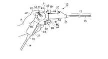
図1に示す内視鏡10は鼻腔用の電子内視鏡であり、側面視略くの字形状をなす操作把持部11と、操作把持部11の前端から前方に向かって延びる可撓性を有する挿入部12(挿入部12の前端部近傍部分が湾曲部13)と、操作把持部11の下端から挿入部12と反対側に延びるユニバーサルチューブ14と、を備えている。図示するように操作把持部11の下端面には切頭円錐形の筒状をなす折れ止めゴム15が設けてあり、この折れ止めゴム15がユニバーサルチューブ14の基端部(操作把持部11との接続部)の周囲を覆っている。ユニバーサルチューブ14は可撓性を有しており、その後端部に設けたコネクタ(図示略)が図示を省略したプロセッサ(画像処理装置兼光源装置)と吸引源に接続している。さらにプロセッサは図示を省略したモニタに接続しているので、挿入部12の先端面に設けた対物レンズ(図示略)によって得られた観察像を挿入部12の内部に設けた撮像素子で撮像すると、この観察像(動画)がモニタに表示される。Hereinafter, an embodiment of the present invention will be described with reference to FIGS. In the following description, the front-rear direction defines the distal end side of the
次に操作把持部11の構造について詳しく説明する。
操作把持部11は2つの大きな構成要素を具備している。即ち、略前後方向に延びると共に操作把持部11の上部をなす操作部20と、操作部20の後端部(下端部)から後ろ斜め下方に向かって延びる把持部21と、を具備している(図1及び図2に操作部20と把持部21の境界線BLを示す)。操作部20と把持部21は共に左右対称形状をなす中空の筒状部材であり、操作部20の下端部と把持部21の上端部は同じ断面形状の開口部となっている。そして、操作部20の下端部と把持部21の上端部を接合することにより操作把持部11を構成している。
操作部20は、後部22と、後部22より小径で後部22から前方に向かって延出する略円筒形状の前部23と、を有しており、後部22の左右両側面には側面視円形をなす垂直面である円形偏平面24が形成してある。
操作部20の右側の円形偏平面24には後部22の右側壁部を左右方向に貫通する回転軸25が設けてあり、回転軸25は把持部21の内部に設けた軸受けによってその軸線(左右方向に延びている)回りに回転可能に支持されている。この回転軸25の右端部には正面視略L字形状をなす操作レバー26の基端部が固定してある。操作レバー26は、側面視において円形偏平面24の径方向に延びかつその基端部が回転軸25の右端部に固定された径方向延出部27と、径方向延出部27の先端部から左側に向かって直線的に延びる被操作部28と、を有している。操作レバー26は回転軸25を中心に図示を省略した上限位置と下限位置の間を回転可能である。
さらに、操作部20の内部において回転軸25の周囲には捻りコイルばね(トーションばね)が設けてあり、この捻りコイルばねの端部が操作部20の内壁に係止してある。そのため、操作レバー26はこの捻りコイルばねの回転付勢力によって図1及び図2に示す初期位置に回転付勢(保持)されている。
図2に示すように術者が左手Aの親指A1を操作レバー26の被操作部28に載せて操作レバー26を上限位置側に回転させると、操作部20及び挿入部12の内部に配設した回転軸25と湾曲部13を連係する湾曲操作機構の働きにより湾曲部13が下方に湾曲する。一方、術者が親指A1で操作レバー26を下限位置側に回転させると湾曲操作機構の働きにより湾曲部13が上方に湾曲する。Next, the structure of the
The
The
A
Further, a torsion coil spring (torsion spring) is provided around the
As shown in FIG. 2, when the operator places the thumb A1 of the left hand A on the operated
操作部20の後部22の下部の前面には下側ボタン取付面30と、下側ボタン取付面30の直上に位置すると共に下側ボタン取付面30よりも前方に位置する上側ボタン取付面31と、が形成してある。図3に示すように、下側ボタン取付面30の左右方向の中央部には前後方向に出没自在である吸引ボタンB1が突設してあり、上側ボタン取付面31には共に前後方向に出没自在であるシャッターボタンB2と画像記憶ボタンB3が左右に並べて突設してある。さらに、操作部20の後部22の上部の前面には上部ボタン取付面32が形成してあり、この上部ボタン取付面32には画像エンハンスレベル変更ボタンB4と測光方式切替ボタンB5が左右に並べて突設してある。吸引ボタンB1を下側ボタン取付面30側に押し込むと、上記吸引源の吸引力が内視鏡10の内部に配設した吸引管(図示略)に及ぶので、挿入部12の先端面に形成した吸引口から患者の体液等を吸引可能となる。シャッターボタンB2を上側ボタン取付面31側に押し込むと、シャッターボタンB2を押した瞬間に上記撮像素子が撮像した画像が静止画像として上記モニタに表示される。さらに画像記憶ボタンB3を上側ボタン取付面31側に押し込むと、シャッターボタンB2を押し込むことにより得られた静止画像が上記プロセッサに内蔵した記憶手段に記憶される。画像エンハンスレベル変更ボタンB4を上部ボタン取付面32側に押し込んだ場合は画像エンハンスレベルが変更され、測光方式切替ボタンB5を上部ボタン取付面32側に押し込んだ場合は測光方式が切替わる。
図3に示すように、シャッターボタンB2と画像記憶ボタンB3は内視鏡10の左右方向の中心を通って上下方向に延びる中心線CL1に関して左右対称をなす位置に位置しており、画像エンハンスレベル変更ボタンB4と測光方式切替ボタンB5も中心線CL1に関して左右対称をなす位置に位置している。さらに、シャッターボタンB2と画像エンハンスレベル変更ボタンB4は正面視において前部23の中心を通って左右方向に延びる中心線CL2に関して上下対称をなす位置に位置しており、画像記憶ボタンB3と測光方式切替ボタンB5も中心線CL2に関して上下対称をなす位置に位置している。さらに、シャッターボタンB2、画像記憶ボタンB3、画像エンハンスレベル変更ボタンB4及び測光方式切替ボタンB5の外形は同一である。On the front surface of the lower portion of the
As shown in FIG. 3, the shutter button B2 and the image storage button B3 are located at positions that are symmetric with respect to a center line CL1 that extends in the up-down direction through the center in the left-right direction of the
次に、内視鏡10を術者が把持して使用する要領について説明する。
図2に示すように、術者が左手Aで操作部20及び把持部21を握る際には、操作部20及び把持部21の左側面に掌を接触させ、小指A5を把持部21の前側把持面35及び右側面に掛ける。さらに、薬指A4を吸引ボタンB1の前端面に接触させ、中指A3をシャッターボタンB2及び画像記憶ボタンB3の前端面に接触させ、人差し指A2を画像エンハンスレベル変更ボタンB4及び測光方式切替ボタンB5の前端面に接触させ、掌における親指A1に連なる部分(大菱形骨や舟状骨に対応する部分)あるいはその近傍を把持部21の後面に接触させる。
このように、人差し指A2を前部23の上方に位置する画像エンハンスレベル変更ボタンB4及び測光方式切替ボタンB5の前端面に接触させると、人差し指A2によって操作部20における前部23より上側の部分が支持されることになるので、前部23より上側の部分を支持せず前部23より下側の部分のみを支持する(吸引ボタンB1、シャッターボタンB2、画像記憶ボタンB3の前端面のみを指で押さえる)場合に比べて把持状態が安定する。従って、吸引ボタンB1、シャッターボタンB2、画像記憶ボタンB3、画像エンハンスレベル変更ボタンB4、測光方式切替ボタンB5を正確かつ円滑に操作できる。
さらに、前部23の上方に位置する画像エンハンスレベル変更ボタンB4及び測光方式切替ボタンB5を人差し指A2で押さえるので、仮に前部23の下方に位置するシャッターボタンB2を中指A3によって強い力で押しても内視鏡10全体が不意にがたつくことがない。そのため、シャッターボタンB2を押した際に、モニタに表示された画像(動画)がぶれたり、シャッターボタンB2を押すことにより得られる静止画像にぶれが生じるのを防止できる。Next, a procedure for the operator to grasp and use the
As shown in FIG. 2, when the operator holds the
As described above, when the index finger A2 is brought into contact with the front end surfaces of the image enhancement level change button B4 and the photometry method switching button B5 positioned above the
Further, since the image enhancement level change button B4 and the photometry switching button B5 positioned above the
また、シャッターボタンB2及び画像処理ボタンB3の上下方向位置と画像エンハンスレベル変更ボタンB4及び測光方式切替ボタンB5の上下方向位置が中心線CL2に関して上下対称となっているので、シャッターボタンB2、画像処理ボタンB3、画像エンハンスレベル変更ボタンB4及び測光方式切替ボタンB5を人差し指A2と中指A3で押さえ易い構造となっている。
さらに、吸引ボタンB1はシャッターボタンB2及び画像処理ボタンB3の直下に位置しているので、仮に吸引ボタンB1の前端面位置がシャッターボタンB2及び画像処理ボタンB3の前端面位置と同一あるいはシャッターボタンB2及び画像処理ボタンB3より前方に位置している場合は、吸引ボタンB1、シャッターボタンB2及び画像処理ボタンB3の操作が難しくなる。しかし、本実施形態ではシャッターボタンB2及び画像処理ボタンB3の前端面よりも吸引ボタンB1の前端面を後退させているので、吸引ボタンB1、シャッターボタンB2及び画像処理ボタンB3を円滑に押し操作できる。Further, since the vertical positions of the shutter button B2 and the image processing button B3 and the vertical positions of the image enhancement level change button B4 and the photometry method switching button B5 are vertically symmetrical with respect to the center line CL2, the shutter button B2, image processing The button B3, the image enhancement level change button B4, and the photometry method switching button B5 can be easily pressed with the index finger A2 and the middle finger A3.
Further, since the suction button B1 is located immediately below the shutter button B2 and the image processing button B3, the front end surface position of the suction button B1 is the same as the front end surface position of the shutter button B2 and the image processing button B3, or the shutter button B2 And when it is located in front of the image processing button B3, it becomes difficult to operate the suction button B1, the shutter button B2, and the image processing button B3. However, in the present embodiment, since the front end face of the suction button B1 is retracted from the front end faces of the shutter button B2 and the image processing button B3, the suction button B1, the shutter button B2, and the image processing button B3 can be smoothly pushed and operated. .
さらに、術者は右手によっても左手Aの場合と同様に内視鏡10を把持及び操作可能である。即ち、操作部20及び把持部21が左右対称形状をなしているので、術者は右手によっても操作把持部11を安定した状態で把持できる。さらに、吸引ボタンB1、シャッターボタンB2、画像記憶ボタンB3、画像エンハンスレベル変更ボタンB4、測光方式切替ボタンB5をそれぞれ中心線CL1に対して左右対称をなすように配置してあるので、右手で操作把持部11を把持した場合も吸引ボタンB1、シャッターボタンB2、画像記憶ボタンB3、画像エンハンスレベル変更ボタンB4、測光方式切替ボタンB5を正確かつ円滑に操作できる。また、操作レバー26の被操作部28は左右方向に長い部材なので、右手の親指によっても正確かつ円滑に操作できる。 Further, the operator can hold and operate the
以上、本発明を上記実施形態に基づいて説明したが、本発明は上記実施形態に限定されるものではなく様々な変形を施しながら実施可能である。
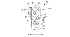
例えば、図5及び図6に示す内視鏡40のように操作部20の後部41の上部形状を内視鏡10の後部22と異ならせて実施してもよい(後部41の上部形状を除くと内視鏡10と同じ形状(構造)であり、内視鏡10と同じ形状(構造)の部材や構成要素には同じ符号を付してある)。
後部41の上面には同一形状の画像エンハンスレベル変更ボタンB6と測光方式切替ボタンB7が、中心線CL1に関して左右対称をなすように設けてある。画像エンハンスレベル変更ボタンB6はシャッターボタンB2と上下方向に並んでおり、測光方式切替ボタンB7は画像記憶ボタンB3と上下方向に並んでいる。この画像エンハンスレベル変更ボタンB6と測光方式切替ボタンB7はゴム製であり、その内面に一体的に突設した下向きの突起が後部41の内部に固定したスイッチ(図示略)の上面に接触している。そのため、画像エンハンスレベル変更ボタンB6と測光方式切替ボタンB7を真下に押圧した場合のみならず右斜め下方や左斜め下方など真下以外の方向に押圧した場合も、上記突起によってスイッチが押圧され所定の機能が発揮される。As mentioned above, although this invention was demonstrated based on the said embodiment, this invention is not limited to the said embodiment, It can implement, giving various deformation | transformation.
For example, the upper shape of the
On the upper surface of the
さらに、3つ以上の操作ボタンを左右方向に並べてもよい(好ましくは各操作ボタンが中心線CL1に関して左右対称をなすように配置する)。また、操作把持部11における前部23の上方と下方の一方のみに複数の操作ボタンを中心線CL1に対して左右対称をなすように設け、他方は左右対称とせずに設けても良い。
また、操作ボタンは上記の吸引ボタン、シャッターボタン、画像記憶ボタン等に限定されるものではなく、内視鏡の内部装置あるいは外部装置を遠隔操作するものであればどのような用途のボタンであってもよい。
また、上記実施形態の内視鏡10、内視鏡40は鼻腔内視鏡であるが、これとは用途の異なる内視鏡(例えば消化器用の内視鏡、工業用内視鏡など)や電子内視鏡ではない内視鏡にも本発明は適用可能である。Further, three or more operation buttons may be arranged in the left-right direction (preferably, each operation button is arranged so as to be symmetrical with respect to the center line CL1). Further, a plurality of operation buttons may be provided so as to be symmetric with respect to the center line CL1 only on one of the
Further, the operation buttons are not limited to the above-described suction button, shutter button, image storage button, etc., but can be used for any purpose as long as they remotely control the internal device or external device of the endoscope. May be.
In addition, although the
10 内視鏡
11 操作把持部
12 挿入部
13 湾曲部
14 ユニバーサルチューブ
15 折れ止めゴム
20 操作部
21 把持部
22 操作部の後部
23 操作部の前部
24 円形偏平面
25 回転軸
26 操作レバー
27 径方向延出部
28 被操作部
30 下側ボタン取付面
31 上側ボタン取付面
32 上部ボタン取付面
40 内視鏡
41 操作部の後部
A 左手
A1 親指
A2 人差し指
A3 中指
A4 薬指
A5 小指
B1 吸引ボタン(操作ボタン)
B2 シャッターボタン(操作ボタン)
B3 画像記憶ボタン(操作ボタン)
B4 画像エンハンスレベル変更ボタン(操作ボタン)
B5 測光方式切替ボタン(操作ボタン)
B6 画像エンハンスレベル変更ボタン(操作ボタン)
B7 測光方式切替ボタン(操作ボタン)
BL 操作部と把持部の境界線
CL1 内視鏡の左右方向の中心を通る中心線
CL2 操作部の前部の中心を通って上下方向に延びる中心線DESCRIPTION OF
B2 Shutter button (operation button)
B3 Image storage button (operation button)
B4 Image enhancement level change button (operation button)
B5 Metering mode switch button (operation button)
B6 Image enhancement level change button (operation button)
B7 Metering mode switching button (operation button)
BL Boundary line CL1 between the operation part and the grip part CL1 Center line that passes through the center in the left-right direction of the endoscope Center line that extends vertically through the center of the front part of the operation part
Claims (4)
Translated fromJapanese上記操作部の外面の上部及び下部に、上記把持部よりも前方に位置させて、上記内視鏡の内部装置または外部機器を操作するための操作ボタンをそれぞれ設けたことを特徴とする内視鏡。In an endoscope comprising an operation portion that extends substantially in the front-rear direction, and an operation gripping portion that has a gripping portion that extends obliquely rearward and downward from the operation portion.
An internal view characterized in that operation buttons for operating the internal device or external device of the endoscope are provided at an upper part and a lower part of the outer surface of the operation part, respectively, in front of the grip part. mirror.
上記操作部の外面の上部と下部の少なくとも一方に、複数の上記操作ボタンを左右対称をなすように設けた内視鏡。The endoscope according to claim 1, wherein
An endoscope in which a plurality of the operation buttons are provided so as to be symmetric with respect to at least one of an upper part and a lower part of an outer surface of the operation part.
上記操作部に設けた左右方向に延びる回転軸を中心に回転可能で、かつ、該操作部の後面と対向する被操作部を有する操作レバーを設け、
上記挿入部の一部を、上記操作レバーの回転操作に応じて湾曲する湾曲部とした内視鏡。The endoscope according to claim 1 or 2,
Provided with an operation lever that is rotatable about a rotation axis provided in the operation portion and extending in the left-right direction, and having an operated portion facing the rear surface of the operation portion;
An endoscope in which a part of the insertion portion is a bending portion that bends in response to a rotation operation of the operation lever.
上記操作部の外面の下部に設けた上記操作ボタンを上下複数段に渡って設け、かつ、下方に位置する操作ボタンの前端面位置を上方に位置する操作ボタンの前端面位置より後退させた内視鏡。The endoscope according to any one of claims 1 to 3,
The operation button provided at the lower part of the outer surface of the operation unit is provided in a plurality of upper and lower stages, and the front end surface position of the operation button located below is retracted from the front end surface position of the operation button located above. Endoscope.
Priority Applications (1)
| Application Number | Priority Date | Filing Date | Title |
|---|---|---|---|
| JP2008035755AJP2009189685A (en) | 2008-02-18 | 2008-02-18 | Endoscope |
Applications Claiming Priority (1)
| Application Number | Priority Date | Filing Date | Title |
|---|---|---|---|
| JP2008035755AJP2009189685A (en) | 2008-02-18 | 2008-02-18 | Endoscope |
Publications (1)
| Publication Number | Publication Date |
|---|---|
| JP2009189685Atrue JP2009189685A (en) | 2009-08-27 |
Family
ID=41072273
Family Applications (1)
| Application Number | Title | Priority Date | Filing Date |
|---|---|---|---|
| JP2008035755APendingJP2009189685A (en) | 2008-02-18 | 2008-02-18 | Endoscope |
Country Status (1)
| Country | Link |
|---|---|
| JP (1) | JP2009189685A (en) |
Cited By (9)
| Publication number | Priority date | Publication date | Assignee | Title |
|---|---|---|---|---|
| JP4897116B1 (en)* | 2010-12-24 | 2012-03-14 | オリンパス株式会社 | Endoscope device |
| JP4896273B1 (en)* | 2010-12-24 | 2012-03-14 | オリンパス株式会社 | Endoscope device |
| JP4897117B1 (en)* | 2010-12-24 | 2012-03-14 | オリンパス株式会社 | Endoscope device |
| US8177710B1 (en) | 2011-08-02 | 2012-05-15 | Olympus Corporation | Endoscopic device |
| US8182416B1 (en) | 2011-08-02 | 2012-05-22 | Olympus Corporation | Endoscopic device |
| US8840544B2 (en) | 2010-12-24 | 2014-09-23 | Olympus Corporation | Endoscope apparatus |
| JPWO2018066599A1 (en)* | 2016-10-05 | 2018-10-04 | オリンパス株式会社 | Insertion equipment |
| US10206559B2 (en) | 2014-06-20 | 2019-02-19 | Olympus Corporation | Endoscope apparatus |
| US10918267B2 (en) | 2016-02-18 | 2021-02-16 | Olympus Corporation | Endoscope |
- 2008
- 2008-02-18JPJP2008035755Apatent/JP2009189685A/enactivePending
Cited By (15)
| Publication number | Priority date | Publication date | Assignee | Title |
|---|---|---|---|---|
| US8911361B2 (en) | 2010-12-24 | 2014-12-16 | Olympus Corporation | Endoscope apparatus |
| US8758230B2 (en) | 2010-12-24 | 2014-06-24 | Olympus Corporation | Endoscope apparatus |
| JP4897117B1 (en)* | 2010-12-24 | 2012-03-14 | オリンパス株式会社 | Endoscope device |
| US8795160B2 (en) | 2010-12-24 | 2014-08-05 | Olympus Corporation | Endoscope apparatus |
| US8840544B2 (en) | 2010-12-24 | 2014-09-23 | Olympus Corporation | Endoscope apparatus |
| EP2636358A4 (en)* | 2010-12-24 | 2013-10-30 | Olympus Corp | Endoscopic device |
| JP4896273B1 (en)* | 2010-12-24 | 2012-03-14 | オリンパス株式会社 | Endoscope device |
| JP4897116B1 (en)* | 2010-12-24 | 2012-03-14 | オリンパス株式会社 | Endoscope device |
| US8182416B1 (en) | 2011-08-02 | 2012-05-22 | Olympus Corporation | Endoscopic device |
| US8177710B1 (en) | 2011-08-02 | 2012-05-15 | Olympus Corporation | Endoscopic device |
| US10206559B2 (en) | 2014-06-20 | 2019-02-19 | Olympus Corporation | Endoscope apparatus |
| US10918267B2 (en) | 2016-02-18 | 2021-02-16 | Olympus Corporation | Endoscope |
| JPWO2018066599A1 (en)* | 2016-10-05 | 2018-10-04 | オリンパス株式会社 | Insertion equipment |
| CN109715032A (en)* | 2016-10-05 | 2019-05-03 | 奥林巴斯株式会社 | Insertion instrument |
| CN109715032B (en)* | 2016-10-05 | 2021-10-08 | 奥林巴斯株式会社 | Insertion instrument |
Similar Documents
| Publication | Publication Date | Title |
|---|---|---|
| JP2009189685A (en) | Endoscope | |
| JP5006478B2 (en) | Endoscope | |
| JP6395973B1 (en) | Endoscope operation section and endoscope having the same | |
| JP5930255B2 (en) | Endoscope | |
| CN103517664B (en) | endoscope | |
| JP6017742B1 (en) | Endoscope operation unit and endoscope | |
| US8100825B2 (en) | Endoscope and supportive member for bending operation of the same | |
| JP6223648B1 (en) | Endoscope | |
| JP2006015078A (en) | Medical apparatus | |
| JP2009189684A (en) | Endoscope | |
| JPWO2014136470A1 (en) | Endoscope | |
| JP5567766B2 (en) | Endoscope | |
| JP5078260B2 (en) | Body cavity inspection device | |
| WO2015174128A1 (en) | Endoscope | |
| CN113329675B (en) | Endoscope with a lens | |
| JP3180423B2 (en) | Endoscope eyepiece | |
| JP2000254091A (en) | At-hand operating structure for endoscope | |
| US20240065534A1 (en) | Endoscope operation part and endoscope | |
| JP5872882B2 (en) | Endoscope | |
| WO2017126162A1 (en) | Portable endoscope | |
| JP2023080969A (en) | Endoscope | |
| JP2021164493A (en) | Endoscope operation unit, endoscope, and parent-child endoscope | |
| JPWO2015076018A1 (en) | Introduction device |