JP2009188474A - Audio playback device and control method thereof - Google Patents
Audio playback device and control method thereofDownload PDFInfo
- Publication number
- JP2009188474A JP2009188474AJP2008023471AJP2008023471AJP2009188474AJP 2009188474 AJP2009188474 AJP 2009188474AJP 2008023471 AJP2008023471 AJP 2008023471AJP 2008023471 AJP2008023471 AJP 2008023471AJP 2009188474 AJP2009188474 AJP 2009188474A
- Authority
- JP
- Japan
- Prior art keywords
- speaker
- sound
- signal
- audio
- audio signal
- Prior art date
- Legal status (The legal status is an assumption and is not a legal conclusion. Google has not performed a legal analysis and makes no representation as to the accuracy of the status listed.)
- Granted
Links
Images


Classifications
- H—ELECTRICITY
- H04—ELECTRIC COMMUNICATION TECHNIQUE
- H04R—LOUDSPEAKERS, MICROPHONES, GRAMOPHONE PICK-UPS OR LIKE ACOUSTIC ELECTROMECHANICAL TRANSDUCERS; DEAF-AID SETS; PUBLIC ADDRESS SYSTEMS
- H04R5/00—Stereophonic arrangements
- H04R5/04—Circuit arrangements, e.g. for selective connection of amplifier inputs/outputs to loudspeakers, for loudspeaker detection, or for adaptation of settings to personal preferences or hearing impairments
- H—ELECTRICITY
- H04—ELECTRIC COMMUNICATION TECHNIQUE
- H04S—STEREOPHONIC SYSTEMS
- H04S1/00—Two-channel systems
- H04S1/002—Non-adaptive circuits, e.g. manually adjustable or static, for enhancing the sound image or the spatial distribution
- H—ELECTRICITY
- H04—ELECTRIC COMMUNICATION TECHNIQUE
- H04R—LOUDSPEAKERS, MICROPHONES, GRAMOPHONE PICK-UPS OR LIKE ACOUSTIC ELECTROMECHANICAL TRANSDUCERS; DEAF-AID SETS; PUBLIC ADDRESS SYSTEMS
- H04R2499/00—Aspects covered by H04R or H04S not otherwise provided for in their subgroups
- H04R2499/10—General applications
- H04R2499/15—Transducers incorporated in visual displaying devices, e.g. televisions, computer displays, laptops
Landscapes
- Physics & Mathematics (AREA)
- Engineering & Computer Science (AREA)
- Acoustics & Sound (AREA)
- Signal Processing (AREA)
- Circuit For Audible Band Transducer (AREA)
- Details Of Audible-Bandwidth Transducers (AREA)
- Obtaining Desirable Characteristics In Audible-Bandwidth Transducers (AREA)
- Television Receiver Circuits (AREA)
- Stereophonic System (AREA)
Abstract
Translated fromJapaneseDescription
Translated fromJapanese本発明は、反射音の音響特性を分析することにより、複数のスピーカの出力特性を制御する音声再生装置及びその制御方法に関するものである。 The present invention relates to an audio reproduction device that controls output characteristics of a plurality of speakers by analyzing acoustic characteristics of reflected sound, and a control method therefor.
従来、低音再生用スピーカから出力される音は比較的指向性がないことを利用し、低音再生用のスピーカを側面に配置し、高音再生用のスピーカを正面に配置したスピーカ装置が知られている。このような配置とすることにより、良好な低音再生を実現し、かつ横幅を抑えたテレビジョン受像機用スピーカ装置が実現できる(特許文献1参照)。 2. Description of the Related Art Conventionally, there has been known a speaker device in which a low-frequency sound reproduction speaker is disposed on a side surface and a high-frequency sound reproduction speaker is disposed on the front surface, because the sound output from a low-frequency sound reproduction speaker is relatively non-directional. Yes. With such an arrangement, it is possible to realize a speaker device for a television receiver that realizes good bass reproduction and has a reduced horizontal width (see Patent Document 1).
また、測定音場に再生された測定信号を複数の指向軸を有する指向性マイクで収音し、方向毎に分析する音場測定装置が知られている。これにより、部屋の反射音成分を分析して、音場の空間性に関する拡がり感や残響感、音像の定位感などが評価できる(特許文献2参照)。
しかしながら、特許文献1のテレビジョン用受像機スピーカにおいては、スピーカユニットがテレビジョン用受像機の背面には配置されていないので、壁からの反射音を利用した音響システムとはならない。 However, in the television receiver speaker of
特許文献2の音場測定装置においては、マイクに複数の指向軸をもたせるためマイクの構成が複雑となる。また、マイクを聴取位置に配置して測定する必要があるため配線が長くなるとともに、装置全体が大型化して、取り扱いが煩雑になるという課題がある。マイクをリモコンなどの聴取位置にあるものに搭載することも可能であるが、この場合にはリモコン内にマイク増幅器やAD変換機が配置されるとともに、測定した多量のデータを送信する必要があり、リモコンの回路規模が大幅に増大する。また、リモコンがテーブルなどの平面に置かれると、マイクの特性に影響を与えるため、正確な測定が困難であるという課題がある。 In the sound field measuring apparatus of Patent Document 2, the microphone has a complicated configuration because the microphone has a plurality of directional axes. Moreover, since it is necessary to place the microphone at the listening position for measurement, the wiring becomes long, and the entire apparatus becomes large and handling becomes complicated. Although it is possible to mount a microphone at a listening position such as a remote control, in this case a microphone amplifier and AD converter are placed in the remote control and a large amount of measured data must be transmitted. The circuit scale of the remote control is greatly increased. In addition, when the remote control is placed on a flat surface such as a table, it affects the characteristics of the microphone, and there is a problem that accurate measurement is difficult.
本発明は、背面にスピーカを配置して壁からの反射音を利用した音響システムであって、コンパクトな構成で反射音の音響特性を分析可能とした音声再生装置を提供することを目的とする。 An object of the present invention is to provide an audio reproducing apparatus that uses a reflected sound from a wall by arranging a speaker on the back surface, and can analyze the acoustic characteristics of the reflected sound with a compact configuration. .
上記課題を解決するため、本発明の音声再生装置は、
第1のスピーカと、前記第1のスピーカとは異なる位置に配置された第2のスピーカとを有する音声再生装置であって、
前記第2のスピーカから出力される音声を入力して電気信号に変換するマイクと、
前記第2のスピーカに供給される第2の音声信号と前記マイクが出力する電気信号とから前記第2のスピーカから出力される音声の反射音の反射時間を検出する分析部と、
前記反射時間に基いて、前記第1のスピーカに供給される第1の音声信号及び前記第2の音声信号のうち少なくとも何れかの音声信号の位相を補正する位相補正部とを有することを特徴とする。In order to solve the above-described problem, an audio playback device according to the present invention provides:
An audio reproduction device having a first speaker and a second speaker arranged at a position different from the first speaker,
A microphone that inputs the sound output from the second speaker and converts it into an electrical signal;
An analysis unit for detecting a reflection time of a reflected sound of a sound output from the second speaker from a second sound signal supplied to the second speaker and an electric signal output from the microphone;
And a phase correction unit that corrects a phase of at least one of the first audio signal and the second audio signal supplied to the first speaker based on the reflection time. And
本発明の音声再生装置を搭載した平面型テレビジョン受像機が壁の前に設置された場合、壁面との距離や、壁面の音響反射特性が変化しても、反射音の影響による干渉や特性変動の少ない良好な音声再生が可能となる。 When a flat-screen television set equipped with the sound reproducing device of the present invention is installed in front of a wall, even if the distance to the wall surface or the acoustic reflection characteristics of the wall surface changes, interference and characteristics due to the influence of reflected sound Good audio reproduction with little fluctuation is possible.
以下、図面を参照して、本発明をその好適な実施形態に基づいて詳細に説明する。 Hereinafter, the present invention will be described in detail based on preferred embodiments with reference to the drawings.
図1は、本発明の音声再生装置のブロック図である。 FIG. 1 is a block diagram of an audio reproducing apparatus according to the present invention.
入力部16に入力された入力音声信号は、高域濾波部12と低域濾波部13にそれぞれ入力される。 The input audio signal input to the
制御部9の制御に基づいて、入力音声信号の、高域濾波部12は高域を、
低域濾波部13は低域をそれぞれフィルタリングして出力する。Based on the control of the control unit 9, the high-
The low-
位相補正部11は、制御部9の制御に基づいて、高域濾波部12の出力の位相を補正する。位相補正部11は低域濾波部13の出力の位相を補正する構成としても良し、両方の出力の位相を補正してもよい。 The
第1の音量調整部7は、制御部9の制御に基づいて、位相補正部11の出力振幅を調整する。 The first volume adjustment unit 7 adjusts the output amplitude of the
第2の音量調整部8は、制御部9の制御に基づいて、低域濾波部13の出力振幅を調整する。 The second volume adjustment unit 8 adjusts the output amplitude of the low-
第1の増幅部4は、第1の音量調整部7の出力を、メインスピーカ1(第1のスピーカに相当)が駆動できる出力レベルに増幅する。 The first amplifying
第2の増幅部5は、第2の音量調整部8の出力を、サブスピーカ2(第2のスピーカに相当)が駆動できる出力レベルに増幅する。 The second amplifying
第3の増幅部6は、マイク3の出力を、分析部10が分析できる出力レベルに増幅する。 The third amplification unit 6 amplifies the output of the
メインスピーカ1は、第1の増幅部4の出力である高域音声信号(第1の音声信号に相当)を可聴音に変換する。 The
サブスピーカ2は、第2の増幅部5の出力である低域音声信号(第2の音声信号に相当)を可聴音に変換する。 The sub-speaker 2 converts a low-frequency audio signal (corresponding to the second audio signal) that is the output of the second amplifying
マイク3は、サブスピーカ2が出力する音声、およびその反射音を入力して、電気信号に変換する。 The
分析部10は、第3の増幅部6の出力と、第2の増幅部5の出力を比較し、サブスピーカの位置からサブスピーカの出力音声を反射する物体までの距離や音響反射特性を分析する。 The
制御部9は、分析部10の分析結果に応じて、メインスピーカ1及びサブスピーカ2が出力する音声の周波数特性、位相特性、振幅特性を調節する。 The control unit 9 adjusts the frequency characteristic, phase characteristic, and amplitude characteristic of the sound output from the
以下、図2に示す本発明の音声再生装置の処理フロー図を用いて、音声再生装置の動作について詳細に説明する。 Hereinafter, the operation of the sound reproducing apparatus will be described in detail with reference to the processing flowchart of the sound reproducing apparatus of the present invention shown in FIG.
電源投入により処理が開始されると、第2の音量調整部8の出力調整値が特定の値に設定される(S1)。その結果、入力信号のうち低域濾波された信号が第2の増幅部5により増幅され、サブスピーカ2から出力される。 When the process is started by turning on the power, the output adjustment value of the second volume adjustment unit 8 is set to a specific value (S1). As a result, the low-pass filtered signal of the input signal is amplified by the
サブスピーカ2から出力された低域音声は、周囲に反射して反射音となる。マイク3により電気信号に変換された反射音は、分析部10により第2の増幅部5が出力する低域濾波信号と比較されて反射時間が算出される(S2)。 The low frequency sound output from the sub-speaker 2 is reflected around and becomes reflected sound. The reflected sound converted into the electric signal by the
制御部は、反射時間に基いて、聴取者に直接到達するメインスピーカ1の出力信号と、反射音となって到達するサブスピーカ2の出力信号が、位相差によって干渉しないよう、位相補正部11の特性を設定する(S3)。 Based on the reflection time, the
さらに分析部10は、マイク3の出力信号と、第2の増幅部5が出力する低域濾波信号とを比較して、反射音の音圧レベルと振幅周波数特性を分析する(S4)。 Further, the analyzing
制御部9は、音圧レベルと振幅周波数特性に応じて、反射音の音圧レベルが高いもしくは低域成分が多い場合には、低音過多となることを防ぐために、第2の音量調整部8の設定音量を小さくする(S5)。さらに、反射音に特定周波数成分が多い場合には、その周波数が過多となることを防ぐために、高域濾波部12と低域濾波部13のカットオフ周波数を調整する(S6)。以上の処理により、メインスピーカ1とサブスピーカ2の出力特性が適正に調整される。 In accordance with the sound pressure level and the amplitude frequency characteristic, the control unit 9 controls the second volume adjusting unit 8 to prevent the sound from being excessively low when the sound pressure level of the reflected sound is high or there are many low frequency components. The set volume is reduced (S5). Further, when there are many specific frequency components in the reflected sound, the cutoff frequencies of the high-
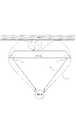
図3は、本発明の音声再生装置を、テレビジョン受像機に適用した場合の構成図である。サブスピーカ2が出力する信号の反射音を、効率良く電気信号に変換するために、マイク3をサブスピーカ2の近傍に配置している。 FIG. 3 is a configuration diagram when the audio reproduction apparatus of the present invention is applied to a television receiver. In order to efficiently convert the reflected sound of the signal output from the sub speaker 2 into an electric signal, the
図2のフローチャートを再度参照して、テレビジョン受像機の動作を説明する。平面型テレビジョン受像機が背面に壁がある状態で設置され、メインスピーカ1は、平面型テレビジョン受像機の前面側に、サブスピーカ2は背面側に配置される。 With reference to the flowchart of FIG. 2 again, the operation of the television receiver will be described. The flat television receiver is installed with a wall on the back, the
信号出力処理(S1)により、サブスピーカ2から出力された音声は、テレビジョン受信機後部の背面にある壁面を反射し反射音となり、マイク3へ入力する。反射音は、反射時間分析処理(S2)により、壁面との距離によって変化する反射音到達経路25の長さが算出される。制御部9には反射音到達経路25の長さに応じて、直接到達経路26と反射到達経路27の経路長の差を算出するための経路長差テーブルが記憶されている。 Through the signal output processing (S1), the sound output from the sub-speaker 2 is reflected on the wall surface on the back of the rear of the television receiver to become reflected sound and is input to the
経路長差テーブルを用いて、聴取者へ直接到達するメインスピーカ1の出力音声と、反射して到達するサブスピーカ2の出力音声が、経路長の差に起因する位相差による干渉を起こさないよう、出力音声の位相が調整される(S3)。 Using the path length difference table, the output sound of the
具体的には、図4(A)に示したように、直接到達経路26と反射到達経路27とで、音声が打ち消されるように干渉する場合には、図4(B)に示すように、互いに同位相となるようメインスピーカ1の出力音声の位相が補正される。 Specifically, as shown in FIG. 4A, when the
次に反射周波数特性分析処理(S4)により、壁面の音響反射率、反射周波数特性、およびサブスピーカ2と壁面の距離と空間波長の関係により変化する反射音の音圧レベルと周波数特性が分析される。 Next, the reflection frequency characteristic analysis process (S4) analyzes the acoustic reflectance of the wall surface, the reflection frequency characteristic, and the sound pressure level and frequency characteristic of the reflected sound that change depending on the relationship between the distance between the sub speaker 2 and the wall surface and the spatial wavelength. The
図5は、反射周波数特性分析処理(S4)の分析結果に応じて、音量調整制御処理(S5)および濾波特性制御処理(S6)によって設定される音声の再生特性例である。 FIG. 5 is an example of audio reproduction characteristics set by the volume adjustment control process (S5) and the filtering characteristic control process (S6) according to the analysis result of the reflection frequency characteristic analysis process (S4).
図5(a)のように、音声の反射レベルがほとんど周波数に依存しない場合は、サブスピーカとメインスピーカの信号レベルを等しくし、クロスオーバーレベルは中間値に設定される。 As shown in FIG. 5A, when the sound reflection level hardly depends on the frequency, the signal levels of the sub speaker and the main speaker are made equal, and the crossover level is set to an intermediate value.
図5(b)のように、反射音の低域成分が多い場合、又は音圧レベルが高い場合には、低音過多とならないように、第2の音量調整部8は、低域音声信号の信号レベルが小さくなるように入力信号を変調する。図5(c)のように、反射音に特定周波数成分が多い場合には、その周波数の音声が過多とならないように、制御部9は、高域濾波部12と低域濾波部13のカットオフ周波数を調整する。その結果、高域音声信号及び低域音声信号の周波数特性のクロスオーバーレベルが低レベル側に変調される。 As shown in FIG. 5B, when the low frequency component of the reflected sound is large or the sound pressure level is high, the second volume adjustment unit 8 prevents the low frequency sound signal from being excessive. The input signal is modulated so that the signal level becomes small. As shown in FIG. 5C, when there are many specific frequency components in the reflected sound, the control unit 9 cuts the high-
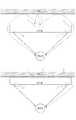
以上はステレオ構成のうち、右側のチャンネルのみの処理である。左側のチャンネルについては、第2のメインスピーカ17、第2のサブスピーカ22、第2のマイク28により、右側のチャンネルとは独立して同様の処理がなされる。左右のチャンネルについて独立して処理されるため、図6に示すように、テレビジョン受像機を壁面とが並行ではない状態で配置した場合であっても、本発明は容易に適用可能である。 The above is the processing of only the right channel in the stereo configuration. For the left channel, the same processing is performed independently of the right channel by the second
また、左右のチャンネルにおける反射音マイク到達経路25の長さの違いから、壁面との角度を算出することにより、より高精度な補正をすることも可能である。 It is also possible to perform more accurate correction by calculating the angle with the wall surface from the difference in the length of the reflected sound
以下、本発明に係る第2の実施形態について説明する。 Hereinafter, a second embodiment according to the present invention will be described.
図7は、本発明の第2の実施形態に係る音声再生装置のブロック図である。 FIG. 7 is a block diagram of an audio reproducing apparatus according to the second embodiment of the present invention.
測定に使用する基準信号を出力する基準信号発生部14と、制御部9の制御に基づいて、低域濾波部13と基準信号発生部14のいずれかの出力を選択して低域音声信号を出力する選択部15を有することを特徴とする。選択部15に係わる動作以外の動作については、実施例1と同様である。 Based on the control of the
電源投入により、制御部9は、基準信号発生部14の出力を選択するよう選択部15を制御する。その後、基準信号を用いて、図2のフローチャートに従った補正処理が、実施例1と同様に行われる。補正処理が終了した後、制御部9は、基準信号から低域濾波部13の出力信号に切り換えるように選択部15を制御する。 When the power is turned on, the control unit 9 controls the
基準信号は、時間的に一定振幅の信号レベルで、信号レベルの周波数依存性のない信号や信号レベルが周波数に比例する信号を用いることができる。 As the reference signal, a signal having a signal level having a constant amplitude in time and having no frequency dependency of the signal level or a signal having a signal level proportional to the frequency can be used.
本実施例では、信号レベルの安定した基準信号を用いて補正処理が行われるので、さらに精度の高い補正が可能となる。 In the present embodiment, correction processing is performed using a reference signal with a stable signal level, so that correction with higher accuracy is possible.
以下、本発明に係る第3の実施形態について説明する。 The third embodiment according to the present invention will be described below.
図8は、本発明の第3の実施形態に係る音声再生装置のブロック図である。 FIG. 8 is a block diagram of an audio reproducing apparatus according to the third embodiment of the present invention.
図9は、第3の実施形態における音声再生装置をテレビジョン受像機に適用した場合の構成図である。 FIG. 9 is a configuration diagram in the case where the sound reproducing device according to the third embodiment is applied to a television receiver.
ステレオ信号の左右チャンネルに対応して、第1の入力部16と第2の入力部22を有する、2.1チャンネルの構成である。サブスピーカ2は両チャンネル入力の低域を再生するサブウーハとし、第1のメインスピーカ1は右チャンネル入力の高域を、第2のメインスピーカ17は左チャンネル入力の高域を再生する。 This is a 2.1 channel configuration having a
選択部15により基準信号出力が選択されると、第2の実施例同様に、信号出力処理(S1)、反射時間分析処理(S2)されて、反射音マイク到達経路25の長さが認識されたのち、制御部9により、直接到達経路26と反射到達経路27が算出される。この算出結果に応じて位相制御処理(S3)されたのち、反射周波数特性分析処理(S4)、音量調整制御処理(S5)、濾波特性制御処理(S6)される。 When the reference signal output is selected by the
第1の入力部16および第2の入力部22から入力された音声信号は、低域濾波部13によりモノラルの低域信号に変換される。低域濾波信号出力処理(S7)により、左右の低域信号がサブスピーカ2から出力される。音の方向感覚は低域であるほど鈍感であるため、モノラルによる再生でも聴感上のステレオの分離には影響が少なく再生される。 The audio signals input from the
また、サブスピーカ2およびマイク3をそれぞれひとつづつで構成できるとともに、一連の処理を一度行うことにより反射音の影響による干渉や特性変動の少ないステレオ音声再生が可能となる。 Further, the sub-speaker 2 and the
以下、本発明に係る第4の実施形態について説明する。 The fourth embodiment according to the present invention will be described below.
図10は、本発明の第4の実施形態に係る音声再生装置のブロック図である。 FIG. 10 is a block diagram of an audio reproducing apparatus according to the fourth embodiment of the present invention.
図11は、第4の実施形態における音声再生装置をテレビジョン受像機に適用した場合の構成図である。 FIG. 11 is a configuration diagram in the case where the sound reproducing device according to the fourth embodiment is applied to a television receiver.
第1のサブスピーカ2とは異なる位置に第2のサブスピーカ22が配置されている。制御部9の制御に基づいて、第1のサブスピーカ2と第2のサブスピーカ22のいずれかを選択して第2の増幅部5の出力を供給する第2の選択部23を有することを特徴とする。 A
第1の選択部15により基準信号出力が選択されると、第2の実施例同様に、図2で示したフローチャートに従って動作する。反射時間分析処理(S2)の結果、反射時間が一定時間以内であるか、反射周波数特性分析処理(S4)の結果、反射レベルが一定の範囲以外であることを検出すると、制御部9はテレビジョン受像機が壁掛け状態で使用されていると判断する。このとき、第2の選択部23は、第2のサブスピーカ22を選択する。さらに、位相補正部11の特性、第2の音量調整部8の音量、高域濾波部12と低域濾波部13のカットオフ周波数が、第2のサブスピーカ22の特性に適した設定に切り換えられる。 When the reference signal output is selected by the
このとき、音の方向感覚は低域であるほど鈍感であるため、モノラルによる再生でも聴感上のステレオの分離には影響が少なく再生される。 At this time, since the sense of direction of the sound is insensitive as the frequency is low, reproduction with monaural sound is reproduced with little influence on stereo separation.
以上の処理により、テレビジョン受像機が壁掛け状態で使用された場合であっても、第2のサブスピーカ22の出力により適切に音声信号補正される。壁面とサブスピーカ2の間にある程度の間隔がある状態で使用された場合には、その距離や、壁面の音響反射特性が変化しても、反射音の影響による干渉や特性変動の少ない音声再生が可能となる。 By the above processing, even when the television receiver is used in a wall-mounted state, the audio signal is appropriately corrected by the output of the
以下、本発明に係る第5の実施形態について説明する。 The fifth embodiment according to the present invention will be described below.
図12は、本発明の第5の実施形態に係る音声再生装置のブロック図である。 FIG. 12 is a block diagram of an audio reproducing apparatus according to the fifth embodiment of the present invention.
図13は、第5の実施形態における音声再生装置をテレビジョン受像機に適用した場合の構成図である。 FIG. 13 is a configuration diagram when the sound reproducing device according to the fifth embodiment is applied to a television receiver.
実施例4と同様に、
第1のサブスピーカ2とは異なる位置に、第2のサブスピーカ22が配置されている。選択部23に変えて、第2の増幅部5の出力バランスを調整するバランス調整部24を有することを特徴とする。Similar to Example 4,
The
実施例4と同様、図2のフローチャートに従って、補正処理が行われる。 Similar to the fourth embodiment, correction processing is performed according to the flowchart of FIG.
反射時間分析処理(S2)の結果、反射時間が長いほど又は、反射周波数特性分析処理(S4)の結果、反射レベルが低いほど、制御部9は壁面の反射を利用した再生が困難であるか、又は壁面がないと判断する。このとき、第2のサブスピーカ22の再生レベルを上げる。音の方向感覚は低域であるほど鈍感であるため、モノラルによる再生でも聴感上のステレオの分離には影響が少なく再生される。 As a result of the reflection time analysis process (S2), the longer the reflection time is, or the lower the reflection level is as a result of the reflection frequency characteristic analysis process (S4), the more difficult the control unit 9 reproduces using the reflection of the wall surface. It is determined that there is no wall surface. At this time, the playback level of the
また、第2のサブスピーカ22の再生レベルに応じて、位相補正部11の特性、第2の音量調整部8の設定音量、高域濾波部12と低域濾波部13のカットオフ周波数を調整してもよい。 Further, according to the reproduction level of the
以上の処理により、テレビジョン受像機が、サブスピーカ2による壁面の反射を利用した再生が困難な状態で使用された場合であっても、第2のサブスピーカ22の出力により補正される。サブスピーカ2の背後にある程度の反射特性の壁面がある状態で使用された場合にはその距離や、壁面の音響反射特性が変化しても、反射音の影響による干渉や特性変動の少ない音声再生が可能となる。 By the above processing, even when the television receiver is used in a state where reproduction using the reflection of the wall surface by the sub speaker 2 is difficult, the television receiver is corrected by the output of the
1 メインスピーカ
2 サブスピーカ
3 マイク
4 第1の増幅部
5 第2の増幅部
6 第3の増幅部
7 第1の音量調整部
8 第2の音量調整部
9 制御部
10 分析部
11 位相補正部
12 高域濾波部
13 低域濾波部
14 基準信号発生部
15 選択部
16 入力部
17 第2のメインスピーカ
18 第4の増幅部
19 第3の音量調整部
20 第2の高域濾波部
21 第2の入力部
22 第2のサブスピーカ
23 第2の選択部
24 バランス調整部
25 反射音マイク到達経路
26 直接到達経路
27 反射到達経路
28 第2のマイク
S1 信号出力処理
S2 反射時間分析処理
S3 位相制御処理
S4 反射周波数特性分析処理
S5 音量調整制御処理
S6 濾波特性制御処理
S7 低域濾波信号出力処理DESCRIPTION OF
Claims (8)
Translated fromJapanese前記第2のスピーカから出力される音声を入力して電気信号に変換するマイクと、
前記第2のスピーカに供給される第2の音声信号と前記マイクが出力する電気信号とから前記第2のスピーカから出力される音声の反射音の反射時間を検出する分析部と、
前記反射時間に基いて、前記第1のスピーカに供給される第1の音声信号及び前記第2の音声信号のうち少なくとも何れかの音声信号の位相を補正する位相補正部とを有することを特徴とする音声再生装置。An audio reproduction device having a first speaker and a second speaker arranged at a position different from the first speaker,
A microphone that inputs the sound output from the second speaker and converts it into an electrical signal;
An analysis unit for detecting a reflection time of a reflected sound of a sound output from the second speaker from a second sound signal supplied to the second speaker and an electric signal output from the microphone;
And a phase correction unit that corrects a phase of at least one of the first audio signal and the second audio signal supplied to the first speaker based on the reflection time. An audio playback device.
前記分析部は、前記反射音の周波数特性を検出し、
前記第1の音量調整部及び前記第2の音量調整部の少なくとも何れかは、前記反射音の周波数特性に基いて、前記第1の音声信号の信号レベル及び前記第2の音声信号の信号レベルのうち少なくとも何れかを変調することを特徴とする請求項1又は2記載の音声再生装置。A first volume adjusting unit that modulates the signal level of the first audio signal; and a second volume adjusting unit that modulates the signal level of the second audio signal;
The analysis unit detects a frequency characteristic of the reflected sound,
At least one of the first sound volume adjustment unit and the second sound volume adjustment unit is configured such that the signal level of the first sound signal and the signal level of the second sound signal are based on the frequency characteristics of the reflected sound. The sound reproducing apparatus according to claim 1, wherein at least one of the plurality of signals is modulated.
前記基準信号と前記低域濾波部を通した音声信号とを選択して、前記第2の音声信号を出力する選択部とをさらに有することを特徴とする請求項5記載の音声再生装置。A reference signal generator for generating a reference signal having a constant amplitude;
6. The audio reproduction apparatus according to claim 5, further comprising a selection unit that selects the reference signal and an audio signal that has passed through the low-pass filtering unit and outputs the second audio signal.
前記第2のスピーカから出力される音声を入力して電気信号に変換するステップと、
前記第2のスピーカに供給される第2の音声信号と前記電気信号とから前記第2のスピーカから出力される音声の反射音の位相差を検出するステップと、
前記位相差に基いて、前記第1のスピーカに供給される第1の音声信号及び前記第2の音声信号のうち少なくとも何れかの音声信号の位相を補正するステップとを有することを特徴とする音声再生装置の制御方法。A method for controlling an audio reproduction device having a first speaker and a second speaker arranged at a position different from the first speaker,
Inputting the sound output from the second speaker and converting it into an electrical signal;
Detecting a phase difference between the reflected sound of the sound output from the second speaker from the second sound signal supplied to the second speaker and the electrical signal;
Correcting the phase of at least one of the first audio signal and the second audio signal supplied to the first speaker based on the phase difference. A method for controlling an audio playback device.
Priority Applications (2)
| Application Number | Priority Date | Filing Date | Title |
|---|---|---|---|
| JP2008023471AJP5043701B2 (en) | 2008-02-04 | 2008-02-04 | Audio playback device and control method thereof |
| US12/365,453US8175285B2 (en) | 2008-02-04 | 2009-02-04 | Audio player apparatus having sound analyzer and its control method |
Applications Claiming Priority (1)
| Application Number | Priority Date | Filing Date | Title |
|---|---|---|---|
| JP2008023471AJP5043701B2 (en) | 2008-02-04 | 2008-02-04 | Audio playback device and control method thereof |
Publications (3)
| Publication Number | Publication Date |
|---|---|
| JP2009188474Atrue JP2009188474A (en) | 2009-08-20 |
| JP2009188474A5 JP2009188474A5 (en) | 2011-03-17 |
| JP5043701B2 JP5043701B2 (en) | 2012-10-10 |
Family
ID=40931711
Family Applications (1)
| Application Number | Title | Priority Date | Filing Date |
|---|---|---|---|
| JP2008023471AExpired - Fee RelatedJP5043701B2 (en) | 2008-02-04 | 2008-02-04 | Audio playback device and control method thereof |
Country Status (2)
| Country | Link |
|---|---|
| US (1) | US8175285B2 (en) |
| JP (1) | JP5043701B2 (en) |
Cited By (33)
| Publication number | Priority date | Publication date | Assignee | Title |
|---|---|---|---|---|
| WO2012017518A1 (en)* | 2010-08-03 | 2012-02-09 | パイオニア株式会社 | Speaker system |
| WO2012017519A1 (en)* | 2010-08-03 | 2012-02-09 | パイオニア株式会社 | Speaker system |
| JP2014053684A (en)* | 2012-09-05 | 2014-03-20 | Jvc Kenwood Corp | Sound reproduction device, adjustment method and program |
| JP2017050843A (en)* | 2015-09-01 | 2017-03-09 | パナソニックIpマネジメント株式会社 | Signal processing method and speaker system |
| JP2017513433A (en)* | 2014-03-17 | 2017-05-25 | ソノズ インコーポレイテッド | Playback device settings based on proximity detection |
| US9936318B2 (en) | 2014-09-09 | 2018-04-03 | Sonos, Inc. | Playback device calibration |
| US9961463B2 (en) | 2012-06-28 | 2018-05-01 | Sonos, Inc. | Calibration indicator |
| US10045142B2 (en) | 2016-04-12 | 2018-08-07 | Sonos, Inc. | Calibration of audio playback devices |
| US10063983B2 (en) | 2016-01-18 | 2018-08-28 | Sonos, Inc. | Calibration using multiple recording devices |
| US10127006B2 (en) | 2014-09-09 | 2018-11-13 | Sonos, Inc. | Facilitating calibration of an audio playback device |
| US10127008B2 (en) | 2014-09-09 | 2018-11-13 | Sonos, Inc. | Audio processing algorithm database |
| US10129678B2 (en) | 2016-07-15 | 2018-11-13 | Sonos, Inc. | Spatial audio correction |
| US10129679B2 (en) | 2015-07-28 | 2018-11-13 | Sonos, Inc. | Calibration error conditions |
| US10129675B2 (en) | 2014-03-17 | 2018-11-13 | Sonos, Inc. | Audio settings of multiple speakers in a playback device |
| US10154359B2 (en) | 2014-09-09 | 2018-12-11 | Sonos, Inc. | Playback device calibration |
| US10284983B2 (en) | 2015-04-24 | 2019-05-07 | Sonos, Inc. | Playback device calibration user interfaces |
| US10299061B1 (en) | 2018-08-28 | 2019-05-21 | Sonos, Inc. | Playback device calibration |
| US10296282B2 (en) | 2012-06-28 | 2019-05-21 | Sonos, Inc. | Speaker calibration user interface |
| US10334386B2 (en) | 2011-12-29 | 2019-06-25 | Sonos, Inc. | Playback based on wireless signal |
| US10372406B2 (en) | 2016-07-22 | 2019-08-06 | Sonos, Inc. | Calibration interface |
| US10390161B2 (en) | 2016-01-25 | 2019-08-20 | Sonos, Inc. | Calibration based on audio content type |
| US10402154B2 (en) | 2016-04-01 | 2019-09-03 | Sonos, Inc. | Playback device calibration based on representative spectral characteristics |
| US10405116B2 (en) | 2016-04-01 | 2019-09-03 | Sonos, Inc. | Updating playback device configuration information based on calibration data |
| US10419864B2 (en) | 2015-09-17 | 2019-09-17 | Sonos, Inc. | Validation of audio calibration using multi-dimensional motion check |
| US10448194B2 (en) | 2016-07-15 | 2019-10-15 | Sonos, Inc. | Spectral correction using spatial calibration |
| US10459684B2 (en) | 2016-08-05 | 2019-10-29 | Sonos, Inc. | Calibration of a playback device based on an estimated frequency response |
| US10585639B2 (en) | 2015-09-17 | 2020-03-10 | Sonos, Inc. | Facilitating calibration of an audio playback device |
| US10599386B2 (en) | 2014-09-09 | 2020-03-24 | Sonos, Inc. | Audio processing algorithms |
| US10664224B2 (en) | 2015-04-24 | 2020-05-26 | Sonos, Inc. | Speaker calibration user interface |
| US10734965B1 (en) | 2019-08-12 | 2020-08-04 | Sonos, Inc. | Audio calibration of a portable playback device |
| US11106423B2 (en) | 2016-01-25 | 2021-08-31 | Sonos, Inc. | Evaluating calibration of a playback device |
| US11206484B2 (en) | 2018-08-28 | 2021-12-21 | Sonos, Inc. | Passive speaker authentication |
| US12322390B2 (en) | 2021-09-30 | 2025-06-03 | Sonos, Inc. | Conflict management for wake-word detection processes |
Families Citing this family (15)
| Publication number | Priority date | Publication date | Assignee | Title |
|---|---|---|---|---|
| JP5499469B2 (en)* | 2008-12-16 | 2014-05-21 | ソニー株式会社 | Audio output device, video / audio reproduction device, and audio output method |
| US20110176060A1 (en)* | 2010-01-21 | 2011-07-21 | Qualcomm Incorporated | Data feedback for broadcast applications |
| KR20110098103A (en)* | 2010-02-26 | 2011-09-01 | 삼성전자주식회사 | Display device and control method thereof |
| TWI486068B (en)* | 2010-09-13 | 2015-05-21 | Htc Corp | Mobile electronic device and sound playback method thereof |
| US8867749B2 (en)* | 2011-04-18 | 2014-10-21 | Paul Blair McGowan | Acoustic spatial projector |
| JP2015041814A (en)* | 2013-08-20 | 2015-03-02 | 船井電機株式会社 | Speaker attachment structure and display device |
| JP6090066B2 (en)* | 2013-08-28 | 2017-03-08 | ヤマハ株式会社 | Speaker device, audio playback system, and program |
| FR3015849B1 (en)* | 2013-12-19 | 2016-01-01 | Sagemcom Broadband Sas | SYSTEM COMPRISING AN ELECTRONIC APPARATUS AND A SUPPORT |
| US10057706B2 (en)* | 2014-11-26 | 2018-08-21 | Sony Interactive Entertainment Inc. | Information processing device, information processing system, control method, and program |
| US9930469B2 (en) | 2015-09-09 | 2018-03-27 | Gibson Innovations Belgium N.V. | System and method for enhancing virtual audio height perception |
| KR102419512B1 (en) | 2017-12-08 | 2022-07-12 | 삼성전자주식회사 | An electronic device comprising a plurality of speakers |
| CN108616791A (en)* | 2018-04-27 | 2018-10-02 | 青岛海信移动通信技术股份有限公司 | A kind of audio signal playing method and device |
| CN110234052B (en)* | 2019-07-23 | 2024-05-17 | 深圳市美妙之音科技有限公司 | 2.1 Sound track hand-held sound-amplifying microphone |
| KR102794749B1 (en)* | 2019-12-31 | 2025-04-14 | 삼성전자주식회사 | Display apparatus and sound outputting method thereof |
| CN115209077A (en)* | 2021-04-13 | 2022-10-18 | 华为技术有限公司 | Display apparatus and audio output method thereof |
Citations (4)
| Publication number | Priority date | Publication date | Assignee | Title |
|---|---|---|---|---|
| JPS59201600A (en)* | 1983-04-28 | 1984-11-15 | Mitsubishi Electric Corp | Color television receiver with built-in audio multiplexing |
| JP2004517563A (en)* | 2000-12-28 | 2004-06-10 | テレフオンアクチーボラゲツト エル エム エリクソン(パブル) | Acoustic-based proximity detector for use in mobile telephone equipment. |
| JP2004349793A (en)* | 2003-05-20 | 2004-12-09 | Yamaha Corp | Sound output system |
| JP2007243398A (en)* | 2006-03-07 | 2007-09-20 | Matsushita Electric Ind Co Ltd | Television receiver |
Family Cites Families (6)
| Publication number | Priority date | Publication date | Assignee | Title |
|---|---|---|---|---|
| US3581012A (en)* | 1967-07-13 | 1971-05-25 | Sony Corp | Unidirectional microphone |
| JP3303353B2 (en) | 1992-09-18 | 2002-07-22 | ソニー株式会社 | Speaker for television receiver |
| US6918461B2 (en)* | 2002-02-22 | 2005-07-19 | Cary L. Christie | Dual mono center channel |
| US7606372B2 (en)* | 2003-02-12 | 2009-10-20 | Fraunhofer-Gesellschaft Zur Foerderung Der Angewandten Forschung E.V. | Device and method for determining a reproduction position |
| JP4114583B2 (en) | 2003-09-25 | 2008-07-09 | ヤマハ株式会社 | Characteristic correction system |
| JP2007225482A (en) | 2006-02-24 | 2007-09-06 | Matsushita Electric Ind Co Ltd | Sound field measuring apparatus and sound field measuring method |
- 2008
- 2008-02-04JPJP2008023471Apatent/JP5043701B2/ennot_activeExpired - Fee Related
- 2009
- 2009-02-04USUS12/365,453patent/US8175285B2/ennot_activeExpired - Fee Related
Patent Citations (4)
| Publication number | Priority date | Publication date | Assignee | Title |
|---|---|---|---|---|
| JPS59201600A (en)* | 1983-04-28 | 1984-11-15 | Mitsubishi Electric Corp | Color television receiver with built-in audio multiplexing |
| JP2004517563A (en)* | 2000-12-28 | 2004-06-10 | テレフオンアクチーボラゲツト エル エム エリクソン(パブル) | Acoustic-based proximity detector for use in mobile telephone equipment. |
| JP2004349793A (en)* | 2003-05-20 | 2004-12-09 | Yamaha Corp | Sound output system |
| JP2007243398A (en)* | 2006-03-07 | 2007-09-20 | Matsushita Electric Ind Co Ltd | Television receiver |
Cited By (124)
| Publication number | Priority date | Publication date | Assignee | Title |
|---|---|---|---|---|
| WO2012017518A1 (en)* | 2010-08-03 | 2012-02-09 | パイオニア株式会社 | Speaker system |
| WO2012017519A1 (en)* | 2010-08-03 | 2012-02-09 | パイオニア株式会社 | Speaker system |
| US11889290B2 (en) | 2011-12-29 | 2024-01-30 | Sonos, Inc. | Media playback based on sensor data |
| US11825289B2 (en) | 2011-12-29 | 2023-11-21 | Sonos, Inc. | Media playback based on sensor data |
| US10455347B2 (en) | 2011-12-29 | 2019-10-22 | Sonos, Inc. | Playback based on number of listeners |
| US11910181B2 (en) | 2011-12-29 | 2024-02-20 | Sonos, Inc | Media playback based on sensor data |
| US10334386B2 (en) | 2011-12-29 | 2019-06-25 | Sonos, Inc. | Playback based on wireless signal |
| US11849299B2 (en) | 2011-12-29 | 2023-12-19 | Sonos, Inc. | Media playback based on sensor data |
| US11825290B2 (en) | 2011-12-29 | 2023-11-21 | Sonos, Inc. | Media playback based on sensor data |
| US11528578B2 (en) | 2011-12-29 | 2022-12-13 | Sonos, Inc. | Media playback based on sensor data |
| US10986460B2 (en) | 2011-12-29 | 2021-04-20 | Sonos, Inc. | Grouping based on acoustic signals |
| US11197117B2 (en) | 2011-12-29 | 2021-12-07 | Sonos, Inc. | Media playback based on sensor data |
| US11153706B1 (en) | 2011-12-29 | 2021-10-19 | Sonos, Inc. | Playback based on acoustic signals |
| US11122382B2 (en) | 2011-12-29 | 2021-09-14 | Sonos, Inc. | Playback based on acoustic signals |
| US10945089B2 (en) | 2011-12-29 | 2021-03-09 | Sonos, Inc. | Playback based on user settings |
| US11290838B2 (en) | 2011-12-29 | 2022-03-29 | Sonos, Inc. | Playback based on user presence detection |
| US11800305B2 (en) | 2012-06-28 | 2023-10-24 | Sonos, Inc. | Calibration interface |
| US12212937B2 (en) | 2012-06-28 | 2025-01-28 | Sonos, Inc. | Calibration state variable |
| US10129674B2 (en) | 2012-06-28 | 2018-11-13 | Sonos, Inc. | Concurrent multi-loudspeaker calibration |
| US11064306B2 (en) | 2012-06-28 | 2021-07-13 | Sonos, Inc. | Calibration state variable |
| US10045139B2 (en) | 2012-06-28 | 2018-08-07 | Sonos, Inc. | Calibration state variable |
| US10791405B2 (en) | 2012-06-28 | 2020-09-29 | Sonos, Inc. | Calibration indicator |
| US10284984B2 (en) | 2012-06-28 | 2019-05-07 | Sonos, Inc. | Calibration state variable |
| US10045138B2 (en) | 2012-06-28 | 2018-08-07 | Sonos, Inc. | Hybrid test tone for space-averaged room audio calibration using a moving microphone |
| US10412516B2 (en) | 2012-06-28 | 2019-09-10 | Sonos, Inc. | Calibration of playback devices |
| US11516608B2 (en) | 2012-06-28 | 2022-11-29 | Sonos, Inc. | Calibration state variable |
| US10296282B2 (en) | 2012-06-28 | 2019-05-21 | Sonos, Inc. | Speaker calibration user interface |
| US9961463B2 (en) | 2012-06-28 | 2018-05-01 | Sonos, Inc. | Calibration indicator |
| US11516606B2 (en) | 2012-06-28 | 2022-11-29 | Sonos, Inc. | Calibration interface |
| US10674293B2 (en) | 2012-06-28 | 2020-06-02 | Sonos, Inc. | Concurrent multi-driver calibration |
| US12069444B2 (en) | 2012-06-28 | 2024-08-20 | Sonos, Inc. | Calibration state variable |
| US11368803B2 (en) | 2012-06-28 | 2022-06-21 | Sonos, Inc. | Calibration of playback device(s) |
| US12126970B2 (en) | 2012-06-28 | 2024-10-22 | Sonos, Inc. | Calibration of playback device(s) |
| JP2014053684A (en)* | 2012-09-05 | 2014-03-20 | Jvc Kenwood Corp | Sound reproduction device, adjustment method and program |
| US10511924B2 (en) | 2014-03-17 | 2019-12-17 | Sonos, Inc. | Playback device with multiple sensors |
| JP2018164287A (en)* | 2014-03-17 | 2018-10-18 | ソノズ インコーポレイテッド | Playback device settings based on proximity detection |
| US10412517B2 (en) | 2014-03-17 | 2019-09-10 | Sonos, Inc. | Calibration of playback device to target curve |
| JP2017513433A (en)* | 2014-03-17 | 2017-05-25 | ソノズ インコーポレイテッド | Playback device settings based on proximity detection |
| US10051399B2 (en) | 2014-03-17 | 2018-08-14 | Sonos, Inc. | Playback device configuration according to distortion threshold |
| US11991505B2 (en) | 2014-03-17 | 2024-05-21 | Sonos, Inc. | Audio settings based on environment |
| US11540073B2 (en) | 2014-03-17 | 2022-12-27 | Sonos, Inc. | Playback device self-calibration |
| US11991506B2 (en) | 2014-03-17 | 2024-05-21 | Sonos, Inc. | Playback device configuration |
| US11696081B2 (en) | 2014-03-17 | 2023-07-04 | Sonos, Inc. | Audio settings based on environment |
| US12267652B2 (en) | 2014-03-17 | 2025-04-01 | Sonos, Inc. | Audio settings based on environment |
| US10129675B2 (en) | 2014-03-17 | 2018-11-13 | Sonos, Inc. | Audio settings of multiple speakers in a playback device |
| US10863295B2 (en) | 2014-03-17 | 2020-12-08 | Sonos, Inc. | Indoor/outdoor playback device calibration |
| US10791407B2 (en) | 2014-03-17 | 2020-09-29 | Sonon, Inc. | Playback device configuration |
| US10299055B2 (en) | 2014-03-17 | 2019-05-21 | Sonos, Inc. | Restoration of playback device configuration |
| US11625219B2 (en) | 2014-09-09 | 2023-04-11 | Sonos, Inc. | Audio processing algorithms |
| US10127006B2 (en) | 2014-09-09 | 2018-11-13 | Sonos, Inc. | Facilitating calibration of an audio playback device |
| US9936318B2 (en) | 2014-09-09 | 2018-04-03 | Sonos, Inc. | Playback device calibration |
| US10127008B2 (en) | 2014-09-09 | 2018-11-13 | Sonos, Inc. | Audio processing algorithm database |
| US10701501B2 (en) | 2014-09-09 | 2020-06-30 | Sonos, Inc. | Playback device calibration |
| US10599386B2 (en) | 2014-09-09 | 2020-03-24 | Sonos, Inc. | Audio processing algorithms |
| US10154359B2 (en) | 2014-09-09 | 2018-12-11 | Sonos, Inc. | Playback device calibration |
| US12141501B2 (en) | 2014-09-09 | 2024-11-12 | Sonos, Inc. | Audio processing algorithms |
| US10271150B2 (en) | 2014-09-09 | 2019-04-23 | Sonos, Inc. | Playback device calibration |
| US11029917B2 (en) | 2014-09-09 | 2021-06-08 | Sonos, Inc. | Audio processing algorithms |
| US10664224B2 (en) | 2015-04-24 | 2020-05-26 | Sonos, Inc. | Speaker calibration user interface |
| US10284983B2 (en) | 2015-04-24 | 2019-05-07 | Sonos, Inc. | Playback device calibration user interfaces |
| US10129679B2 (en) | 2015-07-28 | 2018-11-13 | Sonos, Inc. | Calibration error conditions |
| US10462592B2 (en) | 2015-07-28 | 2019-10-29 | Sonos, Inc. | Calibration error conditions |
| JP2017050843A (en)* | 2015-09-01 | 2017-03-09 | パナソニックIpマネジメント株式会社 | Signal processing method and speaker system |
| US11803350B2 (en) | 2015-09-17 | 2023-10-31 | Sonos, Inc. | Facilitating calibration of an audio playback device |
| US11706579B2 (en) | 2015-09-17 | 2023-07-18 | Sonos, Inc. | Validation of audio calibration using multi-dimensional motion check |
| US11099808B2 (en) | 2015-09-17 | 2021-08-24 | Sonos, Inc. | Facilitating calibration of an audio playback device |
| US12238490B2 (en) | 2015-09-17 | 2025-02-25 | Sonos, Inc. | Validation of audio calibration using multi-dimensional motion check |
| US12282706B2 (en) | 2015-09-17 | 2025-04-22 | Sonos, Inc. | Facilitating calibration of an audio playback device |
| US10419864B2 (en) | 2015-09-17 | 2019-09-17 | Sonos, Inc. | Validation of audio calibration using multi-dimensional motion check |
| US10585639B2 (en) | 2015-09-17 | 2020-03-10 | Sonos, Inc. | Facilitating calibration of an audio playback device |
| US11197112B2 (en) | 2015-09-17 | 2021-12-07 | Sonos, Inc. | Validation of audio calibration using multi-dimensional motion check |
| US10063983B2 (en) | 2016-01-18 | 2018-08-28 | Sonos, Inc. | Calibration using multiple recording devices |
| US11432089B2 (en) | 2016-01-18 | 2022-08-30 | Sonos, Inc. | Calibration using multiple recording devices |
| US10841719B2 (en) | 2016-01-18 | 2020-11-17 | Sonos, Inc. | Calibration using multiple recording devices |
| US11800306B2 (en) | 2016-01-18 | 2023-10-24 | Sonos, Inc. | Calibration using multiple recording devices |
| US10405117B2 (en) | 2016-01-18 | 2019-09-03 | Sonos, Inc. | Calibration using multiple recording devices |
| US11006232B2 (en) | 2016-01-25 | 2021-05-11 | Sonos, Inc. | Calibration based on audio content |
| US11184726B2 (en) | 2016-01-25 | 2021-11-23 | Sonos, Inc. | Calibration using listener locations |
| US10390161B2 (en) | 2016-01-25 | 2019-08-20 | Sonos, Inc. | Calibration based on audio content type |
| US10735879B2 (en) | 2016-01-25 | 2020-08-04 | Sonos, Inc. | Calibration based on grouping |
| US11106423B2 (en) | 2016-01-25 | 2021-08-31 | Sonos, Inc. | Evaluating calibration of a playback device |
| US11516612B2 (en) | 2016-01-25 | 2022-11-29 | Sonos, Inc. | Calibration based on audio content |
| US10402154B2 (en) | 2016-04-01 | 2019-09-03 | Sonos, Inc. | Playback device calibration based on representative spectral characteristics |
| US11995376B2 (en) | 2016-04-01 | 2024-05-28 | Sonos, Inc. | Playback device calibration based on representative spectral characteristics |
| US12302075B2 (en) | 2016-04-01 | 2025-05-13 | Sonos, Inc. | Updating playback device configuration information based on calibration data |
| US11736877B2 (en) | 2016-04-01 | 2023-08-22 | Sonos, Inc. | Updating playback device configuration information based on calibration data |
| US10880664B2 (en) | 2016-04-01 | 2020-12-29 | Sonos, Inc. | Updating playback device configuration information based on calibration data |
| US11379179B2 (en) | 2016-04-01 | 2022-07-05 | Sonos, Inc. | Playback device calibration based on representative spectral characteristics |
| US10405116B2 (en) | 2016-04-01 | 2019-09-03 | Sonos, Inc. | Updating playback device configuration information based on calibration data |
| US10884698B2 (en) | 2016-04-01 | 2021-01-05 | Sonos, Inc. | Playback device calibration based on representative spectral characteristics |
| US11212629B2 (en) | 2016-04-01 | 2021-12-28 | Sonos, Inc. | Updating playback device configuration information based on calibration data |
| US11218827B2 (en) | 2016-04-12 | 2022-01-04 | Sonos, Inc. | Calibration of audio playback devices |
| US11889276B2 (en) | 2016-04-12 | 2024-01-30 | Sonos, Inc. | Calibration of audio playback devices |
| US10750304B2 (en) | 2016-04-12 | 2020-08-18 | Sonos, Inc. | Calibration of audio playback devices |
| US10299054B2 (en) | 2016-04-12 | 2019-05-21 | Sonos, Inc. | Calibration of audio playback devices |
| US10045142B2 (en) | 2016-04-12 | 2018-08-07 | Sonos, Inc. | Calibration of audio playback devices |
| US12143781B2 (en) | 2016-07-15 | 2024-11-12 | Sonos, Inc. | Spatial audio correction |
| US11736878B2 (en) | 2016-07-15 | 2023-08-22 | Sonos, Inc. | Spatial audio correction |
| US10129678B2 (en) | 2016-07-15 | 2018-11-13 | Sonos, Inc. | Spatial audio correction |
| US11337017B2 (en) | 2016-07-15 | 2022-05-17 | Sonos, Inc. | Spatial audio correction |
| US12170873B2 (en) | 2016-07-15 | 2024-12-17 | Sonos, Inc. | Spatial audio correction |
| US10750303B2 (en) | 2016-07-15 | 2020-08-18 | Sonos, Inc. | Spatial audio correction |
| US10448194B2 (en) | 2016-07-15 | 2019-10-15 | Sonos, Inc. | Spectral correction using spatial calibration |
| US10853022B2 (en) | 2016-07-22 | 2020-12-01 | Sonos, Inc. | Calibration interface |
| US10372406B2 (en) | 2016-07-22 | 2019-08-06 | Sonos, Inc. | Calibration interface |
| US11531514B2 (en) | 2016-07-22 | 2022-12-20 | Sonos, Inc. | Calibration assistance |
| US11237792B2 (en) | 2016-07-22 | 2022-02-01 | Sonos, Inc. | Calibration assistance |
| US11983458B2 (en) | 2016-07-22 | 2024-05-14 | Sonos, Inc. | Calibration assistance |
| US11698770B2 (en) | 2016-08-05 | 2023-07-11 | Sonos, Inc. | Calibration of a playback device based on an estimated frequency response |
| US10459684B2 (en) | 2016-08-05 | 2019-10-29 | Sonos, Inc. | Calibration of a playback device based on an estimated frequency response |
| US10853027B2 (en) | 2016-08-05 | 2020-12-01 | Sonos, Inc. | Calibration of a playback device based on an estimated frequency response |
| US12260151B2 (en) | 2016-08-05 | 2025-03-25 | Sonos, Inc. | Calibration of a playback device based on an estimated frequency response |
| US10848892B2 (en) | 2018-08-28 | 2020-11-24 | Sonos, Inc. | Playback device calibration |
| US11206484B2 (en) | 2018-08-28 | 2021-12-21 | Sonos, Inc. | Passive speaker authentication |
| US11877139B2 (en) | 2018-08-28 | 2024-01-16 | Sonos, Inc. | Playback device calibration |
| US12167222B2 (en) | 2018-08-28 | 2024-12-10 | Sonos, Inc. | Playback device calibration |
| US10299061B1 (en) | 2018-08-28 | 2019-05-21 | Sonos, Inc. | Playback device calibration |
| US10582326B1 (en) | 2018-08-28 | 2020-03-03 | Sonos, Inc. | Playback device calibration |
| US11350233B2 (en) | 2018-08-28 | 2022-05-31 | Sonos, Inc. | Playback device calibration |
| US11728780B2 (en) | 2019-08-12 | 2023-08-15 | Sonos, Inc. | Audio calibration of a portable playback device |
| US12132459B2 (en) | 2019-08-12 | 2024-10-29 | Sonos, Inc. | Audio calibration of a portable playback device |
| US10734965B1 (en) | 2019-08-12 | 2020-08-04 | Sonos, Inc. | Audio calibration of a portable playback device |
| US11374547B2 (en) | 2019-08-12 | 2022-06-28 | Sonos, Inc. | Audio calibration of a portable playback device |
| US12322390B2 (en) | 2021-09-30 | 2025-06-03 | Sonos, Inc. | Conflict management for wake-word detection processes |
Also Published As
| Publication number | Publication date |
|---|---|
| JP5043701B2 (en) | 2012-10-10 |
| US8175285B2 (en) | 2012-05-08 |
| US20090196440A1 (en) | 2009-08-06 |
Similar Documents
| Publication | Publication Date | Title |
|---|---|---|
| JP5043701B2 (en) | Audio playback device and control method thereof | |
| JP4361354B2 (en) | Automatic sound field correction apparatus and computer program therefor | |
| US8761408B2 (en) | Signal processing apparatus and signal processing method | |
| US20090110218A1 (en) | Dynamic equalizer | |
| US8199932B2 (en) | Multi-channel, multi-band audio equalization | |
| JP2007509558A (en) | Adaptive audio playback | |
| JP4435232B2 (en) | Audio system | |
| WO2006004099A1 (en) | Reverberation adjusting apparatus, reverberation correcting method, and sound reproducing system | |
| JP2001224098A (en) | Sound field correction method in audio system | |
| JP2006005902A (en) | Amplifier and amplitude frequency characteristics adjusting method | |
| EP1499161A2 (en) | Sound field control system and sound field control method | |
| JP2007043295A (en) | Amplifier and method for regulating amplitude frequency characteristics | |
| JP5682539B2 (en) | Sound playback device | |
| JP4791613B2 (en) | Audio adjustment device | |
| EP1511358A2 (en) | Automatic sound field correction apparatus and computer program therefor | |
| JP2001224099A (en) | Sound field correction method in audio system | |
| JP4737758B2 (en) | Audio signal processing method and playback apparatus | |
| JP6115160B2 (en) | Audio equipment, control method and program for audio equipment | |
| JP2008011342A (en) | Apparatus for measuring acoustic characteristics and acoustic device | |
| JP2010093403A (en) | Acoustic reproduction system, acoustic reproduction apparatus, and acoustic reproduction method | |
| JPH09215085A (en) | Sound reproducing device and listening frequency characteristic correcting method | |
| JP2005318521A (en) | Amplifying device | |
| JP6044365B2 (en) | Signal correction apparatus, signal correction apparatus control method, and program | |
| JP4830343B2 (en) | Automatic sound field correction system and automatic sound field correction method | |
| JP6115161B2 (en) | Audio equipment, control method and program for audio equipment |
Legal Events
| Date | Code | Title | Description |
|---|---|---|---|
| RD04 | Notification of resignation of power of attorney | Free format text:JAPANESE INTERMEDIATE CODE: A7424 Effective date:20100201 | |
| RD01 | Notification of change of attorney | Free format text:JAPANESE INTERMEDIATE CODE: A7421 Effective date:20100630 | |
| A521 | Written amendment | Free format text:JAPANESE INTERMEDIATE CODE: A523 Effective date:20110127 | |
| A621 | Written request for application examination | Free format text:JAPANESE INTERMEDIATE CODE: A621 Effective date:20110127 | |
| A977 | Report on retrieval | Free format text:JAPANESE INTERMEDIATE CODE: A971007 Effective date:20120528 | |
| TRDD | Decision of grant or rejection written | ||
| A01 | Written decision to grant a patent or to grant a registration (utility model) | Free format text:JAPANESE INTERMEDIATE CODE: A01 Effective date:20120612 | |
| A01 | Written decision to grant a patent or to grant a registration (utility model) | Free format text:JAPANESE INTERMEDIATE CODE: A01 | |
| A61 | First payment of annual fees (during grant procedure) | Free format text:JAPANESE INTERMEDIATE CODE: A61 Effective date:20120712 | |
| R151 | Written notification of patent or utility model registration | Ref document number:5043701 Country of ref document:JP Free format text:JAPANESE INTERMEDIATE CODE: R151 | |
| FPAY | Renewal fee payment (event date is renewal date of database) | Free format text:PAYMENT UNTIL: 20150720 Year of fee payment:3 | |
| LAPS | Cancellation because of no payment of annual fees |