JP2009184467A - BRAKE CONTROL DEVICE, BRAKE SYSTEM HAVING THE SAME, AND VEHICLE - Google Patents
BRAKE CONTROL DEVICE, BRAKE SYSTEM HAVING THE SAME, AND VEHICLEDownload PDFInfo
- Publication number
- JP2009184467A JP2009184467AJP2008025357AJP2008025357AJP2009184467AJP 2009184467 AJP2009184467 AJP 2009184467AJP 2008025357 AJP2008025357 AJP 2008025357AJP 2008025357 AJP2008025357 AJP 2008025357AJP 2009184467 AJP2009184467 AJP 2009184467A
- Authority
- JP
- Japan
- Prior art keywords
- brake
- actuator
- target
- drive rate
- control device
- Prior art date
- Legal status (The legal status is an assumption and is not a legal conclusion. Google has not performed a legal analysis and makes no representation as to the accuracy of the status listed.)
- Withdrawn
Links
Images


Classifications
- B—PERFORMING OPERATIONS; TRANSPORTING
- B60—VEHICLES IN GENERAL
- B60T—VEHICLE BRAKE CONTROL SYSTEMS OR PARTS THEREOF; BRAKE CONTROL SYSTEMS OR PARTS THEREOF, IN GENERAL; ARRANGEMENT OF BRAKING ELEMENTS ON VEHICLES IN GENERAL; PORTABLE DEVICES FOR PREVENTING UNWANTED MOVEMENT OF VEHICLES; VEHICLE MODIFICATIONS TO FACILITATE COOLING OF BRAKES
- B60T1/00—Arrangements of braking elements, i.e. of those parts where braking effect occurs specially for vehicles
- B60T1/02—Arrangements of braking elements, i.e. of those parts where braking effect occurs specially for vehicles acting by retarding wheels
- B60T1/10—Arrangements of braking elements, i.e. of those parts where braking effect occurs specially for vehicles acting by retarding wheels by utilising wheel movement for accumulating energy, e.g. driving air compressors
- B—PERFORMING OPERATIONS; TRANSPORTING
- B60—VEHICLES IN GENERAL
- B60T—VEHICLE BRAKE CONTROL SYSTEMS OR PARTS THEREOF; BRAKE CONTROL SYSTEMS OR PARTS THEREOF, IN GENERAL; ARRANGEMENT OF BRAKING ELEMENTS ON VEHICLES IN GENERAL; PORTABLE DEVICES FOR PREVENTING UNWANTED MOVEMENT OF VEHICLES; VEHICLE MODIFICATIONS TO FACILITATE COOLING OF BRAKES
- B60T2210/00—Detection or estimation of road or environment conditions; Detection or estimation of road shapes
- B60T2210/30—Environment conditions or position therewithin
- B60T2210/32—Vehicle surroundings
- B—PERFORMING OPERATIONS; TRANSPORTING
- B60—VEHICLES IN GENERAL
- B60T—VEHICLE BRAKE CONTROL SYSTEMS OR PARTS THEREOF; BRAKE CONTROL SYSTEMS OR PARTS THEREOF, IN GENERAL; ARRANGEMENT OF BRAKING ELEMENTS ON VEHICLES IN GENERAL; PORTABLE DEVICES FOR PREVENTING UNWANTED MOVEMENT OF VEHICLES; VEHICLE MODIFICATIONS TO FACILITATE COOLING OF BRAKES
- B60T2270/00—Further aspects of brake control systems not otherwise provided for
- B60T2270/60—Regenerative braking
- B60T2270/604—Merging friction therewith; Adjusting their repartition
Landscapes
- Engineering & Computer Science (AREA)
- Chemical & Material Sciences (AREA)
- Combustion & Propulsion (AREA)
- Transportation (AREA)
- Mechanical Engineering (AREA)
- Regulating Braking Force (AREA)
- Valves And Accessory Devices For Braking Systems (AREA)
Abstract
Translated fromJapaneseDescription
Translated fromJapanese本発明は、ブレーキの可動部材を動作させるアクチュエータ装置を制御するブレーキ制御装置、これを備えたブレーキシステム及び車両に関する。 The present invention relates to a brake control device that controls an actuator device that operates a movable member of a brake, a brake system including the brake control device, and a vehicle.
ブレーキシステムとしては、例えば、以下の特許文献1,2に記載されているように、車輪のロックを防ぐABS(Anti-lock Brake System)を備えたものがある。 As a brake system, for example, as described in
このようなブレーキシステムは、例えば、ブレーキを油圧で駆動させるアクチュエータと、このアクチュエータで発生した油圧を抜くためのアクチュエータと、これらアクチュエータを制御する制御装置を備えている。この制御装置は、車輪がロックした場合又はロックしそうになった場合、ブレーキを駆動させるアクチュエータに対しては、ブレーキペダルの踏量に応じたブレーキ力が得られる制御信号を出力しつつ、油圧を抜くアクチュエータに対しては、ロックしないブレーキ力が得られる制御信号を出力する。 Such a brake system includes, for example, an actuator that drives a brake with hydraulic pressure, an actuator that releases hydraulic pressure generated by the actuator, and a control device that controls these actuators. When the wheel is locked or is about to lock, the control device outputs a control signal that obtains a braking force corresponding to the amount of depression of the brake pedal to the actuator that drives the brake while applying the hydraulic pressure. A control signal for obtaining a braking force that does not lock is output to the actuator to be removed.
上記従来技術では、車両環境等に応じた車両の安定性を確保する点で優れた技術である。 The above-described conventional technique is an excellent technique in that the stability of the vehicle according to the vehicle environment or the like is ensured.
しかしながら、ユーザは、ブレーキシステムの応答性や耐久性の向上も望んでいる。 However, the user also wants to improve the responsiveness and durability of the brake system.
本発明は、このようなユーザの要望に応えるべく、ブレーキシステムの応答性や耐久性等の性能を向上させることができるブレーキ制御技術を提供することを目的とする。 An object of the present invention is to provide a brake control technique capable of improving performances such as responsiveness and durability of a brake system in order to meet such user demands.
上記目的を解決するため、本発明では、
複数のブレーキの各制動部材を駆動させる複数のアクチュエータ装置と、これらアクチュエータ装置を制御するブレーキ制御装置を設ける。In order to solve the above object, in the present invention,
A plurality of actuator devices for driving the braking members of the plurality of brakes and a brake control device for controlling these actuator devices are provided.
このブレーキ制御装置は、
前記ブレーキに求められる目標性能を設定する目標性能設定手段と、
前記ブレーキによる目標ブレーキ力を求める目標ブレーキ力算出手段と、
前記複数のブレーキにより前記目標ブレーキ力のブレーキ力又は該目標ブレーキ力に近似したブレーキ力を得られ、且つ前記目標性能を実現できる各アクチュエータ装置の駆動率を求める駆動率算出手段と、
前記駆動率算出手段で求められた各アクチュエータ装置の駆動率に応じた駆動制御信号を各アクチュエータ装置に出力する駆動信号出力手段と、
を備えている。This brake control device
Target performance setting means for setting target performance required for the brake;
A target brake force calculating means for obtaining a target brake force by the brake;
Drive rate calculation means for obtaining a drive rate of each actuator device capable of obtaining the brake force of the target brake force or a brake force approximate to the target brake force by the plurality of brakes and realizing the target performance;
Drive signal output means for outputting a drive control signal corresponding to the drive rate of each actuator device obtained by the drive rate calculation means to each actuator device;
It has.
本発明によれば、各アクチュエータ装置の駆動率が、応答性、耐久性等の目標性能に応じて定められるため、目標性能に応じた性能を実現することができる。 According to the present invention, since the drive rate of each actuator device is determined according to the target performance such as responsiveness and durability, the performance according to the target performance can be realized.
以下、本発明に係る車両の各種実施形態について、図面を用いて説明する。 Hereinafter, various embodiments of a vehicle according to the present invention will be described with reference to the drawings.
[第一の実施形態]
まず、本発明に係る車両の第一の実施形態について、図1〜図8を用いて説明する。[First embodiment]
First, a first embodiment of a vehicle according to the present invention will be described with reference to FIGS.
本実施形態は、FF(エンジン前置き前輪駆動方式)車両に本発明を適用したものである。但し、本発明の適用はこれに限られるものではなく4WD車両(4輪駆動方式)やFR車両(エンジン前置き後輪駆動方式)等にも適用可能である。 In the present embodiment, the present invention is applied to an FF (front-of-engine front wheel drive system) vehicle. However, the application of the present invention is not limited to this, and can also be applied to 4WD vehicles (four-wheel drive system), FR vehicles (engine front and rear wheel drive system), and the like.
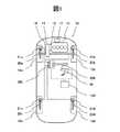
本実施形態の車両10は、図1に示すように、エンジン11と、トルクコンバータ12と、トランスミッション13と、ドライブシャフト14と、車輪15a〜dと、ブレーキペダル16と、ディクスロータ20a〜dと、ブレーキキャリパ21a〜dと、ブレーキ制御装置100と、ブレーキキャリパ21a〜dを動作させるための油圧を発生するマスタ圧発生装置200と、同じくブレーキキャリパ21a〜dを動作させるための油圧を発生するホイール圧発生装置300と、バッテリ17と、を備えている。 As shown in FIG. 1, the
エンジン11は、燃焼室内の混合気を爆発させて、動力を発生させる内燃機関である。爆発により得られるピストンの運動は、コンロッドを介してクランクシャフトの回転運動に変換される。クランクシャフトは、トルクコンバータ12、トランスミッション13、ドライブシャフト14を介して、前輪15a,15bに動力を伝達する。 The
トルクコンバータ12は、エンジン11とトランスミッション13との間に設けられている。このトルクコンバータ12は、油などの作動流体を利用することにより、エンジン11から出力される回転トルクを断続的にトランスミッション13へ伝達するクラッチとしての機能と、その回転トルクを増大させてトランスミッション13へ伝達する機能とを有する。 The
トランスミッション13は、トルクコンバータ12とドライブシャフト14との間に設けられ、例えば、前進5段(第1速〜第5速)、後進1段の各変速段に対応する複数のギアなどを有する。 The
ドライブシャフト14は、トランスミッション13と前輪15a,15bとを連結する回転軸で、エンジン11の回転駆動力を前輪15a及び15bへ伝達する。 The
ブレーキペダル16は、ドライバが車両10を減速させるときに操作するものである。ドライバの踏力は、このブレーキペダル16を介して、第一アクチュエータ装置としてのマスタ圧発生装置200へ伝達される。マスタ圧発生装置200で発生した油圧は、第二アクチュエータとしてのホイール圧発生装置300を介して、ブレーキキャリパ21a〜dへ伝わり、このブレーキキャリパ21a〜dを動作させる。ホイール圧発生装置300は、マスタ圧発生装置200で発生した油圧をそのままブレーキキャリパ21a〜dへ伝えるか、又は、さらに増圧してからブレーキキャリパ21a〜dへ伝える。 The
ブレーキは、ディクスロータ20a〜dとブレーキキャリパ21a〜dとを有して構成される。各ディクスロータ20a〜dは、各車輪15a〜dに対して固定されている、つまり、各車輪15a〜dと一体的に回転する。各ブレーキキャリパ21a〜dは、図示しないが、シリンダ、ピストン、パッド等から構成されている。シリンダ内のピストンは、各圧発生装置200,300からの作動油によって移動し、このピストンに連結されたパッドをディスクロータ20a〜dに押圧する。このパッドがディクスロータ20a〜dを押圧することで、ディクスロータ20a〜dと間に摩擦力を発生される。この摩擦力がブレーキ力となる。 The brake is configured to have
本実施形態では、以上で説明した車両の構成要素のうち、ブレーキペダル16と、ディクスロータ20a〜dと、ブレーキキャリパ21a〜dと、第一アクチュエータ装置としてのマスタ圧発生装置200と、第二アクチュエータ装置としてのホイール圧発生装置300と、ブレーキ制御装置100と、後述のブレーキセンサとで、ブレーキシステムを構成している。 In the present embodiment, among the components of the vehicle described above, the
ブレーキ制御装置100は、図2に示すように、コンピュータであり、各種演算処理を行うCPU110と、外部と信号の受送信を行うインタフェース101と、CPU110が実行する各種プログラムやデータ等が予め記憶されているROM102と、CPU110のワークエリアとなるRAM103と、を有している。 As shown in FIG. 2, the
CPU110は、機能的には、後述の各種センサからの情報に基づいて車両の危険度を推定する危険度推定部111と、危険度推定部111が推定した危険度や各種センサからの情報に基づいてブレーキの目標性能を定める目標性能設定手段112と、危険度推定部111が推定した危険度や各種センサからの情報に基づいて目標ブレーキ力を求める目標ブレーキ力算出部113と、目標ブレーキ力や目標性能に応じてマスタ圧発生装置200及びホイール圧発生装置300のそれぞれの駆動率を求める駆動率算出部114と、外部との間での通信を制御する通信制御部115と、を有している。これらの各機能部111〜115は、いずれも、ROM102に記憶されているプログラムをCPU110が実行することで機能する。 The
各種センサとしては、ブレーキセンサ31と、前輪15a,156bの操舵角を検出する操舵角センサ32と、アクセルペダルのストローク量を検出するアクセルペダルストロークセンサ33と、車両10の車速を検出する車速センサ34と、車両10に発生している実ヨーレートを検出するヨーレートセンサ35と、車両10の前後方向に発生している加速度を検出する前後加速度センサ36と、車両10の横方向に発生している加速度を検出する横加速度センサ37と、各車輪15a〜dの速度を検出する車輪速センサ38と、自車周囲の障害物の位置や路面状態、白線や黄線までの距離を検出する外界認識センサ39とがある。以上の各センサは、いずれも、ブレーキ制御装置100のインタフェース101に接続されている。 The various sensors include a
ブレーキセンサ31は、ドライバの要求ブレーキ力を検出するセンサであり、ブレーキペダル16に連結されているインプットロッド214の変位量を検出するストロークセンサである。なお、ブレーキセンサ31としては、ストロークセンサを複数個組み合わせてもよい。これにより、1つのセンサからの信号が途絶えた場合にも、残りのセンサによってドライバのブレーキ要求が検出、認知されるため、フェールセーフを確保することができる。また、ブレーキセンサ31としては、ブレーキペダル16に加わる踏力を検出する踏力センサや、この踏力センサとストロークセンサとを組み合わせたものであってもよい。 The
外界認識センサ39は、車両外部を撮像する1以上のカメラと、1以上のカメラで得られた画像を処理して画像解析する画像処理装置とを有して構成される。 The
マスタ圧発生装置200は、ブレーキ制御装置100から駆動制御信号を受信するマスタ圧制御器201と、このマスタ圧制御器201により制御されるマスタ圧発生機構210と、を有している。 The master
また、ホイール圧発生装置300は、ブレーキ制御装置100から駆動制御信号を受信するホイール圧制御器301と、このホイール圧制御器301により制御されるホイール圧発生機構310と、を有している。 The wheel
マスタ圧発生機構210は、図3に示すように、戻しバネ収納シリンダ211と、内部が作動油で満たされるマスタシリンダ212と、マスタシリンダ212内に供給する作動油が溜められているリザーバタンク213と、一方の端部がブレーキペダル16に連結され他方の端部がマスタシリンダ212内に臨んでいる第一の加圧手段としてのインプットロッド214と、第二の加圧手段としてのモータ加圧機構220と、を備えている。 As shown in FIG. 3, the master
リザーバタンク213は、図示しない隔壁によって内部が仕切られて、2つの液室を有する。各液室は、マスタシリンダ212内の後述の各液室215,216と接続されている。 The
モータ加圧機構220は、マスタ圧制御器201からの駆動信号で駆動する加圧モータ221と、加圧モータ221の回転トルクを増幅する減速機構230と、回転力を並進力に変える回転−並進変換機構240と、回転−並進変換機構240に接して直線移動する可動部材250と、この可動部材250に押され、マスタシリンダ212内にプライマリ液室215を形成するプライマリピストン251と、マスタシリンダ212内にセカンダリ液室216を形成するセカダリピストン252と、戻しバネ収納シリンダ211内に配され、回転−並進変換機構240に押された可動部材250を元の位置の方向に戻す戻しバネ255と、を有する。 The motor pressure mechanism 220 includes a
減速機構230は、加圧モータ221の回転トルクを自身の減速比分だけ増幅させるものである。減速の方式としては、歯車減速、プーリ減速等が適当であるが、本実施形態では、加圧モータ221の回転軸に取り付けられている駆動側プーリ231と、従動側プーリ232と、両プーリ231,232に掛け渡されているベルト233と、を備えるプーリ減速方式を採っている。なお、加圧モータ221の回転トルクが十分に大きく、減速によるトルクの増幅が必要でない場合には、減速機構230を設けず、加圧モータ221と回転−並進変換機構240とを直結してもよい。これにより、減速機構230の介在に起因して発生する、信頼性、静粛性、搭載性、等に係る諸問題を回避することができる。 The
回転−並進変換機構240は、加圧モータ221の回転動力を並進動力に変換して、可動部材250を介してプライマリピストン251を押圧するものである。変換機構としては、ラックピニオン、ボールネジ等が適当であるが、本実施形態では、従動側プーリ232により回転するボールネジナット241と、このボールネジナット241の回転運動により並進運動するボールネジ軸242と、を備えるボールネジ方式を採っている。 The rotation-
インプットロッド214は、前述したように、一方の端部がブレーキペダル16に連結され、他方の端部がマスタシリンダ212内のプライマリ液室215内に臨んでいる。このため、ブレーキペダル16が踏み込まれ、インプットロッド214が直進移動すると、プライマリ液室215内の作動油圧が上がって、セカンダリピストン252が押圧され、セカンダリ液室216内の作動油圧も上昇する。この結果、プライマリ液室215とホイール圧発生機構310とをつなぐ第一マスタ配管261、及び、セカンダリ液室216とホイール圧発生機構310とをつなぐ第二マスタ配管262に、作動油が供給され、この作動油がホイール圧発生装置300を介して、各ブレーキキャリパ21a〜dへ送られる。このため、モータ加圧機構220が故障等して場合でも、所定のブレーキ力を確保することができる。また、上述したように、ブレーキペダル16が踏み込まれると、プライマリ液室215内の作動油圧が上がるため、この液圧がブレーキペダル反力として作用することになる。したがって、本実施形態の構造を採用することにより、バネ等のブレーキペダル反力を生成する機構が不要となる。これにより、ブレーキシステムの小型・軽量化を図ることができる。 As described above, the
加圧モータ221は、前述したように、マスタ圧制御装器201からの駆動信号に基づいて動作し、所望の回転トルクを発生する。加圧モータ221としては、DCモータ、DCブラシレスモータ、ACモータ等が考えられるが、制御性、静粛性、耐久性の点においては、DCブラシレスモータが望ましい。この加圧モータ221は、位置センサを備えており、この位置センサからの位置信号がマスタ圧制御器201に入力されるように構成されている。これにより、マスタ圧制御器201は、位置センサから位置信号に基づいて加圧モータ221の回転角を算出することができ、さらに、回転−並進変換装置240の並進量、すなわちプライマリピストン251の変位量を算出することができる。 As described above, the
この加圧モータ221の回転トルクは、前述したように、減速機構230により増幅されて、回転−並進変換機構240のボールネジナット241を回転させる。このボールネジナット241の回転によりボールネジ軸242が並進運動し、可動部材250を介してプライマリピストン251が押圧される。 As described above, the rotational torque of the
なお、可動部材250のボールネジ軸242と反対側に、戻しバネ255に一端が接しており、この戻しバネ255の他端が戻しバネ収納シリンダ211の内壁と接触している。すなわち、本実施形態では、ボールネジ軸242の推力と逆方向の力が、可動部材48を介してボールネジ軸242に作用するように構成されている。これにより、加圧モータ221が駆動し、プライマリピストン251が押圧されて、マスタ圧(マスタシリンダ212内の圧力)が加圧されている状態において、この加圧モータ221が故障等により停止し、ボールネジ軸242の戻し制御が不能になった場合でも、戻しバネ255の弾性力によってボールネジ軸242が初期位置に戻され、マスタ圧が概ね零付近まで低下させることができる。このため、加圧モータ211の故障によるブレーキ力の引きずりを回避することができる。 One end of the return spring 255 is in contact with the opposite side of the
プライマリピストン251が押圧されると、プライマリ液室215内の作動油圧が上昇し、これにより、セカンダリピストン252が押圧され、セカンダリ液室216内の作動油圧も上昇する。この結果、プライマリ液室215とホイール圧発生機構310とをつなぐ第一マスタ配管261、及び、セカンダリ液室216とホイール圧発生機構310とをつなぐ第二マスタ配管262に、作動油が供給され、この作動油がホイール圧発生装置300を介して、各ブレーキキャリパ21a〜dへ送られる。すなわち、ドライバの踏力によりインプットロッド214が押圧された場合でも、加圧モータ221の駆動でプライマリピストン251が押圧された場合も、マスタ配管261,262及びホイール圧発生装置300を介して、作動油が各ブレーキキャリパ21a〜dへ送られる。 When the primary piston 251 is pressed, the hydraulic pressure in the
本実施形態では、プライマリピストン251とセカンダリピストン252を用いるタンデム方式を採用している。これは、マスタシリンダ212からの油漏れがあった場合でも、ある程度のマスタ圧を確保するためである。例えば、プライマリピストン251とマスタシリンダ211とで形成されるプライマリ液室215で油漏れがあった場合には、プライマリピストン251により直接セカンダリピストン252を押圧することで、セカンダリ液室216の作動油圧の上昇を確保することができる。 In this embodiment, a tandem method using a primary piston 251 and a
本実施形態では、ドライバのブレーキ操作によるインプットロッド214の変位量に応じて、プライマリピストン251を変位させることで、インプットロッド214によるプライマリ液室215の作動油圧の加圧をさらに増幅することができる。その増幅比(以下、倍力比と称す。)は、インプットロッド214とプライマリピストン251の変位量の比、インプットロッ214とプライマリピストン251の断面積(以下、それぞれ、AIR、APPと称す。)の比等によって決定される。特に、インプットロッド214の変位量と同量だけプライマリピストン251を変位させた場合には、倍力比は(AIR+APP)/AIRに一意に定まる。すなわち,必要な倍力比に基づいて、AIRとAPPを設定し、インプットロッド214の変位量に等しくなるようにプライマリピストン60の変位量を制御することで、常に一定の倍力比を得ることができる。なお、前述の通り、インプットロッド214の変位量は、ブレーキセンサ31によって検出される。また、プライマリピストン251の変位量は、加圧モータ221の位置センサの信号に基づいてマスタ圧制御器201によって算出される。 In the present embodiment, the primary piston 251 is displaced according to the amount of displacement of the
ホイール圧発生機構310は、マスタ圧発生機構210からの作動油の各ブレーキキャリパ21a〜dへの供給を制御するゲートOUT弁310a,310bと、マスタ圧発生機構210からの作動液の後述のポンプへの供給を制御するゲートIN弁311a,311bと、ゲートOUT弁310a,310bを通過した作動油及びポンプからの作動油の各ブレーキキャリパ21a〜dへの供給を制御するIN弁312a〜dと、ブレーキキャリパ11a〜dにかかる作動油圧を減圧制御するOUT弁313a〜dと、マスタ圧発生機構210からゲートIN弁311a,311bを介して送られてきた作動油を昇圧するポンプ314a,314bと、ポンプ314a,314bを駆動するポンプモータ315と、マスタ圧を検出するマスタ圧センサ316と、リザーバータンク317a,317bを備えている。 The wheel
このホイール圧発生機構310としては、アンチロックブレーキ制御用の液圧制御ユニット、車両挙動安定化制御用の液圧制御ユニット、ブレーキバイワイヤ用の液圧制御ユニット等を採用することができる。 As the wheel
このホイール圧発生機構310は、FL輪用ブレーキキャリパ21aとRR輪用ブレーキキャリパ21dへ供給する作動油圧を制御する第一ブレーキ系統と、FR輪用ブレーキキャリパ20bとRL輪用ブレーキキャリパ20cへ供給する作動油圧を制御する第二ブレーキ系とを有する。第一ブレーキ系統には、ゲートOUT弁310aと、ゲートIN弁311aと、IN弁312a,312dと、OUT弁313a,313dと、リザーバータンク317aと、が属している。また、第二ブレーキ系統には、ゲートOUT弁310bと、ゲートIN弁311bと、IN弁312b,312cと、OUT弁313b,313cと、リザーバータンク317bと、が属している。第一ブレーキ系統のゲートOUT弁310a及びゲートIN弁311aには、マスタ圧発生器210のプライマリ液室215に接続されている第一マスタ配管261が接続され、第二ブレーキ系統のゲートOUT弁310b及びゲートIN弁311bには、マスタ圧発生器210のセカンダリ液室216に接続されている第二マスタ配管262が接続されている。 The wheel
このように、二つのブレーキ系統を設けることにより、一方のブレーキ系統が失陥した場合にも、正常なもう一方のブレーキ系統によって、対角2輪分のブレーキ力が確保されるため、車両の挙動が安定に保たれる。 In this manner, by providing two brake systems, even when one brake system fails, the brake force for two diagonal wheels is secured by the other normal brake system. The behavior is kept stable.
ゲートOUT弁310a,310b、ゲートIN弁311a,311b、IN弁312a〜d、OUT弁313a〜dは、いずれもソレノイドを有しており、このソレノイドへの通電によって弁の開閉が行われる電磁式のものである。各弁の開閉制御は、ホール制御器301により制御される。また、本実施形態では、ゲートOUT弁310a,310bとIN弁312a〜dとが、これらの弁への電流断で開状態となり、電流入で閉状態となり、ゲートIN弁311a,311bとOUT弁313a〜dとが、これらの弁への電流断で閉状態となり、電流入で開状態となる。 Each of the gate OUT
ポンプ314a,314bとしては、プランジャポンプ、トロコイドポンプ、ギヤポンプ等が適当であるが、静粛性の点においては、ギヤポンプが望ましい。ポンプモータ315は、ホイール圧制御装器301の駆動信号に基づいて動作し、自身に連結されたポンプ314a,314bを駆動する。ポンプモータ315としては、DCモータ、DCブラシレスモータ、ACモータ等が適当であるが、制御性、静粛性、耐久性の点においては、DCブラシレスモータが望ましい。 As the
マスタ圧センサ316は、マスタ圧発生機構210のセカンダリ液室216に接続されている第二マスタ配管262に接続されている。このマスタ圧センサ316で検出されたマスタ圧は、ホイール圧制御器301に送られる。なお、このマスタ圧センサ316の個数及び設置位置に関しては、制御性、フェールセーフ等を考慮して、適宜決定してよい。 The
次に、ホイール圧発生機構310の動作について説明する。なお、以下では、第一ブレーキ系統のみの動作について説明し、第二ブレーキ系統の動作に関しては、第一ブレーキ系統の動作と同じであるため、その説明を省略する。 Next, the operation of the wheel
まず、マスタ圧発生機構210で昇圧された作動油圧を、さらに昇圧することなく、そのままFL輪用ブレーキキャリパ21aとRR輪用ブレーキキャリパ21dへ送る場合について説明する。 First, a case will be described in which the hydraulic pressure boosted by the master
この場合、ゲートIN弁311a及びOUT弁313a,313dが閉状態で、ゲートOUT弁310a及びIN弁312a,312dが開状態である。 In this case, the gate IN
マスタ圧発生機構210から第一マスタ配管261を経て送られてきた作動油は、ゲートOUT弁310a及びIN弁312a,312dを経て、ブレーキキャリパ21a,21dへ送られる。すなわち、前述したように、マスタ圧発生機構210からの作動油は、ポンプ314aで昇圧されることなく、ブレーキキャリパ21a,21dへ送られる。 The hydraulic oil sent from the master
本実施形態では、前述したように、ゲートOUT弁310a,310bとIN弁312a〜dとが、これらの弁への電流断で開状態となり、ゲートIN弁311a,311bとOUT弁313a〜dとが、これらの弁への電流断で閉状態となる。この電流断のときの各弁の状態は、マスタ圧発生機構210からの作動油がポンプ314aで昇圧されることなく、ブレーキキャリパ21a,21dへそのまま送られるときの各弁の状態と同じである。このため、電源系統が故障して、各弁に電流を供給できなくなっても、マスタ圧発生機構210から作動油を、ブレーキキャリパ21a,21dへ送ることができる。すなわち、ホイール圧発生機構310が故障しても、マスタ圧発生機構210でブレーキキャリパ21a,21dへ送る作動油の圧力を制御することができる。 In this embodiment, as described above, the gate OUT
次に、マスタ圧発生機構210で昇圧された作動油圧を、ポンプ314aでさらに昇圧してから、FL輪用ブレーキキャリパ21aとRR輪用ブレーキキャリパ21dへ送る場合について説明する。 Next, a case will be described in which the hydraulic pressure increased by the master
この場合、ゲートIN弁311a及びIN弁312a,312dが開状態で、ゲートOUT弁310a及びOUT弁313a,313dが閉状態である。 In this case, the gate IN
マスタ圧発生機構210から第一マスタ配管261を経て送られてきた作動油は、ゲートIN弁311aを経て、ポンプ314aに送られ、ここで昇圧される。ポンプ314aで昇圧された作動油は、IN弁312a,312dを経て、ブレーキキャリパ21a,21dへ送られる。なお、マスタ圧発生機構210が故障して、このマスタ圧発生機構210から作動油が送られてこない場合でも、作動油をポンプ314aからブレーキキャリパ21a,21dへ送ることができる。この場合、ゲートIN弁311a及びゲートOUT弁310aは閉状態となる。 The hydraulic oil sent from the master
このように、本実施形態では、マスタ圧発生装置200とホイール圧発生装置300とのうち、一方が欠陥しても、他方の出力を妨げない構成となっている。 Thus, in this embodiment, even if one of the
次に、ブレーキキャリパ21a,21dにかかる作動油圧を減圧する場合について説明する。 Next, a case where the hydraulic pressure applied to the
この場合、OUT弁313a,313dが開状態で、他の弁は、状況に応じて開又は閉状態であるが、IN弁312a,312dは、基本的に閉状態である。 In this case, the
ブレーキキャリパ21a,21d内に溜まっている作動油は、OUT弁313a,313dを経て、リザーバタンク317aに流入する。 The hydraulic oil accumulated in the
なお、リザーバタンク317a内の作動油は、マスタ圧発生機構210からの作動油をポンプ314aで昇圧する際に利用される。 The hydraulic oil in the reservoir tank 317a is used when the hydraulic oil from the master
次に、図4に示すフローチャートに従って、ブレーキ制御装置100の動作について説明する。 Next, the operation of the
ブレーキ制御装置100の通信制御部115は、所定時間毎に、各センサ等から各種車両環境情報を取得し、これをRAM103に格納する(S1,S2)。ここで、所定時間は、ミリセコンド単位である。各センサ等としては、前述したブレーキセンサ31、操舵角センサ32、アクセルペダルストロークセンサ33、車速センサ34、ヨーレートセンサ35、前後加速度センサ36、横加速度センサ37、車輪速センサ38、外界認識センサ39の他に、マスタ圧制御器201、ホイール圧制御器301がある。各センサ31〜39は、基本的に、イグニッションオンの際には、常時、検出値を出力しており、制御部115は、各センサ31〜39からの出力に関して、所定時間毎に受信する。また、マスタ制御器201及びホイール圧制御器301からは、自身が欠陥状態であるか否かを示す信号が出力され、通信制御部115は、これを受信する。なお、各センサ31〜39からの各種車両環境情報は、車両環境情報の変化を把握するために、予め定められた回数分、RAM103に保持される。 The
次に、危険度推定部111が、ステップ2で取得した各種車両環境情報に基づいて、自車に迫る危険度を推定する(S3)。危険度は、急操舵や急加速といった車両の挙動を大きく乱す可能性が高い操作が行われた場合、過剰な車速やヨーレート、横加速度といった車両が車線から逸脱又はスピンする可能性が高い走行状態の場合、路面摩擦係数が低い場合、障害物との距離が短い場合等において、増加する。 Next, the risk
危険度を求める方法としては、例えば、各センサ31〜39による各検出値及び各検出値の変化量に対して、それぞれ所定の重みを掛け合わせ、その後、これらを合計する等で求めることができる。例えば、外界認識センサ39により、前方車両との距離が短く且つ自車との相対速度差が大きい(自車の方が速い)旨が得られ、車速センサ38から自車速度が高い旨が得られ、操舵角センサ32から操舵角が大きい又は急激に増加した旨が得られた場合には、危険度が極めて高くなる。一方、車速センサ38から自車速度が高い旨が得られた場合でも、前方車両との距離が長く自車との相対速度差が小さい(自車の方が速い)又は相対速度差が大きいものの自車の方が遅い旨が得られ、操舵角センサ32から操舵角が小さい旨が得られた場合には、危険度は低くなる。 As a method for determining the degree of risk, for example, each detection value by each of the
また、危険度推定部111は、危険度の他に、危険内容も推定する。例えば、障害物との衝突の可能性のある危険、車線からはみ出す危険、スピンする危険等である。 In addition to the risk level, the risk
次に、目標性能設定部112が、ステップ2で取得した各種車両環境情報、及びステップ3で推定された危険度に基づいて、ブレーキに求める目標性能を設定する(S4)。 Next, the target
目標性能としては、基本的に、危険度が予め定められた閾値以上の場合には、ここではブレーキシステムの応答性能の向上が設定され、危険度が閾値未満の場合には、ここでは、ブレーキシステムの耐久性能の向上が設定される。但し、危険度が閾値未満の場合であっても、例えば、ドライバーによりスポーツ走行モードが設定されている場合や、ドライバーの操作が速い場合には、応答性能の向上が設定される場合もある。 As the target performance, basically, when the risk level is equal to or higher than a predetermined threshold, the improvement of the response performance of the brake system is set here, and when the risk level is lower than the threshold value, the brake performance is set here. An improvement in system durability is set. However, even when the degree of risk is less than the threshold value, for example, when the sport driving mode is set by the driver or when the driver's operation is fast, improvement of response performance may be set.
次に、目標ブレーキ力算出部113が、ステップ2で取得した各種車両環境情報、及びステップ3で推定された危険度に基づいて、時間の推移に伴う目標ブレーキ力の変化を示す目標ブレーキ力特性が求められる(S5)。 Next, the target brake
危険度が閾値以上の場合には、目標ブレーキ力特性は、急峻に目標ブレーキ力が増加する特性が設定される。また、目標ブレーキ力の大きさは、危険内容に応じて定められる。例えば、危険内容が、障害物との衝突の可能性のある危険の場合には、目標ブレーキ力の大きさは、ブレーキシステムで得られる最大値が設定され、路面摩擦抵抗が低くてスピンする危険の場合には、比較的小さな値が設定される。なお、危険度が、前述の閾値よりも高い第二の閾値よりも高くなった場合には、危険内容に関わらず、目標ブレーキ力の特性は急峻に目標ブレーキ力が増加する特性で、目標ブレーキ力の大きさはブレーキシステムで得られる最大値に設定するようにしてもよい。 When the degree of danger is greater than or equal to the threshold, the target brake force characteristic is set such that the target brake force increases sharply. Further, the magnitude of the target brake force is determined according to the danger content. For example, if the danger content is a danger that may cause a collision with an obstacle, the target braking force is set to the maximum value that can be obtained by the brake system, and the road friction resistance is low and the danger of spinning. In this case, a relatively small value is set. When the danger level is higher than the second threshold value, which is higher than the aforementioned threshold value, the target brake force characteristic is a characteristic in which the target brake force increases sharply regardless of the danger content. The magnitude of the force may be set to the maximum value obtained by the brake system.
危険度が閾値未満の場合には、ドライバーの操作に関する情報、つまりブレーキセンサ31からの出力に対応した値が目標ブレーキ力として設定される。但し、例えば、運転者がアクセルペダル及びブレーキペダル16から足を離して運転するオートクルーズモードが設定され、危険度は低いものの、障害物との間の距離を所定以上確保するためにブレーキをかける必要がある場合には、障害物との間の距離、自車速度、操舵角等に応じて定められる。具体的には、障害物との間の距離、自車速度、操舵角等のそれぞれに重みを掛け合わせ、その後、これらを合計することで、目標ブレーキ力を求める。この場合の目標ブレーキ力は、障害物との間の距離が大きいとき小さな値になり、自車速度が大きいときには比較的大きな値になり、操舵角が比較的大きいときには目標ブレーキ力は比較的大きな値になる。 When the degree of risk is less than the threshold value, information related to the driver's operation, that is, a value corresponding to the output from the
なお、一つのブレーキング機会中で、今回の制御時におけるステップ3で推定された危険度と、次回の制御時におけるステップ3で推定された危険度との差が予め定められた値未満の場合には、次回の制御時におけるステップ5では、改めて目標ブレーキ力特性を算出せず、今回の制御時におけるステップ5で算出した目標ブレーキ力特性をそのまま用いる。 In one braking opportunity, the difference between the risk level estimated in
次に、駆動率算出部114が、マスタ圧発生装置200及びホイール圧発生装置300のそれぞれの時間変化に伴う駆動率の変化を示す駆動率特性を求めてから、現時点の各装置200,300の駆動率を求める(S6)。そして、通信制御部115が、各装置200,300に対して、それぞれの現時点の駆動率に応じた駆動率制御信号を出力する(S7)。ここで、駆動率とは、各装置200,300の最大の駆動量に対する実際の駆動量の割合である。 Next, after the drive
駆動率算出部114は、ステップ4で設定された目標性能、及びステップ5で求められた目標ブレーキ力特性に応じて、各装置200,300の駆動率特性を求め、その後、現時点の各装置200,300の駆動率を求める。但し、前回の制御時における危険度と今回の制御時における危険度との差が予め定められた値未満であるため、今回の制御時のステップ5において、新たな目標ブレーキ力特性が求められなかった場合には、今回の制御時のステップ6においても、新たな駆動特性は求められず、前回の制御時のステップ6で求められた駆動率特性が用いられる。そして、前回の制御時のステップ6で求められた駆動率特性から現時点の各装置200,300の駆動率を求める。 The drive
ここで、第一アクチュエータ装置としてのマスタ圧発生装置200、及び第二アクチュエータ装置としてのホイール圧発生装置300の性能について説明する。 Here, the performance of the
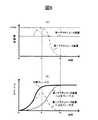
図5は、各アクチュエータ装置200,300に対して、最大の駆動率の駆動制御信号を与えたときの時間経過に伴うブレーキ力の推移を示すものである。 FIG. 5 shows the transition of the braking force with time when each
同図に示すように、第一アクチュエータ装置200は、応答性が低いものの、高いブレーキ力を得ることができる。一方、第二アクチュエータ装置300は、応答性が高いものの、高いブレーキ力を得ることができない。また、同図には示されていないが、第一アクチュエータ装置200は、第二アクチュエータ装置300よりも耐久性が高い。 As shown in the figure, the
そこで、ステップ6では、ステップ4で目標性能として応答性が設定された場合には、応答性の高い第二アクチュエータ装置300を優先的に駆動させるために、この第二アクチュエータ装置300の駆動率を高くし、ステップ4で目標性能として耐久性が設定された場合には、耐久性の高い第一アクチュエータ装置200を優先的に駆動させるために、この第一アクチュエータ装置200の駆動率を高くする。 Therefore, in
具体的に、例えば、ステップ3で危険度として高い値が推定され、ステップ4で目標性能として応答性が設定されたとする。さらに、ステップ5で、図6(b)に示すように、比較的急激に目標ブレーキ力が大ききなり、且つ最大目標ブレーキ力も比較的大きい目標ブレーキ力特性(同図中の太い実線)が求められたとする。 Specifically, for example, it is assumed that a high value is estimated as the risk level in
この場合、駆動率算出部114は、例えば、図6(a)(b)に示すように、第一アクチュエータ装置200の駆動率特性に関して、この第一アクチュエータ装置200の駆動のみで最大目標ブレーキ力が得られる第一アクチュエータ装置200の駆動率を求め、この駆動率を維持する駆動率特性とする。 In this case, for example, as shown in FIGS. 6A and 6B, the drive
また、駆動率算出部114は、第二アクチュエータ装置300の駆動率特性に関しては、現時点t0から第一アクチュエータ装置200によりある程度のブレーキ力を確保できる時刻t1までの期間では、第二アクチュエータ装置300のほぼ最大駆動率とし、時刻t1から第一アクチュエータ装置200のみで最大目標ブレーキ力を確保できる時刻t2までの期間では、徐々に駆動率が低下し、時刻t2では駆動率0となる、駆動率特性とする。In addition, regarding the drive rate characteristics of the
但し、各装置200,300の各時刻の駆動率は、第一アクチュエータ装置200による当該駆動率による駆動で得られるブレーキ力と、第二アクチュエータ装置300による当該駆動率による駆動で得られるブレーキ力とを加算した値が、当該時刻における目標ブレーキ力になるよう、又は、目標ブレーキ力に至らなくても限りなく目標ブレーキ力に近づくように定められる。 However, the driving rate of each
この結果、本実施形態のブレーキシステムでは、ブレーキの高い応答性が要求される場合には、現時点t0から時刻t1までの当初期間において、応答性の高い第二アクチュエータ装置300が高い駆動率で優先的に駆動され、第一アクチュエータ装置200によりある程度のブレーキ力を確保できる時刻t1からは、耐久性の低い第二アクチュエータ装置300が低い駆動率で駆動されるので、極めて高い応答性能を実現しつつ、耐久性も高めることができる。As a result, in the brake system of the present embodiment, when high brake responsiveness is required, the
なお、繰り返すことになるが、現時点t0から時刻t2まで期間は、ブレーキシステムによるブレーキ力の遷移状態で、最終的な最大目標ブレーキ力が得られていないため、この間の各制御時における危険度の変化が小さく、現時点t0で求められた目標ブレーキ力特性及び各装置200,300の駆動率特性は、少なくとも時刻t2までは用いられ、各制御時において、この駆動率特性が示す該当時刻における駆動率が各装置200,300へ出力される。In addition, to repeat, since the final maximum target brake force is not obtained during the period from the current t0 to the time t2 and the brake force is transitioned by the brake system, there is a danger during each control during this period. The target brake force characteristics obtained at the present time t0 and the drive rate characteristics of the
また、ステップ5で、図6(b)に示す目標ブレーキ力特性(同図中の太い実線)よりも、急激に目標ブレーキ力が大きくなる目標ブレーキ力特性が定められた場合、つまり危険度がより高い場合には、図6(a)の矢印が示す細い実線が示すように、第一アクチュエータ装置200に関しても、当初期間、駆動率が最大となる駆動率特性を求めることになる。 In addition, when the target brake force characteristic at which the target brake force suddenly becomes larger than the target brake force characteristic (thick solid line in FIG. 6) shown in FIG. If it is higher, as indicated by the thin solid line indicated by the arrow in FIG. 6A, the driving rate characteristic that maximizes the driving rate in the initial period is also obtained for the
また、第一アクチュエータ装置であるマスタ圧発生装置200は、ブレーキペダル16の操作量に応じた作動油圧を発生させる第一の加圧手段と、モータ加圧機構220で構成される第二の加圧手段とを有しているため、第二の加圧手段の駆動率は、ブレーキ制御装置100から送られてきた駆動率から、第一の加圧手段の現状の駆動率分を差し引いた値となる。 The master
具体的には、マスタ圧発生装置200のマスタ圧制御器201は、マスタ圧制御装置200の駆動率Mをブレーキ制御装置100から受け取ると、この時点での第一加圧手段のみによるマスタ圧発生装置200の駆動率M1をブレーキセンサ31の出力値から求め、マスタ圧制御装置200の駆動率Mから第一加圧手段のみによるマスタ圧発生装置200の駆動率M1を減算して、第二加圧手段のみによるマスタ圧発生装置200の駆動率M2を求める。そして、この駆動率M2を第二加圧手段であるモータ加圧機構220の駆動率m2に換算して、この駆動率m2をモータ加圧機構220に与える。なお、本実施形態では、以上のように、ブレーキ制御装置100は、マスタ圧制御器201へマスタ圧制御装置200の駆動率Mを出力しているが、このブレーキ制御装置100もブレーキセンサ31の出力を取得しているため、このブレーキ制御装置100がマスタ圧発生装置200のモータ加圧機構220の駆動率m2を求め、この駆動率m2をマスタ圧制御器201へ出力するようにしてもよい。 Specifically, when the
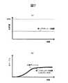
また、例えば、オートクルーズモードのときに、ステップ3で危険度として低い値が推定され、ステップ4で目標性能として耐久性が設定されたとする。さらに、ステップ5で、図7(b)に示すように、緩やかに目標ブレーキ力が大ききなり、且つ最大目標ブレーキ力も小さい目標ブレーキ力特性(同図中の太い実線)が求められたとする。 Also, for example, assume that a low value is estimated as the risk level in
この場合、駆動率算出部114は、例えば、図7(a)に示すように、第一アクチュエータ装置200の駆動率特性に関して、この第一アクチュエータ装置200の駆動のみで最大目標ブレーキ力が得られる第一アクチュエータ装置200の駆動率を求め、この駆動率を維持する駆動率特性とする。また、駆動率算出部114は、第二アクチエータ装置300の駆動率特性に関して、駆動率0を維持する駆動率特性とする。 In this case, for example, as illustrated in FIG. 7A, the drive
この結果、本実施形態のブレーキシステムでは、耐久性のある第一アクチュエータ装置200のみで、目標ブレーキ力特性にほぼ合ったブレーキ力特性を実現できるため、ブレーキシステムの耐久性を高めることができる。 As a result, in the brake system according to the present embodiment, the brake force characteristic that substantially matches the target brake force characteristic can be realized with only the durable
以上の図7に示す例は、オートクルーズモードのときで、図8に示すように、障害物(前方車両)との車間距離d1が比較的大きな場合である。このオートクルーズモードでは、障害物との車間距離が小さくなるにつれ、第一アクチエータ装置200の駆動率として次第に高い値が設定されるのみならず、第二アクチエータ装置200の駆動率も0から次第に高い値が設定される。Example shown in FIG. 7 described above, when the auto-cruise mode, as shown in FIG. 8, the inter-vehicle distance d1 to the obstacle (preceding vehicle) is when relatively large. In this auto-cruise mode, as the inter-vehicle distance from the obstacle becomes smaller, not only the driving rate of the
また、今回の制御時において、二つのアクチュエータ装置200,300とのうち、一方のアクチュエータ装置から欠陥である旨の通知を受けた場合、ステップ6では、他方のアクチュエータ装置の駆動率特性に関して、この他方のアクチュエータ装置のみで、できるかぎり目標ブレーキ力特性を得られるような駆動率特性が定められる。このため、本実施形態では、一方のアクチュエータ装置が欠陥しても、ある程度、目標ブレーキ力特性を得ることができる。 In addition, in this control, when a notification that one of the two
[第二の実施形態]
次に、本発明に係る車両の第二の実施形態について、図9〜図12を用いて説明する。[Second Embodiment]
Next, a second embodiment of the vehicle according to the present invention will be described with reference to FIGS.
本実施形態の車両10aは、第一の実施形態の車両10と同様、図9に示すように、エンジン11と、トルクコンバータ12と、トランスミッション13、ドライブシャフト14と、車輪15a〜dと、ブレーキペダル16と、ディクスロータ20a,20bと、ブレーキキャリパ21a,21bと、ブレーキ制御装置100と、ブレーキキャリパ21a,20bを動作させるための油圧を発生するマスタ圧発生装置200と、同じくブレーキキャリパ21a,20bを動作させるための油圧を発生するホイール圧発生装置300aと、バッテリ17と、を備えている。本実施形態の車両10aは、さらに、後輪15c,15dにブレーキ力を加える回生ブレーキ18を備えている。 As in the
なお、本実施形態では、後輪15c,15d用のブレーキとして、回生ブレーキ18があるため、後輪15c,15dには、ディスクロータ及びブレーキキャリパを設けていないが、これらを設けてもよいことは言うまでもない。 In this embodiment, since the
本実施形態のマスタ圧発生装置200及びホイール圧発生装置300は、それぞれ、第一の実施形態のマスタ圧発生装置200、ホイール圧発生装置300aと基本的に同一である。但し、図10に示すように、本実施形態のホイール圧発生装置300aのホイール圧発生機構310aは、後輪15c,15dにブレーキキャリパが設けられていない関係で、後輪15c,15dのブレーキキャリパに作動油を供給する構成にはなっていない。このため、第一の実施形態のホイール圧発生機構310では、二つのブレーキ系統のそれぞれが二つのブレーキキャリパに作動油を供給する構成になっているが、本実施形態のホイール圧発生機構310aでは、二つのブレーキ系統のそれぞれが一つのブレーキキャリパに作動油を供給する構成になっている。 The
回生ブレーキ18は、左右の後輪15c,15dのそれぞれから伸びる車軸19に接続され、車軸19にブレーキ力を過程で、車軸19の回転により電力を発生して、この電力をバッテリ17に供給するように構成されている。このため、この回生ブレーキ18は、ブレーキとアクチュエータ装置との機能を兼ね備えている。 The
バッテリ17には、バッテリ電圧を検出するための電圧計40が設けられており、この電圧計40は、他のセンサと同様に、ブレーキ制御装置100のインタフェース101と接続されている。 The
次に、本実施形態のブレーキ制御装置100の動作について説明する。 Next, operation | movement of the
本実施形態のブレーキ制御装置100も、図4のフローチャートに示すように、所定時間毎に、ステップ2からステップ7の処理を実行する。 As shown in the flowchart of FIG. 4, the
但し、ステップ2において、ブレーキ制御装置100の通信制御部115は、第一の実施形態で取得した車両環境情報の他に、車両環境情報として、バッテリ17の電圧を検出する電圧計40での検出値を取得すると共に、回生ブレーキ18から自身が欠陥状態であるか否かを示す情報も取得する。 However, in
また、ステップ4において、目標性能設定部113は、ステップ3で求められた危険度が予め定められた閾値未満の場合であって、電圧計40が示す電圧値が予め定められた電圧値未満の場合には、ブレーキシステムの耐久性の向上と共に、省電力が設定される。 In
バッテリ17は、その蓄電量が予め定められた蓄電量未満になると、その電圧値も予め定められた電圧値未満になる。このため、本実施形態では、バッテリ17の蓄電量の替わりに、バッテリ17の電圧値を取得し、この電圧値が予め定められた電圧値未満になると、バッテリ17の蓄電量も予め定められた蓄電量未満になったと仮定して、このときには、目標性能として省電力を設定するようにしている。なお、本実施形態では、バッテリ17の蓄電量をバッテリ17の電圧値から推定する方法を採用しているが、他の方法でバッテリ17の蓄電量を推定する方法を採用してもよい。 When the amount of electricity stored in the
また、ステップ6において、目標駆動率算出部114は、第一アクチュエータ装置200、第二アクチュエータ装置300の駆動率と共に、第三アクチュエータ装置としての回生ブレーキ18の駆動率も求める。 In
例えば、ステップ3で求められた危険度が予め定められた閾値以上で、ステップ4で目標性能として応答性が設定され、ステップ5で、図11に示すように、比較的急激に目標ブレーキ力が大ききなり、且つ最大目標ブレーキ力も比較的大きく、図6(b)に示す目標ブレーキ力特性と同じ目標ブレーキ力特性(同図中の太い実線)が求められたとする。 For example, if the degree of risk obtained in
この場合、駆動率算出部114は、ステップ6において、第二アクチュエータ装置300の駆動率特性に関しては、図6(a)に示す駆動率特性と同じ駆動率特性を求め、第二アクチュエータ装置300によるブレーキ力特性を、図6(b)に示す第二アクチュエータ装置300によるブレーキ力特性と同じブレーキ力特性(図11中の一点破線)とする。また、第一アクチュエータ装置200及び回生ブレーキ18の駆動率特性に関しては、図6(b)に示す第一アクチュエータ装置200によるブレーキ力を、第一アクチュエータ装置200と回生ブレーキ18とで担うように、第一アクチュエータ装置200及び回生ブレーキ18の駆動率特性を定める。すなわち、第二アクチュエータ装置300の駆動率が0になる時刻t2では、第一アクチュエータ装置200によるブレーキ力と回生ブレーキ18によるブレーキ力とを加算した値が最大目標ブレーキ力になるように、第一アクチュエータ装置200及び回生ブレーキ18の駆動率特性を定める。なお、この場合、好ましくは、回生ブレーキ18の駆動率特性は、このブレーキング機会において、第一アクチュエータ装置200及び第二アクチュエータ装置300で消費される電力と、回生ブレーキ18が発生する電力とがほぼ同じになるようにするとよい。In this case, in
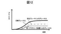
また、例えば、オートクルーズモードのときに、ステップ3で危険度として低い値が推定され、ステップ4で目標性能として耐久性及び省電力が設定され、ステップ5で、図12に示すように、緩やかに目標ブレーキ力が大ききなり、且つ最大目標ブレーキ力も小さく、図7(b)に示す目標ブレーキ力特性と同じ目標ブレーキ力特性(同図中の太い実線)が求められたとする。 Also, for example, in the auto-cruise mode, a low value is estimated as the risk level in
この場合、駆動率算出部114は、例えば、図12に示すように、第二アクチュエータ装置300の駆動率は0で、第一アクチュエータ装置200によるブレーキ力と回生ブレーキ18によるブレーキ力とを加算した値が最大目標ブレーキ力になるように、第一アクチュエータ装置200及び回生ブレーキ18の駆動率特性を定める。なお、この場合、好ましくは、回生ブレーキ18の駆動率特性は、このブレーキング機会において、第一アクチュエータ装置200で消費される電力よりも、回生ブレーキ18が発生する電力の方が大きくなるようにする。但し、電力の発生量を大きくするため、回生ブレーキ18の駆動率をむやみに高くすると、前輪15a,15bと後輪15c,15dとのブレーキバランスが好ましくない状態になるため、ブレーキバランスが許容できる範囲ないで、回生ブレーキ18の駆動率を高くする。 In this case, for example, as shown in FIG. 12, the drive
このように、本実施形態のブレーキシステムでは、ブレーキシステムの応答性及び耐久性の向上を図ることができると共に、ブレーキシステムの省電力化を図ることができる。 As described above, in the brake system according to the present embodiment, the response and durability of the brake system can be improved, and the power consumption of the brake system can be reduced.
[各実施形態の変形例]
次に、以上の各実施形態の各種変形例について説明する。[Modification of each embodiment]
Next, various modifications of the above embodiments will be described.
以上の実施形態は、いずれも、ブレーキペダル16にかかる踏力を第一アクチュエータ装置100へ機械的に伝達するものであるが、図13に示すように、ブレーキペダル16にかかる踏力を第一アクチュエータ装置100bへ電気的に伝達するものであってもよい。具体的には、ブレーキセンサ31の出力に基づいて、ブレーキ制御装置100bが、この踏力相当の駆動を指示する駆動制御信号を第一アクチュエータ装置100bへ送るようにする。すなわち、本発明では、ブレーキペダル16にかかる踏力を第一アクチュエータ装置100へ伝達する手段を限定しない。 In any of the above embodiments, the pedal force applied to the
また、以上の実施形態では、油圧で駆動するブレーキキャリパを採用しているが、本発明は、これに限定されるものではなく、電気信号で駆動するブレーキャリパを採用してもよい。さらに、本発明が適用されるブレーキとしては、以上の各実施形態で述べたディスクブレーキ、回生ブレーキのみならず、例えば、ドラムブレーキ等ではってもよい。 In the above embodiment, a brake caliper that is driven by hydraulic pressure is employed. However, the present invention is not limited to this, and a brake caliper that is driven by an electric signal may be employed. Furthermore, the brake to which the present invention is applied is not limited to the disc brake and the regenerative brake described in the above embodiments, but may be a drum brake, for example.
また、以上の実施形態では、2又は3のアクチュエータ装置を備えているが、本発明は、これに限定されるものではなく、4以上のアクチュエータ装置を備えていてもよい。 In the above embodiment, two or three actuator devices are provided. However, the present invention is not limited to this, and four or more actuator devices may be provided.
また、以上の実施形態では、複数のアクチュエータ装置が互いに異なる性能を有しているが、互いに同性能、つまり同じものであってもよい。この場合、各アクチュエータ装置の駆動率を所定の条件下で変えることで、各アクチュエータの寿命を伸ばすことができるようになる。 In the above embodiment, the plurality of actuator devices have different performances, but may have the same performance, that is, the same. In this case, the life of each actuator can be extended by changing the drive rate of each actuator device under a predetermined condition.
10,10a,10b:車両、15a,15b,15c,15d:車輪、16:ブレーキペダル、17:バッテリ、18:回生ブレーキ、20a,20b,20c,20d:ディスクロータ、21a,21b,21c,21d:ブレーキキャリパ、31:ブレーキセンサ、100,100b:ブレーキ制御装置、110:CPU、111:危険度推定部、112:目標性能設定部、113:目標ブレーキ力算出部、114:駆動率算出部、115:通信制御部、200,200b:マスタ圧発生装置(第一アクチュエータ装置)、201:マスタ圧制御器、210:マスタ圧発生機構、300,300a:ホイール圧発生装置(第二アクチュエータ装置)、301:ホイール圧制御器、310,310a:ホイール圧発生機構10, 10a, 10b: Vehicle, 15a, 15b, 15c, 15d: Wheel, 16: Brake pedal, 17: Battery, 18: Regenerative brake, 20a, 20b, 20c, 20d: Disc rotor, 21a, 21b, 21c, 21d : Brake caliper, 31: brake sensor, 100, 100b: brake control device, 110: CPU, 111: risk level estimation unit, 112: target performance setting unit, 113: target brake force calculation unit, 114: drive rate calculation unit, 115: Communication control unit, 200, 200b: Master pressure generator (first actuator device), 201: Master pressure controller, 210: Master pressure generator, 300, 300a: Wheel pressure generator (second actuator device), 301: Wheel pressure controller, 310, 310a: Wheel pressure generating mechanism
Claims (13)
Translated fromJapanese前記ブレーキに求められる目標性能を設定する目標性能設定手段と、
前記ブレーキによる目標ブレーキ力を求める目標ブレーキ力算出手段と、
前記複数のブレーキにより前記目標ブレーキ力のブレーキ力又は該目標ブレーキ力に近似したブレーキ力を得られ、且つ前記目標性能を実現できる各アクチュエータ装置の駆動率を求める駆動率算出手段と、
前記駆動率算出手段で求められた各アクチュエータ装置の駆動率に応じた駆動制御信号を各アクチュエータ装置に出力する駆動信号出力手段と、
を備えていることを特徴とするブレーキ制御装置。In a brake control device that controls a plurality of actuator devices that drive each braking member of a plurality of brakes,
Target performance setting means for setting target performance required for the brake;
A target brake force calculating means for obtaining a target brake force by the brake;
Drive rate calculation means for obtaining a drive rate of each actuator device capable of obtaining the brake force of the target brake force or a brake force approximate to the target brake force by the plurality of brakes and realizing the target performance;
Drive signal output means for outputting a drive control signal corresponding to the drive rate of each actuator device obtained by the drive rate calculation means to each actuator device;
A brake control device comprising:
前記ブレーキが搭載される車両の環境を検出する検出手段からの情報により、予め定められた手法で該車両の危険度を推定する危険度推定手段を備え、
前記目標ブレーキ力算出手段は、前記検出手段からの情報及び前記危険度推定手段により推定された前記危険度を用いて、予め定められた手法で前記目標ブレーキ力を求め、
前記目標性能設定手段は、前記検出手段からの情報及び前記危険度推定手段により推定された前記危険度に応じて、前記目標性能を定める、
ことを特徴とするブレーキ制御装置。The brake control device according to claim 1, further comprising: a risk estimation unit that estimates a risk of the vehicle by a predetermined method based on information from a detection unit that detects an environment of the vehicle on which the brake is mounted.
The target brake force calculation means obtains the target brake force by a predetermined method using the information from the detection means and the risk estimated by the risk estimation means,
The target performance setting means determines the target performance according to information from the detection means and the risk estimated by the risk estimation means.
A brake control device.
前記駆動率算出手段は、前記危険度推定手段により推定された前記危険度が予め定められた危険度以上であると、全アクチュエータ装置の駆動率を最大にする、
ことを特徴とするブレーキ制御装置。The brake control device according to claim 2,
The drive rate calculation means maximizes the drive rate of all actuator devices when the risk estimated by the risk estimation means is greater than or equal to a predetermined risk.
A brake control device.
前記複数のアクチュエータ装置のうち、少なくとも、一つのアクチュエータ装置は、他のアクチュエータ装置と性能が異なり、
前記駆動率算出手段は、前記複数のアクチュエータ装置のそれぞれの性能に応じて、前記目標性能を実現できる各アクチュエータ装置の駆動率を求める、
ことを特徴とするブレーキ制御装置。In the brake control device according to any one of claims 1 to 3,
Among the plurality of actuator devices, at least one actuator device has different performance from other actuator devices,
The drive rate calculation means determines the drive rate of each actuator device that can achieve the target performance according to the performance of each of the plurality of actuator devices.
A brake control device.
前記検出手段は、前記車両の運転手の操作に関する情報を取得し、
前記目標性能設定手段は、前記検出手段からの前記運転手の操作に関する情報により前記目標性能を定める、
ことを特徴とするブレーキ制御装置。The brake control device according to claim 2,
The detection means acquires information related to the operation of the driver of the vehicle,
The target performance setting means determines the target performance based on information on the driver's operation from the detection means.
A brake control device.
前記検出手段は、前記車両の走行環境に関する情報を取得し、
前記目標性能設定手段は、前記検出手段からの前記車両の走行環境に関する情報により前記目標性能を定める、
ことを特徴とするブレーキ制御装置。The brake control device according to claim 2, wherein the detection means acquires information related to a traveling environment of the vehicle,
The target performance setting means determines the target performance based on information on the traveling environment of the vehicle from the detection means.
A brake control device.
前記目標ブレーキ力算出手段は、時間経過に伴う目標ブレーキ力の変化を示す目標ブレーキ力特性を求め、
前記駆動率算出手段は、各アクチュエータ装置の時間経過に伴う駆動率の変化を示す駆動率特性を求め、
前記駆動信号出力手段は、前記駆動率算出手段で求められた各アクチュエータ装置の駆動率特性が示す現時点の各アクチュエータ装置の駆動率に応じた駆動制御信号を、各アクチュエータ装置に出力する、
ことを特徴とするブレーキ制御装置。In the brake control device according to any one of claims 1 to 6,
The target brake force calculation means obtains a target brake force characteristic indicating a change in the target brake force with time,
The drive rate calculation means obtains a drive rate characteristic indicating a change in drive rate over time of each actuator device,
The drive signal output means outputs a drive control signal corresponding to the current drive rate of each actuator device indicated by the drive rate characteristics of each actuator device obtained by the drive rate calculation means to each actuator device.
A brake control device.
前記ブレーキと、
前記複数のアクチュエータ装置と、
を備えていることを特徴とするブレーキシステム。The brake control device according to any one of claims 1 to 7,
The brake;
The plurality of actuator devices;
A brake system characterized by comprising:
前記複数のアクチュエータ装置は、いずれか一つのアクチュエータ装置が失陥したときでも、失陥した一のアクチュエータ装置を除く他のアクチュエータ装置の駆動によるブレーキ力発生を妨げない構造になっている、
ことを特徴とするブレーキシステム。The brake system according to claim 8, wherein
The plurality of actuator devices have a structure that does not hinder the generation of braking force by driving other actuator devices other than the one actuator device that has failed, even when any one actuator device has failed.
Brake system characterized by that.
前記複数のアクチュエータ装置は、該アクチュエータ装置の失陥を前記ブレーキ制御装置へ通知する失陥通知手段を有し、
前記駆動率算出手段は、前記複数のアクチュエータ装置のうち、いずれかのアクチュエータ装置の前記失陥通知手段から失陥通知を受けた場合には、失陥したアクチュエータ装置の非駆動を補完できるように、残りのアクチュエータ装置の駆動率を求める、
ことを特徴とするブレーキシステム。The brake system according to any one of claims 8 and 9,
The plurality of actuator devices include failure notification means for notifying the brake control device of a failure of the actuator device,
When the drive rate calculation means receives a failure notification from the failure notification means of any one of the plurality of actuator devices, the drive rate calculation means can complement non-drive of the failed actuator device. Find the drive rate of the remaining actuator device
Brake system characterized by that.
前記複数のアクチュエータのうち、少なくとも一つのアクチュエータを成し且つ前記ブレーキを成し、ブレーキ力発生時には電力を発生する回生ブレーキを備え、
前記駆動率算出手段は、前記回生ブレーキが成す前記少なくとも一つのアクチュエータを除く他のアクチュエータの駆動による消費電力が、該回生ブレーキが発生する電力以下になるように、各アクチュエータの駆動率を求める、
ことを特徴とするブレーキシステム。The brake system according to any one of claims 8 to 10,
A regenerative brake that forms at least one of the plurality of actuators and the brake, and generates electric power when a braking force is generated,
The drive rate calculation means obtains the drive rate of each actuator so that the power consumed by driving other actuators excluding the at least one actuator formed by the regenerative brake is less than or equal to the power generated by the regenerative brake.
Brake system characterized by that.
前記車両のバッテリの蓄電量を検出する蓄電量検出手段を備え、
前記目標性能設定手段は、前記蓄電量検出手段により検出された前記バッテリの蓄電量が予め定められた蓄電量未満である場合に、目標性能として省電力を定め、
前記駆動率算出手段は、前記目標性能が前記省電力である場合に、前記回生ブレーキが発生する電力が前記他のアクチュエータの駆動による消費電力より大きくなるように、各アクチュエータの駆動率を求める、
ことを特徴とするブレーキシステム。The brake system according to claim 10, wherein
A storage amount detecting means for detecting a storage amount of the battery of the vehicle;
The target performance setting means determines the power saving as the target performance when the power storage amount of the battery detected by the power storage amount detection means is less than a predetermined power storage amount,
The drive rate calculation means obtains the drive rate of each actuator so that the power generated by the regenerative brake is greater than the power consumed by driving the other actuator when the target performance is the power saving.
Brake system characterized by that.
Priority Applications (3)
| Application Number | Priority Date | Filing Date | Title |
|---|---|---|---|
| JP2008025357AJP2009184467A (en) | 2008-02-05 | 2008-02-05 | BRAKE CONTROL DEVICE, BRAKE SYSTEM HAVING THE SAME, AND VEHICLE |
| US12/363,920US20090195056A1 (en) | 2008-02-05 | 2009-02-02 | Brake Controller, Brake System Provided with the Same, and Vehicle Provided with the Same Brake System |
| EP09001625AEP2088042A1 (en) | 2008-02-05 | 2009-02-05 | Brake controller, brake system provided with the same, and vehicle provided with the same brake system |
Applications Claiming Priority (1)
| Application Number | Priority Date | Filing Date | Title |
|---|---|---|---|
| JP2008025357AJP2009184467A (en) | 2008-02-05 | 2008-02-05 | BRAKE CONTROL DEVICE, BRAKE SYSTEM HAVING THE SAME, AND VEHICLE |
Publications (1)
| Publication Number | Publication Date |
|---|---|
| JP2009184467Atrue JP2009184467A (en) | 2009-08-20 |
Family
ID=40602352
Family Applications (1)
| Application Number | Title | Priority Date | Filing Date |
|---|---|---|---|
| JP2008025357AWithdrawnJP2009184467A (en) | 2008-02-05 | 2008-02-05 | BRAKE CONTROL DEVICE, BRAKE SYSTEM HAVING THE SAME, AND VEHICLE |
Country Status (3)
| Country | Link |
|---|---|
| US (1) | US20090195056A1 (en) |
| EP (1) | EP2088042A1 (en) |
| JP (1) | JP2009184467A (en) |
Cited By (4)
| Publication number | Priority date | Publication date | Assignee | Title |
|---|---|---|---|---|
| WO2014058297A1 (en)* | 2012-10-09 | 2014-04-17 | Chong Woi Joon | An automatic vehicle braking system and a control method |
| JP2015110361A (en)* | 2013-12-06 | 2015-06-18 | 本田技研工業株式会社 | Vehicular brake device |
| KR20150132549A (en)* | 2013-03-20 | 2015-11-25 | 로베르트 보쉬 게엠베하 | Method and system for avoiding a collision in connection with vehicles |
| JP2018020775A (en)* | 2017-09-01 | 2018-02-08 | 日立オートモティブシステムズ株式会社 | Vehicle motion control system |
Families Citing this family (3)
| Publication number | Priority date | Publication date | Assignee | Title |
|---|---|---|---|---|
| US9440632B2 (en)* | 2014-11-05 | 2016-09-13 | Bendix Commercial Vehicle Systems Llc | Method, controller and system for monitoring brake operation |
| CN106184153A (en)* | 2016-08-16 | 2016-12-07 | 北京英创汇智科技有限公司 | A kind of brake fluid system |
| US12017623B2 (en) | 2021-01-27 | 2024-06-25 | Advics Co., Ltd. | Series-connected brake actuators and automatic brake hold method employing same |
Citations (4)
| Publication number | Priority date | Publication date | Assignee | Title |
|---|---|---|---|---|
| JPH10264793A (en)* | 1997-03-27 | 1998-10-06 | Mitsubishi Motors Corp | Braking system with regenerative braking for electric vehicles |
| JP2004189056A (en)* | 2002-12-10 | 2004-07-08 | Nissan Motor Co Ltd | Vehicle braking system |
| WO2006038309A1 (en)* | 2004-10-06 | 2006-04-13 | Hitachi, Ltd. | Electric brake device |
| JP2007050751A (en)* | 2005-08-17 | 2007-03-01 | Advics:Kk | Brake device for vehicle |
Family Cites Families (6)
| Publication number | Priority date | Publication date | Assignee | Title |
|---|---|---|---|---|
| JP2646860B2 (en) | 1991-01-23 | 1997-08-27 | 日産自動車株式会社 | Vehicle braking force control device |
| JP2646861B2 (en) | 1991-01-24 | 1997-08-27 | 日産自動車株式会社 | Vehicle braking force control device |
| US6439674B1 (en)* | 1999-09-01 | 2002-08-27 | Denso Corporation | Vehicle braking apparatus and vehicle braking method |
| US7063393B2 (en)* | 2001-08-22 | 2006-06-20 | Advics Co., Ltd. | Electronic brake system without pump unit |
| EP1448404A1 (en)* | 2001-11-29 | 2004-08-25 | DaimlerChrysler AG | Device for evaluating and/or influencing a motion variable and/or motion behavior of a vehicle |
| JP2007308097A (en) | 2006-05-22 | 2007-11-29 | Toyota Motor Corp | Vehicle and control method thereof |
- 2008
- 2008-02-05JPJP2008025357Apatent/JP2009184467A/ennot_activeWithdrawn
- 2009
- 2009-02-02USUS12/363,920patent/US20090195056A1/ennot_activeAbandoned
- 2009-02-05EPEP09001625Apatent/EP2088042A1/ennot_activeWithdrawn
Patent Citations (4)
| Publication number | Priority date | Publication date | Assignee | Title |
|---|---|---|---|---|
| JPH10264793A (en)* | 1997-03-27 | 1998-10-06 | Mitsubishi Motors Corp | Braking system with regenerative braking for electric vehicles |
| JP2004189056A (en)* | 2002-12-10 | 2004-07-08 | Nissan Motor Co Ltd | Vehicle braking system |
| WO2006038309A1 (en)* | 2004-10-06 | 2006-04-13 | Hitachi, Ltd. | Electric brake device |
| JP2007050751A (en)* | 2005-08-17 | 2007-03-01 | Advics:Kk | Brake device for vehicle |
Cited By (7)
| Publication number | Priority date | Publication date | Assignee | Title |
|---|---|---|---|---|
| WO2014058297A1 (en)* | 2012-10-09 | 2014-04-17 | Chong Woi Joon | An automatic vehicle braking system and a control method |
| KR20150132549A (en)* | 2013-03-20 | 2015-11-25 | 로베르트 보쉬 게엠베하 | Method and system for avoiding a collision in connection with vehicles |
| JP2016515974A (en)* | 2013-03-20 | 2016-06-02 | ローベルト ボッシュ ゲゼルシャフト ミット ベシュレンクテル ハフツング | Method and system for avoiding vehicle-related collisions |
| US9944259B2 (en) | 2013-03-20 | 2018-04-17 | Robert Bosch Gmbh | Method and system for avoiding a vehicle collision |
| KR102164130B1 (en) | 2013-03-20 | 2020-10-12 | 로베르트 보쉬 게엠베하 | Method and system for avoiding a collision in connection with vehicles |
| JP2015110361A (en)* | 2013-12-06 | 2015-06-18 | 本田技研工業株式会社 | Vehicular brake device |
| JP2018020775A (en)* | 2017-09-01 | 2018-02-08 | 日立オートモティブシステムズ株式会社 | Vehicle motion control system |
Also Published As
| Publication number | Publication date |
|---|---|
| US20090195056A1 (en) | 2009-08-06 |
| EP2088042A1 (en) | 2009-08-12 |
Similar Documents
| Publication | Publication Date | Title |
|---|---|---|
| JP5066004B2 (en) | Brake system | |
| JP4762283B2 (en) | Brake control device | |
| US8632136B2 (en) | Brake control system | |
| US9682705B2 (en) | Vehicle having ACC stop and go with braking auto-hold to increase engine autostop availability | |
| KR102187995B1 (en) | Brake control device | |
| EP2828132B1 (en) | Brake device | |
| KR101304208B1 (en) | Method for controlling hydraulic of regenerative brake system for vehicle | |
| CN101519064B (en) | Braking device | |
| JP5411118B2 (en) | Brake device for vehicle | |
| CN107428324B (en) | Method for operating a recuperation brake system of a vehicle and control device for a recuperation brake system of a vehicle | |
| US9132819B2 (en) | Vehicle control apparatus | |
| JP2009184467A (en) | BRAKE CONTROL DEVICE, BRAKE SYSTEM HAVING THE SAME, AND VEHICLE | |
| JP5815183B2 (en) | Brake device for vehicle | |
| JP2009190648A (en) | Brake control device | |
| JP6745739B2 (en) | Brake system | |
| JP2015110361A (en) | Vehicular brake device | |
| JP5024072B2 (en) | Brake control device | |
| JP4499691B2 (en) | Braking control device | |
| JP2004322810A (en) | Vehicle braking system | |
| JP5474132B2 (en) | Brake system | |
| CN117104233A (en) | An anti-rolling control method, system and vehicle | |
| JP4952648B2 (en) | VEHICLE CONTROL DEVICE AND VEHICLE | |
| JP7727837B2 (en) | Vehicle control device, vehicle control method, and vehicle control system | |
| JP5036622B2 (en) | VEHICLE CONTROL DEVICE AND VEHICLE | |
| WO2018139529A1 (en) | Electric brake device |
Legal Events
| Date | Code | Title | Description |
|---|---|---|---|
| A621 | Written request for application examination | Free format text:JAPANESE INTERMEDIATE CODE: A621 Effective date:20091113 | |
| A711 | Notification of change in applicant | Free format text:JAPANESE INTERMEDIATE CODE: A712 Effective date:20100119 | |
| A521 | Written amendment | Free format text:JAPANESE INTERMEDIATE CODE: A821 Effective date:20100119 | |
| A131 | Notification of reasons for refusal | Free format text:JAPANESE INTERMEDIATE CODE: A131 Effective date:20100323 | |
| A977 | Report on retrieval | Free format text:JAPANESE INTERMEDIATE CODE: A971007 Effective date:20100325 | |
| A521 | Written amendment | Free format text:JAPANESE INTERMEDIATE CODE: A523 Effective date:20100524 | |
| A02 | Decision of refusal | Free format text:JAPANESE INTERMEDIATE CODE: A02 Effective date:20101116 | |
| A521 | Written amendment | Free format text:JAPANESE INTERMEDIATE CODE: A523 Effective date:20110202 | |
| A911 | Transfer of reconsideration by examiner before appeal (zenchi) | Free format text:JAPANESE INTERMEDIATE CODE: A911 Effective date:20110207 | |
| A912 | Removal of reconsideration by examiner before appeal (zenchi) | Free format text:JAPANESE INTERMEDIATE CODE: A912 Effective date:20110401 | |
| A761 | Written withdrawal of application | Free format text:JAPANESE INTERMEDIATE CODE: A761 Effective date:20120213 |