JP2009183619A - Endoscope - Google Patents
EndoscopeDownload PDFInfo
- Publication number
- JP2009183619A JP2009183619AJP2008029200AJP2008029200AJP2009183619AJP 2009183619 AJP2009183619 AJP 2009183619AJP 2008029200 AJP2008029200 AJP 2008029200AJP 2008029200 AJP2008029200 AJP 2008029200AJP 2009183619 AJP2009183619 AJP 2009183619A
- Authority
- JP
- Japan
- Prior art keywords
- forceps
- distal end
- endoscope
- tube
- pin
- Prior art date
- Legal status (The legal status is an assumption and is not a legal conclusion. Google has not performed a legal analysis and makes no representation as to the accuracy of the status listed.)
- Pending
Links
- 238000005452bendingMethods0.000claimsabstractdescription40
- 238000003780insertionMethods0.000claimsabstractdescription27
- 230000037431insertionEffects0.000claimsabstractdescription27
- 230000002093peripheral effectEffects0.000claimsdescription22
- 230000003287optical effectEffects0.000description6
- 230000004308accommodationEffects0.000description4
- 239000002184metalSubstances0.000description4
- 230000004048modificationEffects0.000description4
- 238000012986modificationMethods0.000description4
- 239000000853adhesiveSubstances0.000description3
- 230000001070adhesive effectEffects0.000description3
- 238000003384imaging methodMethods0.000description3
- XLYOFNOQVPJJNP-UHFFFAOYSA-NwaterSubstancesOXLYOFNOQVPJJNP-UHFFFAOYSA-N0.000description3
- 238000010586diagramMethods0.000description2
- 229910001220stainless steelInorganic materials0.000description2
- 239000010935stainless steelSubstances0.000description2
- 239000000758substrateSubstances0.000description2
- JOYRKODLDBILNP-UHFFFAOYSA-NEthyl urethaneChemical compoundCCOC(N)=OJOYRKODLDBILNP-UHFFFAOYSA-N0.000description1
- PXGOKWXKJXAPGV-UHFFFAOYSA-NFluorineChemical compoundFFPXGOKWXKJXAPGV-UHFFFAOYSA-N0.000description1
- XUIMIQQOPSSXEZ-UHFFFAOYSA-NSiliconChemical compound[Si]XUIMIQQOPSSXEZ-UHFFFAOYSA-N0.000description1
- 239000000919ceramicSubstances0.000description1
- 239000011248coating agentSubstances0.000description1
- 238000000576coating methodMethods0.000description1
- 229910052731fluorineInorganic materials0.000description1
- 239000011737fluorineSubstances0.000description1
- 239000000314lubricantSubstances0.000description1
- 239000000463materialSubstances0.000description1
- 239000000203mixtureSubstances0.000description1
- -1polytetrafluoroethylenePolymers0.000description1
- 229920001343polytetrafluoroethylenePolymers0.000description1
- 239000004810polytetrafluoroethyleneSubstances0.000description1
- 239000011347resinSubstances0.000description1
- 229920005989resinPolymers0.000description1
- 238000004904shorteningMethods0.000description1
- 229910052710siliconInorganic materials0.000description1
- 239000010703siliconSubstances0.000description1
- 238000004804windingMethods0.000description1
Images


Landscapes
- Instruments For Viewing The Inside Of Hollow Bodies (AREA)
- Endoscopes (AREA)
Abstract
Description
Translated fromJapanese本発明は、先端硬質部に固定された鉗子パイプに接続される鉗子チューブと、先端硬質部に連結されて鉗子チューブを内方に配置する湾曲部とを有する内視鏡に関する。 The present invention relates to an endoscope having a forceps tube connected to a forceps pipe fixed to a distal end hard portion, and a curved portion connected to the distal end hard portion to dispose the forceps tube inward.
図8に従来の内視鏡の挿入部における先端部付近の断面図を示した。
内視鏡の挿入部1の先端には筒状の先端硬質部3が設けられ、先端硬質部3は筒状の先端部本体5を有する。先端部本体5には、鉗子等の処置具を出し入れするための鉗子開口7が形成される。鉗子開口7には金属製の鉗子パイプ9の先端が固定され、鉗子パイプ9の後端は可撓性を有する鉗子チューブ11に接続される。この鉗子チューブ11は、後端が手元操作部(不図示)の鉗子挿入部に連通する。これにより、鉗子挿入部から挿入した鉗子は、先端硬質部3の鉗子開口7から導出可能となる。FIG. 8 shows a cross-sectional view of the vicinity of the distal end portion in the insertion portion of the conventional endoscope.
A cylindrical distal end rigid portion 3 is provided at the distal end of the insertion portion 1 of the endoscope, and the distal end rigid portion 3 has a tubular distal end portion main body 5. A forceps opening 7 for inserting and removing a treatment tool such as forceps is formed in the distal end portion body 5. A distal end of a metal forceps pipe 9 is fixed to the forceps opening 7, and a rear end of the forceps pipe 9 is connected to a
鉗子パイプ9と鉗子チューブ11との接続部は、鉗子パイプ9に鉗子チューブ11を外嵌させてなる。さらに鉗子チューブ11の外側には押さえパイプ(不図示)が被せられることもある。このため、鉗子パイプ9と鉗子チューブ11の接続部は、鉗子パイプ9や鉗子チューブ11よりも太くなる。さらに、接続部の近傍には、固体撮像素子(不図示)や基板13が密集状態で配置される。したがって、先端硬質部3は、この部分で最も太くなるが、挿入時における患者への負担を軽減するには、この部分の細径化が望まれている。 The connection portion between the forceps pipe 9 and the
先端硬質部3の後部は湾曲部15に接続される。湾曲部15は、内部に各種の部材を挿通可能な通路が形成され、遠隔操作によって所定の方向に湾曲可能となる。この湾曲部15には、内部に挿通された各種の部材を保護するために、潰れ方向に強度の高い強度部材として節輪構造体17が採用される。節輪構造体17は、その単位構成要素として、所定の一定幅を有する環状の節輪19が用いられ、前後の節輪19をピン21により順次枢着させ、所定の長さを有した屈曲自在な筒体として構成される。節輪19は、隣接する前後の節輪同士を枢着するために、それぞれ一対の張り出し部19a,19aが形成されている。節輪同士は、この張り出し部19a,19a同士をピン21により枢着して連結される。これによって、前後の節輪19,19が相対的に回動自在に連結され、節輪構造体17の全体が湾曲可能となる。
しかしながら、内視鏡挿入部1の先端硬質部3における先端面は円形状であり、その面内に、大径円形状の鉗子開口7、観察窓23、光照射窓(不図示)の他、送気・送水ノズルが配置されることから、限られた面積で効率的なスペーシングが図るため、大径の鉗子開口7が中心から偏った半径方向外側に配設されることが多い。一方、先端硬質部3に接続される節輪構造体17は、その外径が先端部本体5の外径と略同一に形成されることから、節輪19同士を枢着するピン21が、節輪構造体17の内方へ突出した状態となる。このため、先端部本体5の半径方向外側に偏心配置されて後方へ導出された鉗子チューブ11は、先端硬質部3に最も近い最初の第1ピン21Aに外周面が干渉し易くなり、湾曲動作時の擦れにより、耐久性を低下させる虞があった。これに対し、例えば特許文献1に開示される内視鏡では、鉗子パイプを延長して湾曲させ、鉗子チューブと第1ピンとの干渉を回避する構造を採用しているが、擦れ回避のために屈曲部を延長させた長尺の鉗子パイプを用いると、先端硬質部が長くなることから、内視鏡の湾曲部15における湾曲半径を小さくできず、湾曲方向の可動範囲が狭くなった。
本発明は上記状況に鑑みてなされたもので、長尺の鉗子パイプを用いることなく、鉗子チューブと第1ピンの干渉が回避される内視鏡を提供し、もって、湾曲半径を小さく維持しつつ、鉗子チューブの耐久性向上を図ることを目的とする。However, the distal end surface of the distal end rigid portion 3 of the endoscope insertion portion 1 is circular, and in addition to the large-diameter circular forceps opening 7, an
The present invention has been made in view of the above circumstances, and provides an endoscope in which interference between the forceps tube and the first pin is avoided without using a long forceps pipe, and thus the curvature radius is kept small. Meanwhile, it is an object to improve the durability of the forceps tube.
本発明に係る上記目的は、下記構成により達成される。
(1) 挿入部の先端に設けられた筒状の先端硬質部と、該先端硬質部に形成される鉗子開口に固定された鉗子パイプと、該鉗子パイプに先端部が接続され可撓性を有した鉗子チューブと、前記先端硬質部に連結され多数の節輪同士を互いにピンによって枢着して湾曲自在となり該鉗子チューブを内方に配置した湾曲部と、を備える内視鏡であって、
前記湾曲部の内面から突出するピンの高さよりも厚い嵩上部材が、前記先端硬質部に最も近い第1ピンより前記先端硬質部側の前記鉗子チューブの外面に固着された内視鏡。The above object of the present invention is achieved by the following configuration.
(1) A cylindrical distal end hard portion provided at the distal end of the insertion portion, a forceps pipe fixed to a forceps opening formed in the distal end hard portion, and a distal end portion connected to the forceps pipe for flexibility. An endoscope comprising: a forceps tube having a bending portion in which a plurality of node rings connected to the distal end rigid portion are pivotally attached to each other by a pin and can be freely bent; and the forceps tube is disposed inward. ,
An endoscope in which a bulky member thicker than the height of a pin protruding from the inner surface of the curved portion is fixed to the outer surface of the forceps tube on the distal end hard portion side than the first pin closest to the distal end hard portion.
この内視鏡によれば、鉗子チューブの外面に嵩上部材が固着され、鉗子チューブが嵩上部材の厚み分、湾曲部の内面から離間して、第1ピンと干渉しなくなる。また、嵩上部材が固着されることで、短尺のままの鉗子パイプに鉗子チューブが接続され、鉗子チューブと第1ピンとの擦れが防止可能となるので、擦れ回避のために屈曲部を延長させた長尺の鉗子パイプを用いる必要がなくなる。 According to this endoscope, the bulky member is fixed to the outer surface of the forceps tube, and the forceps tube is separated from the inner surface of the bending portion by the thickness of the bulky member and does not interfere with the first pin. Further, since the bulky member is fixed, the forceps tube is connected to the forceps pipe having a short length, and the friction between the forceps tube and the first pin can be prevented. Therefore, the bent portion is extended to avoid rubbing. There is no need to use a long forceps pipe.
(2) (1)記載の内視鏡であって、前記嵩上げ部材が、内周面の閉じた環状に形成されている内視鏡。(2) The endoscope according to (1), wherein the raising member is formed in an annular shape having an inner peripheral surface closed.
この内視鏡によれば、環状の嵩上部材が鉗子チューブに外挿されることで、嵩上部材の鉗子チューブからの脱落が確実に防止される。また、環状の嵩上部材の内周面が鉗子チューブの円周方向に固着することで、高い固定強度が得られるとともに、この部分における鉗子チューブの潰れ強度も高められる。 According to this endoscope, the annular lifting member is extrapolated to the forceps tube, so that the lifting member is reliably prevented from falling off the forceps tube. In addition, since the inner peripheral surface of the annular lifting member is fixed in the circumferential direction of the forceps tube, a high fixing strength is obtained, and the crushing strength of the forceps tube in this portion is also increased.
(3) (1)記載の内視鏡であって、前記嵩上げ部材が、前記湾曲部の内面と対向する面の反対側に、環状内周面を開放する分断部を有している内視鏡。(3) The endoscope according to (1), wherein the raising member has a dividing portion that opens an annular inner peripheral surface on a side opposite to a surface facing the inner surface of the bending portion. mirror.
この内視鏡によれば、分断部により嵩上部材が除去される分、嵩上部材と他の部材との干渉が回避可能となり、収容密度が高められて、挿入部の小径化が可能となる。また、分断部から鉗子チューブが半径方向に嵌着可能となり、嵩上部材の取付作業性が向上する。 According to this endoscope, since the bulky member is removed by the dividing portion, interference between the bulky member and other members can be avoided, the accommodation density is increased, and the diameter of the insertion portion can be reduced. Become. Further, the forceps tube can be fitted in the radial direction from the dividing portion, and the workability of attaching the bulky member is improved.
(4) (2)記載の内視鏡であって、前記嵩上げ部材の外周面が該嵩上部材の軸線に平行に形成され、かつ内周面が前記嵩上部材の軸線に傾斜して形成された内視鏡。(4) The endoscope according to (2), wherein an outer peripheral surface of the raising member is formed in parallel with an axis of the raising member, and an inner peripheral surface is inclined with respect to the axis of the raising member. Endoscope.
この内視鏡によれば、挿入部の半径方向外側に位置する鉗子パイプから、第1ピンを回避する位置である挿入部の半径方向内側に配置される鉗子チューブをつなぐ鉗子チューブ軸線の傾斜角度に、嵩上げ部材の内周面が沿うように配置可能となり、鉗子チューブに段部が生じ難くなる。これにより、第1ピンとの干渉回避部において鉗子チューブがスムーズに曲がり、鉗子の良好な挿入性が確保される。 According to this endoscope, the inclination angle of the forceps tube axis that connects the forceps tube arranged on the radially inner side of the insertion portion, which is the position avoiding the first pin, from the forceps pipe located on the radially outer side of the insertion portion. In addition, it is possible to arrange the raising member so that the inner peripheral surface thereof is along, and it is difficult to form a step in the forceps tube. As a result, the forceps tube bends smoothly at the interference avoidance portion with the first pin, and good insertability of the forceps is ensured.
(5) (2)記載の内視鏡であって、環状の前記嵩上げ部材が、前記湾曲部の内面と対向する面の反対側に、前記嵩上部材の軸線方向の端から内側に切り欠いた切欠部を有している内視鏡。(5) The endoscope according to (2), wherein the annular raising member is notched inward from an end in an axial direction of the raising member on a side opposite to a surface facing the inner surface of the bending portion. An endoscope having a notch.
この内視鏡によれば、嵩上げ部材が内周面の閉じた環状形状を維持することで、脱落の確実な防止、高い固定強度、鉗子チューブの高い潰れ強度が得られるのに加え、切欠部により嵩上部材が除去される分、嵩上部材と他の部材との干渉が回避され、収容密度が高められて、挿入部の小径化が可能となる。 According to this endoscope, the raising member maintains an annular shape with a closed inner peripheral surface, so that it is possible to surely prevent dropping, high fixing strength, high crushing strength of the forceps tube, and a notch As a result of the removal of the bulky member, interference between the bulky member and other members is avoided, the accommodation density is increased, and the insertion portion can be reduced in diameter.
本発明に係る内視鏡によれば、先端硬質部に連結され多数の節輪同士を互いにピンによって枢着して鉗子チューブを内方に配置する湾曲部を備えた内視鏡において、湾曲部の内面から突出するピンの高さよりも厚い嵩上部材を、先端硬質部に最も近い第1ピンより先端硬質部側の鉗子チューブの外面に固着したので、鉗子チューブが嵩上部材の厚み分、湾曲部の内面から離間し、第1ピンとの干渉を防止して、鉗子チューブの耐久性を向上させることができる。また、短尺の鉗子パイプのまま鉗子チューブを接続して、鉗子チューブと第1ピンとの擦れを防止できるので、擦れ回避のために屈曲部を延長させた長尺の鉗子パイプを用いる必要がなく、先端硬質部を短くでき、湾曲半径をより小さくして、湾曲方向の可動範囲の広い内視鏡を得ることができる。 According to the endoscope according to the present invention, in the endoscope having a bending portion that is connected to the distal end hard portion and pivotally attaches a large number of node rings to each other by pins, and the forceps tube is disposed inward, the bending portion Since the bulky member thicker than the height of the pin protruding from the inner surface of the pin is fixed to the outer surface of the forceps tube on the distal end hard portion side than the first pin closest to the distal end hard portion, the forceps tube is equal to the thickness of the bulky member, It is possible to improve the durability of the forceps tube by separating from the inner surface of the bending portion and preventing interference with the first pin. Also, since the forceps tube can be connected with the short forceps pipe to prevent rubbing between the forceps tube and the first pin, it is not necessary to use a long forceps pipe with an extended bent portion to avoid rubbing, An endoscope having a wide movable range in the bending direction can be obtained by shortening the distal end hard portion and making the bending radius smaller.
以下、本発明に係る内視鏡の好適な実施の形態について、図面を参照して詳細に説明する。
図1は本発明に係る内視鏡の全体構成を表す平面図である。
内視鏡100は、手元操作部31と、この手元操作部31に接続された挿入部33を有している。挿入部33は、軟性部35、湾曲部37、先端硬質部39から構成されており、湾曲部37は、手元操作部31に設けられた湾曲操作用ノブ41,42を回動させることにより遠隔的に湾曲操作され、先端硬質部39が所望の方向に向けられる。Hereinafter, preferred embodiments of an endoscope according to the present invention will be described in detail with reference to the drawings.
FIG. 1 is a plan view showing the overall configuration of an endoscope according to the present invention.
The
手元操作部31には、鉗子等の処置具が挿入される鉗子挿入部43が設けられるとともに、送気・送水ボタン45、吸引ボタン47、シャッターボタン49、および機能切替ボタン51が並設される。また、手元操作部31にはユニバーサルケーブル53が接続され、このユニバーサルケーブル53の先端には光源装置(不図示)に着脱可能に接続される光源コネクタが装着されている。 The
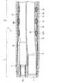
図2は内視鏡の先端硬質部および湾曲部の断面図である。
先端硬質部39および湾曲部37の外周は被覆部材であるアングルゴム55により被覆されている。先端硬質部39は、セラミックスやステンレス等の硬質部材からなる先端部本体57と、先端部本体57と嵌合固定された金属製外筒である先端スリーブ59とを有する。先端部本体57は、体内を観察するための後述の観察光学系や処置具導出用の開口を備える。先端部本体57の先端面にはこれら観察光学系や処置具導出用開口と連通する複数の窓部を有する樹脂製のキャップ部材61が装着される。FIG. 2 is a cross-sectional view of the distal end hard portion and the bending portion of the endoscope.
The outer periphery of the distal end
先端スリーブ59は、先端硬質部39の外殻を形成する円筒状の部材である。先端スリーブ59の先端は先端部本体57に嵌合固定される一方、先端スリーブ59の基端は湾曲部37に接続されている。先端スリーブ59の外周は上記アングルゴム55で被覆される。 The
アングルゴム55は,先端部本体57および湾曲部37の外周を被覆する被覆部材であり、外皮チューブとして機能する。アングルゴム55は、柔軟性を有する絶縁性弾性部材からなる。アングルゴム55は、本実施の形態において例えばフッ素を材質としたゴムにより形成される。アングルゴム55の先端は、先端スリーブ59を越えてキャップ部材61の後端に当接した状態で、外周に糸63を堅く巻回して接着剤65を塗布することにより先端部本体57の縮径部67に固着される。接着剤65としては例えばシリコン系の接着シール材を用いることができる。アングルゴム55の基端は、湾曲部37の基端に固着される。このように両端が固着されて、アングルゴム55内は気密に保持されている。 The
先端部本体57に穿設された観察光学系の開口には複数の対物レンズ69が配設されている。この対物レンズ69の後方には、撮像素子ブロック71が配置され、図示は省略するが基板上に実装された固体撮像素子(CCD)が設けられている。このCCDの受光面に、対物レンズ69から取り込まれた観察像が結像される。この観察像は、CCDによって電気信号に変換されて、不図示の信号ケーブルを介してユニバーサルケーブル53の電気コネクタからプロセッサ(不図示)に出力される。プロセッサに出力された電気信号は、信号処理回路によって映像信号に変換された後、モニタ(不図示)に出力される。 A plurality of
また、先端部本体57には、その軸方向に鉗子開口73が形成され、この鉗子開口73に、金属性の鉗子パイプ75が嵌入されて固定される。鉗子パイプ75は、後端部(すなわち、図2の右側端部)に鉗子チューブ77が接続される。鉗子チューブ77は、例えば、ポリテトラフルオロエチレン製のチューブを被覆ネットで被覆し、これをウレタン等でコーティングして構成される。鉗子チューブ77は、挿入部33に挿通され、手元操作部31(図1参照)の鉗子挿入部43に連通される。これにより、鉗子挿入部43から挿入した鉗子等の処置具を、鉗子開口73に導くことができる。なお、図2中、79はキャップ部材61に穿設された観察光学系窓部、81は鉗子窓部を示す。 Further, a
鉗子パイプ75と鉗子チューブ77との接続部は、鉗子パイプ75の後端部に鉗子チューブ77を外嵌させた構造となる。また、接続部において、鉗子チューブ77の外側に、さらにステンレス製の押さえパイプ(不図示)を嵌め込むことによって締着されてもよい。 The connecting portion between the
湾曲部37の内部には、鉗子チューブ77の他、図示は省略するが、ライトガイド、信号ケーブル類等が挿通されている。したがって、外力の作用により潰れない構造となっていなければならない。しかも、上記したように、先端硬質部39の方向を制御するために、少なくとも上下2方向、好ましくは上下および左右の4方向に湾曲操作できる構成となっていなければならない。このために、湾曲部37の外側は3層構造の筒体で構成される。そのうち、最も内層は節輪構造体85であって、この節輪構造体85にはネット(不図示)が被着される。さらに、最外層として、弾性チューブからなる上記のアングルゴム55が外皮層として設けられている。そして、これらの構造のうち、節輪構造体85が強度部材である。 In addition to the
図3は図1に示した湾曲部に内設される節輪構造体の斜視図である。
節輪構造体85は、所定数の節輪(アングルリング)87を用いる。節輪87は、隣接する前後の節輪87同士を枢着するために、それぞれ一対の張り出し部87a,87aが形成されている。節輪同士は、この張り出し部87a,87a同士をピン(枢着ピン)89により連結することによって、前後の節輪87,87が枢着ピン89を中心として相対回動できるようになっている。FIG. 3 is a perspective view of a node ring structure provided in the bending portion shown in FIG.
The
節輪構造体85の外周とアングルゴム55の内周との間にはネット(不図示)が介在している。ネットは金属等の線材の編組からなる筒状のネット部材である。節輪構造体85は、外周が潤滑剤を介してネットで被覆され、そのネットの外周がさらにアングルゴム55で被覆されている。また、ネットの先端は、先端スリーブ59の基端を被覆し、先端スリーブ59に固着される。 A net (not shown) is interposed between the outer periphery of the
図3に例示した節輪構造体85は、前後の節輪87,87が2箇所で枢着されているもので、2方向(左右あるいは上下)に回動するものであるが、それに限定されない。節輪構造体85は、左右の2箇所が枢着されていると上下に回動し、上下の2箇所が枢着されていると左右に回動することになる。したがって、所定数の節輪87を左右、上下の順に順次連結した構成にすれば、節輪構造体85の全体を上下及び左右に湾曲させることができる。 The
節輪構造体85は、その先端側に連結リング91が連結されており、連結リング91はその基端側が、先端硬質部39に最も近い第1ピン(第1枢着ピン)89Aにより先端の節輪87と連結される。連結リング91の先端側は先端硬質部39の先端スリーブ59に嵌合固定される。 The
節輪87の内部には,複数の操作ワイヤ(不図示)が内周面の軸方向に沿って配設されている。操作ワイヤの先端は,先端スリーブ59に固定され、操作ワイヤの基端は湾曲操作用ノブ41,42で回動されるプーリ(不図示)に接続されている。湾曲操作用ノブ41,42を操作してプーリを回動すると、操作ワイヤが牽引され、湾曲部37が所望の方向に湾曲される。これによって、挿入部33を体腔内に挿入する際には、その先端硬質部39が目的とする方向に向くように制御されたり、また観察光学系の観察視野を変えたりすることができるようになる。 Inside the
上記のように、内視鏡100は、挿入部33の先端に設けられた筒状の先端硬質部39と、この先端硬質部39に形成される鉗子開口73に固定された鉗子パイプ75と、鉗子パイプ75に先端部が接続され可撓性を有した鉗子チューブ77と、先端硬質部39に連結され多数の節輪87同士を互いにピンによって枢着して湾曲自在となり鉗子チューブ77を内方に配置した湾曲部37とを備える。 As described above, the
先端硬質部39の先端面は、前述したように、円形状の面内に、大径円形状の鉗子窓部81、観察光学系窓部79、光照射窓(不図示)の他、送気・送水ノズルが配置されることから、限られた面積で効率的なスペーシングが求められる。そのため、大径の鉗子開口73が先端スリーブ59の中心から半径方向外側に偏って配設されている。また、先端スリーブ59に接続される節輪構造体85は、その外径が先端スリーブ59の外径と略同一に形成れることから、節輪87同士を枢着する枢着ピン89が、節輪構造体85の内方へ突出した状態となっている。 As described above, the distal end surface of the distal end
図4は第1ピンの近傍に配置される部材の位置関係を表した拡大断面図である。
本発明に係る内視鏡の構成では、先端硬質部39に最も近い第1枢着ピン89Aより先端硬質部39側の鉗子チューブ77の外面77aに、湾曲部37(図示例では連結リング91)の内面37aから突出するピン頂部(第1枢着ピン頂部)93の高さH2よりも厚みH1の厚い嵩上部材95が固着されている。FIG. 4 is an enlarged cross-sectional view showing the positional relationship of members disposed in the vicinity of the first pin.
In the configuration of the endoscope according to the present invention, the bending portion 37 (the connecting
嵩上部材95は、本実施形態においては図2に示すように、内周面95aの閉じた環状(リング状)に形成されている。環状の嵩上部材95が鉗子チューブ77に外挿されることで、嵩上部材95の鉗子チューブ77からの脱落が確実に防止されるようになっている。また、環状の嵩上部材95の内周面95aが鉗子チューブ77の円周方向に固着することで、高い固定強度が得られるとともに、この部分における鉗子チューブ77の潰れ強度も高められている。 In the present embodiment, the lifting
このように、内視鏡100では、鉗子チューブ77の外面77aに嵩上部材95が固着され、鉗子チューブ77が嵩上部材95の厚みH1分、湾曲部37の内面37aから離間して、第1枢着ピン89Aと干渉しなくなる。また、嵩上部材95が固着されることで、短尺のままの鉗子パイプ75に鉗子チューブ77が接続され、鉗子チューブ77と第1枢着ピン89Aとの擦れが防止可能となるので、擦れ回避のために、屈曲部を延長させた長尺の鉗子パイプを用いる必要がなくなる。なお、嵩上部材95は、先端硬質部39に最も近接する第1枢着ピン89Aの先端側に配設するのみでよく、他の位置では不要となる。Thus, in the
したがって、上記構成の内視鏡100によれば、先端硬質部39に連結され多数の節輪87同士を互いにピンによって枢着して鉗子チューブ77を内方に配置する湾曲部37を備え、この湾曲部37の内面37aから突出する第1枢着ピン頂部93の高さH2よりも厚みH1の厚い嵩上部材95を、先端硬質部39に最も近い第1枢着ピン89Aより先端硬質部側の鉗子チューブ77の外面77aに固着している。これにより、鉗子チューブ77が嵩上部材95の厚みH1分、湾曲部37の内面37aから離間され、第1枢着ピン89Aとの干渉を防止して、鉗子チューブ77の耐久性を向上させることができる。Therefore, according to the
また、短尺の鉗子パイプ75のまま鉗子チューブ77を接続して、鉗子チューブ77と第1枢着ピン89Aとの擦れを防止できるので、擦れ回避のために屈曲部を延長させた長尺の鉗子パイプを用いる必要がなく、先端硬質部39を短くできる。これにより、湾曲半径をより小さくして、湾曲方向の可動範囲の広い内視鏡の構成にできる。 Further, the
なお、本発明に係る内視鏡は、上記した実施の形態による構成に限定されることなく、適宜な変更が可能である。以下に本発明に係る内視鏡の変形例を説明する。
図5は分断部を有する嵩上部材の固着された鉗子チューブの斜視を(a)、そのA−A矢視を(b)に表した嵩上部材の変形例に係る構成図である。
内視鏡は、嵩上部材95Aが、湾曲部37の内面37a(図4参照)と対向する面95bの反対側に、環状内周面95aを開放する分断部101を有したものであってもよい。Note that the endoscope according to the present invention is not limited to the configuration according to the above-described embodiment, and can be appropriately changed. Hereinafter, modified examples of the endoscope according to the present invention will be described.
FIG. 5 is a configuration diagram according to a modification example of the bulking member, in which a perspective view of the forceps tube to which the bulking member having the dividing portion is fixed is shown in (a), and its AA arrow is shown in (b).
In the endoscope, the bulking
この変形例によれば、分断部101により嵩上部材95Aの一部が除去される分、嵩上部材95Aと他の部材との干渉が回避でき、収容密度をより高められ、挿入部33(先端硬質部39、湾曲部37)の一層の小径化が可能となる。また、分断部101から鉗子チューブ77が半径方向に嵌着可能となり、嵩上部材95Aの取付作業性が向上する。 According to this modification, as a part of the
図6は内周面の傾斜した嵩上部材の固着された鉗子チューブの斜視図である。
また、本発明に係る内視鏡は、嵩上部材95Bの外周面95dが、この嵩上部材95Bの軸線103に平行に形成され、かつ内周面95aが嵩上部材95Bの軸線103に傾斜して形成されたものであってもよい。FIG. 6 is a perspective view of a forceps tube to which a bulky member having an inclined inner peripheral surface is fixed.
In the endoscope according to the present invention, the outer
この変形例によれば、挿入部33の半径方向外側に偏心して配置される鉗子パイプ75(図2参照)から、第1枢着ピン89Aを回避する位置である挿入部33の半径方向内側に配置される鉗子チューブ77をつなぐ鉗子チューブ77の軸線105の傾斜角度に、嵩上部材95Bの内周面95aが沿うように配置可能となる。これにより、鉗子チューブ77に段部が生じ難くなり、第1枢着ピン89Aとの干渉回避部において鉗子チューブ77がスムーズに曲がり、鉗子の良好な挿入性が確保される。 According to this modification, from the forceps pipe 75 (see FIG. 2) that is eccentrically arranged on the outer side in the radial direction of the
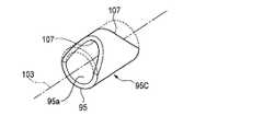
図7は切欠部を有する嵩上部材の斜視図である。
さらに、本発明に係る内視鏡は、環状の嵩上部材95Cが、湾曲部37の内面37a(図4参照)と対向する面95bの反対側に、嵩上部材95Cの軸線103の方向の端から内側に切り欠いた切欠部107を有したものであってもよい。FIG. 7 is a perspective view of a bulky member having a notch.
Furthermore, in the endoscope according to the present invention, the annular raised
この変形例によれば、嵩上部材95Cが内周面95aの閉じた環状形状を維持することで、脱落の確実な防止、高い固定強度、鉗子チューブ77の高い潰れ強度が得られるのに加え、切欠部107にて嵩上部材95Cの一部分が除去され、嵩上部材95Cと他の部材との干渉が回避される。これによっても、収容密度が高められて、挿入部33(先端硬質部39、湾曲部37)の小径化が可能となる。 According to this modified example, the bulking
33 挿入部
37 湾曲部
37a 湾曲部の内面
39 先端硬質部
73 鉗子開口
75 鉗子パイプ
77 鉗子チューブ
77a 鉗子チューブの外面
87 節輪
89 枢着ピン
89A 第1枢着ピン
93 第1枢着ピン頂部
95 嵩上部材
95a 嵩上部材の内周面
95d 嵩上げ部材の外周面
101 分断部
100 内視鏡
103 嵩上部材の軸線
107 切欠部
H2 ピンの高さ33
Claims (5)
Translated fromJapanese前記湾曲部の内面から突出するピンの高さよりも厚い嵩上部材が、前記先端硬質部に最も近い第1ピンより前記先端硬質部側の前記鉗子チューブの外面に固着された内視鏡。A cylindrical distal end hard portion provided at the distal end of the insertion portion, a forceps pipe fixed to a forceps opening formed in the distal end hard portion, and a forceps having a distal end connected to the forceps pipe and having flexibility An endoscope comprising a tube and a bending portion connected to the distal end hard portion and pivotally attached to each other by pins to bend and the forceps tube is disposed inward.
An endoscope in which a bulky member thicker than the height of a pin protruding from the inner surface of the curved portion is fixed to the outer surface of the forceps tube on the distal end hard portion side than the first pin closest to the distal end hard portion.
前記嵩上げ部材が、内周面の閉じた環状に形成されている内視鏡。The endoscope according to claim 1, wherein
An endoscope in which the raising member is formed in an annular shape with an inner peripheral surface closed.
前記嵩上げ部材が、前記湾曲部の内面と対向する面の反対側に、環状内周面を開放する分断部を有している内視鏡。The endoscope according to claim 1, wherein
An endoscope in which the raising member has a dividing portion that opens an annular inner peripheral surface on a side opposite to a surface facing the inner surface of the curved portion.
前記嵩上げ部材の外周面が該嵩上部材の軸線に平行に形成され、かつ内周面が前記嵩上部材の軸線に傾斜して形成された内視鏡。The endoscope according to claim 2, wherein
An endoscope in which an outer peripheral surface of the raising member is formed in parallel to an axis of the raising member, and an inner peripheral surface is inclined to the axis of the raising member.
環状の前記嵩上げ部材が、前記湾曲部の内面と対向する面の反対側に、前記嵩上げ部材の軸線方向の端から内側に切り欠いた切欠部を有している請求項2記載の内視鏡。The endoscope according to claim 2, wherein
The endoscope according to claim 2, wherein the annular raising member has a notch that is notched inward from an end in the axial direction of the raising member on the opposite side of the surface facing the inner surface of the curved portion. .
Priority Applications (1)
| Application Number | Priority Date | Filing Date | Title |
|---|---|---|---|
| JP2008029200AJP2009183619A (en) | 2008-02-08 | 2008-02-08 | Endoscope |
Applications Claiming Priority (1)
| Application Number | Priority Date | Filing Date | Title |
|---|---|---|---|
| JP2008029200AJP2009183619A (en) | 2008-02-08 | 2008-02-08 | Endoscope |
Publications (1)
| Publication Number | Publication Date |
|---|---|
| JP2009183619Atrue JP2009183619A (en) | 2009-08-20 |
Family
ID=41067527
Family Applications (1)
| Application Number | Title | Priority Date | Filing Date |
|---|---|---|---|
| JP2008029200APendingJP2009183619A (en) | 2008-02-08 | 2008-02-08 | Endoscope |
Country Status (1)
| Country | Link |
|---|---|
| JP (1) | JP2009183619A (en) |
Cited By (2)
| Publication number | Priority date | Publication date | Assignee | Title |
|---|---|---|---|---|
| WO2019146153A1 (en)* | 2018-01-29 | 2019-08-01 | オリンパス株式会社 | Insertion device |
| CN115515468A (en)* | 2020-06-26 | 2022-12-23 | 库克医学技术有限责任公司 | endoscope curved section |
- 2008
- 2008-02-08JPJP2008029200Apatent/JP2009183619A/enactivePending
Cited By (2)
| Publication number | Priority date | Publication date | Assignee | Title |
|---|---|---|---|---|
| WO2019146153A1 (en)* | 2018-01-29 | 2019-08-01 | オリンパス株式会社 | Insertion device |
| CN115515468A (en)* | 2020-06-26 | 2022-12-23 | 库克医学技术有限责任公司 | endoscope curved section |
Similar Documents
| Publication | Publication Date | Title |
|---|---|---|
| US6447445B1 (en) | Endoscopic insertion instrument | |
| US8206287B2 (en) | Endoscope having flexible tube | |
| AU2006213226B2 (en) | Flexible tube for endoscope and endoscope device | |
| US9677599B2 (en) | Insertion body, insertion apparatus, rotation unit and rotative force transmission unit | |
| EP1600102A1 (en) | Endoscope angle portion | |
| CN109310276B (en) | Bending operation mechanism of endoscope | |
| CN108064145B (en) | Endoscope, cap, and cap forming method | |
| US7942834B2 (en) | Endoscope with ultrasonic vibration isolating protrusions | |
| US20190082934A1 (en) | Flexible tube for endoscope | |
| WO2006129440A1 (en) | Endoscope device | |
| EP2047789A1 (en) | Endoscope | |
| JP7353447B2 (en) | Camera head for endoscope | |
| JP2006034543A (en) | Endoscope and repairing method of the same | |
| JP5457318B2 (en) | Endoscope | |
| KR101637846B1 (en) | Endoscope | |
| JP2009183619A (en) | Endoscope | |
| JP6744831B2 (en) | Treatment instrument channel and endoscope | |
| JP3698844B2 (en) | Endoscope | |
| JP2006271493A (en) | Ultrasonic endoscope | |
| JP5283463B2 (en) | Endoscope | |
| JP4155076B2 (en) | Endoscope hood | |
| JPH07308283A (en) | Cover type endoscope | |
| JP5810037B2 (en) | Endoscope system | |
| JP2005185704A (en) | Endoscope | |
| JP6850694B2 (en) | Endoscope and manufacturing method of endoscope |
Legal Events
| Date | Code | Title | Description |
|---|---|---|---|
| A711 | Notification of change in applicant | Free format text:JAPANESE INTERMEDIATE CODE: A711 Effective date:20100618 |