JP2009182894A - Wireless transmission method and apparatus - Google Patents
Wireless transmission method and apparatusDownload PDFInfo
- Publication number
- JP2009182894A JP2009182894AJP2008022008AJP2008022008AJP2009182894AJP 2009182894 AJP2009182894 AJP 2009182894AJP 2008022008 AJP2008022008 AJP 2008022008AJP 2008022008 AJP2008022008 AJP 2008022008AJP 2009182894 AJP2009182894 AJP 2009182894A
- Authority
- JP
- Japan
- Prior art keywords
- pilot signal
- signal
- data signal
- feedback
- unit
- Prior art date
- Legal status (The legal status is an assumption and is not a legal conclusion. Google has not performed a legal analysis and makes no representation as to the accuracy of the status listed.)
- Granted
Links
Images


Classifications
- H—ELECTRICITY
- H04—ELECTRIC COMMUNICATION TECHNIQUE
- H04B—TRANSMISSION
- H04B7/00—Radio transmission systems, i.e. using radiation field
- H04B7/02—Diversity systems; Multi-antenna system, i.e. transmission or reception using multiple antennas
- H04B7/04—Diversity systems; Multi-antenna system, i.e. transmission or reception using multiple antennas using two or more spaced independent antennas
- H04B7/0413—MIMO systems
- H04B7/0452—Multi-user MIMO systems
- H—ELECTRICITY
- H04—ELECTRIC COMMUNICATION TECHNIQUE
- H04B—TRANSMISSION
- H04B7/00—Radio transmission systems, i.e. using radiation field
- H04B7/02—Diversity systems; Multi-antenna system, i.e. transmission or reception using multiple antennas
- H04B7/04—Diversity systems; Multi-antenna system, i.e. transmission or reception using multiple antennas using two or more spaced independent antennas
- H04B7/0413—MIMO systems
- H04B7/0426—Power distribution
- H04B7/043—Power distribution using best eigenmode, e.g. beam forming or beam steering
- H—ELECTRICITY
- H04—ELECTRIC COMMUNICATION TECHNIQUE
- H04B—TRANSMISSION
- H04B7/00—Radio transmission systems, i.e. using radiation field
- H04B7/02—Diversity systems; Multi-antenna system, i.e. transmission or reception using multiple antennas
- H04B7/04—Diversity systems; Multi-antenna system, i.e. transmission or reception using multiple antennas using two or more spaced independent antennas
- H04B7/0413—MIMO systems
- H04B7/0456—Selection of precoding matrices or codebooks, e.g. using matrices antenna weighting
- H04B7/046—Selection of precoding matrices or codebooks, e.g. using matrices antenna weighting taking physical layer constraints into account
- H04B7/0465—Selection of precoding matrices or codebooks, e.g. using matrices antenna weighting taking physical layer constraints into account taking power constraints at power amplifier or emission constraints, e.g. constant modulus, into account
Landscapes
- Engineering & Computer Science (AREA)
- Computer Networks & Wireless Communication (AREA)
- Signal Processing (AREA)
- Power Engineering (AREA)
- Radio Transmission System (AREA)
- Transmitters (AREA)
- Mobile Radio Communication Systems (AREA)
Abstract
Description
Translated fromJapaneseこの発明は、特に複数のアンテナを用いて複数の無線端末向けに送信を行う無線送信方法及び装置に関する。 The present invention particularly relates to a radio transmission method and apparatus for performing transmission for a plurality of radio terminals using a plurality of antennas.
複数の送信アンテナを用いて同一周波数、同一時間に複数のユーザを多重する空間分割多元アクセス(Spatial Division Multiple Access (SDMA))方式は、周波数を有効活用できる技術として知られている。この技術を基地局と複数のユーザ(無線端末)との間で通信を行う無線通信システムに応用し、複数のユーザが互いに干渉することなくそれぞれのユーザ向けの送信信号のみを受信可能とするZF(zero-forcing)−SDMAが知られている。 A Spatial Division Multiple Access (SDMA) system that multiplexes a plurality of users at the same frequency and the same time using a plurality of transmission antennas is known as a technique that can effectively use the frequency. This technology is applied to a wireless communication system that performs communication between a base station and a plurality of users (wireless terminals), and a plurality of users can receive only transmission signals for each user without interfering with each other. (zero-forcing) -SDMA is known.
ZF−SDMAは干渉を零にする規範であり、基地局において複数の送信アンテナと複数のユーザとの間の複数の伝搬路状態を表す行列(以下、チャネル行列という)の逆行列に相当するウェイトWを送信信号に乗じることでビームフォーミングを行うことにより、干渉抑圧を行う。このようにZF−SDMAは送信アンテナの自由度を干渉抑圧に使ってしまうため、送信電力が増加すると共に、良好なダイバーシチ特性が得られない。すなわち、無線端末としてユーザ1及びユーザ2を考えた場合、例えばユーザ1向けの送信信号に対してユーザ2に対する干渉抑圧のために、送信ビームの零点方向をユーザ2の方向に向けたとすると、ユーザ2向けの送信ビームの最大振幅方向はユーザ2の方向に必ずしも一致しない。 ZF-SDMA is a rule that makes interference zero, and a weight corresponding to an inverse matrix of a matrix (hereinafter referred to as a channel matrix) representing a plurality of propagation path states between a plurality of transmission antennas and a plurality of users in a base station. Interference suppression is performed by performing beam forming by multiplying the transmission signal by W. Thus, since ZF-SDMA uses the degree of freedom of the transmission antenna for interference suppression, the transmission power increases and good diversity characteristics cannot be obtained. That is, when considering
非特許文献1(G. Caire and S. Shamai (Shitz), “On the achievable throughput of a multiantenna Gaussian broadcast channel,” IEEE Trans. on Info. Theory, vol. 49, no. 7, pp. 1691-1706, Jul. 2003.)では、この問題を解決するDPC(Dirty Paper Coding)−SDMAを提案している。DPC−SDMA方式では、チャネル行列Hのエルミート転置であるHHをQR分解したQをビームフォーミングのためのウェイトWとして用いる。Qは直交行列であるから、ZF−SDMAで問題になる送信電力の増加は生じない。ビームフォーミングによって送信信号にウェイトWを乗じると、ユーザ1の無線端末はユーザ1向けの送信信号のみを受信し、ユーザ2の無線端末はユーザ1向けの送信信号及びユーザ2向けの送信信号の両方を受信することになる。Non-Patent Document 1 (G. Caire and S. Shamai (Shitz), “On the achievable throughput of a multiantenna Gaussian broadcast channel,” IEEE Trans. On Info. Theory, vol. 49, no. 7, pp. 1691-1706 , Jul. 2003) proposes DPC (Dirty Paper Coding) -SDMA that solves this problem. In the DPC-SDMA system, Q obtained by QR-decomposingHH , which is Hermitian transposition of the channel matrix H, is used as a weight W for beamforming. Since Q is an orthogonal matrix, there is no increase in transmission power that becomes a problem in ZF-SDMA. When the transmission signal is multiplied by the weight W by beamforming, the wireless terminal of
この場合、ユーザ1に対してはユーザ1の無線端末において最大ゲインが得られるような送信ビームで信号が送信される。従って、ユーザ1に対しては干渉抑圧をする必要がないため、最大比合成のビームで送信することが可能になり、ZF−SDMAよりも特性が向上する。このとき、ユーザ1の無線端末のダイバーシチオーダは1となる。ここで、ユーザ1に対する送信ビームはユーザ2の無線端末を考慮していないため、ユーザ1向けの送信信号はユーザ2にも届いてしまう。一方、ユーザ2向けの送信信号は、ユーザ1の無線端末への干渉を抑圧する必要があるため、ユーザ1の無線端末には届かないものの、ユーザ2の無線端末にも最大利得で届かず、ユーザ2の無線端末のダイバーシチオーダは1になる。 In this case, a signal is transmitted to the
ところで、このままではユーザ2の無線端末はユーザ1向けの送信信号からの干渉を受けてしまうため、DPC−SDMAでは送信信号にフィードバック処理によるプリコーディングを施す。このようにビームフォーミングとプリコーディングを併用することにより、ユーザ1及びユーザ2の無線端末は互いに干渉することなく基地局と通信することが可能になる。この場合、ユーザ1の無線端末のダイバーシチオーダは2となり、ユーザ2の無線端末のダイバーシチオーダは1である。他方、ZF−SDMAではいずれのユーザもダイバーシチオーダが1である。従って、DPC−SDMAはZF−SDMAより優れた方式であるといえる。しかし、DPC−SDMAでは干渉除去のみのためのプリコーディングを施した場合、送信電力が増加するという問題がある。 By the way, since the wireless terminal of the
これに対し、非特許文献2(C. Windpassinger, R. Fischer, T. Vencel, and J.B. Huber, “Precoding in multiantenna and multiuser communications,” IEEE Trans. Wireless Communication, vol.3, no.4, pp.1305-1316, July 2004.)では、Tomlinson-Harashima Precoding(THP)を用いた送信電力低減方法を提案している。これは複素数で構成される送信信号に対して、THPで示されているようなモジュロ演算を施すことで送信電力の低減を行う方法である。以下、この方式をTHP−SDMAと呼ぶことにする。THP−SDMAは、送信電力の増加もなくユーザを同一時間、同一周波数で多重しながら、かつ一般的なSDMA方式より受信品質を改善できる。
THP−SDMAによって送信される信号を受信側で復号する際には、受信側において受信信号をチャネル応答に相当するゲイン(受信ゲイン)で除算する必要がある。チャネル応答に相当するゲインは受信側では既知でないため、予め送信側からパイロット信号を用いて受信側に通知する必要がある。この場合、THP−SDMAにおいてパイロット信号をいかに送信するかが課題となる。 When a signal transmitted by THP-SDMA is decoded on the reception side, it is necessary to divide the reception signal by a gain (reception gain) corresponding to a channel response on the reception side. Since the gain corresponding to the channel response is not known on the receiving side, it is necessary to notify the receiving side in advance using a pilot signal from the transmitting side. In this case, how to transmit a pilot signal in THP-SDMA becomes a problem.
従来のZF−SDMAにおいてパイロット信号を送信する際に、ビームフォーミングのためにデータ信号を送信するときと同じウェイトを利用することが知られている。同様の手法をTHP−SDMAに適用する場合、送信電力の増加を防ぐためにパイロット信号にモジュロ演算を施すと、以下のような問題が生じてしまう。 When transmitting a pilot signal in conventional ZF-SDMA, it is known to use the same weight as when transmitting a data signal for beamforming. When the same method is applied to THP-SDMA, the following problems occur when modulo arithmetic is performed on the pilot signal in order to prevent an increase in transmission power.
パイロット信号を用いたチャネル推定を行う場合、受信側では受信信号に予め既知のパイロット信号で除算を行ってチャネル推定値を求める。しかしながら送信側でモジュロ演算が施されると、チャネル推定値は本来の値から大きくかけ離れてしまい、受信性能を大幅に劣化させてしまう。 When performing channel estimation using a pilot signal, the receiving side divides the received signal by a known pilot signal in advance to obtain a channel estimation value. However, if the modulo operation is performed on the transmission side, the channel estimation value is far from the original value, and the reception performance is greatly degraded.
一方、モジュロ演算を施さずにパイロット信号を送信すれば、チャネル推定値を正しく求めることができるが、増大した送信電力を規格化する必要があるため、結果的にパイロット信号の受信レベルを下げることになり、やはり受信品質を低下させてしまうという問題がある。 On the other hand, if the pilot signal is transmitted without performing the modulo operation, the channel estimation value can be obtained correctly. However, since the increased transmission power needs to be normalized, the reception level of the pilot signal is lowered as a result. As a result, there is a problem that the reception quality is lowered.
本発明は、受信側のユーザ間干渉を抑圧すると共に送信電力の増大を回避し、さらに受信側において正しいチャネル推定が可能であって良好な受信特性が得られる無線送信方法及び装置を提供することを目的とする。 The present invention provides a radio transmission method and apparatus capable of suppressing interference between users on the reception side and avoiding an increase in transmission power, and capable of estimating a correct channel on the reception side and obtaining good reception characteristics. With the goal.
本発明の第1の観点によると、入力されるデータ信号からゲインを乗じてフィードバックされたデータ信号を差し引くフィードバック処理を行うフィードバック処理部と、フィードバック処理後のデータ信号及びチャネル推定のためのパイロット信号に対してビームフォーミング処理を行うビームフォーマ部と、ビームフォーミング処理後のデータ信号及びパイロット信号を送信する送信部と、を具備する無線送信装置を提供する。 According to the first aspect of the present invention, a feedback processing unit that performs a feedback process for subtracting a data signal fed back by multiplying a gain from an input data signal, a data signal after the feedback process, and a pilot signal for channel estimation There is provided a radio transmission apparatus including a beam former unit that performs beam forming processing and a transmission unit that transmits a data signal and a pilot signal after beam forming processing.
このようにデータ信号に対してはフィードバック処理を行ってからビームフォーミング処理を行って干渉除去を行い、パイロット信号に対してはフィードバック処理やモジュロ演算を経ることなくビームフォーミング処理を行うことにより、パイロット信号の送信電力が増大するのを回避するとともに、パイロット信号の受信品質を向上させ、正しいチャネル推定によって良好な受信特性を得ることができる。この場合、データ信号に対してモジュロ演算を行うことにより、データ信号の送信電力の増大を回避するようにしてもよいことはいうまでもない。 In this way, the feedback process is performed on the data signal, and then the beam forming process is performed to remove the interference, and the pilot signal is subjected to the beam forming process without performing the feedback process or the modulo calculation, so that the pilot is obtained. It is possible to avoid an increase in signal transmission power, improve the reception quality of pilot signals, and obtain good reception characteristics by correct channel estimation. In this case, it goes without saying that an increase in transmission power of the data signal may be avoided by performing a modulo operation on the data signal.
本発明の第2の観点によると、入力されるデータ信号から第1のゲインを乗じてフィードバックされたデータ信号を差し引く第1のフィードバック処理を行う第1のフィードバック処理部と、予め用意されたチャネル推定のための複数のパイロット信号から送信電力が最小となる一つのパイロット信号を選択する選択部と、選択されたパイロット信号から第2のゲインを乗じてフィードバックされたパイロット信号を差し引く第2のフィードバック処理を行う第2のフィードバック処理部と、前記第1のフィードバック処理後のデータ信号及び前記第2のフィードバック処理後のパイロット信号に対してビームフォーミング処理を行うビームフォーマ部と、前記第1のフィードバック処理後のパイロット信号または前記ビームフォーミング処理後のパイロット信号から前記送信電力を計算する電力計算部と、前記ビームフォーミング処理後のデータ信号及びパイロット信号を送信する送信部と、を具備する無線送信装置を提供する。 According to the second aspect of the present invention, a first feedback processing unit for performing a first feedback process for subtracting a data signal fed back by multiplying a first gain from an input data signal, and a channel prepared in advance A selection unit that selects one pilot signal that minimizes transmission power from a plurality of pilot signals for estimation, and second feedback that subtracts the pilot signal that has been fed back by multiplying the selected pilot signal by a second gain. A second feedback processing unit for performing processing, a beam former unit for performing beam forming processing on the data signal after the first feedback processing and the pilot signal after the second feedback processing, and the first feedback The processed pilot signal or the beam forming process Providing a power calculation unit for calculating the transmission power from the pilot signal after the wireless transmission apparatus and a transmitting unit for transmitting the data signal and pilot signal after the beam forming process.
このようにデータ信号をフィードバック処理した後にビームフォーミング処理して送信することで干渉除去を行うと共に、複数のパイロット信号のうち送信電力が最小となる一つのパイロット信号を選択し、これをフィードバック処理した後にビームフォーミング処理して送信することにより、パイロット信号に対してフィードバック処理を行いつつもパイロット信号の送信電力が増大するのを回避し、パイロット信号の受信品質を向上させることができる。 In this way, the data signal is subjected to feedback processing and then subjected to beam forming processing for transmission to remove interference, and one pilot signal having the minimum transmission power is selected from among the plurality of pilot signals, and this is subjected to feedback processing. By performing beamforming processing later for transmission, it is possible to avoid an increase in the transmission power of the pilot signal while performing feedback processing on the pilot signal, and to improve the reception quality of the pilot signal.
本発明の第3の観点によると、入力されるデータ信号から第1のゲインを乗じてフィードバックされたデータ信号を差し引く第1のフィードバック処理を行う第1のフィードバック処理部と、前記第1のフィードバック処理後のデータ信号に対して前記第1のフィードバック処理による送信電力の増大を低減するための第1のモジュロ演算を行う第1のモジュロ演算部と、入力されるパイロット信号から第2のゲインを乗じてフィードバックされたパイロット信号を差し引く第2フィードバック処理を行う第2のフィードバック処理部と、前記第2のフィードバック処理後のパイロット信号に対して前記第2のフィードバック処理による送信電力の増大を低減するための第2のモジュロ演算を行う第2のモジュロ演算部と、前記第1のモジュロ演算後のデータ信号及び前記第2のモジュロ演算後のパイロット信号に対してビームフォーミング処理を行うビームフォーマ部と、前記第2のモジュロ演算の内容を表す情報を通知する通知部と、を具備する無線送信装置を提供する。 According to a third aspect of the present invention, a first feedback processing unit that performs a first feedback process for subtracting a data signal fed back by multiplying a first gain from an input data signal, and the first feedback A first modulo operation unit that performs a first modulo operation to reduce an increase in transmission power due to the first feedback processing on the processed data signal; and a second gain from an input pilot signal. A second feedback processor for performing a second feedback process for subtracting the pilot signal multiplied and fed back, and an increase in transmission power due to the second feedback process for the pilot signal after the second feedback process; A second modulo operation unit for performing a second modulo operation for the first modulo operation; A beam former unit that performs beam forming processing on the data signal after the calculation and the pilot signal after the second modulo calculation, and a notification unit that notifies information representing the content of the second modulo calculation. A wireless transmission device is provided.
このようにデータ信号とパイロット信号に双方に対して、フィードバック処理及びモジュロ演算を行った後にビームフォーミング処理を行って送信を行う場合に、パイロット信号に対して行ったモジュロ演算の内容を示す情報を受信側に通知することにより、受信側では受信したパイロット信号からチャネル推定値を正しく求めることができる。従って、パイロット信号の送信電力が増大するのを回避すると共に、受信品質を向上させることができる。 In this way, when performing transmission processing by performing beam forming processing after performing feedback processing and modulo operation on both the data signal and the pilot signal, information indicating the contents of the modulo operation performed on the pilot signal is provided. By notifying the receiving side, the receiving side can correctly obtain the channel estimation value from the received pilot signal. Therefore, an increase in pilot signal transmission power can be avoided and reception quality can be improved.
本発明によれば、フィードバック処理によって受信側のユーザ間干渉を抑圧するとともに、送信電力の増大を回避し、さらに受信側において正しいチャネル推定を行い、良好な受信特性を実現することができる。 According to the present invention, it is possible to suppress inter-user interference on the receiving side by feedback processing, avoid an increase in transmission power, perform correct channel estimation on the receiving side, and realize good reception characteristics.
以下、図面を参照しながら本発明の実施形態について詳細に説明する。
(第1の実施形態)
まず、第1の実施形態に従う無線送信装置及び無線受信装置の概略構成について説明する。Hereinafter, embodiments of the present invention will be described in detail with reference to the drawings.
(First embodiment)
First, schematic configurations of the wireless transmission device and the wireless reception device according to the first embodiment will be described.
<無線送信装置>
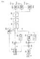
図1は、THP−SDMAを用いた第1の実施形態に従う無線送信装置を示している。パイロット系列11及びデータ系列12は、それぞれ変調部101及び102によって変調が施され、変調シンボル、すなわちパイロット信号13及びデータ信号14が生成される。変調部101及び102では、従来知られている種々のデジタル変調方式、例えばBPSK(Binary Phase Shift Keying)、QPSK(Quadrature Phase Shift Keying)、ASK(Amplitude Shift Keying)、FSK(Frequency Shift Keying)、16QAM(16 Quadrature Amplitude Modulation)、あるいは64QAMなどの変調方式が利用される。<Wireless transmitter>
FIG. 1 shows a radio transmission apparatus according to the first embodiment using THP-SDMA. The
変調部101から出力されるパイロット信号13は、ビームフォーマ106に直接入力される。一方、変調部102から出力されるデータ信号14は、減算部103とモジュロ演算部104及びフィードバック部105からなるブロックにより処理される。すなわち、データ信号14は減算部103及びフィードバック部105によりフィードバック処理が行われ、さらにフィードバック処理後のデータ信号に対してモジュロ演算部104によりモジュロ演算が行われる。フィードバック部105では、減算部103から出力されるデータ信号に対してあるゲインを乗じる処理を行う。減算部103とモジュロ演算部104及びフィードバック部105によるフィードバック処理及びモジュロ演算後のデータ信号15は、ビームフォーマ106に入力される。 The
ビームフォーマ106では、パイロット信号13とフィードバック処理及びモジュロ演算後のデータ信号15に対して、複数のユーザ(無線端末)向けの送信ビーム形成する処理、すなわちビームフォーミング処理がされる。直交周波数分割多重(Orthogonal Frequency-Division Multiplexing(OFDM))伝送あるいは直交周波数分割多重アクセス(OFDMA)を用いる場合、ビームフォーミング処理後のパイロット信号及びデータ信号は、逆高速フーリエ変換(inverse fast Fourier transformer(IFFT))ユニット107によりOFDM信号に変換された後、デジタル−アナログ変換器(DAC)108によりアナログ信号に変換され、複数(n)の送信RF(Radio Frequency)部109−1〜109−nに入力される。なお、シングルキャリア伝送の場合、つまりOFDM伝送やOFDMA伝送のようなマルチキャリア伝送を用いない場合、IFFTユニット107は必要なく、ビームフォーマ106からの出力信号はDAC108に直接入力される。なお、いずれの場合もDAC108の前段に帯域制限のためのディジタルフィルタなどを用いることもある。 In the
送信RF部109−1〜109−nは、周波数変換器(アップコンバータ)、電力増幅器及び必要に応じてフィルタを有する。DAC108からのアナログ信号に変換されたパイロット信号及びデータ信号は、送信RF部109−1〜109−nにおいてRF帯の周波数にアップコンバートされ、さらに電力増幅がなされた後、送信アンテナ110−1〜110−nに供給されることによって送信される。 The transmission RF units 109-1 to 109-n include a frequency converter (upconverter), a power amplifier, and a filter as necessary. The pilot signal and the data signal converted into the analog signal from the
<無線受信装置>
図2は、第1の実施形態に従う無線受信装置を示している。図2に示す無線受信装置は基地局に備えられる図1の無線送信装置に対応して、複数のユーザの無線端末にそれぞれ備えられる。図1の無線送信装置から送信されるRF信号は、受信アンテナ301によって受信される。受信アンテナ301から出力される受信信号31は、受信RF部302に入力される。<Wireless receiver>
FIG. 2 shows a wireless reception device according to the first embodiment. The radio reception apparatus shown in FIG. 2 corresponds to the radio transmission apparatus of FIG. 1 provided in the base station, and is provided in radio terminals of a plurality of users. The RF signal transmitted from the wireless transmission device in FIG. 1 is received by the
受信RF部302は、低雑音増幅器(LNA)、周波数変換器(ダウンコンバータ)、及び必要に応じてフィルタを有する。受信信号31は、受信RF部302において増幅された後、RF帯から例えばベースバンド帯の周波数にダウンコンバートされる。 The
受信RF部302から出力されるベースバンド帯の受信信号は、アナログ−デジタル変換器(ADC)303によってアナログ信号からデジタル信号に変換された後、高速フーリエ変換(fast Fourier transformer(FFT))ユニット304により復調(サブキャリア復調)される。FFTユニット304からの出力信号は、モジュロ演算部305及びチャネル推定部306に入力される。モジュロ演算部305及びチャネル推定部306からの出力信号は、復調部307に入力される。 A baseband received signal output from the
ここでは、図1の無線送信装置がOFDM伝送のようなマルチキャリア伝送を用いていることに対応して、無線受信装置にFFTユニット304が設けられているが、シングルキャリア伝送の場合にはFFTユニット304は不要であり、ADC303からの出力信号はモジュロ演算部305及びチャネル推定部306に直接入力される。なお、いずれの場合もADC303の後に帯域制限のためのディジタルフィルタを用いることもある。 Here, in response to the fact that the wireless transmission device of FIG. 1 uses multicarrier transmission such as OFDM transmission, an
モジュロ演算部305では、図1中のモジュロ演算部104に対応したモジュロ演算が行われる。チャネル推定部306では、無線送信装置の送信アンテナ110−1〜110−nと各無線受信装置との間のチャネル推定、すなわち伝搬路応答(以下、チャネル応答という)の推定が行われる。復調部307は、チャネル推定部306からのチャネル推定値に基づいてFFTユニット304からの出力信号に対してチャネル等化を行った後、図1中の変調部101及び102の変調に対応した復調処理、すなわち変調信号を信号点へデマッピングする処理を行う。 The
チャネル推定部306は、例えば図3に示されるように2つのメモリ401及び402と直交処理部403及び除算部(ビットシフト部)404を有する。チャネル推定部306の詳細な処理については後に説明する。 The
<詳細説明>
次に、本実施形態に従う無線送信装置及び無線受信装置について、従来のZF−SDMA、DPC−SDMA及びTHP−SDMAの詳細と共に詳しく説明する。
本実施形態に従う無線送信装置は、例えば基地局と複数のユーザによって所持される無線端末とを有する無線通信システムの基地局に備えられる。無線通信システムは、複数のアンテナを用いて同一周波数、同一時間に複数のユーザ(無線端末)を多重するSDMA方式を利用している。<Detailed explanation>
Next, the radio transmitting apparatus and radio receiving apparatus according to the present embodiment will be described in detail together with details of conventional ZF-SDMA, DPC-SDMA, and THP-SDMA.
The radio transmission apparatus according to the present embodiment is provided in a base station of a radio communication system having, for example, a base station and radio terminals possessed by a plurality of users. A wireless communication system uses an SDMA scheme in which a plurality of users (wireless terminals) are multiplexed at the same frequency and the same time using a plurality of antennas.
基地局は2つの送信アンテナTx1及びTx2(例えば、図1中のアンテナ110−1及び110−2に相当)を持ち、ユーザ1及びユーザ2の無線端末はそれぞれ1本の受信アンテナRx1及びRx2を持っていると仮定する。ユーザ1及びユーザ2の無線端末への送信信号をそれぞれ
とし、ユーザ1及びユーザ2の無線端末で受信される雑音信号を
とすると、ユーザ1及びユーザ2の無線端末で受信される信号yは
と書くことができる。ここでHは基地局と無線端末間のチャネル行列であり、h11は送信アンテナTx1からユーザ1の無線端末の受信アンテナRx1までのチャネル応答、h12は送信アンテナTx2から受信アンテナRx1までのチャネル応答、h21は送信アンテナTx1からユーザ2の無線端末の受信アンテナRx2までのチャネル応答、h22は送信アンテナTx2から受信アンテナRx2までのチャネル応答をそれぞれ示す。Can be written. Here, H is a channel matrix between the base station and the wireless terminal, h11 is a channel response from the transmitting antenna Tx1 to the receiving antenna Rx1 of the wireless terminal of the
ここで、ビームフォーマを用いて送信信号s(パイロット信号及びデータ信号)に対して
というウェイトWを乗算して送信すると、
となり、ユーザ1及びユーザ2の無線端末は互いに干渉なく、それぞれs1及びs2のみを受信することが可能になり、SDMAを実現できる。これがZF−SDMAである。Thus, the wireless terminals of
一方、非特許文献1に記載されたDPC−SDMAについて図4及び図5を用いて説明する。ZF−SDMAでは、前述したようにチャネル行列Hのエルミート転置HHをQR分解して得られるQを用いる。具体的には、
として計算されたQをウェイトWとして用いる。ここで、Qは直交行列であり、かつユニタリ行列であるから、ZF−SDMAで問題になる送信電力の増加は生じない。Is used as the weight W. Here, since Q is an orthogonal matrix and a unitary matrix, an increase in transmission power that is a problem in ZF-SDMA does not occur.
ビームフォーミングによって送信信号にウェイトWを乗算すると、ユーザ1及びユーザ2の無線端末の受信信号は次のようになる。
よって、ユーザ1の無線端末はユーザ1向けの送信信号s1のみを受信し、ユーザ2の無線端末はユーザ1向けの送信信号s1及びユーザ2向けの送信信号s2の両方を受信する。Therefore, the wireless terminal of the
図4は、このときのウェイトWが作るビームのイメージを示している。図4の例では、ユーザ1向けの送信信号s1はユーザ1の無線端末において最大ゲインが得られるようなビームで送信される。このユーザ1向けのビームについては、干渉抑圧を考慮する必要がないため、最大比合成ダイバーシチのためのビームとすることが可能になり、ZF−SDMAよりも特性が良い。FIG. 4 shows an image of the beam created by the weight W at this time. In the example of FIG. 4, the transmission signal s1 for the
ユーザ1の無線端末の受信信号は、y1=r11*s1 + n1となる。このとき、ユーザ1の無線端末のダイバーシチオーダは1となる。このユーザ1向けのビームはユーザ2の無線端末を考慮していないため、ユーザ1向けの送信信号s1はユーザ2の無線端末にも届いてしまう。一方、ユーザ2向けの送信信号s2は、ユーザ1の無線端末への干渉を抑圧する必要がある。その結果、ユーザ2向けの送信信号s2は、ユーザ1の無線端末には届かないものの、ユーザ2の無線端末にも最大利得で届かず、ユーザ2の無線端末のダイバーシチオーダは1になる。The reception signal of the wireless terminal of
ところで、このままではユーザ2の無線端末はユーザ1向けの送信信号s1からの干渉を受けてしまうことになる。すなわち、ユーザ2の無線端末の受信信号はy2=r21*s1 + r22*s2 + n2となり、ここでr21*s1がs1からの干渉成分である。そこで、DPC−SDMAでは図5に示されるように送信信号s1及びs2にフィードバック処理を含むプリコーディングを施してから、ビームフォーミングを行う。図5では、次式で示すプリコーディング信号s’を生成する。
このようなプリコーディング(符号化は処理)を施すと、プリコーディング信号s’にウェイトWによるビームフォーミングを施して得られる最終的な送信信号x’は次式となる。
このときの受信信号y’は次のように書くことができる。
すなわち、図5に示されるようにユーザ1の無線端末の受信信号は、プリコーディングを行わない図4の場合と同様にy1=r11*s1 + n1となる。一方、ユーザ2の無線端末の受信信号は、y2=r22*s2 + n2となり、干渉成分r21*s1がキャンセルされる。このようにビームフォーミングとプリコーディングを併用することにより、ユーザ1及びユーザ2の無線端末は互いの干渉なく基地局と通信を行うことが可能になる。That is, as shown in FIG. 5, the received signal of the wireless terminal of
ところで、式(10)で示したように、送信信号に対してキャンセリングのみの目的のプリコーディング、すなわちフィードバック処理のみを施した場合、フィードバック処理後の送信信号sは以下のようになる。
ここで、s1及びs2の電力を1とした場合、s2-s1r12(1)*/ r22(1)*は1より大きくなってしまう可能性があるため、送信電力が増大するという問題がある。この問題を避けるため、前述したように非特許文献2においてTHPを用いた送信電力低減方法、すなわち複素数で構成される送信信号にモジュロ演算を施す方法が提案されている。以下、この非特許文献2で提案されている送信電力低減方法の原理と問題点について、図6及び図7を参照して説明する。図6は送信信号点のIQ平面上でのコンスタレーションを示し、図7は受信信号点のIQ平面上でのコンスタレーションを示している。Here, if the power of s1 and s2 is 1, s2 -s1 r12(1) * / r22(1) * may be larger than 1, so the transmission power is There is a problem of increasing. In order to avoid this problem, as described above,
まず、キャンセリング前の送信信号のs1及びs2の振幅Aを下記で表すとする。
ここで、Mは変調多値数、mは電力を1に規格化するための係数であり、QPSKの場合はM=4、m=√2である。Here, M is the modulation multi-value number, m is a coefficient for normalizing the power to 1, and in the case of QPSK, M = 4 and m = √2.
今、図6の左上の送信信号点s2がキャンセリング後、右上の点s2’に移った場合を考える。このときTHPによれば、フィードバック処理後の送信信号s2 - s1r12(1)*/ r22(1)*と、次式に示すNの整数倍との減算または加算を実軸及び虚軸上で、すなわちI相及びQ相に対して行い、振幅が±√M/m以内、すなわち±√2以内になるようにして電力低減を行う。
この処理はモジュロ(Modulo)演算であるため、この処理を非特許文献1においてはModulo reductionとも呼んでいる。 Since this process is a modulo operation, this process is also called Modulo reduction in
今、モジュロ演算においてI相に対してNを1回、Q相に対してNを1回減算し、
としたときに振幅が±√2以下になり、この値を用いてウェイトを施して送信を行う場合を考える。すなわち、点s2’が矢印のように振幅がA以内の点s2”に移ったとする。Let us consider a case where the amplitude is ± √2 or less and transmission is performed with weights using this value. That is, the point s2 'is amplitude as arrows and moved to s2 "points within A.
このとき受信側では、雑音成分を無視すれば
が受信されるため、これをチャネル応答に相当するゲインr22*で除算すると、受信信号s1-N-jNは図7の白抜き点y/r222となる。この受信信号はフィードバック処理前の振幅Aを超えているため、受信側ではI相及びQ相で1回ずつ式(13)のNを加算することで、信号s2を再生することが可能になる。この方式が前述したTHP−SDMAであり、送信電力を増加させることなくユーザを同一時間、同一周波数で多重しながら、かつ従来のSDMA方式より受信品質を改善できるという特徴がある。Is divided by the gain r22* corresponding to the channel response, the received signal s1 -N-jN becomes a white dot y / r222 in FIG. Since this received signal exceeds the amplitude A before the feedback processing, it is possible to reproduce the signal s2 by adding N in Expression (13) once for the I phase and Q phase at the receiving side. Become. This method is the THP-SDMA described above, and has the characteristics that the reception quality can be improved over the conventional SDMA method while multiplexing users at the same time and the same frequency without increasing the transmission power.
ところで、THP−SDMAによって送信される式(10)に示されるような信号を受信側で復号する際には、例えばユーザ1の無線端末は受信信号をチャネル応答に相当するゲイン(受信ゲイン)r11*で除算する必要がある。チャネル応答に相当するゲインは受信側では既知でないため、予め送信側からチャネル推定のためのパイロット信号を用いて受信側に通知する必要がある。By the way, when a signal as shown in Expression (10) transmitted by THP-SDMA is decoded on the receiving side, for example, the wireless terminal of
ここで、パイロット信号を送信する際に、ビームフォーミングのためにデータ信号を送信するときと同じウェイトを利用する手法が知られている。もし、この手法をTHP−SDMAに適用すると、式(8)に示したように送信電力が増加した場合、送信電力の増加を防ぐためにパイロット信号にモジュロ演算を施すと、受信信号は式(15)に示すようになってしまう。従って、受信側で受信信号を既知のパイロット信号に相当するs2で除算すると、チャネル推定値r*est22は以下のようになる。
式(16)のチャネル推定値r*est22は、本来の値r22*から大きくかけ離れてしまっているので、このままでは受信性能を大幅に劣化させてしまう。一方、モジュロ演算を施さずにパイロット信号を送信すれば、この問題を回避できるが、増大した送信電力を規格化することになるため、結果的にパイロット信号の受信レベルを下げてしまうことになり、やはり受信品質を低下させてしまう。Channel estimation valuer* est22 of formula (16), since they've far removed from the original value r22*, thereby significantly degrading the receiving performance in this state. On the other hand, if the pilot signal is transmitted without performing the modulo operation, this problem can be avoided. However, since the increased transmission power is standardized, the reception level of the pilot signal is lowered as a result. As a result, the reception quality is degraded.
本実施形態の無線送信装置では、上記のようにTHP−SDMAにおいて正確なチャネル推定値が得られないことに起因して受信特性が劣化するという問題を解決するため、データ信号14に対してのみ減算部103とモジュロ演算部104及びフィードバック部105による処理を行ってから、ビームフォーマ106によるビームフォーミングを行う。パイロット信号13についてはデータ信号14に対する上記の処理を経ずに、ビームフォーマ106によるビームフォーミングを行う。以下、この点について詳細に説明する。 In the radio transmission apparatus of the present embodiment, in order to solve the problem that the reception characteristics deteriorate due to the fact that an accurate channel estimation value cannot be obtained in THP-SDMA as described above, only the data signal 14 is After the processing by the
変調部102から出力されるデータ信号14は、減算部103とモジュロ演算部104及びフィードバック部105からなるブロックにより、データ信号に関する式(10)のB-1の処理に相当するフォードバック処理が行われる。減算器103及びフィードバック部105では、式(8)の2行目のフィードバック処理が行われる。すなわち、フィードバック部105では減算器103から出力されるデータ信号(ユーザ1向けの送信信号s1及びユーザ2向けの送信信号s2)のうちs1にr12*/ r22*というゲインを乗じてs1r12*/ r22*を生成し、減算部103ではユーザ2向け送信信号s2からs1r*12/ r22*を差し引いてs2-s1r12*/ r22*を生成する。The data signal 14 output from the
モジュロ演算部104は、フィードバック処理によって生じる送信電力の増加を低減させ、式(12)のようにNの整数倍をI相あるいはQ相に加算あるいは減算して規定の送信電力になるように調整を行う。 The modulo
減算部103とモジュロ演算部104及びフィードバック部105からなるブロックから出力されるフィードバック処理及びモジュロ演算後の信号15は、ビームフォーマ106へ入力される。ビームフォーマ106では、フィードバック処理及びモジュロ演算後の信号15に対して、式(10)におけるビームフォーミング行列Qがウェイトとして乗算されることにより、ビームフォーミングが行われる。ビームフォーミング行列Qは、ここではユニタリ行列である。 A
一方、変調部101から出力されるパイロット信号13はビームフォーマ106に直接入力される。データ信号14に対するビームフォーミング処理と同様に、パイロット信号13に施されるビームフォーミング処理も、本例ではユニタリ行列であるビームフォーミング行列Qによってなされるため、パイロット信号の送信電力が増大することはない。 On the other hand, the
このように本実施形態によると、パイロット信号13はフィードバック処理が施されないので、大幅な送信電力の増大は生じない。このためパイロット信号13については、電力正規化を施さずに送信することが可能になる。よって、パイロット信号13に電力低減のためのモジュロ演算を施す必要がないため、従来の問題が解決される。 As described above, according to the present embodiment, the
なお、本実施形態ではQをユニタリ行列としたので、ビームフォーマ106における入力の電力と出力の電力が保存されるが、Qは必ずしもユニタリ行列でなくともよく、直交行列に近ければよい。 In this embodiment, since Q is a unitary matrix, the input power and the output power in the
次に、図2の無線受信装置について詳しく説明する。パイロット信号は図1の無線送信装置においてフィードバック処理が施されないため、無線受信装置における受信パイロット信号ypは以下のようになる。
ここで、p1はユーザ1向けパイロット信号を表し、p2はユーザ2向けパイロット信号を表す。Here, p1 represents a pilot signal for
よって、ユーザ1の無線端末における受信パイロット信号はyp1=r11*p1 + n1となる。雑音成分n1を無視すれば、既知のパイロット信号p1で受信パイロット信号yp1を除算することにより、チャネル推定値r11*を求めることが可能になる。Therefore, the received pilot signal at the wireless terminal of
一方、ユーザ2の無線端末における受信パイロット信号はyp2=r12*p1 + r22*p2 + n2となる。このため、既知のパイロット信号p2で受信パイロット信号yp2を除算しても、ユーザ1の無線端末からの干渉成分r12p1*があるために正しいチャネル推定値r22*を求めることはできない。そこで、本実施形態では好ましくは以下のようにパイロット信号を構成する。On the other hand, the received pilot signal at the wireless terminal of
図8(a)及び(b)は、本実施形態におけるパイロット信号の第1の構成例を説明するためのユーザ1向け送信信号及びユーザ2向け送信信号を示しており、横軸は周波数、縦軸は時間をそれぞれ表す。図8(a)及び(b)において斜線を施した丸印はデータ信号のサブキャリアを示し、白抜きの丸印はパイロット信号のサブキャリアを示す。この例では、データ信号は周波数f1,f2,f4,f5のサブキャリアに割り当てられ、パイロット信号は周波数f3のサブキャリアに割り当てられる。 FIGS. 8A and 8B show a transmission signal for
図8(a)のユーザ1向け送信信号中の第1のパイロット信号は式(17)中のp1を表し、図8(b)中のユーザ2向け送信信号中の第2のパイロット信号は式(17)中のp2を表す。周波数f3のサブキャリアを表す白抜きの丸印に書かれた“1”はパイロット信号が送信されることを表し、“0”はパイロット信号が送信されないことを表す。このように図8(a)に示されるユーザ1向け送信信号中の第1のパイロット信号と、図8(b)に示されるユーザ2向け送信信号中のパイロット信号とは、時間方向において互いに直交している。 The first pilot signal in the transmission signal for
図8(a)及び(b)のようなユーザ1向け送信信号及びユーザ2向け送信信号を送信すると、時刻t1の受信パイロット信号yp,t1は式(17)より次式で与えられる。
このように時刻t1では、ユーザ1の無線端末へのみパイロット信号を送信する。これより明らかに、ユーザ1の無線端末は受信信号よりチャネル推定値r11*を求めることが可能になる。ユーザ2の無線端末では、時刻t1において復調に必要のない信号r12*が得られるため、ユーザ2の無線端末はこの信号r12*を無視することになる。Thus, at time t1, a pilot signal is transmitted only to the wireless terminal of
一方、時刻t2の受信パイロット信号yp,t2は式(17)より次式で与えられる。
これより明らかにユーザ2の無線端末では復調に必要なチャネル推定値r22*が得られ、ユーザ1の無線端末にはパイロット信号が届かないことが分かる。This clearly shows that the
このように時刻t1及びt2の2シンボル区間を用いることで、ユーザ1及びユーザ2の無線端末は共にチャネル推定値を正確に求めることが可能になる。 As described above, by using the two symbol periods at the times t1 and t2, it is possible for both the wireless terminals of the
図9(a)及び(b)は、本実施形態におけるパイロット信号の第2の構成例を説明するためのユーザ1向け送信信号及びユーザ2向け送信信号を示しており、図の見方は図8(a)及び(b)と同様である。この場合、時刻t1における受信パイロット信号yp,t1は式(17)より次式で与えられる。
同様に、時刻t2における受信パイロット信号yp,t2は次式で与えられる。
このように図9(a)に示されるユーザ1向け送信信号中の第1のパイロット信号と、図9(b)に示されるユーザ2向け送信信号中のパイロット信号とは、図8(a)及び(b)と同様に時間方向において互いに直交している。 As described above, the first pilot signal in the transmission signal for
なお、図8(a)及び(b)及び図9(a)及び(b)では、データ信号とパイロット信号を異なる周波数に割り当てたが、図10(a)(b)及び図11(a)及び(b)に示すように、データ信号とパイロット信号を異なる時間に割り当ててもよい。この場合、図10(a)に示されるユーザ1向け送信信号中の第1のパイロット信号と、図10(b)に示されるユーザ2向け送信信号中のパイロット信号とは、周波数方向において互いに直交している。同様に、図11(a)に示されるユーザ1向け送信信号中の第1のパイロット信号と、図11(b)に示されるユーザ2向け送信信号中のパイロット信号とは、周波数方向において互いに直交している。 In FIGS. 8A and 8B and FIGS. 9A and 9B, the data signal and the pilot signal are assigned to different frequencies, but FIGS. 10A, 10B, and 11A are used. And as shown to (b), you may allocate a data signal and a pilot signal at different time. In this case, the first pilot signal in the transmission signal for
次に、図3に示したチャネル推定部306の処理について説明する。図7において、メモリ401及び402はそれぞれ時刻t1及びt2における受信パイロット信号を保持している。直交処理部403は、メモリ401及び402に保持されているパイロット信号に対して直交処理を行い、パイロット信号の分離を行う。除算部404では、直交処理部403により分離されたパイロット信号の値を規格化してチャネル推定を行う。 Next, processing of
例えば、ユーザ1の無線端末に着目すると、メモリ401に式(18)の一行目(yp,t1(1))が保持され、メモリ402に式(19)の一行目(yp,t2(1))が保持される。同様にユーザ2の無線端末においては、メモリ401に式(18)の二行目(yp,t1(2))が保持され、メモリ402に式(19)の二行目(yp,t2(2))が保持される。直交処理部403と除算部404では、具体的には次の処理が行われる。For example, when attention is paid to
ユーザ1の無線端末では、メモリ401および402に保持されている信号が直交処理部403で加算され、次いで除算部404において“2”で除算される。この処理を数式で表現すると、下記のようになる。
ユーザ2の無線端末では、次式に示すようにメモリ401および402に保持されている信号が直交処理部403で減算され、次いで除算部404において“2”で除算される。
なお、除算部404において直交処理部403からの出力信号を“2”で除算する処理については、ビットシフトで実現することも可能である。 Note that the processing of dividing the output signal from the
このようにユーザ1及びユーザ2の無線端末ともに、チャネル推定を正しく行うことが可能になる。これは図8(a)及び(b)及び図9(a)及び(b)に示したように、パイロット信号がユーザ1及びユーザ2間で時間方向において互いに直交しているためである。図10(a)及び図11(a)及び(b)に示したようにパイロット信号がユーザ1及びユーザ2間で周波数方向において直交している場合も、同様の効果が得られることは明らかである。 Thus, it is possible to correctly perform channel estimation for both the
図8(a)及び(b)及び図10(a)及び(b)に示した第1のパイロット信号構成は、受信側での処理を必要とせずそのまま簡易にチャネル推定値が求められるという特徴がある。一方、第1のパイロット信号構成は、パイロット信号を送信しない区間があったのに対して、図9(a)及び(b)及び図11(a)及び(b)に示した第2のパイロット信号構成は、常にパイロット信号が送信されているために電力効率が良い。実際、第2のパイロット信号構成によると、受信側では受信パイロット信号の2シンボルを同相加算してチャネル推定値を求めるため、より正確なチャネル推定を行うことが可能になる。 The first pilot signal configuration shown in FIGS. 8 (a) and 8 (b) and FIGS. 10 (a) and 10 (b) is characterized in that a channel estimation value can be easily obtained without requiring any processing on the receiving side. There is. On the other hand, the first pilot signal configuration includes a section in which no pilot signal is transmitted, whereas the second pilot shown in FIGS. 9A and 9B and FIGS. 11A and 11B. The signal configuration is good in power efficiency because the pilot signal is always transmitted. Actually, according to the second pilot signal configuration, since the reception side obtains a channel estimation value by performing in-phase addition of two symbols of the reception pilot signal, more accurate channel estimation can be performed.
以上述べたように、第1の実施形態によればTHP−SDMAおいてパイロット信号の送信にはフィードバック処理さらにはモジュロ演算を行わず、ビームフォーミング処理のみを適用することにより、送信電力を増大させることなくパイロット信号を送信することが可能になる。従って、受信側においてはパイロット信号がより強いレベルで正確に受信されることにより、正確なチャネル推定値を求めることが可能となり、もって受信特性の改善を図ることができる。 As described above, according to the first embodiment, in THP-SDMA, the transmission power is increased by applying only the beam forming process without performing the feedback process and the modulo operation for the pilot signal transmission. The pilot signal can be transmitted without any problem. Therefore, on the receiving side, since the pilot signal is accurately received at a stronger level, it is possible to obtain an accurate channel estimation value, thereby improving the reception characteristics.
以上の説明では、2ユーザすなわちユーザ1及びユーザ2の無線端末にパイロット信号を送信する場合について説明をしたが、パイロット信号のユーザ間の直交化に用いる直交系列を増やせば、2以上のユーザにパイロット信号を送信する場合についても同様の効果を得ることが可能である。 In the above description, the case where pilot signals are transmitted to two users, that is, the wireless terminals of
(第2の実施形態)
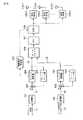
次に、図12を用いて本発明の第2の実施形態について説明する。図1に示した第1の実施形態に従う無線送信装置との相違点について述べると、本実施形態に従う無線送信装置では、図1中に示したパイロット系列のための変調部101が除去されるとともに、パイロット信号選択部201、パイロット信号演算部202、減算部203、フィードバック部205及び電力計算部206が追加されている。(Second Embodiment)
Next, a second embodiment of the present invention will be described with reference to FIG. The difference from the radio transmission apparatus according to the first embodiment shown in FIG. 1 will be described. In the radio transmission apparatus according to this embodiment, the
パイロット信号選択部201では、複数の異なるパイロット信号の候補が予め用意(保持)されおり、電力計算部206により計算された送信電力に従って一つのパイロット信号が選択される。選択されたパイロット信号13は、減算部203及びフィードバック部205により、フォードバック処理が行われる。この場合、減算部203及びフィードバック部205では、式(10)あるいは後述する式(25)におけるB-1を乗算する処理が行われる。フィードバック処理後のパイロット信号は、ビームフォーマ部106に入力されるとともに、電力計算部206にも入力される。Pilot
いま、具体的にチャネル行列Hが
であるとする。QR分解を用いた手法を適用すると、受信信号yは式(10)に従って次式のようになる。
パイロット信号選択部201は、前述したようにパイロット信号の様々な候補(パイロット信号セットという)を予め用意している。例えば、セット1は(1,1)T、セット2は(1,-1)T、セット3は(-1,1)T、そしてセット4は(-1,-1)Tであるとする。電力計算部206において、パイロット信号選択部201がそれぞれのパイロット信号セットを選択した場合の送信電力が計算され、最も送信電力が小さくなる一つのパイロット信号セットがパイロット信号選択部201によって選択される。The pilot
ここで、QR分解を用いた手法ではQHがユニタリになる。このため、ビームフォーマ106においてQH(ウェイトW)をパイロット信号に乗算する前後で電力が変わらないため、図12のようにビームフォーマ106の前段で電力計算を行うことが可能である。もし、QHがユニタリ行列、あるいは直交行列でない場合、ビームフォーマ106の後段で電力を測定すればよい。Here, in the method using QR decomposition, QH becomes unitary. For this reason, since the power does not change before and after the pilot signal is multiplied by QH (weight W) in the
こうしてビームフォーマ106の前段で測定されたパイロット信号セットの送信電力は、上記の具体的数値例によれば、それぞれセット1が1.9177、セット2が1.0641、セット3が1.0641、セット4が1.9177となる。よって、この場合はセット2かセット3を用いることで、送信電力を最小にしてパイロット信号を送信することが可能になる。なお、ここではセット2を用いることとする。 Thus, according to the above specific numerical examples, the transmission power of the pilot signal set measured in the preceding stage of the
従って、パイロット信号選択部201では最終的にセット2が選択され、セット2のパイロット信号の送信が行われる。 Accordingly, the pilot
ここで、再び一般化した変数を用いて受信パイロット信号ypを式(10)に基づいて記述すると、以下のようになる。
受信側では送信側でどのパイロット信号セットが送信されているかの情報を持たないため、ユーザは例えば予め決められたパイロット信号セット(例えばセット1)を用いてチャネル推定を行う。その結果、ユーザ1の無線端末はr11*をチャネル推定値として、またユーザ2の無線端末は-r22*をチャネル推定値としてそれぞれ認識する。ユーザ2の無線端末では、誤ったチャネル推定値が得られることになる。このままでは、ユーザ2の無線端末は誤ったチャネル推定値でデータの復調を試みるため、誤った復調が行われてしまう。Since the receiving side does not have information on which pilot signal set is transmitted on the transmitting side, the user performs channel estimation using, for example, a predetermined pilot signal set (for example, set 1). As a result, the wireless terminal of
この問題を回避するため、パイロット選択部106で選択されたパイロット信号13は、演算部202においてデータ信号14に乗算(あるいは除算)される。これによりユーザ2の無線端末へのデータ信号は、送信信号に常に−1が乗算され、このパイロット信号がチャネル推定値-r22*と相殺されるため、正確な受信が可能になる。In order to avoid this problem, the
なお、本実施形態では送信電力が最も小さくなるパイロット信号セットを選択したが、OFDMやOFDMAなどのマルチキャリア信号の場合、複数のキャリアの合計で送信電力が決定されるため、全体で送信電力が小さくなるパイロット信号セット、あるいはPAPRが最も小さくなるようなパイロット信号セットを選択することも可能である。 In this embodiment, the pilot signal set with the smallest transmission power is selected. However, in the case of a multicarrier signal such as OFDM or OFDMA, the transmission power is determined by the sum of a plurality of carriers. It is also possible to select a pilot signal set that decreases or a pilot signal set that minimizes the PAPR.
また、本実施形態では、有限のセットから送信電力が最も小さくなるようなパイロット信号セットを選択したがセットの個数については任意であるし、セットを持たずに、例えば(1,1)Tを基本とし,アンテナ1あるいはアンテナ2のパイロット信号の位相や振幅を任意に設定して,最も送信電力が小さくなるパイロット信号をサーチしてパイロット信号として使用することも可能である。Further, in this embodiment, a pilot signal set having the smallest transmission power is selected from a finite set, but the number of sets is arbitrary, and for example, (1,1)T is set without having a set. Basically, it is possible to arbitrarily set the phase and amplitude of the pilot signal of the
このように本実施形態では、THP−SDMAにおけるパイロット信号を複数用意するため、送信電力を増大させることなくパイロット信号を送信することが可能になる。また、選択されたパイロット信号をデータ信号に乗算することにより、ユーザは選択されたパイロット信号を知らなくてもデータ信号の復調が可能になる。すなわち、受信側では正確なチャネル推定値を求めることが可能になり、受信特性の改善が可能になる。 Thus, in this embodiment, since a plurality of pilot signals in THP-SDMA are prepared, it is possible to transmit pilot signals without increasing transmission power. Further, by multiplying the data signal by the selected pilot signal, the user can demodulate the data signal without knowing the selected pilot signal. That is, an accurate channel estimation value can be obtained on the receiving side, and reception characteristics can be improved.
(第3の実施形態)
次に、図13を参照して本発明の第3の実施形態について説明する。図1に示した第1の実施形態に従う無線送信装置との相違点について述べると、本実施形態に従う無線送信装置では、パイロット信号13に対して減算部203、モジュロ演算部204及びフィードバック部205が追加されている。すなわち、本実施形態ではパイロット信号13及びデータ信号14のいずれに対してもフィードバック処理、モジュロ演算及びビームフォーマ処理が施される。さらに、本実施形態では後述する制御信号生成部207が設けられ、ここで生成された制御信号が例えばDAC108に入力されることにより、受信側へ送信される。(Third embodiment)
Next, a third embodiment of the present invention will be described with reference to FIG. The difference from the radio transmission apparatus according to the first embodiment shown in FIG. 1 will be described. In the radio transmission apparatus according to the present embodiment, a
いま、式(14)で示したように、モジュロ演算部204でI相に対してNを1回、Q相に対してNを1回減算してパイロット信号の送信電力が規定の振幅に収まった場合、モジュロ演算部204から出力されるモジュロ演算後のパイロット信号は、次式のようになる。
よって、受信パイロット信号は、以下のようなる。
この場合、ユーザ1の無線端末は予め定められたパイロット信号p1で乗算を行うことでチャネル推定値r11*を得ることが可能であるが、ユーザ2の無線端末は背景技術の問題において述べたように、このままではチャネル推定値r22*を求めることができない。そこで、本実施形態ではモジュロ演算部204の演算内容を示す情報、具体的にはモジュロ演算部204においてにおいて何回Nが信号に加算されたかを示す情報を制御信号生成部207により制御信号として生成し、これを受信側へ通知する。例えば、本実施形態の場合、I相に対して−1、Q相に対して−1という情報を制御信号により通知受信側へ通知する。この制御信号は整数を表すため、僅かなビットでよく、送信スループットを低下させることはない。In this case, the wireless terminal of
また、N=2√M/mにおけるMやmは、変調方式が決定すれば求められる値であるため、無線受信装置ではNの値を求めることが可能である。すなわち、無線受信装置ではこうして送信される制御信号を受信して復調し、得られるNを用いて式(28)におけるp2-N-jNを計算することができる。従って、こうして計算されたp2-N-jNで式(28)の受信パイロット信号を除算することにより、正しいチャネル推定値r22*を求めることが可能になる。In addition, since M and m at N = 2√M / m are values that can be obtained if the modulation method is determined, the wireless receiver can obtain the value of N. That is, the radio receiving apparatus can receive and demodulate the control signal transmitted in this way, and calculate p2 −N−jN in Expression (28) using N obtained. Therefore, by dividing the received pilot signal of Equation (28) by p2 −N−jN calculated in this way, it is possible to obtain a correct channel estimation value r22* .
このように本実施形態によってもパイロット信号を正確に送信することができ、無線受信装置においてチャネル推定を正確に行うことが可能になるため、無線受信装置の受信特性を大幅に改善することが可能になる。 As described above, according to the present embodiment, the pilot signal can be transmitted accurately, and the channel estimation can be accurately performed in the radio reception apparatus, so that the reception characteristics of the radio reception apparatus can be greatly improved. become.
なお、本発明は上記実施形態そのままに限定されるものではなく、実施段階ではその要旨を逸脱しない範囲で構成要素を変形して具体化できる。また、上記実施形態に開示されている複数の構成要素の適宜な組み合わせにより、種々の発明を形成できる。例えば、実施形態に示される全構成要素から幾つかの構成要素を削除してもよい。さらに、異なる実施形態にわたる構成要素を適宜組み合わせてもよい。 Note that the present invention is not limited to the above-described embodiment as it is, and can be embodied by modifying the constituent elements without departing from the scope of the invention in the implementation stage. In addition, various inventions can be formed by appropriately combining a plurality of components disclosed in the embodiment. For example, some components may be deleted from all the components shown in the embodiment. Furthermore, constituent elements over different embodiments may be appropriately combined.
101,102・・・変調部
103・・・減算部
104・・・モジュロ演算部
105・・・フィードバック部
106・・・ビームフォーマ
107・・・IFFTユニット
108・・・デジタル−アナログ変換器
109−1〜109−n・・・送信RF部
110−1〜110−n・・・送信アンテナ
201・・・パイロット信号選択部
201・・・演算部
203・・・減算部
204・・・モジュロ演算部
205・・・フィードバック部
206・・・電力計算部
207・・・制御信号生成部
301・・・受信アンテナ
302・・・受信RF部
303・・・アナログ−デジタル変換器
304・・・FFTユニット
305・・・モジュロ演算部
306・・・チャネル推定部
307・・・復調部DESCRIPTION OF SYMBOLS 101,102 ...
Claims (10)
Translated fromJapanese前記フィードバック処理後のデータ信号及びチャネル推定のためのパイロット信号に対してビームフォーミング処理を行うステップと、
前記ビームフォーミング処理後のデータ信号及びパイロット信号を複数のアンテナを含む送信部によって送信するステップと、を具備する無線送信方法。Performing a feedback process of subtracting the data signal fed back by multiplying the gain from the input data signal;
Performing beam forming on the data signal after the feedback processing and the pilot signal for channel estimation;
Transmitting the data signal and pilot signal after the beamforming processing by a transmitting unit including a plurality of antennas.
前記フィードバック処理後のデータ信号及びチャネル推定のためのパイロット信号に対してビームフォーミング処理を行うビームフォーマ部と、
前記ビームフォーミング処理後のデータ信号及びパイロット信号を送信する送信部と、を具備する無線送信装置。A feedback processing unit for performing a feedback process of subtracting the data signal fed back by multiplying the gain from the input data signal;
A beam former for performing beam forming on the data signal after the feedback processing and the pilot signal for channel estimation;
And a transmitter that transmits the data signal and the pilot signal after the beamforming process.
予め用意されたチャネル推定のための複数のパイロット信号から送信電力が最小となる一つのパイロット信号を選択する選択部と、
選択されたパイロット信号から第2のゲインを乗じてフィードバックされたパイロット信号を差し引く第2のフィードバック処理を行う第2のフィードバック処理部と、
前記第1のフィードバック処理後のデータ信号及び第2のフィードバック処理後のパイロット信号に対してビームフォーミング処理を行うビームフォーマ部と、
前記第1のフィードバック処理後のパイロット信号または前記ビームフォーミング処理後のパイロット信号から前記送信電力を計算する電力計算部と、
前記ビームフォーミング処理後のデータ信号及びパイロット信号を送信する送信部と、を具備する無線送信装置。A first feedback processing unit for performing a first feedback process for subtracting a data signal fed back by multiplying a first gain from an input data signal;
A selection unit for selecting one pilot signal having the minimum transmission power from a plurality of pilot signals for channel estimation prepared in advance;
A second feedback processing unit for performing a second feedback process for subtracting the pilot signal fed back by multiplying the selected pilot signal by the second gain;
A beam former for performing beam forming processing on the data signal after the first feedback processing and the pilot signal after the second feedback processing;
A power calculator that calculates the transmission power from the pilot signal after the first feedback processing or the pilot signal after the beamforming processing;
And a transmitter that transmits the data signal and the pilot signal after the beamforming process.
前記第1のフィードバック処理後のデータ信号に対して前記第1のフィードバック処理による送信電力の増大を低減するための第1のモジュロ演算を行う第1のモジュロ演算部と、
入力されるパイロット信号から第2のゲインを乗じてフィードバックされたパイロット信号を差し引く第2フィードバック処理を行う第2のフィードバック処理部と、
前記第2のフィードバック処理後のパイロット信号に対して前記第2のフィードバック処理による送信電力の増大を低減するための第2のモジュロ演算を行う第2のモジュロ演算部と、
前記第1のモジュロ演算後のデータ信号及び前記第2のモジュロ演算後のパイロット信号に対してビームフォーミング処理を行うビームフォーマ部と、
前記第2のモジュロ演算の内容を表す情報を通知する通知部と、を具備する無線送信装置。A first feedback processing unit for performing a first feedback process for subtracting a data signal fed back by multiplying a first gain from an input data signal;
A first modulo operation unit that performs a first modulo operation for reducing an increase in transmission power due to the first feedback process on the data signal after the first feedback process;
A second feedback processing unit for performing a second feedback process for subtracting a pilot signal fed back by multiplying a second gain from an input pilot signal;
A second modulo operation unit that performs a second modulo operation for reducing an increase in transmission power due to the second feedback process on the pilot signal after the second feedback process;
A beam former for performing beam forming on the data signal after the first modulo calculation and the pilot signal after the second modulo calculation;
A wireless transmission device comprising: a notification unit that notifies information representing the content of the second modulo operation.
Priority Applications (3)
| Application Number | Priority Date | Filing Date | Title |
|---|---|---|---|
| JP2008022008AJP5248130B2 (en) | 2008-01-31 | 2008-01-31 | Wireless transmission method and apparatus |
| PCT/JP2009/051151WO2009096345A2 (en) | 2008-01-31 | 2009-01-20 | Wireless transmission method and apparatus |
| US12/823,793US8249189B2 (en) | 2008-01-31 | 2010-06-25 | Wireless transmission method and apparatus |
Applications Claiming Priority (1)
| Application Number | Priority Date | Filing Date | Title |
|---|---|---|---|
| JP2008022008AJP5248130B2 (en) | 2008-01-31 | 2008-01-31 | Wireless transmission method and apparatus |
Publications (2)
| Publication Number | Publication Date |
|---|---|
| JP2009182894Atrue JP2009182894A (en) | 2009-08-13 |
| JP5248130B2 JP5248130B2 (en) | 2013-07-31 |
Family
ID=40612798
Family Applications (1)
| Application Number | Title | Priority Date | Filing Date |
|---|---|---|---|
| JP2008022008AActiveJP5248130B2 (en) | 2008-01-31 | 2008-01-31 | Wireless transmission method and apparatus |
Country Status (3)
| Country | Link |
|---|---|
| US (1) | US8249189B2 (en) |
| JP (1) | JP5248130B2 (en) |
| WO (1) | WO2009096345A2 (en) |
Cited By (12)
| Publication number | Priority date | Publication date | Assignee | Title |
|---|---|---|---|---|
| JP2011077568A (en)* | 2009-09-29 | 2011-04-14 | Sony Corp | Wireless transmission system, wireless communication device and wireless transmission method |
| JP2011077569A (en)* | 2009-09-29 | 2011-04-14 | Sony Corp | Wireless transmission system, wireless communication device, and wireless transmission method |
| JP2011109632A (en)* | 2009-10-22 | 2011-06-02 | Sony Corp | Radio transmission system, radio communication apparatus, and radio transmission method |
| WO2011087084A1 (en)* | 2010-01-15 | 2011-07-21 | シャープ株式会社 | Communication system, communication device, communication method, and processor |
| WO2011096138A1 (en)* | 2010-02-05 | 2011-08-11 | シャープ株式会社 | Transmitter apparatus, receiver apparatus, wireless communication system, transmission control method, reception control method, and processor |
| WO2011108319A1 (en) | 2010-03-01 | 2011-09-09 | シャープ株式会社 | Communication system, transmission device, reception device |
| WO2011108318A1 (en) | 2010-03-01 | 2011-09-09 | シャープ株式会社 | Communication system, transmission device, reception device, and communication method |
| WO2012117788A1 (en)* | 2011-03-01 | 2012-09-07 | シャープ株式会社 | Transmitting apparatus, receiving apparatus, communication system, communication method and integrated circuit |
| JP5444353B2 (en)* | 2009-08-12 | 2014-03-19 | 株式会社日立製作所 | Wireless communication system, base station, and wireless communication method |
| US8718544B2 (en) | 2009-08-31 | 2014-05-06 | Sony Corporation | Signal transmission device, electronic device, and signal transmission method |
| US8831073B2 (en) | 2009-08-31 | 2014-09-09 | Sony Corporation | Wireless transmission system, wireless communication device, and wireless communication method |
| WO2019215874A1 (en)* | 2018-05-10 | 2019-11-14 | 株式会社Nttドコモ | Reception device and transmission device |
Families Citing this family (16)
| Publication number | Priority date | Publication date | Assignee | Title |
|---|---|---|---|---|
| WO2010007473A1 (en)* | 2008-07-17 | 2010-01-21 | Freescale Semiconductor, Inc. | Integrated testing circuitry for high-frequency receiver integrated circuits |
| KR20100025869A (en)* | 2008-08-28 | 2010-03-10 | 한국전자통신연구원 | Apparatus and method of channel equalization using channel estimation |
| US9204349B2 (en) | 2009-02-10 | 2015-12-01 | Qualcomm Incorporated | Method and apparatus for facilitating a hand-in of user equipment to femto cells |
| US9642105B2 (en) | 2009-11-17 | 2017-05-02 | Qualcomm Incorporated | Access terminal-assisted time and/or frequency tracking |
| US9392562B2 (en) | 2009-11-17 | 2016-07-12 | Qualcomm Incorporated | Idle access terminal-assisted time and/or frequency tracking |
| US9756553B2 (en) | 2010-09-16 | 2017-09-05 | Qualcomm Incorporated | System and method for assisted network acquisition and search updates |
| WO2013089191A1 (en)* | 2011-12-13 | 2013-06-20 | 京セラ株式会社 | Mobile terminal, wireless communication system, and wireless communication method |
| US9155057B2 (en) | 2012-05-01 | 2015-10-06 | Qualcomm Incorporated | Femtocell synchronization enhancements using access probes from cooperating mobiles |
| US9237530B2 (en)* | 2012-11-09 | 2016-01-12 | Qualcomm Incorporated | Network listen with self interference cancellation |
| CN104144136B (en) | 2013-05-10 | 2017-12-15 | 华为技术有限公司 | The sending method and device of user's DRS (Dedicated Reference Signal) |
| US10205491B2 (en)* | 2015-09-28 | 2019-02-12 | Futurewei Technologies, Inc. | System and method for large scale multiple input multiple output communications |
| CN110799995A (en) | 2017-06-29 | 2020-02-14 | 首选网络株式会社 | Data recognizer training method, data recognizer training device, program, and training method |
| EP3923484A1 (en) | 2017-08-11 | 2021-12-15 | FRAUNHOFER-GESELLSCHAFT zur Förderung der angewandten Forschung e.V. | Concepts for transmitting data to one or more users |
| US11777539B2 (en)* | 2018-10-31 | 2023-10-03 | Avago Technologies International Sales Pte. Limited | Rate control with transmitter power optimization |
| WO2023117073A1 (en)* | 2021-12-22 | 2023-06-29 | Nokia Technologies Oy | Peak-to-average power ratio limitation |
| JP7711030B2 (en)* | 2022-06-15 | 2025-07-22 | 株式会社東芝 | Wireless power supply device and method |
Citations (2)
| Publication number | Priority date | Publication date | Assignee | Title |
|---|---|---|---|---|
| JP2007020160A (en)* | 2005-06-20 | 2007-01-25 | Ntt Docomo Inc | Apparatus for signaling information on communication link assignment and apparatus for determining communication link assignment |
| US20070253508A1 (en)* | 2006-04-19 | 2007-11-01 | Samsung Electronics Co., Ltd. | Apparatus and method for selecting effective channel in a multi-user MIMO system |
Family Cites Families (4)
| Publication number | Priority date | Publication date | Assignee | Title |
|---|---|---|---|---|
| EP1766806B1 (en)* | 2004-06-22 | 2017-11-01 | Apple Inc. | Closed loop mimo systems and methods |
| WO2006073893A2 (en)* | 2005-01-05 | 2006-07-13 | Atc Technologies, Llc | Adaptive beam forming with multi-user detection and interference reduction in satellite communiation systems and methods |
| US7949318B2 (en)* | 2007-02-05 | 2011-05-24 | Nec Laboratories America, Inc. | Multi-rank beamforming precoding apparatus and method |
| JP6012472B2 (en)* | 2010-01-07 | 2016-10-25 | マーベル ワールド トレード リミテッド | Dedicated reference signal (DRS) precoding granularity notification, method, communication apparatus and mobile communication terminal |
- 2008
- 2008-01-31JPJP2008022008Apatent/JP5248130B2/enactiveActive
- 2009
- 2009-01-20WOPCT/JP2009/051151patent/WO2009096345A2/enactiveApplication Filing
- 2010
- 2010-06-25USUS12/823,793patent/US8249189B2/enactiveActive
Patent Citations (2)
| Publication number | Priority date | Publication date | Assignee | Title |
|---|---|---|---|---|
| JP2007020160A (en)* | 2005-06-20 | 2007-01-25 | Ntt Docomo Inc | Apparatus for signaling information on communication link assignment and apparatus for determining communication link assignment |
| US20070253508A1 (en)* | 2006-04-19 | 2007-11-01 | Samsung Electronics Co., Ltd. | Apparatus and method for selecting effective channel in a multi-user MIMO system |
Cited By (32)
| Publication number | Priority date | Publication date | Assignee | Title |
|---|---|---|---|---|
| JP5444353B2 (en)* | 2009-08-12 | 2014-03-19 | 株式会社日立製作所 | Wireless communication system, base station, and wireless communication method |
| US9281860B2 (en) | 2009-08-31 | 2016-03-08 | Sony Corporation | Wireless transmission system, wireless communication device, and wireless communication method |
| US10447514B2 (en) | 2009-08-31 | 2019-10-15 | Sony Corporation | Wireless transmission system, wireless communication device, and wireless communication method |
| US8831073B2 (en) | 2009-08-31 | 2014-09-09 | Sony Corporation | Wireless transmission system, wireless communication device, and wireless communication method |
| US8718544B2 (en) | 2009-08-31 | 2014-05-06 | Sony Corporation | Signal transmission device, electronic device, and signal transmission method |
| US9544007B2 (en) | 2009-08-31 | 2017-01-10 | Sony Corporation | Wireless transmission system, wireless communication device, and wireless communication method |
| US9912502B2 (en) | 2009-08-31 | 2018-03-06 | Sony Corporation | Wireless transmission system, wireless communication device, and wireless communication method |
| JP2011077569A (en)* | 2009-09-29 | 2011-04-14 | Sony Corp | Wireless transmission system, wireless communication device, and wireless transmission method |
| US8687725B2 (en) | 2009-09-29 | 2014-04-01 | Sony Corporation | Wireless transmission system, wireless communication device and wireless transmission method |
| JP2011077568A (en)* | 2009-09-29 | 2011-04-14 | Sony Corp | Wireless transmission system, wireless communication device and wireless transmission method |
| US8988993B2 (en) | 2009-09-29 | 2015-03-24 | Sony Corporation | Wireless transmission system, wireless communication device and wireless transmission method |
| RU2542335C2 (en)* | 2009-09-29 | 2015-02-20 | Сони Корпорейшн | System, device and method of radio communication |
| JP2011109632A (en)* | 2009-10-22 | 2011-06-02 | Sony Corp | Radio transmission system, radio communication apparatus, and radio transmission method |
| US8781412B2 (en) | 2009-10-22 | 2014-07-15 | Sony Corporation | Radio transmission system, radio communication apparatus, and radio transmission method |
| JP2011146995A (en)* | 2010-01-15 | 2011-07-28 | Sharp Corp | Communication system, communication device, communication method, and processor of the same |
| WO2011087084A1 (en)* | 2010-01-15 | 2011-07-21 | シャープ株式会社 | Communication system, communication device, communication method, and processor |
| JP2011166317A (en)* | 2010-02-05 | 2011-08-25 | Sharp Corp | Transmitter, receiver, radio communication system, transmission control method, reception control method, and processor |
| WO2011096138A1 (en)* | 2010-02-05 | 2011-08-11 | シャープ株式会社 | Transmitter apparatus, receiver apparatus, wireless communication system, transmission control method, reception control method, and processor |
| US9001724B2 (en) | 2010-02-05 | 2015-04-07 | Sharp Kabushiki Kaisha | Transmission device, reception device, wireless communication system, transmission control method, reception control method, and processor |
| JP2011182150A (en)* | 2010-03-01 | 2011-09-15 | Sharp Corp | Communication system, transmitter, receiver, and communication method |
| US8897122B2 (en) | 2010-03-01 | 2014-11-25 | Sharp Kabushiki Kaisha | Communication system, transmitter and receiver |
| CN102783069A (en)* | 2010-03-01 | 2012-11-14 | 夏普株式会社 | Communication system, transmission device, reception device |
| US9178587B2 (en) | 2010-03-01 | 2015-11-03 | Sharp Kabushiki Kaisha | Communication system, transmitter, receiver and communication method |
| JP2011233944A (en)* | 2010-03-01 | 2011-11-17 | Sharp Corp | Communication system, transmitter and receiver |
| WO2011108318A1 (en) | 2010-03-01 | 2011-09-09 | シャープ株式会社 | Communication system, transmission device, reception device, and communication method |
| WO2011108319A1 (en) | 2010-03-01 | 2011-09-09 | シャープ株式会社 | Communication system, transmission device, reception device |
| JP2012182627A (en)* | 2011-03-01 | 2012-09-20 | Sharp Corp | Transmitter, receiver, communication system, communication method, and integrated circuit |
| WO2012117788A1 (en)* | 2011-03-01 | 2012-09-07 | シャープ株式会社 | Transmitting apparatus, receiving apparatus, communication system, communication method and integrated circuit |
| US9362995B2 (en) | 2011-03-01 | 2016-06-07 | Sharp Kabushiki Kaisha | Transmitter apparatus, receiver apparatus, communication system, communication method, and integrated circuit |
| WO2019215874A1 (en)* | 2018-05-10 | 2019-11-14 | 株式会社Nttドコモ | Reception device and transmission device |
| JPWO2019215874A1 (en)* | 2018-05-10 | 2021-05-20 | 株式会社Nttドコモ | Receiver and transmitter |
| JP7227233B2 (en) | 2018-05-10 | 2023-02-21 | 株式会社Nttドコモ | receiver |
Also Published As
| Publication number | Publication date |
|---|---|
| WO2009096345A3 (en) | 2009-10-08 |
| US8249189B2 (en) | 2012-08-21 |
| JP5248130B2 (en) | 2013-07-31 |
| WO2009096345A2 (en) | 2009-08-06 |
| WO2009096345A4 (en) | 2009-12-23 |
| US20100260288A1 (en) | 2010-10-14 |
Similar Documents
| Publication | Publication Date | Title |
|---|---|---|
| JP5248130B2 (en) | Wireless transmission method and apparatus | |
| JP5596498B2 (en) | Base station apparatus, mobile station apparatus, and wireless communication system using them | |
| US8731488B2 (en) | Wireless communication apparatus and method | |
| JP4911780B2 (en) | Wireless communication system, receiving apparatus and receiving method | |
| JP5547988B2 (en) | COMMUNICATION SYSTEM, TRANSMISSION DEVICE, RECEPTION DEVICE, COMMUNICATION METHOD | |
| US8897122B2 (en) | Communication system, transmitter and receiver | |
| US20120155345A1 (en) | Communication device | |
| JP2009152877A (en) | Wireless communication system, receiving apparatus, receiving method | |
| WO2016052031A1 (en) | Base station device and terminal device | |
| JP2009159285A (en) | Wireless communication apparatus, wireless communication method, and communication program | |
| JP2010028384A (en) | Radio transmitting method and apparatus | |
| JP5641787B2 (en) | Terminal apparatus and wireless communication system using the same | |
| JP5546357B2 (en) | Transmitting apparatus, receiving apparatus, wireless communication system, control program, and integrated circuit | |
| JP2010502142A (en) | Equalization structure and equalization method | |
| WO2013018466A1 (en) | Receiving device, program, and integrated circuit | |
| JP6047744B2 (en) | Wireless communication system, wireless communication apparatus, and wireless communication method | |
| JP5789607B2 (en) | Communication apparatus and communication system | |
| JP2012015963A (en) | Terminal device, base station device and radio communication system using them | |
| WO2011030369A1 (en) | Transmission apparatus and method | |
| JP5609991B2 (en) | Mobile communication system, base station apparatus and communication control method | |
| JP2013012831A (en) | Device, method and program for transmission device, and device, method and program for reception device, and communication system |
Legal Events
| Date | Code | Title | Description |
|---|---|---|---|
| A621 | Written request for application examination | Free format text:JAPANESE INTERMEDIATE CODE: A621 Effective date:20101015 | |
| A131 | Notification of reasons for refusal | Free format text:JAPANESE INTERMEDIATE CODE: A131 Effective date:20120918 | |
| A521 | Request for written amendment filed | Free format text:JAPANESE INTERMEDIATE CODE: A523 Effective date:20121115 | |
| TRDD | Decision of grant or rejection written | ||
| A01 | Written decision to grant a patent or to grant a registration (utility model) | Free format text:JAPANESE INTERMEDIATE CODE: A01 Effective date:20130319 | |
| A61 | First payment of annual fees (during grant procedure) | Free format text:JAPANESE INTERMEDIATE CODE: A61 Effective date:20130410 | |
| FPAY | Renewal fee payment (event date is renewal date of database) | Free format text:PAYMENT UNTIL: 20160419 Year of fee payment:3 |