JP2009181950A - Lighting device - Google Patents
Lighting deviceDownload PDFInfo
- Publication number
- JP2009181950A JP2009181950AJP2008022877AJP2008022877AJP2009181950AJP 2009181950 AJP2009181950 AJP 2009181950AJP 2008022877 AJP2008022877 AJP 2008022877AJP 2008022877 AJP2008022877 AJP 2008022877AJP 2009181950 AJP2009181950 AJP 2009181950A
- Authority
- JP
- Japan
- Prior art keywords
- plug
- lighting device
- illumination
- solid state
- state relay
- Prior art date
- Legal status (The legal status is an assumption and is not a legal conclusion. Google has not performed a legal analysis and makes no representation as to the accuracy of the status listed.)
- Pending
Links
Images


Landscapes
- Circuit Arrangement For Electric Light Sources In General (AREA)
Abstract
Translated fromJapaneseDescription
Translated fromJapaneseこの発明は、照明装置に関し、詳しくは照明用LED(Light Emitting Diode:発光ダイオード)を駆動する駆動回路を有する照明装置に関する。 The present invention relates to an illuminating device, and more particularly to an illuminating device having a drive circuit for driving an illumination LED (Light Emitting Diode).
従来の第1の照明装置としては、交流電圧を整流回路により整流して、整流された直流電圧をチョッパ回路により昇圧してLED負荷に供給するものがある(例えば、特開2004−327152号公報(特許文献1)参照)。 As a conventional first lighting device, there is one that rectifies an AC voltage by a rectifier circuit, boosts the rectified DC voltage by a chopper circuit, and supplies the rectified DC voltage to an LED load (for example, JP 2004-327152 A). (See Patent Document 1)).
また、従来の第2の照明装置としては、図3に示すように、交流電源20に接続されたAC(交流)コンセント41に、照明装置をプラグ42により接続して使用するものがある。この照明装置は、プラグ42と、交流電圧を直流電圧に変換するAC/DCコンバータ43と、複数の照明用LED部56〜58(例えば直列5灯)と、各照明用LED部44a,44b,…,44mの電流(例えば30mA)を制御する制御回路45a,45b,…,45m(レギュレータ)を備えている。 As a conventional second lighting device, as shown in FIG. 3, there is one that uses a lighting device connected to an AC (alternating current)
上記従来の第1,第2の照明装置は、いずれも回路構成が複雑で部品点数が多いため、コストが高くつくと共に小型化や軽量化が容易でないという問題がある。
そこで、この発明の課題は、低コストで小型化や軽量化が容易にできる照明装置を提供することにある。 Therefore, an object of the present invention is to provide an illumination device that can be easily reduced in size and weight at low cost.
上記課題を解決するため、この発明の照明装置は、
照明用LED部と、
上記照明用LED部が出力端子に接続されたプラグと、
上記プラグの入力端子が差込部の接続端子に接続され、上記照明用LED部を駆動する駆動回路が内蔵されたコンセントと
を備え、
上記駆動回路は、
交流電源からの交流電圧を直流電圧に変換する整流器と、
上記整流器により変換された直流電圧をオンオフするソリッドステートリレーと、
上記ソリッドステートリレーの出力端子と上記差込部の接続端子との間に接続された抵抗と
を有することを特徴とする。In order to solve the above problems, the lighting device of the present invention is:
An LED unit for illumination;
A plug in which the LED unit for illumination is connected to an output terminal;
An input terminal of the plug is connected to a connection terminal of the plug-in portion, and includes an outlet having a built-in drive circuit for driving the lighting LED unit,
The drive circuit is
A rectifier that converts AC voltage from an AC power source into DC voltage;
A solid state relay that turns on and off the DC voltage converted by the rectifier;
It has the resistance connected between the output terminal of the said solid state relay, and the connection terminal of the said insertion part, It is characterized by the above-mentioned.
上記構成によれば、上記コンセントに内蔵された駆動回路の整流器により、交流電源からの交流電圧を直流電圧に変換する。そして、上記整流器により変換された直流電圧は、ソリッドステートリレーと抵抗およびコンセントの差込部の接続端子を介して出力され、上記コンセントの接続端子に差し込まれたプラグの入力端子を介して照明用LED部に印加される。ここで、ソリッドステートリレーをオンオフすることにより、照明用LED部の発光,非発光を制御する。このように、コンセントに照明用LED部を駆動する駆動回路を内蔵することにより、回路構成が複雑で部品点数が多いAC/DCコンバータなどを用いることなく、低コストで小型化や軽量化が容易にできる。 According to the above configuration, the AC voltage from the AC power source is converted into a DC voltage by the rectifier of the drive circuit built in the outlet. Then, the DC voltage converted by the rectifier is output via the connection terminal of the solid state relay, the resistor, and the plug of the outlet, and for lighting through the input terminal of the plug inserted into the connection terminal of the outlet Applied to the LED section. Here, light emission and non-light emission of the illumination LED unit are controlled by turning on and off the solid state relay. Thus, by incorporating the drive circuit for driving the LED unit for illumination in the outlet, it is easy to reduce the size and weight at low cost without using an AC / DC converter with a complicated circuit configuration and a large number of parts. Can be.
また、一実施形態の照明装置では、上記コンセントの信号接続端子に入力されたオンオフ信号に基づいて、上記ソリッドステートリレーがオンオフする。 In one embodiment, the solid state relay is turned on / off based on an on / off signal input to the signal connection terminal of the outlet.
上記実施形態によれば、上記コンセントの信号接続端子に入力されたオンオフ信号に基づいて、ソリッドステートリレーをオンオフすることによって、照明用LED部の発光,非発光の制御が容易にできる。 According to the above embodiment, the lighting LED unit can be easily controlled to emit light and not emit light by turning on and off the solid state relay based on the on / off signal input to the signal connection terminal of the outlet.
また、一実施形態の照明装置では、上記コンセントの信号接続端子に入力されたパルス幅変調信号に基づいて、上記ソリッドステートリレーがオンオフする。 In one embodiment, the solid state relay is turned on and off based on a pulse width modulation signal input to the signal connection terminal of the outlet.
上記実施形態によれば、上記コンセントの信号接続端子に入力されたパルス幅変調信号に基づいて、ソリッドステートリレーをオンオフすることによって、パルス幅変調信号のデューティ比を調整することで照明用LED部の調光を行うことが容易にできる。 According to the above embodiment, the illumination LED unit is configured by adjusting the duty ratio of the pulse width modulation signal by turning on and off the solid state relay based on the pulse width modulation signal input to the signal connection terminal of the outlet. It is possible to easily perform dimming.
また、一実施形態の照明装置では、上記コンセントに上記駆動回路が複数内蔵されている。 In one embodiment, a plurality of the drive circuits are built in the outlet.
上記実施形態によれば、上記コンセントに複数の駆動回路を内蔵することによって、駆動回路毎に照明用LED部を制御することが可能となる。これにより、設置性に優れたイルミネーション用の照明装置が可能になる。 According to the embodiment, it is possible to control the LED unit for illumination for each drive circuit by incorporating a plurality of drive circuits in the outlet. Thereby, the illumination device for illumination excellent in installation property is attained.
また、一実施形態の照明装置では、
上記プラグは複数あり、
上記複数のプラグの上記出力端子に接続された上記照明用LED部は夫々、発光波長の異なるLEDが用いられ、
上記コンセントの上記差込部に、上記複数の駆動回路に対応する上記接続端子を夫々設けて、上記差込部の各接続端子に上記複数のプラグの入力端子を接続した。In the lighting device according to the embodiment,
There are multiple plugs,
Each of the lighting LED parts connected to the output terminals of the plurality of plugs uses LEDs having different emission wavelengths,
The connection terminals corresponding to the plurality of drive circuits are respectively provided in the insertion portion of the outlet, and the input terminals of the plurality of plugs are connected to the connection terminals of the insertion portion.
上記実施形態によれば、上記複数のプラグに接続された照明用LED部毎に、発光波長の異なるLEDを用いることによって、2種類以上の発光波長の異なるLEDを組み合わせて所望の色彩の照明が可能となる。 According to the above embodiment, by using LEDs having different emission wavelengths for each of the illumination LED units connected to the plurality of plugs, it is possible to illuminate a desired color by combining two or more types of LEDs having different emission wavelengths. It becomes possible.
また、一実施形態の照明装置では、上記複数の照明用LED部は、赤色と緑色と青色の発光波長の異なる3種類のLEDが用いられている。 Moreover, in the illuminating device of one Embodiment, three types of LED from which the light emission wavelength from which red, green, and blue differ is used for said several LED part for illumination.
上記実施形態によれば、上記複数のプラグに接続された照明用LED部に、赤色と緑色と青色の発光波長の異なる3種類のLEDを用いることによって、赤色と緑色と青色のLEDを組み合わせて広範囲な色彩調整が可能となる。 According to the above embodiment, by using three types of LEDs having different emission wavelengths of red, green, and blue for the illumination LED unit connected to the plurality of plugs, the red, green, and blue LEDs are combined. A wide range of color adjustments is possible.
また、この発明の照明装置では、
照明用LED部と、
上記照明用LED部が出力端子に接続され、上記照明用LED部を駆動する駆動回路が内蔵されたプラグと
を備え、
上記駆動回路は、
上記プラグの入力端子が差し込まれたコンセントの差込部からの交流電圧を直流電圧に変換する整流器と、
上記整流器により変換された直流電圧をオンオフするソリッドステートリレーと、
上記ソリッドステートリレーの出力端子と上記プラグの上記出力端子との間に接続された抵抗と
を有することを特徴とする。In the lighting device of the present invention,
An LED unit for illumination;
The lighting LED unit is connected to an output terminal, and includes a plug with a built-in driving circuit for driving the lighting LED unit,
The drive circuit is
A rectifier that converts AC voltage from the outlet of the outlet into which the input terminal of the plug is inserted into DC voltage;
A solid state relay that turns on and off the DC voltage converted by the rectifier;
And a resistor connected between the output terminal of the solid state relay and the output terminal of the plug.
上記構成によれば、上記プラグに内蔵された駆動回路の整流器により、コンセントの差込部からの交流電圧を直流電圧に変換する。そして、上記整流器により変換された直流電圧は、ソリッドステートリレーと抵抗を介してプラグの出力端子に出力され、プラグの出力端子を介して照明用LED部に印加される。ここで、ソリッドステートリレーをオンオフすることにより、照明用LED部の発光,非発光を制御する。このように、プラグに照明用LED部を駆動する駆動回路を内蔵することにより、回路構成が複雑で部品点数が多いAC/DCコンバータなどを用いることなく、低コストで小型化や軽量化が容易にできる。 According to the said structure, the alternating current voltage from the insertion part of an outlet is converted into a direct current voltage with the rectifier of the drive circuit incorporated in the said plug. Then, the DC voltage converted by the rectifier is output to the output terminal of the plug through the solid state relay and the resistor, and is applied to the lighting LED unit through the output terminal of the plug. Here, light emission and non-light emission of the illumination LED unit are controlled by turning on and off the solid state relay. Thus, by incorporating the drive circuit for driving the LED unit for illumination in the plug, it is easy to reduce the size and weight at low cost without using an AC / DC converter with a complicated circuit configuration and a large number of parts. Can be.
また、一実施形態の照明装置では、上記プラグの信号接続端子に入力されたオンオフ信号に基づいて、上記ソリッドステートリレーがオンオフする。 In one embodiment, the solid state relay is turned on / off based on an on / off signal input to a signal connection terminal of the plug.
上記実施形態によれば、上記プラグの信号接続端子に入力されたオンオフ信号に基づいて、ソリッドステートリレーをオンオフすることによって、照明用LED部の発光,非発光の制御が容易にできる。 According to the above embodiment, the lighting LED unit can be easily controlled to emit light and not emit light by turning on and off the solid state relay based on the on / off signal input to the signal connection terminal of the plug.
また、一実施形態の照明装置では、上記プラグの信号接続端子に入力されたパルス幅変調信号に基づいて、上記ソリッドステートリレーがオンオフする。 In one embodiment, the solid state relay is turned on / off based on a pulse width modulation signal input to the signal connection terminal of the plug.
上記実施形態によれば、上記プラグの信号接続端子に入力されたパルス幅変調信号に基づいて、ソリッドステートリレーをオンオフすることによって、照明用LED部の調光を行うことが容易にできる。 According to the embodiment described above, the lighting LED unit can be easily dimmed by turning on and off the solid state relay based on the pulse width modulation signal input to the signal connection terminal of the plug.
また、一実施形態の照明装置では、上記プラグに上記駆動回路が複数内蔵されている。 In one embodiment, the plug includes a plurality of the drive circuits.
上記実施形態によれば、上記プラグに複数の駆動回路を内蔵することによって、駆動回路毎に照明用LED部を接続して、各照明用LED部を制御することが可能となる。これにより、設置性に優れたイルミネーション用の照明装置が可能になる。 According to the embodiment, by incorporating a plurality of drive circuits in the plug, it is possible to connect the LED units for illumination for each drive circuit and control each LED unit for illumination. Thereby, the illumination device for illumination excellent in installation property is attained.
また、一実施形態の照明装置では、上記プラグに、上記複数の駆動回路に対応する上記出力端子を夫々設けて、上記各出力端子に、発光波長の異なるLEDが夫々用いられた複数の上記照明用LED部が接続されている。 In one embodiment, the plug is provided with the output terminals corresponding to the plurality of drive circuits, and the plurality of illumination terminals each using an LED having a different emission wavelength. LED unit is connected.
上記実施形態によれば、上記複数の駆動回路に接続された照明用LED部毎に、発光波長の異なるLEDを用いることによって、2種類以上の発光波長の異なるLEDを組み合わせて所望の色彩の照明が可能となる。 According to the embodiment, by using LEDs having different emission wavelengths for each of the illumination LED units connected to the plurality of drive circuits, two or more types of LEDs having different emission wavelengths can be combined to illuminate a desired color. Is possible.
また、一実施形態の照明装置では、上記複数の照明用LED部は、赤色と緑色と青色の発光波長の異なる3種類のLEDが夫々用いられている。 Moreover, in the illuminating device of one Embodiment, three types of LED from which the light emission wavelength of red, green, and blue differs is each used for said several LED part for illumination.
上記実施形態によれば、上記複数のプラグに接続された照明用LED部毎に、赤色と緑色と青色の発光波長の異なる3種類のLEDを用いることによって、赤色と緑色と青色のLEDを組み合わせて広範囲な色彩調整が可能となる。 According to the above embodiment, the red, green, and blue LEDs are combined by using three types of LEDs having different emission wavelengths of red, green, and blue for each of the illumination LED units connected to the plurality of plugs. A wide range of color adjustments.
以上より明らかなように、この発明の照明装置によれば、小型化や軽量化が図れる低コストな照明装置を実現することができる。 As is clear from the above, according to the lighting device of the present invention, a low-cost lighting device that can be reduced in size and weight can be realized.
以下、この発明の照明装置を図示の実施の形態により詳細に説明する。 DESCRIPTION OF THE PREFERRED EMBODIMENTS Hereinafter, a lighting device of the present invention will be described in detail with reference to embodiments shown in the drawings.
〔第1実施形態〕
図1はこの発明の第1実施形態の照明装置の構成図を示している。[First Embodiment]
FIG. 1 shows a configuration diagram of a lighting apparatus according to a first embodiment of the present invention.
この照明装置は、図1に示すように、コンセント1と、上記コンセント1の差込部13に入力端子が差し込まれるプラグ2と、上記プラグ2の出力端子に接続された照明用LED部3とを備えている。上記照明用LED部3は、同一方向に直列に接続された複数の発光ダイオードLED1〜LEDn(例えば直列25灯)を有する。上記照明用LED部3の直列に接続された発光ダイオードLED1〜LEDnの両端を、プラグ2の出力端子に接続している。 As shown in FIG. 1, the lighting device includes an
上記コンセント1は、照明用LED部3を駆動する駆動回路10が内蔵されている。上記コンセント1の駆動回路10は、交流電源20からの交流電圧を直流電圧に変換する整流器の一例としてのダイオードブリッジ11と、上記ダイオードブリッジ11により変換された直流電圧をオンオフするソリッドステートリレー(SSR)12と、上記照明用LED部3の駆動電流を制限するための抵抗R1とを有している。 The
上記交流電源20の一端をコンセント1の第1電源接続端子15に接続し、交流電源20の他端をコンセント1の第2電源接続端子16に接続している。上記第1電源接続端子15をダイオードブリッジ11の一方の入力端子に接続し、第2電源接続端子16をダイオードブリッジ11の他方の入力端子に接続している。上記ダイオードブリッジ11の正極側端子をソリッドステートリレー12の入力端子に接続し、ソリッドステートリレー12の出力端子を差込部13の接続端子13aの一方に接続している。また、上記ダイオードブリッジ11の負極側端子と差込部13の接続端子13aの他方との間を抵抗R1を介して接続している。 One end of the
上記コンセント1の差込部13の信号接続端子の一例としての別の接続端子13bには、オンオフ制御のためのオンオフ信号を外部から入力する。このオンオフ信号は、制御信号線14を介してソリッドステートリレー12の制御入力端子に入力される。上記オンオフ信号に基づいてソリッドステートリレー12をオンオフして、照明用LED部3が点灯,非点灯する。 An on / off signal for on / off control is input from the outside to another
なお、上記コンセント1の差込部13の別の接続端子13bに、調光制御のためのパルス幅変調信号を外部から入力してもよい。このパルス幅変調信号は、ソリッドステートリレー12の制御入力端子に入力され、そのパルス幅変調信号に基づいてソリッドステートリレー12をオンオフして、照明用LED部3を調光する。 Note that a pulse width modulation signal for dimming control may be input from the outside to another
上記構成の照明装置によれば、コンセント1に内蔵された駆動回路10のダイオードブリッジ11により、交流電源20からの交流電圧を直流電圧に変換する。そして、上記ダイオードブリッジ11により変換された直流電圧は、ソリッドステートリレー12と抵抗R1およびコンセント1の接続端子13aを介して出力され、コンセント1の接続端子13aに差し込まれたプラグ2の入力端子を介して照明用LED部3に印加される。ここで、ソリッドステートリレー12をオンオフすることにより、照明用LED部3の発光,非発光を制御する。 According to the illuminating device having the above configuration, the AC voltage from the
このように、コンセント1に照明用LED部3を駆動する駆動回路10を内蔵することにより、回路構成が複雑で部品点数が多いAC/DCコンバータなどを用いることなく、低コストで小型化や軽量化が容易にできる。 Thus, by incorporating the
また、上記コンセント1の信号接続端子13bに入力されたオンオフ信号に基づいて、ソリッドステートリレー12をオンオフすることによって、照明用LED部3の発光,非発光を容易に制御することができる。 Further, by turning on / off the
また、上記コンセント1の信号接続端子13bにパルス幅変調信号を入力して、半導体ソリッドステートリレー12をオンオフすることによって、照明用LED部3の調光を容易に行うことができる。 Further, the
図1では、1つのコンセント1に1つの駆動回路10を内蔵した場合について説明したが、1つのコンセントに複数の駆動回路を内蔵してもよい。上記コンセントに複数の駆動回路を内蔵することによって、駆動回路毎に照明用LED部を制御することが可能となる。これにより、設置性に優れたイルミネーション用の照明装置が可能になる。 Although the case where one
また、1つの駆動回路10を内蔵したコンセントを複数用いて、各コンセントに、波長の異なるLED(例えば赤(R)緑(G)青(B)の三色)からなる照明用LED部が接続されたプラグの入力端子に接続して、コンセント毎にオンオフ信号やパルス幅変調信号により制御することによって、照明の色彩を広範囲に調整することができ、イルミネーション用途にも使用できる。 In addition, using a plurality of outlets with a
あるいは、1つのコンセントに複数の駆動回路を内蔵した構成において、各駆動回路に、波長の異なるLED(例えば赤(R)緑(G)青(B)の三色)からなる照明用LED部が接続されたプラグの入力端子に接続して、駆動回路毎にオンオフ信号やパルス幅変調信号により制御することによって、照明の色彩を広範囲に調整することができ、イルミネーション用途にも使用できる。 Alternatively, in a configuration in which a plurality of drive circuits are built in one outlet, each drive circuit has an LED unit for illumination consisting of LEDs having different wavelengths (for example, three colors of red (R), green (G), and blue (B)). By connecting to the input terminal of the connected plug and controlling each drive circuit with an on / off signal or a pulse width modulation signal, the color of the illumination can be adjusted over a wide range and can be used for illumination purposes.
〔第2実施形態〕
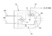
図2Aはこの発明の第2実施形態の照明装置の構成図を示し、図2Bは上記照明装置のプラグ22の構成を示している。[Second Embodiment]
FIG. 2A shows a configuration diagram of the illumination device according to the second embodiment of the present invention, and FIG. 2B shows a configuration of the
図2Aに示すように、コンセント21の差込部25に入力端子33a,33b(図2Bに示す)が差し込まれるプラグ22と、上記プラグ22の出力端子に接続された照明用LED部23とを備えている。上記照明用LED部23は、同一方向に直列に接続された複数の発光ダイオードLED1〜LEDn(例えば直列25灯)を有する。上記照明用LED部23の直列に接続された発光ダイオードLED1〜LEDnの両端を、プラグ22の第1,第2出力端子34a,34b(図2Bに示す)に接続している。上記プラグ22に制御信号線24を介してオンオフ信号が入力される。 As shown in FIG. 2A, a
また、図2Bに示すように、プラグ22に照明用LED部3を駆動する駆動回路30が内蔵されている。上記プラグ22の駆動回路30は、交流電圧を直流電圧に変換する整流器の一例としてのダイオードブリッジ31と、上記ダイオードブリッジ31により変換された直流電圧をオンオフするソリッドステートリレー(SSR)32と、上記照明用LED部23の駆動電流を制限するための抵抗Rとを有している。 Further, as shown in FIG. 2B, a
図2Aに示すように、上記交流電源20の一端をコンセント21の第1電源接続端子(図示せず)に接続し、交流電源20の他端をコンセント21の第2電源接続端子(図示せず)に接続している。 As shown in FIG. 2A, one end of the
また、図2Bに示すように、プラグ22の第1入力端子33aをダイオードブリッジ31の一方の入力端子に接続し、第2入力端子16をダイオードブリッジ31の他方の入力端子に接続している。上記ダイオードブリッジ31の正極側端子をソリッドステートリレー32の入力端子に接続し、ソリッドステートリレー12の出力端子を第1出力端子34aの一方に接続している。また、上記ダイオードブリッジ31の負極側端子と第2出力端子34bとの間を抵抗R2を介して接続している。 2B, the
上記プラグ22のソリッドステートリレー32の制御入力端子に、オンオフ制御のためのオンオフ信号を外部から入力する。このオンオフ信号に基づいてソリッドステートリレー32をオンオフして、照明用LED部23が点灯,非点灯する。 An on / off signal for on / off control is input from the outside to the control input terminal of the
なお、上記プラグ22のソリッドステートリレー32の制御入力端子に、調光制御のためのパルス幅変調信号を外部から入力してもよい。このパルス幅変調信号に基づいてソリッドステートリレー32をオンオフして、照明用LED部23を調光する。 Note that a pulse width modulation signal for dimming control may be input from the outside to the control input terminal of the
上記構成の照明装置によれば、プラグ22に内蔵された駆動回路30のダイオードブリッジ31により、コンセント21の差込部25からの交流電圧を直流電圧に変換する。そして、上記ダイオードブリッジ31により変換された直流電圧は、ソリッドステートリレー32と抵抗R2を介してプラグ22の第1,第2出力端子34a,34bに出力され、プラグ22の第1,第2出力端子34a,34bを介して照明用LED部23に印加される。ここで、ソリッドステートリレー32をオンオフすることにより、照明用LED部23の発光,非発光を制御する。 According to the illuminating device having the above configuration, the AC voltage from the plug-in
このように、プラグ22に照明用LED部23を駆動する駆動回路30を内蔵することにより、回路構成が複雑で部品点数が多いAC/DCコンバータなどを用いることなく、低コストで小型化や軽量化が容易にできる。 Thus, by incorporating the
また、上記プラグ22の信号接続端子35に入力されたオンオフ信号に基づいて、ソリッドステートリレー32をオンオフすることによって、照明用LED部23の発光,非発光の容易に制御することができる。 Further, by turning on / off the solid-
また、上記プラグ22の信号接続端子35に入力されたパルス幅変調信号に基づいて、ソリッドステートリレー32をオンオフすることによって、照明用LED部23の調光を容易に行うことができる。 Further, the lighting LED unit 23 can be easily dimmed by turning on / off the
上記第2実施形態では、1つのプラグ22に1つの駆動回路30を内蔵した場合について説明したが、第1実施形態と同様に、1つのプラグに複数の駆動回路を内蔵してもよい。上記プラグ22に複数の駆動回路を内蔵することによって、駆動回路毎に照明用LED部を接続して、各照明用LED部を制御することが可能となる。これにより、設置性に優れたイルミネーション用の照明装置が可能になる。 Although the case where one
また、1つの駆動回路を内蔵したプラグを複数用いて、コンセントに、波長の異なるLED(例えば赤(R)緑(G)青(B)の三色)からなる照明用LED部が接続されたプラグの入力端子に接続して、プラグ毎にオンオフ信号やパルス幅変調信号により制御することによって、照明の色彩を広範囲に調整することができ、イルミネーション用途にも使用できる。 In addition, using a plurality of plugs incorporating a single drive circuit, an illumination LED unit composed of LEDs of different wavelengths (for example, three colors of red (R), green (G), and blue (B)) is connected to an outlet. By connecting to the input terminal of the plug and controlling each plug with an on / off signal or a pulse width modulation signal, the color of the illumination can be adjusted over a wide range, and it can be used for illumination purposes.
あるいは、1つのプラグに複数の駆動回路を内蔵した構成において、各駆動回路に、波長の異なるLED(例えば赤(R)緑(G)青(B)の三色)からなる照明用LED部を接続して、駆動回路毎にオンオフ信号やパルス幅変調信号により制御することによって、照明の色彩を変えることができ、イルミネーション用途にも使用できる。 Or, in a configuration in which a plurality of drive circuits are built in one plug, each drive circuit is provided with an LED unit for illumination composed of LEDs having different wavelengths (for example, three colors of red (R), green (G), and blue (B)). By connecting and controlling each drive circuit with an on / off signal or a pulse width modulation signal, the color of illumination can be changed, and it can be used for illumination purposes.
上記第1,第2実施形態では、整流器としてダイオードブリッジ11,31を用いたが、整流器はこれに限らず、半波整流回路などを用いた他の構成の整流器を用いてもよい。 In the first and second embodiments, the diode bridges 11 and 31 are used as the rectifier. However, the rectifier is not limited to this, and a rectifier having another configuration using a half-wave rectifier circuit or the like may be used.
この発明の具体的な実施の形態について説明したが、この発明は上記第1,第2実施形態に限定されるものではなく、この発明の範囲内で種々変更して実施することができる。 Although specific embodiments of the present invention have been described, the present invention is not limited to the first and second embodiments described above, and various modifications can be made within the scope of the present invention.
1,21…コンセント
2,22…プラグ
3,23…照明用LED部
11,31…ダイオードブリッジ
12,32…ソリッドステートリレー
13,25…差込部
13a,13b…接続端子
14,24…制御信号線
15…第1電源接続端子
16…第2電源接続端子
LED1〜LEDn…発光ダイオード
33a…第1入力端子
33b…第2入力端子
34a…第1出力端子
34b…第2出力端子DESCRIPTION OF
Claims (12)
Translated fromJapanese上記照明用LED部が出力端子に接続されたプラグと、
上記プラグの入力端子が差込部の接続端子に接続され、上記照明用LED部を駆動する駆動回路が内蔵されたコンセントと
を備え、
上記駆動回路は、
交流電源からの交流電圧を直流電圧に変換する整流器と、
上記整流器により変換された直流電圧をオンオフするソリッドステートリレーと、
上記ソリッドステートリレーの出力端子と上記差込部の接続端子との間に接続された抵抗と
を有することを特徴とする照明装置。An LED unit for illumination;
A plug in which the LED unit for illumination is connected to an output terminal;
An input terminal of the plug is connected to a connection terminal of the plug-in portion, and includes an outlet having a built-in drive circuit for driving the lighting LED unit,
The drive circuit is
A rectifier that converts AC voltage from an AC power source into DC voltage;
A solid state relay that turns on and off the DC voltage converted by the rectifier;
A lighting device comprising: a resistor connected between an output terminal of the solid state relay and a connection terminal of the plug-in portion.
上記コンセントの信号接続端子に入力されたオンオフ信号に基づいて、上記ソリッドステートリレーがオンオフすることを特徴とする照明装置。The lighting device according to claim 1.
The lighting device, wherein the solid state relay is turned on and off based on an on / off signal input to a signal connection terminal of the outlet.
上記コンセントの信号接続端子に入力されたパルス幅変調信号に基づいて、上記ソリッドステートリレーがオンオフすることを特徴とする照明装置。The lighting device according to claim 1.
The lighting device, wherein the solid state relay is turned on and off based on a pulse width modulation signal input to a signal connection terminal of the outlet.
上記コンセントに上記駆動回路が複数内蔵されていることを特徴とする照明装置。In the illuminating device as described in any one of Claim 1 to 3,
A lighting device comprising a plurality of the drive circuits built in the outlet.
上記プラグは複数あり、
上記複数のプラグの上記出力端子に接続された上記照明用LED部は夫々、発光波長の異なるLEDが用いられ、
上記コンセントの上記差込部に、上記複数の駆動回路に対応する上記接続端子を夫々設けて、上記差込部の各接続端子に上記複数のプラグの入力端子を接続したことを特徴とする照明装置。The lighting device according to claim 4.
There are multiple plugs,
Each of the lighting LED parts connected to the output terminals of the plurality of plugs uses LEDs having different emission wavelengths,
The lighting device is characterized in that the plug terminal of the outlet is provided with the connection terminals corresponding to the plurality of drive circuits, and the input terminals of the plugs are connected to the connection terminals of the plug section. apparatus.
上記複数の照明用LED部は、赤色と緑色と青色の発光波長の異なる3種類のLEDが用いられていることを特徴とする照明装置。The lighting device according to claim 5.
The lighting device, wherein the plurality of LED units for illumination use three types of LEDs having different emission wavelengths of red, green, and blue.
上記照明用LED部が出力端子に接続され、上記照明用LED部を駆動する駆動回路が内蔵されたプラグと
を備え、
上記駆動回路は、
上記プラグの入力端子が差し込まれたコンセントの差込部からの交流電圧を直流電圧に変換する整流器と、
上記整流器により変換された直流電圧をオンオフするソリッドステートリレーと、
上記ソリッドステートリレーの出力端子と上記プラグの上記出力端子との間に接続された抵抗と
を有することを特徴とする照明装置。An LED unit for illumination;
The lighting LED unit is connected to an output terminal, and includes a plug with a built-in driving circuit for driving the lighting LED unit,
The drive circuit is
A rectifier that converts AC voltage from the outlet of the outlet into which the input terminal of the plug is inserted into DC voltage;
A solid state relay that turns on and off the DC voltage converted by the rectifier;
An illumination device comprising: a resistor connected between an output terminal of the solid state relay and the output terminal of the plug.
上記プラグの信号接続端子に入力されたオンオフ信号に基づいて、上記ソリッドステートリレーがオンオフすることを特徴とする照明装置。The lighting device according to claim 7.
The lighting device, wherein the solid state relay is turned on and off based on an on / off signal input to a signal connection terminal of the plug.
上記プラグの信号接続端子に入力されたパルス幅変調信号に基づいて、上記ソリッドステートリレーがオンオフすることを特徴とする照明装置。The lighting device according to claim 7.
The lighting device, wherein the solid state relay is turned on and off based on a pulse width modulation signal input to a signal connection terminal of the plug.
上記プラグに上記駆動回路が複数内蔵されていることを特徴とする照明装置。In the illuminating device as described in any one of Claim 7-9,
A lighting device comprising a plurality of the drive circuits built in the plug.
上記プラグに、上記複数の駆動回路に対応する上記出力端子を夫々設けて、上記各出力端子に、発光波長の異なるLEDが夫々用いられた複数の上記照明用LED部が接続されていることを特徴とする照明装置。The lighting device according to claim 10.
The plug is provided with the output terminals corresponding to the plurality of drive circuits, respectively, and the plurality of illumination LED units each using LEDs having different emission wavelengths are connected to the output terminals. A lighting device.
上記複数の照明用LED部は、赤色と緑色と青色の発光波長の異なる3種類のLEDが夫々用いられていることを特徴とする照明装置。The lighting device according to claim 11.
The plurality of LED units for illumination use three types of LEDs having different emission wavelengths of red, green and blue, respectively.
Priority Applications (1)
| Application Number | Priority Date | Filing Date | Title |
|---|---|---|---|
| JP2008022877AJP2009181950A (en) | 2008-02-01 | 2008-02-01 | Lighting device |
Applications Claiming Priority (1)
| Application Number | Priority Date | Filing Date | Title |
|---|---|---|---|
| JP2008022877AJP2009181950A (en) | 2008-02-01 | 2008-02-01 | Lighting device |
Publications (1)
| Publication Number | Publication Date |
|---|---|
| JP2009181950Atrue JP2009181950A (en) | 2009-08-13 |
Family
ID=41035733
Family Applications (1)
| Application Number | Title | Priority Date | Filing Date |
|---|---|---|---|
| JP2008022877APendingJP2009181950A (en) | 2008-02-01 | 2008-02-01 | Lighting device |
Country Status (1)
| Country | Link |
|---|---|
| JP (1) | JP2009181950A (en) |
Cited By (2)
| Publication number | Priority date | Publication date | Assignee | Title |
|---|---|---|---|---|
| JP2012028505A (en)* | 2010-07-22 | 2012-02-09 | Shindengen Electric Mfg Co Ltd | Led lighting device |
| JP2013504285A (en)* | 2009-09-01 | 2013-02-04 | コーニンクレッカ フィリップス エレクトロニクス エヌ ヴィ | Power supply system for electronic load |
- 2008
- 2008-02-01JPJP2008022877Apatent/JP2009181950A/enactivePending
Cited By (3)
| Publication number | Priority date | Publication date | Assignee | Title |
|---|---|---|---|---|
| JP2013504285A (en)* | 2009-09-01 | 2013-02-04 | コーニンクレッカ フィリップス エレクトロニクス エヌ ヴィ | Power supply system for electronic load |
| KR101759614B1 (en) | 2009-09-01 | 2017-07-25 | 필립스 라이팅 홀딩 비.브이. | Power supply system for electronic loads |
| JP2012028505A (en)* | 2010-07-22 | 2012-02-09 | Shindengen Electric Mfg Co Ltd | Led lighting device |
Similar Documents
| Publication | Publication Date | Title |
|---|---|---|
| JP5725736B2 (en) | LED power supply device and LED lighting apparatus | |
| US20110025230A1 (en) | Driver device for leds | |
| US20040004446A1 (en) | Drive circuit for an led lighting apparatus | |
| KR101648788B1 (en) | LED emotional lighting luminaire using both of correlated color temperature control and luminous flux control apparatus | |
| US11612029B2 (en) | Controllable lighting device | |
| JP2012004240A (en) | Led power supply and led illumination equipment | |
| TW201538030A (en) | Light adjustable AC LED device | |
| JP2014143307A (en) | Light-emitting module and luminaire | |
| JP5454189B2 (en) | Power supply circuit and lighting device | |
| CN106163021A (en) | Illuminator | |
| US11140759B2 (en) | Method of multi-mode color control by an LED driver | |
| JP2009181950A (en) | Lighting device | |
| KR20100016676A (en) | Lighting device with led | |
| JP5032933B2 (en) | LED lighting device | |
| JP2009016493A (en) | Led light emitting device | |
| US12048074B2 (en) | Light emitting diode, LED, based lighting device arranged for emitting a particular emitted light following a Planckian locus in a color space | |
| JP2010009783A (en) | Lighting fixture | |
| KR102826177B1 (en) | Smart lighting system using dual LED | |
| EP4316207B1 (en) | Method of multi-mode color control by an led driver | |
| KR102858877B1 (en) | LED driving circuit for variable color temperature of LED module with enhanced color temperature change characteristics in low current section | |
| TWI450639B (en) | Methods and apparatus for driving led-based lighting units | |
| KR20100010184U (en) | LED lamp for having socket unit embedding driving circuit | |
| CN108337762B (en) | Control circuit and LED lighting device | |
| CN114303443A (en) | Light emitting diode, LED, based current splitter for splitting LED current between multiple LED channels and multi-channel light emitting diode, LED, based lighting device | |
| JP6489472B2 (en) | Power supply device and lighting device |