JP2009176213A - Network boot system - Google Patents
Network boot systemDownload PDFInfo
- Publication number
- JP2009176213A JP2009176213AJP2008016330AJP2008016330AJP2009176213AJP 2009176213 AJP2009176213 AJP 2009176213AJP 2008016330 AJP2008016330 AJP 2008016330AJP 2008016330 AJP2008016330 AJP 2008016330AJP 2009176213 AJP2009176213 AJP 2009176213A
- Authority
- JP
- Japan
- Prior art keywords
- data
- information processing
- machine monitor
- network
- storage server
- Prior art date
- Legal status (The legal status is an assumption and is not a legal conclusion. Google has not performed a legal analysis and makes no representation as to the accuracy of the status listed.)
- Pending
Links
- 238000000034methodMethods0.000claimsabstractdescription21
- 230000010365information processingEffects0.000claimsdescription23
- 230000008569processEffects0.000claimsdescription12
- 230000004913activationEffects0.000claimsdescription10
- 238000012544monitoring processMethods0.000claimsdescription9
- 238000003672processing methodMethods0.000claimsdescription3
- KKIMDKMETPPURN-UHFFFAOYSA-N1-(3-(trifluoromethyl)phenyl)piperazineChemical compoundFC(F)(F)C1=CC=CC(N2CCNCC2)=C1KKIMDKMETPPURN-UHFFFAOYSA-N0.000abstractdescription7
- 238000013507mappingMethods0.000abstract1
- 238000010586diagramMethods0.000description5
- 230000006870functionEffects0.000description5
- 230000008859changeEffects0.000description3
- 238000010276constructionMethods0.000description2
- 230000007246mechanismEffects0.000description2
- 230000004044responseEffects0.000description2
- 210000000554irisAnatomy0.000description1
- 230000003287optical effectEffects0.000description1
- 210000003462veinAnatomy0.000description1
Images


Landscapes
- Stored Programmes (AREA)
Abstract
Description
Translated fromJapanese本発明は、情報処理装置、情報処理方法、及び情報処理システム、並びにプログラムに関し、例えば、OSデータを含む論理的ディスクボリュームを管理するストレージサーバにネットワーク経由でアクセスすることにより実行される情報処理に関するものである。 The present invention relates to an information processing apparatus, an information processing method, an information processing system, and a program. For example, the present invention relates to information processing executed by accessing a storage server that manages a logical disk volume including OS data via a network. Is.
従来、ネットワーク先のOS配信サーバにあるOSイメージをネットワーク経由でブートする方式として代表的なものに、PXE(Preboot Execution Environment)に対応したネットワークカードとDHCPサーバ、及びTFTPサーバを利用したネットワークブート方式がある。 Conventionally, a network boot method using a network card corresponding to PXE (Preboot Execution Environment), a DHCP server, and a TFTP server is a typical method for booting an OS image on an OS distribution server at a network destination via a network. There is.
この方式においては、PXE ROMを搭載したネットワークカードを利用者端末に配備し、起動時にBIOSからPXE ROMに制御が移った後、ROM内のプログラムがDHCPサーバからIPアドレスを取得し、TFTPサーバからブート用のブートストラップと呼ばれるコードをダウンロードする。そして、そのダウンロードしたブートストラップを使ってOSイメージをTFTPサーバからダウンロードし、起動する。このような仕組みを利用したネットワークブートとその起動の高速化については、例えば、特許文献1に開示されているものがある。 In this method, a network card equipped with a PXE ROM is arranged in the user terminal, and after the control is transferred from the BIOS to the PXE ROM at startup, the program in the ROM acquires an IP address from the DHCP server, and from the TFTP server. Download code called bootstrap for booting. Then, using the downloaded bootstrap, the OS image is downloaded from the TFTP server and activated. For example, Patent Document 1 discloses a network boot using such a mechanism and speeding up the startup.
しかしながら、特許文献1の方式の場合、ネットワークカードとして特別なPXE ROMを搭載したものが必要になってくる。 However, in the case of the method of Patent Document 1, a network card equipped with a special PXE ROM is required.
また、BIOSをネットワーク対応のものとして設定しなければならない。 Also, the BIOS must be set as network compatible.
さらに、DHCPサーバやTFTPサーバを構築する必要があり、DHCPサーバでIPアドレスを取得する方式に変更しなければならず、ネットワークの構成・設定を従来のものから大幅に変更する必要がある。また、DHCPサーバはルータとはレイヤが異なるため、ネットワークセグメント(ルータ)を越えて別のネットワークと共通のものとして構築することができない。つまり、セグメント毎にそれぞれDHCPサーバ及びTFTPサーバを設ける必要がある。 Furthermore, it is necessary to construct a DHCP server or a TFTP server, and it is necessary to change to a method in which an IP address is acquired by the DHCP server, and it is necessary to greatly change the network configuration / setting from the conventional one. Also, since the DHCP server has a different layer from the router, it cannot be constructed as a common network with another network across the network segment (router). That is, it is necessary to provide a DHCP server and a TFTP server for each segment.
したがって、特許文献1に示される方式を既存のシステムに対して導入するには敷居が高く、コストも掛かってしまう。 Therefore, introducing the method disclosed in Patent Document 1 into an existing system is expensive and costly.
本発明はこのような状況に鑑みてなされたものであり、特殊なネットワークカードやネットワーク構成がなくても、ネットワークブートできる方式を実現するものである。 The present invention has been made in view of such a situation, and realizes a system capable of network booting without a special network card or network configuration.
上記課題を解決するために、IPネットワーク経由でデバイスへのI/Oコマンドを発行して、ネットワーク経由でデバイスアクセスを実現するプロトコル、例えばiSCSIプロトコルを用いてOSイメージ(OSデータ)をストレージサーバから取得してPC内にマウントしてブートしている。iSCSIプロトコルを用いることにより、ルータとサーバ(DHCPサーバ)のレイヤの相違による、ルータ越えが不可能になるという従来の不都合を改善している。また、PC内に仮想マシン、管理用仮想マシン、仮想マシンモニタを設け、各処理部を仮想化している。 In order to solve the above problem, an OS image (OS data) is issued from a storage server by issuing an I / O command to a device via an IP network and using a protocol for realizing device access via the network, for example, an iSCSI protocol. Obtained, mounted in the PC and booted. By using the iSCSI protocol, the conventional inconvenience that it is impossible to cross the router due to a difference in layer between the router and the server (DHCP server) is improved. Further, a virtual machine, a management virtual machine, and a virtual machine monitor are provided in the PC to virtualize each processing unit.
即ち、本発明による情報処理装置は、OSデータ(OSイメージ)を含む論理的ディスクボリュームを管理するストレージサーバにネットワーク経由でアクセスする情報処理装置である。この情報処理装置は、アプリケーションを実行するアプリケーションデータ処理手段(仮想マシン)と、装置内で実行しようとする処理をモニタし、分析するマシンモニタ手段(仮想マシンモニタ)と、マシンモニタ手段上で稼動し、iSCSIプロトコルを用いて、マシンモニタ手段と協働してストレージサーバにアクセスし、論理的ディスクボリュームを取得するデータ取得処理手段(管理用仮想マシン内のiSCSIマウントモジュール)と、マシンモニタ手段上で稼動し、マシンモニタ手段と協働して、論理的ディスクボリュームに含まれるOSデータを、アプリケーションデータ処理手段において起動させるOS起動手段(管理用仮想マシン内の仮想マシン起動モジュール)と、を備えている。ここで、アプリケーションデータ処理部と、マシンモニタ手段と、データ取得処理手段と、OS起動手段は、情報処理装置内において仮想化されている。 That is, the information processing apparatus according to the present invention is an information processing apparatus that accesses a storage server that manages a logical disk volume including OS data (OS image) via a network. This information processing apparatus operates on an application data processing means (virtual machine) for executing an application, a machine monitor means (virtual machine monitor) for monitoring and analyzing a process to be executed in the apparatus, and a machine monitor means Then, using the iSCSI protocol, the data acquisition processing means (iSCSI mount module in the management virtual machine) that accesses the storage server in cooperation with the machine monitoring means and acquires the logical disk volume, and the machine monitoring means And OS activation means (virtual machine activation module in the management virtual machine) that activates the OS data contained in the logical disk volume in the application data processing means in cooperation with the machine monitor means. ing. Here, the application data processing unit, the machine monitor unit, the data acquisition processing unit, and the OS activation unit are virtualized in the information processing apparatus.
また、データ取得手段は、ユーザ認証処理が完了した後に、ストレージサーバにアクセスする。 The data acquisition unit accesses the storage server after the user authentication process is completed.
さらに、OSデータは、印刷許可・禁止を制御する印刷制御手段(印刷制御モジュール)と、外部媒体へのデータの書出し制御する外部媒体書出し制御手段(外部媒体アクセス制御モジュール)と、端末制御手段(端末制御サービス)を含んでいる。そして、データ取得処理手段は、OSデータによって可能な動作を規定するセキュリティポリシを管理するポリシデータベースにアクセスし、OSデータがアプリケーションデータ処理手段に導入された後、端末制御手段が、印刷制御手段と外部媒体書出し制御手段にセキュリティポリシを反映する。 Furthermore, the OS data includes a print control unit (print control module) that controls printing permission / prohibition, an external medium writing control unit (external medium access control module) that controls writing data to an external medium, and a terminal control unit ( Terminal control service). Then, the data acquisition processing unit accesses a policy database that manages a security policy that defines an operation that can be performed by the OS data. After the OS data is introduced into the application data processing unit, the terminal control unit and the print control unit The security policy is reflected in the external medium writing control means.
さらなる本発明の特徴は、以下本発明を実施するための最良の形態および添付図面によって明らかになるものである。 Further features of the present invention will become apparent from the best mode for carrying out the present invention and the accompanying drawings.
本発明によれば、特殊なネットワークカードやネットワーク構成がなくても、コストを抑えつつ、ネットワークブートできる方式を実現できるようになる。 According to the present invention, it is possible to realize a system capable of network booting while suppressing costs even without a special network card or network configuration.
本発明では、利用者端末上で仮想マシンモニタを起動し、管理用OSを立ち上げてそのOSよりストレージサーバにアクセスし、ストレージサーバ上にあるボリュームをマウントし、そのボリュームにインストールされたOSを別の仮想マシン上に起動する。このようにすることにより、PXE対応のネットワークカードを利用せずに、通常のネットワークカードとネットワーク構成において、ストレージサーバで管理されたOSイメージをネットワーク経由でブートすることができる。 In the present invention, the virtual machine monitor is started on the user terminal, the management OS is started, the storage server is accessed from the OS, the volume on the storage server is mounted, and the OS installed on the volume is installed. Start on another virtual machine. By doing so, it is possible to boot an OS image managed by the storage server via the network in a normal network card and network configuration without using a PXE-compatible network card.
以下、添付図面を参照して本発明の実施形態について説明する。ただし、本実施形態は本発明を実現するための一例に過ぎず、本発明の技術的範囲を限定するものではないことに注意すべきである。また、各図において共通の構成については同一の参照番号が付されている。 Hereinafter, embodiments of the present invention will be described with reference to the accompanying drawings. However, it should be noted that this embodiment is merely an example for realizing the present invention, and does not limit the technical scope of the present invention. In each drawing, the same reference numerals are assigned to common components.
(1)第1の実施形態
<システム構成>
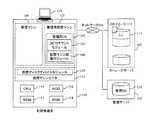
図1は、本発明の第1の実施形態おけるネットワークブートシステムの概略構成を示す図である。(1) First Embodiment <System Configuration>
FIG. 1 is a diagram showing a schematic configuration of a network boot system in the first embodiment of the present invention.
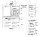
ネットワークブートシステムは、利用者端末101と、ストレージサーバ102と、管理サーバ103と、を備え、それらがネットワーク104で互いに接続された構成となっている。 The network boot system includes a
ストレージサーバ102は、iSCSIストレージサーバであり、iSCSIプロトコルを用いて、ストレージサーバ内のLU(Logical Unit)113にアクセスすることができるようになっている。このように、本発明では、DHCPプロトコルを用いず、iSCSIプロトコルを用いているので、利用者端末101は、ルータ(図示せず)を越えてストレージサーバにアクセスできるようになっている。つまり、セグメントの制限がない。また、LU113は各利用者に対応しており、利用者ごとに設定されたOSとアプリケーションを含むOSイメージ112が各LU113にインストールされている。ここで、OSイメージ112はWindows(登録商標)としているが、Linux等、他のOSでも本発明は適用可能である。 The
利用者端末101は、CPU(中央処理部)115と、HDD(ハードディスクドライブ)116と、ROM(Read Only Memory)117と、RAM(Random Access Memory)118と、表示装置119と、を備えている。さらに、利用者端末101には、仮想マシンモニタ111がインストールされており、その上に管理用仮想マシン105と通常の仮想マシン109がある。管理用仮想マシン105には管理用OS106がインストールされており、その上にiSCSIマウントモジュール107が稼動している。 The
ここで、仮想マシンモニタ111は、利用者端末のハードウェアリソースを仮想化することで、複数のOSを同時に実行できる環境を提供するソフトウェアである。代表的なものとして、オープンソースソフトウェアのXenがあり、本発明でもその利用を想定している。管理用仮想マシン105は、仮想マシンモニタ111が起動したとき、最初に起動される仮想マシンであり、その上でLinuxやWindows(登録商標) Embedded等の軽量なOSが稼動する。仮想マシンモニタ111には、各仮想マシンが起動の対象とする仮想的なディスクデバイスが実装されているが、仮想ディスクデバイスモジュール110は、ある仮想マシン109の起動ディスクとなる仮想ディスクデバイスを実装するモジュールである。 Here, the
仮想ディスクデバイスモジュール110とiSCSIマウントモジュール107は、連携(協働)して動作する。つまり、iSCSIマウントモジュール107は、仮想ディスクデバイスモジュール110を経由して、OSイメージサーバ112の対応するLU113から取得し、自身(iSCSIマウントモジュール107)にマウントしたLU113へのポインタを保持する。そして、仮想ディスクデバイスモジュール110の作成する仮想ディスクデバイスがiSCSIマウントモジュール107に保持されたポインタを用いて、LU113を参照するようになっている。 The virtual
また、仮想マシン起動モジュール108は、仮想ディスクデバイスモジュール110がLU113への参照を生成完了したタイミングで、仮想マシン109を起動するモジュールである。 The virtual
管理サーバ103は、管理DB114(図2参照)を格納したサーバである。利用者端末101の電源をONにした後、iSCSIマウントモジュールがアクセスした際に、入力されたID・パスワードが管理サーバ103に送信される。そして、そのID・パスワードをキーとして管理DB114より検索が実行され、利用者に対応するLU113の識別番号であるLU番号をiSCSIマウントモジュール107に返す。この管理サーバにより、利用者のユーザ認証を行い、適切なOSイメージ配信を行うための対応するLU113を、利用者端末101に通知する。本実施形態では、利用者認証の手段としてID・パスワードとしたが、指紋や静脈、虹彩等の生態情報や、ICカード等のハードウェアトークンに格納された証明書、ワンタイムパスワード等を使用しても良い。なお、ここでは管理DB114はストレージサーバ102とは別の管理サーバ103に設置されているが、ストレージサーバ102内に設置しても良い。 The
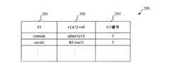
<管理DBの内容>
図2は、管理DB114に格納されたLU管理テーブル200の構成を示す図である。LU管理テーブル200の属性として、ID201、パスワード202、LU番号203がある。これは、各利用者に対応するIDとパスワード、及びLU番号の組み合わせを記録するテーブルであり、利用者認証にも使用される。<Contents of management DB>
FIG. 2 is a diagram showing the configuration of the LU management table 200 stored in the
利用者端末101が起動されると、iSCSIマウントモジュール107が利用者に例えばID及びパスワードの入力を促し、入力されたID及びパスワードが管理サーバ103に送信される。そして、管理サーバ103では、送信されてきたID及びパスワードに対応するLU番号203がiSCSIマウントモジュール107に返送される。このLU番号203は、ストレージサーバ102に格納されているLU113の番号に相当するものである。 When the
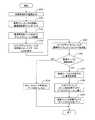
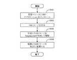
<OSブート時の処理>
図3は、OSブート時の処理、つまり、ブート電源を入れ、OSを起動するまでの処理を説明するためのフローチャートである。なお、仮想マシン109、管理用仮想マシン105、仮想マシンモニタ111は、実際にはファイルとして利用者端末101にインストールされており、動作する場合には、中央処理部(CPU)115が各ファイルを読み込んで対応する処理を実行する。<Processing at OS boot>
FIG. 3 is a flowchart for explaining processing at the time of booting the OS, that is, processing from turning on boot power to starting up the OS. Note that the
図3において、まず、利用者が利用者端末の電源をONにすると、中央処理部115がそれを検知して利用者端末101を起動する(ステップS301)。利用者端末101が起動されると、仮想マシンモニタ111が起動し、管理用仮想マシン105をブート(使用できる状態に)する(ステップS302)。このとき、管理用仮想マシン105がブート時に起動されるよう管理用OS106上に設定されたiSCSIマウントモジュール107を起動させる(ステップS303)。 In FIG. 3, first, when the user turns on the power of the user terminal, the
続いて、iSCSIマウントモジュール107は、起動時に利用者にID・パスワードを要求する(ステップS304)。利用者がID・パスワードを入力した後、iSCSIマウントモジュール107は、仮想マシンモニタ111経由で管理サーバ103にID・パスワードを送信する(ステップS305)。 Subsequently, the
管理サーバ103は、管理DB114にアクセスして、ID・パスワードが登録されているかを照合することで、利用者認証を行う(ステップS306)。認証に失敗した場合は、iSCSIマウントモジュール107に認証失敗結果を通知し、その結果を受けてエラーメッセージを利用者端末101の表示装置119に表示し、ブート処理のキャンセルを行う(ステップS310)。 The
認証に成功した場合、管理サーバ103は、対応するLU番号203をiSCSIマウントモジュール107に通知する(ステップS307)。iSCSIマウントモジュール107は、取得したLU番号203を基に、ストレージサーバ102にiSCSIプロトコルでアクセスして、対応するLU113を自身(iSCSIマウントモジュール107)にマウントし、LU113にアクセスするためのポインタを仮想ディスクデバイスモジュール110に引き渡す(ステップS308)。その後、仮想マシン起動モジュール108が仮想マシン109を起動し、マウントされたLU203を仮想ディスクとして利用可能な仮想ディスクデバイスモジュール110から対応するOSイメージを取得し、OSをブートする(ステップS309)。 If the authentication is successful, the
以上のアーキテクチャを採ることにより、ストレージサーバ102に保管されたLU113上のOSイメージ112を、特殊なネットワークカード等のハードウェアを使う必要なく、iSCSIプロトコルを用いてネットワークブートすることができる。特殊なネットワークカードを使う必要がなく、ネットワーク構成を変更する必要がないため、導入するための敷居が低く、導入しやすい点が大きなメリットである。 By adopting the above architecture, the OS image 112 on the
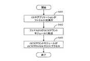
<ファイルI/O時の処理>
図4は、仮想マシン109におけるファイルI/O時の処理を説明するためのフローチャートである。仮想マシン109上で稼動中のOS(ストレージサーバ102から取得したOS)やアプリケーションがファイルI/O要求を発行すると(ステップS401)、ファイルI/O要求は仮想ディスクデバイスモジュール110経由で、iSCSIマウントモジュール107に転送される(ステップS402)。iSCSIマウントモジュール107は、受け取ったファイルI/O要求から、iSCSIプロトコルでストレージサーバ102にアクセスするためのIPパケットを生成して、LU113にアクセスする(ステップS403)。これにより、ファイルI/OがLU113へのアクセスに変換される。このようにして、LU113からブートされたOSの他に必要なデータがLU113からその都度取得されるようになっている。<Process during file I / O>
FIG. 4 is a flowchart for explaining processing at the time of file I / O in the
<OSイメージ構築処理>
図5は、システム管理者がOSイメージを構築する際の処理を説明するためのフローチャートである。ここで、OSイメージは、例えばWindows(登録商標)とする。なお、ここで言及する管理者端末の構成は利用者端末101と同様のものである。<OS image construction processing>
FIG. 5 is a flowchart for explaining processing when the system administrator constructs an OS image. Here, the OS image is, for example, Windows (registered trademark). Note that the configuration of the administrator terminal referred to here is the same as that of the
まず、管理者によって管理者端末(図示せず)の仮想マシン上にOSとアプリケーションがインストールされる(ステップS501)。そして、管理者端末における仮想ハードディスクに構築されたバイナリデータが管理者によって複製されてOSイメージが作成される(ステップS502)。 First, an OS and an application are installed on a virtual machine of an administrator terminal (not shown) by an administrator (step S501). Then, the binary data constructed on the virtual hard disk in the administrator terminal is copied by the administrator to create an OS image (step S502).
その作成されたOSイメージをベースとしてSysprep.exeを用いて中央処理部がOSイメージを複製する(ステップS503)。こうして複製されたOSイメージは、それぞれ固有のセキュリティIDが付与される。このため、同一ドメイン内におけるセキュリティIDの衝突を避けることができる。中央処理部は、この複製したOSイメージを各LU113に配置し(ステップS504)、ストレージサーバ102における各LUの初期化を実行することができる。 Based on the created OS image, Sysprep. The central processing unit duplicates the OS image using exe (step S503). Each OS image copied in this way is given a unique security ID. For this reason, collision of security IDs in the same domain can be avoided. The central processing unit can place the copied OS image in each LU 113 (step S504) and execute initialization of each LU in the
(2)第2の実施形態
<システム構成>
図6は、第2の実施形態によるネットワークブートシステムであって、第1の実施形態によるネットワークブート方式を応用した、ネットワークブート型シンクライアントシステムの概略構成を示す図である。(2) Second embodiment <System configuration>
FIG. 6 is a diagram illustrating a schematic configuration of a network boot type thin client system to which the network boot system according to the first embodiment is applied, which is a network boot system according to the second embodiment.
利用者端末101、ストレージサーバ102、および管理サーバ103の構成は、図1で示されるネットワークブートシステムにおける構成と同様である。 The configurations of the
図6において、ポリシ管理サーバ601は、利用者端末101上の仮想マシン109でブートしたOSイメージ112のセキュリティ制御を司る管理サーバである。ポリシ管理サーバ601にはポリシDB602が格納されており、各OSイメージ112に対するポリシ設定が保存されている。そして、利用者端末101でブートされたOSイメージは、このポリシ設定の下に、外部媒体への保存や印刷に関して利用制限がかけられる。 In FIG. 6, a
なお、管理DB114及びポリシDB602はストレージサーバ102とは別の管理サーバ103及びポリシ管理サーバ601にそれぞれ設置されているが、ストレージサーバ102内に集約しても良い。 The
<OSイメージの構成>
図7は、LU113に格納されたOSイメージ112の構成図である。OSイメージ112は、OS701内に一般利用するアプリケーション702と、端末制御サービス703と、印刷制御モジュール704と、外部媒体アクセス制御モジュール705と、を備える構成となっている。<Configuration of OS image>
FIG. 7 is a configuration diagram of the OS image 112 stored in the
端末制御サービス703は、OS701の起動時に起動され、OS701のシャットダウンまで稼動し続ける。また、端末制御サービス703は、起動時にポリシ管理サーバ601にアクセスして、OSのセキュリティIDをキーとしてポリシ管理サーバ601に送信し、対応するセキュリティポリシ設定(図8参照)を取得する。端末制御サービス703は、取得したセキュリティポリシ設定を基に、印刷制御モジュール704、及び外部媒体アクセス制御モジュール705にコマンドを投げ、ポリシに対応したセキュリティを設定する。 The
外部媒体アクセス制御モジュール705は、USBメモリ等の外部媒体やDVD−RやCD−R等の備え付けデバイスに対する書込み制御や暗号化書出しを行うモジュールである。また、印刷制御モジュール704は、印刷の許可・不許可を制御するモジュールである。これら2つのモジュールは、端末制御サービス703から取得したポリシ設定800に応じて、印刷制御や媒体への書出し制御を行う。 The external medium
<セキュリティポリシ管理テーブル>
図8は、ポリシDBに格納されたセキュリティポリシ管理テーブル800の構成を示す図である。セキュリティポリシ管理テーブルの属性には、セキュリティID801、印刷制御802、USB書出し803、CD−R書出し804が含まれている。セキュリティID801は、各OSイメージに割り振られた固有のID(図5の説明参照)である。印刷制御802は、印刷の許可・禁止を設定項目として持っている。また、USB書出し803、CD−R書出し804では、USB接続の外部媒体や内蔵CD−R等への書出し許可・禁止、および書出し可能としたときの暗号化書出し、もしくは平文書出しを設定できる。<Security policy management table>
FIG. 8 is a diagram showing the configuration of the security policy management table 800 stored in the policy DB. Attributes of the security policy management table include a
<端末制御サービス起動時の処理>
図9は、端末制御サービスの起動時の処理を説明するためのフローチャートである。まず、中央処理部115は、ブートされたOS701を起動すると同時に、端末制御サービス703を起動する(ステップS901)。次に、端末制御サービス703は、起動された後、OS701のセキュリティIDを取得して、ポリシ管理サーバ601に送信する(ステップS902)。上述にように、セキュリティIDは、OSごとに一意に設定された識別子であり、OSに対応したセキュリティポリシを取得するキーとして利用される。<Processing at terminal control service startup>
FIG. 9 is a flowchart for explaining processing at the time of activation of the terminal control service. First, the
ポリシ管理サーバ601は、セキュリティIDをキーとして、ポリシDB602のセキュリティポリシ管理テーブル800を検索し、対応するポリシを取得する(ステップS903)。 The
続いて、取得したポリシを基に、端末制御サービス703は、印刷制御モジュール704・外部媒体アクセス制御モジュール705にセキュリティポリシに相当するコマンドを送信する(ステップS904)。そのコマンドを受けて、印刷制御モジュール704・外部媒体アクセス制御モジュール705は、ポリシを利用者端末101に反映する(ステップS905)。 Subsequently, based on the acquired policy, the
(3)まとめ
以上で述べたように、本発明の実施形態では、ネットワーク先にあるストレージサーバから、特殊なPXE対応のネットワークカードを利用せず、OSをネットワークブート可能とする仕組みを提供する。つまり、iSCSIプロトコルを用いてOSイメージ(OSデータ)をストレージサーバから取得してPC内にマウントしてブートしている。また、PC内に仮想マシン、管理用仮想マシン、仮想マシンモニタを設け、各処理部を仮想化している。(3) Summary As described above, the embodiment of the present invention provides a mechanism that allows the OS to be network booted from a storage server at a network destination without using a special PXE-compatible network card. That is, the OS image (OS data) is acquired from the storage server using the iSCSI protocol, mounted in the PC, and booted. Further, a virtual machine, a management virtual machine, and a virtual machine monitor are provided in the PC to virtualize each processing unit.
このように、iSCSIプロトコルを用いることにより、ルータとサーバ(DHCPサーバ)のレイヤの相違による、ルータ越えが不可能になるという従来の不都合を改善している。また、仮想化することによりBIOSには依存しなくなるので、従来のようにPXE対応のネットワークカードに付け替えて、DHCPサーバやTFTPサーバを構築する必要がなく、低コストでの導入を可能とする。さらに、本ネットワークブート方式と外部媒体への書込み制御、印刷制御を組み合わせることにより、特殊なネットワークカードの必要がない、ネットワークブート型のシンクライアントを実現することができる。 As described above, the use of the iSCSI protocol improves the conventional inconvenience that it is impossible to cross the router due to the difference in the layers of the router and the server (DHCP server). Further, since it does not depend on the BIOS by virtualization, it is not necessary to replace the network card with PXE and build a DHCP server or a TFTP server as in the prior art, and it can be introduced at a low cost. Further, by combining the network boot method, the write control to the external medium, and the print control, a network boot type thin client that does not require a special network card can be realized.
なお、本発明は、実施形態の機能を実現するソフトウェアのプログラムコードによっても実現できる。この場合、プログラムコードを記録した記憶媒体をシステム或は装置に提供し、そのシステム或は装置のコンピュータ(又はCPUやMPU)が記憶媒体に格納されたプログラムコードを読み出す。この場合、記憶媒体から読み出されたプログラムコード自体が前述した実施形態の機能を実現することになり、そのプログラムコード自体、及びそれを記憶した記憶媒体は本発明を構成することになる。このようなプログラムコードを供給するための記憶媒体としては、例えば、フレキシブルディスク、CD−ROM、DVD−ROM、ハードディスク、光ディスク、光磁気ディスク、CD−R、磁気テープ、不揮発性のメモリカード、ROMなどが用いられる。 The present invention can also be realized by a program code of software that implements the functions of the embodiments. In this case, a storage medium in which the program code is recorded is provided to the system or apparatus, and the computer (or CPU or MPU) of the system or apparatus reads the program code stored in the storage medium. In this case, the program code itself read from the storage medium realizes the functions of the above-described embodiments, and the program code itself and the storage medium storing the program code constitute the present invention. As a storage medium for supplying such program code, for example, a flexible disk, CD-ROM, DVD-ROM, hard disk, optical disk, magneto-optical disk, CD-R, magnetic tape, nonvolatile memory card, ROM Etc. are used.
また、プログラムコードの指示に基づき、コンピュータ上で稼動しているOS(オペレーティングシステム)などが実際の処理の一部又は全部を行い、その処理によって前述した実施の形態の機能が実現されるようにしてもよい。さらに、記憶媒体から読み出されたプログラムコードが、コンピュータ上のメモリに書きこまれた後、そのプログラムコードの指示に基づき、コンピュータのCPUなどが実際の処理の一部又は全部を行い、その処理によって前述した実施の形態の機能が実現されるようにしてもよい。 Also, based on the instruction of the program code, an OS (operating system) running on the computer performs part or all of the actual processing, and the functions of the above-described embodiments are realized by the processing. May be. Further, after the program code read from the storage medium is written in the memory on the computer, the computer CPU or the like performs part or all of the actual processing based on the instruction of the program code. Thus, the functions of the above-described embodiments may be realized.
また、実施の形態の機能を実現するソフトウェアのプログラムコードを、ネットワークを介して配信することにより、それをシステム又は装置のハードディスクやメモリ等の記憶手段又はCD-RW、CD-R等の記憶媒体に格納し、使用時にそのシステム又は装置のコンピュータ(又はCPUやMPU)が当該記憶手段や当該記憶媒体に格納されたプログラムコードを読み出して実行するようにしても良い。 Also, by distributing the program code of the software that realizes the functions of the embodiment via a network, the program code is stored in a storage means such as a hard disk or memory of a system or apparatus, or a storage medium such as a CD-RW or CD-R And the computer of the system or apparatus (or CPU or MPU) may read and execute the program code stored in the storage means or the storage medium when used.
101…利用者端末
102…ストレージサーバ
103…管理サーバ
104…ネットワーク
105…管理用仮想マシン
106…OS
107…iSCSIマウントモジュール
108…仮想マシン起動モジュール
109…仮想マシン
110…仮想ディスクデバイスモジュール
111…仮想マシンモニタ
112…OSイメージ
113…LU
114…管理DB
115…CPU(中央処理部)
116…HDD
117…ROM
118…RAM
201…ID
202…パスワード
203…LU番号
601…ポリシ管理サーバ
602…ポリシ管理DB
702…アプリケーション
703…端末制御サービス
704…印刷制御モジュール
705…外部媒体アクセス制御モジュール
801…セキュリティID
802…印刷制御
803…USB書出し
804…CD−R書出し101 ...
107 ...
114 ... Management DB
115 ... CPU (central processing unit)
116 ... HDD
117 ... ROM
118 ... RAM
201 ... ID
202 ...
702 ...
802 ...
Claims (7)
Translated fromJapaneseアプリケーションを実行するアプリケーションデータ処理手段と、
装置内で実行しようとする処理をモニタし、分析するマシンモニタ手段と、
前記マシンモニタ手段上で稼動し、iSCSIプロトコルを用いて、前記マシンモニタ手段と協働して前記ストレージサーバにアクセスし、前記論理的ディスクボリュームを取得するデータ取得処理手段と、
前記マシンモニタ手段上で稼動し、前記マシンモニタ手段と協働して、前記論理的ディスクボリュームに含まれる前記OSデータを、前記アプリケーションデータ処理手段において起動させるOS起動手段と、
を備えることを特徴とする情報処理装置。An information processing apparatus that accesses a storage server that manages a logical disk volume including OS data via a network,
Application data processing means for executing the application;
Machine monitoring means for monitoring and analyzing processing to be executed in the apparatus;
Data acquisition processing means that operates on the machine monitor means, accesses the storage server in cooperation with the machine monitor means using the iSCSI protocol, and acquires the logical disk volume;
Operating on the machine monitor means, and in cooperation with the machine monitor means, OS start means for starting the OS data contained in the logical disk volume in the application data processing means;
An information processing apparatus comprising:
前記データ取得処理手段は、前記OSデータによって可能な動作を規定するセキュリティポリシを管理するポリシデータベースにアクセスし、
前記OSデータが前記アプリケーションデータ処理手段に導入された後、前記端末制御手段が、前記印刷制御手段と前記外部媒体書出し制御手段に前記セキュリティポリシを反映することを特徴とする請求項1に記載の情報処理装置。The OS data includes a print control unit that controls printing permission / prohibition, an external medium writing control unit that controls writing of data to an external medium, and a terminal control unit,
The data acquisition processing means accesses a policy database that manages a security policy that defines an operation that can be performed by the OS data.
2. The security policy according to claim 1, wherein after the OS data is introduced into the application data processing means, the terminal control means reflects the security policy on the print control means and the external medium writing control means. Information processing device.
前記情報処理装置が、アプリケーションを実行するアプリケーションデータ処理手段と、装置内で実行しようとする処理をモニタし、分析するマシンモニタ手段と、前記マシンモニタ手段上で稼動するデータ取得処理手段と、前記マシンモニタ手段上で稼動するOS起動手段と、を備え、
前記方法は、
前記データ取得処理手段が、iSCSIプロトコルを用いて、前記マシンモニタ手段と協働して前記ストレージサーバにアクセスし、前記論理的ディスクボリュームを取得し、する工程と、
前記OS起動手段が、前記マシンモニタ手段と協働して、前記論理的ディスクボリュームに含まれる前記OSデータを、前記アプリケーションデータ処理手段において起動させる工程と、
を備えることを特徴とする情報処理方法。An information processing method in an information processing apparatus for accessing a storage server that manages a logical disk volume including OS data via a network,
The information processing apparatus executes application data processing means for executing an application, machine monitor means for monitoring and analyzing a process to be executed in the apparatus, data acquisition processing means operating on the machine monitor means, OS starting means operating on the machine monitor means,
The method
The data acquisition processing means accessing the storage server in cooperation with the machine monitoring means using the iSCSI protocol to acquire the logical disk volume;
The OS activation means, in cooperation with the machine monitor means, activates the OS data contained in the logical disk volume in the application data processing means;
An information processing method comprising:
アプリケーションを実行するアプリケーションデータ処理手段と、
前記情報処理装置内で実行しようとする処理をモニタし、分析するマシンモニタ手段と、
前記マシンモニタ手段上で稼動し、iSCSIプロトコルを用いて、前記マシンモニタ手段と協働して前記ストレージサーバにアクセスし、前記論理的ディスクボリュームを取得するデータ取得処理手段と、
前記マシンモニタ手段上で稼動し、前記マシンモニタ手段と協働して、前記論理的ディスクボリュームに含まれる前記OSデータを、前記アプリケーションデータ処理手段において起動させるOS起動手段と、
を備えることを特徴とする情報処理システム。An information processing system including a storage server that manages a logical disk volume including OS data, and an information processing apparatus that accesses the storage server via a network,
Application data processing means for executing the application;
Machine monitoring means for monitoring and analyzing a process to be executed in the information processing apparatus;
Data acquisition processing means that operates on the machine monitor means, accesses the storage server in cooperation with the machine monitor means using the iSCSI protocol, and acquires the logical disk volume;
Operating on the machine monitor means, and in cooperation with the machine monitor means, OS start means for starting the OS data contained in the logical disk volume in the application data processing means;
An information processing system comprising:
Priority Applications (1)
| Application Number | Priority Date | Filing Date | Title |
|---|---|---|---|
| JP2008016330AJP2009176213A (en) | 2008-01-28 | 2008-01-28 | Network boot system |
Applications Claiming Priority (1)
| Application Number | Priority Date | Filing Date | Title |
|---|---|---|---|
| JP2008016330AJP2009176213A (en) | 2008-01-28 | 2008-01-28 | Network boot system |
Publications (1)
| Publication Number | Publication Date |
|---|---|
| JP2009176213Atrue JP2009176213A (en) | 2009-08-06 |
Family
ID=41031196
Family Applications (1)
| Application Number | Title | Priority Date | Filing Date |
|---|---|---|---|
| JP2008016330APendingJP2009176213A (en) | 2008-01-28 | 2008-01-28 | Network boot system |
Country Status (1)
| Country | Link |
|---|---|
| JP (1) | JP2009176213A (en) |
Cited By (16)
| Publication number | Priority date | Publication date | Assignee | Title |
|---|---|---|---|---|
| JP2011145912A (en)* | 2010-01-15 | 2011-07-28 | Fujitsu Ltd | Client system using virtual machine, client control method using the virtual machine and program for the same |
| JP2011523752A (en)* | 2008-06-20 | 2011-08-18 | レノボ・シンガポール・プライベート・リミテッド | Diskless client using hypervisor |
| JP2012018447A (en)* | 2010-07-06 | 2012-01-26 | Fujitsu Ltd | Server management program, server management device, and server management method |
| JP2013008322A (en)* | 2011-06-27 | 2013-01-10 | Ntt Data Corp | Virtualization system, and virtualization method |
| JP2013077076A (en)* | 2011-09-29 | 2013-04-25 | Hitachi Ltd | Calculator device for controlling virtual calculator and method for controlling virtual calculator |
| JP2013543192A (en)* | 2010-11-23 | 2013-11-28 | インターナショナル・ビジネス・マシーンズ・コーポレーション | Migration method, computer program, and system |
| WO2014158605A1 (en)* | 2013-03-13 | 2014-10-02 | Intel Corporation | Policy-based secure web boot |
| JP2014529130A (en)* | 2011-08-30 | 2014-10-30 | ヒューレット−パッカード デベロップメント カンパニー エル.ピー.Hewlett‐Packard Development Company, L.P. | Communication with virtual trusted runtime BIOS |
| KR101893950B1 (en)* | 2018-02-06 | 2018-08-31 | 주식회사 이스트시큐리티 | Apparatus for centralization and security of file based on Wake-on-LAN, method thereof and computer recordable medium storing program to perform the method |
| US10303501B2 (en) | 2011-08-30 | 2019-05-28 | Hewlett-Packard Development Company, L.P. | Virtual high privilege mode for a system management request |
| KR102102085B1 (en)* | 2019-12-02 | 2020-04-17 | (주)유트론랩 | Internet server to management operating system image for security |
| CN111857956A (en)* | 2020-07-21 | 2020-10-30 | 上海云轴信息科技有限公司 | Virtual machine starting method and equipment |
| CN113486412A (en)* | 2021-07-22 | 2021-10-08 | 北京青云科技股份有限公司 | Hard disk secret key management system and method |
| WO2023031994A1 (en)* | 2021-08-30 | 2023-03-09 | 楽天モバイル株式会社 | Server device, information processing method, and program |
| WO2023031993A1 (en)* | 2021-08-30 | 2023-03-09 | 楽天モバイル株式会社 | Server management device, server management method, and program |
| CN117075817A (en)* | 2023-08-31 | 2023-11-17 | 上海合芯数字科技有限公司 | A data center virtualization storage optimization method, system, equipment and media |
Citations (8)
| Publication number | Priority date | Publication date | Assignee | Title |
|---|---|---|---|---|
| JP2002055868A (en)* | 2000-08-07 | 2002-02-20 | Ricoh Co Ltd | Information processing system and information processing method |
| JP2003114806A (en)* | 2001-10-04 | 2003-04-18 | Hitachi Ltd | OS update method, security control method, and device for implementing the method |
| JP2004030363A (en)* | 2002-06-27 | 2004-01-29 | Hitachi Ltd | Logical computer system, logical computer system configuration control method, and logical computer system configuration control program |
| JP2005149334A (en)* | 2003-11-19 | 2005-06-09 | Nippon Telegr & Teleph Corp <Ntt> | Network boot system, network boot method, and network boot cache device |
| JP2006252168A (en)* | 2005-03-10 | 2006-09-21 | Hitachi Ltd | Net boot method |
| JP2007148466A (en)* | 2005-11-24 | 2007-06-14 | Hitachi Software Eng Co Ltd | Portable storage device and os |
| JP2007249503A (en)* | 2006-03-15 | 2007-09-27 | Hitachi Software Eng Co Ltd | Management method of secondary storage device in user terminal and user terminal |
| JP2007323354A (en)* | 2006-05-31 | 2007-12-13 | Hitachi Software Eng Co Ltd | Machine management system |
- 2008
- 2008-01-28JPJP2008016330Apatent/JP2009176213A/enactivePending
Patent Citations (8)
| Publication number | Priority date | Publication date | Assignee | Title |
|---|---|---|---|---|
| JP2002055868A (en)* | 2000-08-07 | 2002-02-20 | Ricoh Co Ltd | Information processing system and information processing method |
| JP2003114806A (en)* | 2001-10-04 | 2003-04-18 | Hitachi Ltd | OS update method, security control method, and device for implementing the method |
| JP2004030363A (en)* | 2002-06-27 | 2004-01-29 | Hitachi Ltd | Logical computer system, logical computer system configuration control method, and logical computer system configuration control program |
| JP2005149334A (en)* | 2003-11-19 | 2005-06-09 | Nippon Telegr & Teleph Corp <Ntt> | Network boot system, network boot method, and network boot cache device |
| JP2006252168A (en)* | 2005-03-10 | 2006-09-21 | Hitachi Ltd | Net boot method |
| JP2007148466A (en)* | 2005-11-24 | 2007-06-14 | Hitachi Software Eng Co Ltd | Portable storage device and os |
| JP2007249503A (en)* | 2006-03-15 | 2007-09-27 | Hitachi Software Eng Co Ltd | Management method of secondary storage device in user terminal and user terminal |
| JP2007323354A (en)* | 2006-05-31 | 2007-12-13 | Hitachi Software Eng Co Ltd | Machine management system |
Cited By (29)
| Publication number | Priority date | Publication date | Assignee | Title |
|---|---|---|---|---|
| JP2011523752A (en)* | 2008-06-20 | 2011-08-18 | レノボ・シンガポール・プライベート・リミテッド | Diskless client using hypervisor |
| JP2011145912A (en)* | 2010-01-15 | 2011-07-28 | Fujitsu Ltd | Client system using virtual machine, client control method using the virtual machine and program for the same |
| JP2012018447A (en)* | 2010-07-06 | 2012-01-26 | Fujitsu Ltd | Server management program, server management device, and server management method |
| JP2013543192A (en)* | 2010-11-23 | 2013-11-28 | インターナショナル・ビジネス・マシーンズ・コーポレーション | Migration method, computer program, and system |
| JP2013008322A (en)* | 2011-06-27 | 2013-01-10 | Ntt Data Corp | Virtualization system, and virtualization method |
| US9542197B2 (en) | 2011-08-30 | 2017-01-10 | Hewlett-Packard Development Company, L.P. | Router and a virtual trusted runtime BIOS |
| US10303501B2 (en) | 2011-08-30 | 2019-05-28 | Hewlett-Packard Development Company, L.P. | Virtual high privilege mode for a system management request |
| JP2014529130A (en)* | 2011-08-30 | 2014-10-30 | ヒューレット−パッカード デベロップメント カンパニー エル.ピー.Hewlett‐Packard Development Company, L.P. | Communication with virtual trusted runtime BIOS |
| US9275230B2 (en) | 2011-08-30 | 2016-03-01 | Hewlett-Packard Development Company, L.P. | Communication with a virtual trusted runtime BIOS |
| US9535710B2 (en) | 2011-08-30 | 2017-01-03 | Hewlett-Packard Development Company, L.P. | Communication with a virtual trusted runtime BIOS |
| JP2013077076A (en)* | 2011-09-29 | 2013-04-25 | Hitachi Ltd | Calculator device for controlling virtual calculator and method for controlling virtual calculator |
| US9098321B2 (en) | 2011-09-29 | 2015-08-04 | Hitachi, Ltd. | Method and computer for controlling virtual machine |
| US10205750B2 (en) | 2013-03-13 | 2019-02-12 | Intel Corporation | Policy-based secure web boot |
| CN105393256A (en)* | 2013-03-13 | 2016-03-09 | 英特尔公司 | Policy-based secure web boot |
| WO2014158605A1 (en)* | 2013-03-13 | 2014-10-02 | Intel Corporation | Policy-based secure web boot |
| KR101893950B1 (en)* | 2018-02-06 | 2018-08-31 | 주식회사 이스트시큐리티 | Apparatus for centralization and security of file based on Wake-on-LAN, method thereof and computer recordable medium storing program to perform the method |
| WO2019156279A1 (en)* | 2018-02-06 | 2019-08-15 | (주)이스트시큐리티 | Apparatus for lan booting environment-based file security and centralization, method therefor, and computer-readable recording medium on which program for performing same method is recorded |
| US11392704B2 (en) | 2018-02-06 | 2022-07-19 | Estsecurity Corp. | Apparatus for LAN booting environment-based file security and centralization, method therefor, and computer-readable recording medium on which program for performing same method is recorded |
| KR102357715B1 (en)* | 2019-12-02 | 2022-02-03 | (주)아스트론시큐리티 | Method to management operating system image for security and internet server using the methods |
| KR20210068968A (en)* | 2019-12-02 | 2021-06-10 | (주)아스트론시큐리티 | Method to management operating system image for security and internet server using the methods |
| KR102102085B1 (en)* | 2019-12-02 | 2020-04-17 | (주)유트론랩 | Internet server to management operating system image for security |
| CN111857956A (en)* | 2020-07-21 | 2020-10-30 | 上海云轴信息科技有限公司 | Virtual machine starting method and equipment |
| CN111857956B (en)* | 2020-07-21 | 2024-03-12 | 上海云轴信息科技有限公司 | Virtual machine starting method and equipment |
| CN113486412A (en)* | 2021-07-22 | 2021-10-08 | 北京青云科技股份有限公司 | Hard disk secret key management system and method |
| WO2023031994A1 (en)* | 2021-08-30 | 2023-03-09 | 楽天モバイル株式会社 | Server device, information processing method, and program |
| WO2023031993A1 (en)* | 2021-08-30 | 2023-03-09 | 楽天モバイル株式会社 | Server management device, server management method, and program |
| US12124857B2 (en)* | 2021-08-30 | 2024-10-22 | Rakuten Mobile, Inc. | Server management apparatus and server management method |
| CN117075817A (en)* | 2023-08-31 | 2023-11-17 | 上海合芯数字科技有限公司 | A data center virtualization storage optimization method, system, equipment and media |
| CN117075817B (en)* | 2023-08-31 | 2024-05-07 | 上海合芯数字科技有限公司 | A data center virtualization storage optimization method, system, device and medium |
Similar Documents
| Publication | Publication Date | Title |
|---|---|---|
| JP2009176213A (en) | Network boot system | |
| US9202059B2 (en) | Methods, systems, and apparatuses for managing a hard drive security system | |
| US8909940B2 (en) | Extensible pre-boot authentication | |
| JP3714119B2 (en) | User authentication type network OS boot method and system using BIOS preboot environment | |
| US8560826B2 (en) | Secure virtualization environment bootable from an external media device | |
| JP5565040B2 (en) | Storage device, data processing device, registration method, and computer program | |
| US20090319806A1 (en) | Extensible pre-boot authentication | |
| JP5349114B2 (en) | Storage device | |
| US20080168545A1 (en) | Method for Performing Domain Logons to a Secure Computer Network | |
| JP2011118873A (en) | Automated modular and secure boot firmware update | |
| KR20100087336A (en) | Computer storage device having separate read-only space and read-write space, removable media component, system management interface, and network interface | |
| JP2009087124A (en) | Storage device and storage device access control method | |
| US7500093B2 (en) | Startup program execution method, device, storage medium, and program | |
| US8751782B2 (en) | Secure local boot using third party data store (3PDS) based ISO image | |
| US20130194630A1 (en) | Management system, image forming apparatus, management system control method, and image forming apparatus control method | |
| KR20200141560A (en) | Security system and method for computer using usb storage medium | |
| EP3899729B1 (en) | Storing microcode for a virtual function in a trusted memory region | |
| US20050193195A1 (en) | Method and system for protecting data of storage unit | |
| JP2011150499A (en) | Thin client system, thin client terminal, and thin client program | |
| US20060080540A1 (en) | Removable/detachable operating system | |
| JP5026908B2 (en) | Stick server | |
| JP7378356B2 (en) | Information processing device and program | |
| JP4732269B2 (en) | Information device and remote access method thereof | |
| JP4498956B2 (en) | Network boot system, unit storage unit mounting method and program | |
| US20250307025A1 (en) | Secure memory device access control by abstracted resources of a data processing system |
Legal Events
| Date | Code | Title | Description |
|---|---|---|---|
| A621 | Written request for application examination | Free format text:JAPANESE INTERMEDIATE CODE: A621 Effective date:20100707 | |
| A977 | Report on retrieval | Free format text:JAPANESE INTERMEDIATE CODE: A971007 Effective date:20120514 | |
| A131 | Notification of reasons for refusal | Free format text:JAPANESE INTERMEDIATE CODE: A131 Effective date:20120529 | |
| A521 | Written amendment | Free format text:JAPANESE INTERMEDIATE CODE: A523 Effective date:20120730 | |
| A02 | Decision of refusal | Free format text:JAPANESE INTERMEDIATE CODE: A02 Effective date:20121030 |