JP2009175414A - Liquid crystal display device - Google Patents
Liquid crystal display deviceDownload PDFInfo
- Publication number
- JP2009175414A JP2009175414AJP2008013699AJP2008013699AJP2009175414AJP 2009175414 AJP2009175414 AJP 2009175414AJP 2008013699 AJP2008013699 AJP 2008013699AJP 2008013699 AJP2008013699 AJP 2008013699AJP 2009175414 AJP2009175414 AJP 2009175414A
- Authority
- JP
- Japan
- Prior art keywords
- liquid crystal
- backlight
- image
- signal
- luminance
- Prior art date
- Legal status (The legal status is an assumption and is not a legal conclusion. Google has not performed a legal analysis and makes no representation as to the accuracy of the status listed.)
- Pending
Links
Images


Landscapes
- Control Of Indicators Other Than Cathode Ray Tubes (AREA)
- Liquid Crystal (AREA)
- Liquid Crystal Display Device Control (AREA)
Abstract
Description
Translated fromJapanese本発明は、バックライトにより照明されて画像を表示する液晶表示装置に関するものである。 The present invention relates to a liquid crystal display device that displays an image illuminated by a backlight.
液晶表示装置のバックライトとしては、冷陰極管や発光ダイオード(以下、LEDという)を光源として使用しており、表示状態ではこのバックライトの輝度が時間的に常に一定の輝度で発光するように構成されていた。ところが、最近ではバックライトのLED化が急速に進むなか、バックライトの調光が容易になり、しかも画像に同期させるような高速な可変が実現できるようになった。 As a backlight of a liquid crystal display device, a cold cathode tube or a light emitting diode (hereinafter referred to as an LED) is used as a light source, and in the display state, the backlight always emits light at a constant luminance over time. Was composed. However, recently, as the use of LEDs in the backlight has rapidly progressed, it has become easy to adjust the backlight, and at the same time, it has become possible to realize high-speed variation that can be synchronized with an image.
そこで、バックライトの輝度制御を応用してコントラストをさらに向上させるために、バックライトの輝度を画像に応じて可変させつつ、輝度が切り替わっても表示されるγ特性を理想の状態に保持するように階調を切り替える駆動方法が提案されている。 Therefore, in order to further improve the contrast by applying backlight brightness control, the backlight brightness can be varied according to the image, and the displayed γ characteristic can be maintained in an ideal state even when the brightness is switched. A driving method for switching the gradation has been proposed.
この駆動方法は、画像が明るいと判断された場合には、バックライトの輝度を上げると共にγ特性を暗から明への傾きを寝かせる方向に切り替える。逆に、画像が暗いと判断された場合には、バックライトの輝度を下げると共にγ特性を暗から明への傾きを立たせる方向に切り替える。これにより、ダイナミックレンジのより広い画像を表現できるようになった。すなわち、画像の最大階調で、かつ、バックライトの最大輝度から画像の最小階調で、かつ、バックライトの最小輝度までの広い範囲で、液晶から表示される輝度を可変することができた。 In this driving method, when it is determined that the image is bright, the luminance of the backlight is increased and the γ characteristic is switched to a direction in which the gradient from dark to light is laid down. On the other hand, when it is determined that the image is dark, the luminance of the backlight is lowered and the γ characteristic is switched to a direction in which the gradient from dark to light is increased. As a result, an image having a wider dynamic range can be expressed. In other words, the brightness displayed from the liquid crystal could be varied in the wide range from the maximum brightness of the image, the maximum brightness of the backlight to the minimum brightness of the image, and the minimum brightness of the backlight. .
しかしながら、バックライトの輝度の制御を画面全体に渡って一括して行っているため、画面内に大きな輝度傾斜を生じるようなハイライト部分を多く含む画像に対しては、バックライトの輝度が時間的に一定である従来の方式とダイナミックレンジとは変わらず、改善効果が発揮できなかった。 However, since the backlight brightness is controlled collectively over the entire screen, the backlight brightness is limited for images that contain many highlights that cause a large brightness gradient in the screen. The conventional method and the dynamic range, which are constant, are not different, and the improvement effect cannot be exhibited.
そのため、最近では特許文献1でも提案されているように、バックライトを複数の照明領域に区分させて、それぞれを入力される画像信号に応じて輝度を制制するようにしているものがある。この方法は、画像信号に基づいて各照明領域の輝度が御御されることから、画面全体のうち、明るい画像情報を多く含むような表示部分に対しては輝度を高く、逆に暗い画像情報を多く含むような表示部分に対しては輝度を低くすることができ、画面全体のダイナミックレンジをより拡大している。 For this reason, recently, as proposed in
また、この方法は、照明領域毎にバックライトの輝度を変化させることから、画像信号をそのままの階調で液晶パネルに供給した場合には、表示画像の輝度が各照明領域間でずれてしまう。そこで各照明領域に対するバックライトの輝度に応じて画像信号を変換するため、各照明領域のバックライトの輝度に応じて変換された適正な階調により、各照明領域間で表示画像の輝度のずれが発生せず、適切な表示画像を得ることができる。 Further, since this method changes the luminance of the backlight for each illumination area, when the image signal is supplied to the liquid crystal panel with the same gradation, the luminance of the display image is shifted between the illumination areas. . Therefore, in order to convert the image signal according to the brightness of the backlight for each illumination area, the brightness of the display image is shifted between each illumination area by the appropriate gradation converted according to the brightness of the backlight of each illumination area. Therefore, an appropriate display image can be obtained.
また、OCBモードを用いた液晶表示装置では、OCBモードの液晶の特徴である高速応答の利点を生かし、CRTのようなインパルス型の駆動に近づけるために、通常の表示を行うための電圧を印加する動作と、黒色の電圧を印加する動作を交互に行う2倍速変換と呼ばれる駆動方式を用いることで、高いコントラストの表示を行うことができる。以下、この駆動方式を「黒挿入駆動法」と呼ぶ。 In addition, in a liquid crystal display device using the OCB mode, a voltage for performing normal display is applied in order to take advantage of the high-speed response characteristic of the liquid crystal in the OCB mode and to approximate impulse-type driving such as a CRT. High contrast display can be performed by using a driving method called double speed conversion that alternately performs the operation of applying the black voltage and the operation of applying the black voltage. Hereinafter, this driving method is referred to as “black insertion driving method”.
このようなOCBモードの液晶表示装置において、黒挿入駆動法に連動したバックライトの駆動法も提案されている。これは、OCBモードの液晶によって黒挿入駆動法を行う場合に、更に高いコントラストを得るために、黒挿入のタイミングではバックライトを消灯させ、画像信号を書き込んだタイミングでのみ点灯させる。 In such an OCB mode liquid crystal display device, a backlight driving method linked to the black insertion driving method has also been proposed. In order to obtain a higher contrast when performing the black insertion driving method using the OCB mode liquid crystal, the backlight is turned off at the timing of black insertion and turned on only at the timing at which the image signal is written.
この黒挿入のタイミングでバックライトを消灯させるとしても、全ての操作ラインが全て黒が書き込まれたタイミングでしか消灯できないため、思うような効果を得ることができない。そこで、バックライトの構成として光源を上下に複数のブロックに分割させて、ブロック単位で黒書き込みが行われたブロックから順次LEDを消灯させていくように、コントロールをする。つまり、黒書き込み時にはその部分のバックライトのみ消灯することで、コントラスト化及び低電力化を実現させている。
上記のような各照明領域のバックライトの輝度に応じて画像信号の階調を変換する場合に、各照明領域間で表示画像の輝度にずれのない適正な画像を得るように構成するためには、画像信号を一旦階調変換処理を実施してから、液晶パネルに供給することとなり、バックライトの輝度から遅れて画像の階調が切り換わる。 To convert the gradation of the image signal according to the brightness of the backlight in each illumination area as described above, in order to obtain an appropriate image with no deviation in the brightness of the display image between the illumination areas The image signal is once subjected to gradation conversion processing and then supplied to the liquid crystal panel, and the gradation of the image is switched with a delay from the luminance of the backlight.
すなわち、画像が出力されるタイミングとバックライトの輝度を切り換えるタイミングとしては、まずnフレーム時点の画像を取り込んで、(n+1)フレームで平均処理やヒストグラム処理を実施して、バックライトの輝度や階調を算出するとなると、実際にバックライトの輝度が切り換わるのは(n+2)フレーム時点ということになり、2フレーム遅れて制御される。これにより、出力される画像とバックライトの輝度のずれが生じるため、バックライトの輝度によるちらつきや輝度変化遅れの異常な映像が見えてしまう。 In other words, as the timing for switching the image output timing and the backlight luminance, first, the image at the nth frame is taken, and the averaging process and the histogram process are performed in (n + 1) frames to obtain the backlight luminance and the gradation. When the key is calculated, the backlight luminance is actually switched at the (n + 2) frame time point, and is controlled with a delay of two frames. As a result, a difference in luminance between the output image and the backlight occurs, so that an abnormal video with flickering due to the luminance of the backlight and a delay in luminance change can be seen.
そこで、上記のようなずれを防止するために、画像信号源から入力された画像をnフレーム時点で取り込むと共に、一旦フレームメモリに保存する。そして、(n+1)フレームにてバックライト輝度とγ特性を算出した後、(n+2)フレームにてバックライト輝度とγ特性を切り換えると共にフレームメモリに保存していた画像を出力させる。 Therefore, in order to prevent such a shift, an image input from the image signal source is captured at the time of n frames and temporarily stored in the frame memory. Then, after calculating the backlight luminance and γ characteristics in the (n + 1) frame, the backlight luminance and γ characteristics are switched in the (n + 2) frame and the image stored in the frame memory is output.
しかし、このようなフレームメモリを用いて画像処理を行うと、フレームメモリの分だけコストアップになってしまうという問題点がある。 However, when image processing is performed using such a frame memory, there is a problem that the cost is increased by the amount of the frame memory.
そこで、本発明は上記問題点に鑑み、バックライトの輝度と画像信号との表示のタイミングを合わせるためのフレームメモリを用いずに、バックライトの輝度に応じて変換された適正な階調で画像を表示することができる液晶表示装置を提供する。 Therefore, in view of the above problems, the present invention does not use a frame memory for matching the display timing of the luminance of the backlight and the image signal, and uses an appropriate gradation converted according to the luminance of the backlight. A liquid crystal display device capable of displaying
本発明は、画像信号に基づいて画像を表示する液晶パネルと、照明領域を縦横方向にそれぞれ複数有し、前記各照明領域にそれぞれ対応する前記液晶パネルの各表示領域をそれぞれ照明するバックライトと、前記各照明領域のそれぞれの輝度を前記画像信号に基づいて算出するバックライト制御部と、1フレーム毎であって、かつ、前記1フレーム内において、前記画像信号の次に階調補正信号を挿入するものであって、一つの前記照明領域に対応する前記表示領域に含まれる前記画像信号の輝度が高い程に前記階調補正信号の輝度を上げる階調補正部と、前記1フレーム毎であって、かつ、前記1フレーム内において、前記画像信号に基づいて画像を表示し、次に前記階調補正信号に基づいて階調補正画像を表示する表示制御部と、を有する液晶表示装置である。 The present invention provides a liquid crystal panel that displays an image based on an image signal, a backlight that has a plurality of illumination areas in the vertical and horizontal directions, and that illuminates each display area of the liquid crystal panel that corresponds to each of the illumination areas. A backlight control unit that calculates the luminance of each illumination area based on the image signal, and a tone correction signal after every image signal in each frame and within each frame. A gradation correction unit that inserts and increases the luminance of the gradation correction signal as the luminance of the image signal included in the display area corresponding to the one illumination area increases; And a display control unit that displays an image based on the image signal and then displays a gradation correction image based on the gradation correction signal within the one frame. It is a liquid crystal display device.
本発明によれば、バックライトの輝度の変化に対応した階調の変化を階調補正信号に乗せることにより、各照明領域のバックライトの輝度に応じて変換された適正な階調を得ることができる。 According to the present invention, an appropriate gradation converted according to the luminance of the backlight in each illumination area can be obtained by adding the gradation change corresponding to the luminance change of the backlight to the gradation correction signal. Can do.
以下、本発明の一実施形態の液晶表示装置1について図1〜図7に基づいて説明する。 Hereinafter, a liquid
(1)液晶表示装置1の構成
本実施形態に係る液晶表示装置1の構成について説明する。(1) Configuration of Liquid
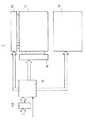
図1は、本実施形態の液晶表示装置1のブロック図である。 FIG. 1 is a block diagram of a liquid
液晶表示装置1は、コントローラ10、液晶パネル11、バックライト12、ソースドライバ回路14、ゲートドライバ回路16から構成されている。 The liquid
液晶パネル11は、OCB型の液晶を用いたものであり、20〜30インチの大きさを有している。この液晶パネル11は、アレイ基板と対向基板とから構成され、アレイ基板には信号線と走査線が互いに直交するように配線され、それらの交点にTFT(薄膜トランジスタ)が設けられ、また、アレイ基板と対向基板との間にOCBモードの液晶が挟持されている。 The
この液晶パネル11には、ソースドライバ回路14とゲートドライバ回路16が接続され、コントローラ10からの信号をソースドライバ回路14とゲートドライバ回路16が受けて、液晶パネル11に対し画像を表示する。 A
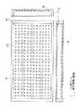
図2に示すように、バックライト12は、液晶パネル11の背面に配置され、このバックライト12は、点光源である白色LED18が、格子状に複数個配置されている。図2に示すように、液晶パネル11、バックライト12は各々複数の領域に分割されている。以下、この分割された領域を液晶パネル11では「表示領域」、バックライト12では「照明領域」という。そして、バックライト12は、縦に4個、横に8個の照明領域22を有しており、各照明領域22に縦に3個、横に3個の計9個のLED18が配置されている。 As shown in FIG. 2, the
コントローラ10は、RGBの画像信号をフレームメモリ20に記憶させ、その後受け取り、また、外部からのタイミング信号に基づいてソースドライバ回路14とゲートドライバ回路16及びバックライト12を制御する。このコントローラ10の制御については、後から詳しく説明する。 The
(2)画像処理の概要
コントローラ10の具体的な処理を説明する前に、本実施形態における画像処理の概要を説明する。(2) Overview of Image Processing Before describing specific processing of the
まず、コントローラ10は、背景技術で説明した黒挿入駆動法を行っている。すなわち、1フレーム毎に、かつ、1フレーム内において、画像信号の次の黒表示信号を挿入している。この表示を行うために、2倍速駆動を行っている。 First, the
ここで、本実施形態における黒挿入駆動法と、従来の黒挿入駆動法には異なる点がある。その異なる点とは、黒表示信号の階調にある。従来の黒表示信号の階調は、256階調の場合には0階調である。しかしながら、本実施形態における黒表示画像の階調は、1つの階調でなく或る幅を持ち、例えば0〜99階調の範囲を有している。このような100階調の黒表示信号を有する理由を次に説明する。 Here, there is a difference between the black insertion driving method in the present embodiment and the conventional black insertion driving method. The difference is in the gradation of the black display signal. The gradation of the conventional black display signal is 0 gradation in the case of 256 gradations. However, the gradation of the black display image in the present embodiment has a certain width instead of one gradation, for example, a range of 0 to 99 gradations. The reason for having such a black display signal of 100 gradations will be described next.
従来のOCB型の液晶表示装置においては、各照明領域でバックライト12の輝度を調整する場合には、画像信号の階調を補正している。すなわち、明るい場面の場合には、バックライトの輝度を最大に、かつ、画像信号の階調を最大(255階調)にしている。一方、最も暗い場面の場合にはバックライト12の輝度を最小(消灯)させ、かつ、画像信号の階調を最も暗く(0階調)にしている。これにより、より広くダイナミックレンジが取れる。 In the conventional OCB type liquid crystal display device, when adjusting the luminance of the
しかしながら、この方法では、背景技術で説明したように、タイミングを合わせるフレームメモリを用いない限り、図4(b)に示すようにバックライト12の輝度と画像信号の階調のタイミングとが一致せず、ちらつきが見えたりする場合がある。 However, in this method, as described in the background art, unless the frame memory for matching the timing is used, the luminance of the
そこで本出願人は、この問題点を解決するために、黒表示信号に着目した。この画像処理の方法について説明する。 Therefore, the present applicant paid attention to the black display signal in order to solve this problem. This image processing method will be described.
まず、RGBの画像信号については上記のような階調補正処理を行わず、ソースドライバ14に出力する。これにより、バックライト12の輝度とタイムラグが生じることがない。 First, the RGB image signal is output to the
そして、バックライト12の輝度と階調を合わせてダイナミックレンジを広くするために、黒表示信号の階調を調整する。すなわち、画像信号の表示の後に、黒表示信号を表示し、例えば、この時にバックライト12の輝度が上がった場合には黒表示信号の輝度(階調)を上げる。人間の目にはインパルス処理によって、階調を補正していない画像信号の次に階調が補正された明るい黒表示信号が表示されるため、あたかも画像信号に階調補正を行ったように見える。逆に、この時にバックライト12が消灯した場合には黒表示信号の輝度(階調)を下げる。人間の目にはインパルス処理によって、階調を補正していない画像信号の次に階調が補正された暗い黒表示信号が表示されるため、あたかも画像信号に階調補正を行ったように見える。 Then, the gradation of the black display signal is adjusted in order to increase the dynamic range by combining the luminance and gradation of the
そして、この黒表示信号の階調処理は、画像信号を表示している間に処理することができるため、図4(c)に示すように、黒表示信号とバックライト12の輝度との時間的な差がなく、ちらつきが生じたりすることがない。 Since the gradation processing of the black display signal can be performed while the image signal is displayed, the time between the black display signal and the luminance of the
(3)コントローラ10の具体的な処理方法
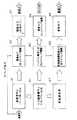
次に、図3に基づいて、コントローラ10の具体的な処理について説明する。図3は、コントローラ10内部の処理を示すブロック図である。(3) Specific Processing Method of
ブロックB1において、バッファ20に入力している画像信号を取り込む。 In block B1, the image signal input to the
ブロックB2において、外部から入力したタイミング信号に基づいて出力タイミングを調整し、ソースドライバ14に出力する。 In block B <b> 2, the output timing is adjusted based on the timing signal input from the outside and output to the
ブロックB3において、ソースドライバが、画像信号を出力する。 In block B3, the source driver outputs an image signal.
ブロックB4において、ブロックB1において取り込まれた画像信号に基づいて各表示領域におけるヒストグラムを生成する。すなわち、液晶パネル11を縦横複数の格子状の表示領域に分割し、各表示領域毎の輝度値の平均を取り、その平均した輝度値をその表示領域の代表値としてヒストグラムを生成する。 In block B4, a histogram in each display area is generated based on the image signal captured in block B1. That is, the
ブロックB5において、各表示領域のヒストグラム値である代表輝度値が生成されたため、その代表輝度値に基づいて各照明領域の輝度値を生成する。すなわち、この照明領域は、前記表示領域に対応する位置にあり、表示領域と照明領域とは必ずしも一致しないため、互いに対応する位置の代表輝度値を用いてバックライト12の輝度値を算出する。この対応しない例とは、後から説明する照明領域の境界部分である。このバックライト12の輝度値の算出方法は、表示領域の代表輝度値が高いほど、バックライト12の輝度値を上げ、逆に表示領域の代表輝度値が低いほどバックライト12の輝度値を下げる。 In block B5, since the representative luminance value which is the histogram value of each display area is generated, the luminance value of each illumination area is generated based on the representative luminance value. That is, the illumination area is at a position corresponding to the display area, and the display area and the illumination area do not necessarily match. Therefore, the luminance value of the
ブロックB6において、バックライト12の各照明領域に対応して白色LED18を点灯させ、バックライト12の各照明領域において異なる輝度値で点灯させる。 In block B <b> 6, the
ブロックB7において、ブロックB4において求めた表示領域毎のヒストグラム値(代表輝度値)に基づいて黒表示信号の階調を求める。上記で説明したように従来の黒表示信号の階調値は0階調のみであったが、本実施形態では、代表輝度値が高いほど明るい階調にし、代表輝度値が暗いほど暗い階調にする。この場合の規則としては、例えば256階調の場合、0〜99階調の範囲を黒表示信号の階調範囲とし、その中心にある50階調目を基準黒表示信号とする。そして、この基準黒表示信号を中心として代表輝度値が明るくなれば階調値を上げ、暗くなれば暗くなるように変換する。 In block B7, the gradation of the black display signal is obtained based on the histogram value (representative luminance value) for each display area obtained in block B4. As described above, the gradation value of the conventional black display signal is only 0 gradation, but in this embodiment, the higher the representative luminance value, the brighter the gradation, and the darker the representative luminance value, the darker the gradation. To. As a rule in this case, for example, in the case of 256 gradations, the range of 0 to 99 gradations is set as the gradation range of the black display signal, and the 50th gradation at the center is set as the reference black display signal. Then, with the reference black display signal as a center, the gradation value is increased when the representative luminance value becomes brighter, and is converted to become darker when it becomes darker.
ブロックB8において、ブロックB2において出力された画像信号の次にこの変換された黒表示信号を出力できるようにタイミングを調整する。 In block B8, the timing is adjusted so that the converted black display signal can be output next to the image signal output in block B2.
ブロックB9において、1フレーム毎に、かつ、1フレーム内にあって画像信号の次に黒表示信号を出力する。 In block B9, a black display signal is output after every image frame and within one frame after the image signal.
上記のような画像表示の制御を行うことにより、階調が制御された黒表示信号を画像信号の次に出力することができる。 By controlling the image display as described above, a black display signal whose gradation is controlled can be output next to the image signal.
(4)境界部分の処理
上記のような画像表示の制御を行ったときに、照明領域の境界部分においてバックライト12の輝度値に差がある場合にはその部分が筋として見える場合がある。(4) Processing of boundary portion When the image display control as described above is performed, if there is a difference in the luminance value of the
そこで、本実施形態ではブロックB5において求めた各照明領域の輝度値に差がある場合、すなわち所定値以上の差がある場合には、照明領域の境界部分において、図5に示すようにその変化が傾斜するようにブロックB8において黒表示信号の階調を調整する。 Therefore, in the present embodiment, when there is a difference in the luminance value of each illumination area obtained in block B5, that is, when there is a difference greater than or equal to a predetermined value, the change in the boundary part of the illumination area as shown in FIG. The gradation of the black display signal is adjusted in block B8 so that is inclined.
このようにすることで、図5(b)に示すように、調整後の輝度が照明領域間においても滑らかになるため、ちらつきとして認識されることがない。 By doing in this way, as shown in FIG.5 (b), since the brightness | luminance after adjustment becomes smooth also between illumination areas, it is not recognized as a flicker.
(5)変更例
本発明は上記各実施形態に限らず、その主旨を逸脱しない限り種々に変更することができる。(5) Modification Examples The present invention is not limited to the above-described embodiments, and various modifications can be made without departing from the gist thereof.
上記実施形態ではOCB液晶の場合について説明したが、これ以外のTN型液晶等においても本発明を適用することができる。 In the above embodiment, the OCB liquid crystal has been described. However, the present invention can be applied to other TN liquid crystal.
OCB液晶においては黒表示信号を階調補正信号として用いたが、それ以外の液晶においては、2倍速駆動で画像信号を処理した後、階調補正信号を挿入して上記と同様の処理を行う。この場合、OCB液晶の黒表示信号では0〜99階調に限られていたが、単に階調補正信号として挿入する場合には0〜255階調の全ての範囲で階調補正信号を表示することができる。 In the OCB liquid crystal, the black display signal is used as the gradation correction signal. In other liquid crystals, the image signal is processed by the double speed drive, and then the gradation correction signal is inserted to perform the same processing as described above. . In this case, the black display signal of the OCB liquid crystal is limited to 0 to 99 gradations, but when it is simply inserted as a gradation correction signal, the gradation correction signal is displayed in the entire range of 0 to 255 gradations. be able to.
1 液晶表示装置
10 コントローラ
11 液晶パネル
12 バックライト
14 ソースドライバ回路
16 ゲートドライバ回路
18 白色LED
20 バッファDESCRIPTION OF
20 buffers
Claims (3)
Translated fromJapanese照明領域を縦横方向にそれぞれ複数有し、前記各照明領域にそれぞれ対応する前記液晶パネルの各表示領域をそれぞれ照明するバックライトと、
前記各照明領域のそれぞれの輝度を前記画像信号に基づいて算出するバックライト制御部と、
1フレーム毎であって、かつ、前記1フレーム内において、前記画像信号の次に階調補正信号を挿入するものであって、一つの前記照明領域に対応する前記表示領域に含まれる前記画像信号の輝度が高い程に前記階調補正信号の輝度を上げる階調補正部と、
前記1フレーム毎であって、かつ、前記1フレーム内において、前記画像信号に基づいて画像を表示し、次に前記階調補正信号に基づいて階調補正画像を表示する表示制御部と、
を有する液晶表示装置。A liquid crystal panel for displaying an image based on an image signal;
A plurality of illumination areas in the vertical and horizontal directions, and a backlight for illuminating each display area of the liquid crystal panel corresponding to each of the illumination areas;
A backlight control unit that calculates the brightness of each illumination area based on the image signal;
The image signal included in the display area corresponding to one illumination area, which is for each frame and in which the gradation correction signal is inserted after the image signal in the one frame. A tone correction unit that increases the brightness of the tone correction signal as the brightness of
A display control unit that displays the image based on the image signal and then displays the gradation correction image based on the gradation correction signal every frame and within the one frame;
A liquid crystal display device.
隣接する前記照明領域における前記階調補正信号の輝度の差がある場合には、隣接する前記照明領域の境界部分の前記階調補正信号の輝度変化を傾斜させて滑らかにする、
請求項1記載の液晶表示装置。The gradation correction unit
When there is a difference in brightness of the gradation correction signal in the adjacent illumination area, the brightness change of the gradation correction signal at the boundary portion of the adjacent illumination area is inclined and smoothed.
The liquid crystal display device according to claim 1.
前記階調補正信号は、黒表示信号である、
請求項1記載の液晶表示装置。The liquid crystal panel is an OCB mode liquid crystal panel,
The gradation correction signal is a black display signal.
The liquid crystal display device according to claim 1.
Priority Applications (1)
| Application Number | Priority Date | Filing Date | Title |
|---|---|---|---|
| JP2008013699AJP2009175414A (en) | 2008-01-24 | 2008-01-24 | Liquid crystal display device |
Applications Claiming Priority (1)
| Application Number | Priority Date | Filing Date | Title |
|---|---|---|---|
| JP2008013699AJP2009175414A (en) | 2008-01-24 | 2008-01-24 | Liquid crystal display device |
Publications (1)
| Publication Number | Publication Date |
|---|---|
| JP2009175414Atrue JP2009175414A (en) | 2009-08-06 |
Family
ID=41030579
Family Applications (1)
| Application Number | Title | Priority Date | Filing Date |
|---|---|---|---|
| JP2008013699APendingJP2009175414A (en) | 2008-01-24 | 2008-01-24 | Liquid crystal display device |
Country Status (1)
| Country | Link |
|---|---|
| JP (1) | JP2009175414A (en) |
Cited By (1)
| Publication number | Priority date | Publication date | Assignee | Title |
|---|---|---|---|---|
| JP2013246261A (en)* | 2012-05-24 | 2013-12-09 | Sharp Corp | Display device and method of driving display device |
Citations (5)
| Publication number | Priority date | Publication date | Assignee | Title |
|---|---|---|---|---|
| JP2005258403A (en)* | 2004-02-09 | 2005-09-22 | Hitachi Ltd | LIGHTING DEVICE, IMAGE DISPLAY DEVICE HAVING THE SAME, AND IMAGE DISPLAY METHOD |
| JP2007155840A (en)* | 2005-11-30 | 2007-06-21 | Nec Lcd Technologies Ltd | Image display device, drive circuit used in image display device, and drive method |
| JP2007240858A (en)* | 2006-03-08 | 2007-09-20 | Mitsubishi Electric Corp | LIGHTING DEVICE, VIDEO DISPLAY DEVICE, AND VIDEO SIGNAL CONTROL METHOD |
| JP2007286610A (en)* | 2006-03-22 | 2007-11-01 | Fujifilm Corp | Liquid crystal display device and display method |
| JP2007304561A (en)* | 2006-03-23 | 2007-11-22 | Toshiba Matsushita Display Technology Co Ltd | Driving device of liquid crystal display device |
- 2008
- 2008-01-24JPJP2008013699Apatent/JP2009175414A/enactivePending
Patent Citations (5)
| Publication number | Priority date | Publication date | Assignee | Title |
|---|---|---|---|---|
| JP2005258403A (en)* | 2004-02-09 | 2005-09-22 | Hitachi Ltd | LIGHTING DEVICE, IMAGE DISPLAY DEVICE HAVING THE SAME, AND IMAGE DISPLAY METHOD |
| JP2007155840A (en)* | 2005-11-30 | 2007-06-21 | Nec Lcd Technologies Ltd | Image display device, drive circuit used in image display device, and drive method |
| JP2007240858A (en)* | 2006-03-08 | 2007-09-20 | Mitsubishi Electric Corp | LIGHTING DEVICE, VIDEO DISPLAY DEVICE, AND VIDEO SIGNAL CONTROL METHOD |
| JP2007286610A (en)* | 2006-03-22 | 2007-11-01 | Fujifilm Corp | Liquid crystal display device and display method |
| JP2007304561A (en)* | 2006-03-23 | 2007-11-22 | Toshiba Matsushita Display Technology Co Ltd | Driving device of liquid crystal display device |
Cited By (1)
| Publication number | Priority date | Publication date | Assignee | Title |
|---|---|---|---|---|
| JP2013246261A (en)* | 2012-05-24 | 2013-12-09 | Sharp Corp | Display device and method of driving display device |
Similar Documents
| Publication | Publication Date | Title |
|---|---|---|
| JP6898971B2 (en) | Display device drive | |
| JP5036694B2 (en) | Backlight driving circuit and driving method thereof | |
| JP5220268B2 (en) | Display device | |
| JP4405481B2 (en) | Liquid crystal display | |
| US8797370B2 (en) | Liquid crystal display and local dimming control method thereof | |
| CN102483907B (en) | Display device | |
| WO2014162794A1 (en) | Liquid crystal display device and driving method therefor | |
| JP5281233B2 (en) | Display device and driving method of display device | |
| US9183797B2 (en) | Display device and control method for display device | |
| US9990878B2 (en) | Data clipping method using red, green, blue and white data, and display device using the same | |
| JPWO2009054223A1 (en) | Image display device | |
| JP2010152174A (en) | Image processing apparatus and image display device | |
| WO2011025004A1 (en) | Liquid crystal display device and television receiver | |
| JP6085395B2 (en) | Liquid crystal display device and display method | |
| JP2013083978A (en) | Display device and driving method for the same | |
| US11651746B2 (en) | Backlight driving device and operating method thereof | |
| JP5286520B2 (en) | Liquid crystal display | |
| TWI545540B (en) | Displaying apparatus with titled screen and display driving method thereof | |
| TWI410943B (en) | Liquid crystal display for reducing motion blur | |
| CN100552753C (en) | Display device | |
| JP2009031755A (en) | Liquid crystal display device | |
| KR20200042564A (en) | Display apparatus and method of driving the same | |
| JP2009175415A (en) | Liquid crystal display device | |
| JP5197153B2 (en) | Liquid crystal display | |
| JP2008176111A (en) | Image display device and image display method |
Legal Events
| Date | Code | Title | Description |
|---|---|---|---|
| A621 | Written request for application examination | Free format text:JAPANESE INTERMEDIATE CODE: A621 Effective date:20101228 | |
| A977 | Report on retrieval | Free format text:JAPANESE INTERMEDIATE CODE: A971007 Effective date:20121228 | |
| A131 | Notification of reasons for refusal | Free format text:JAPANESE INTERMEDIATE CODE: A131 Effective date:20130122 | |
| A521 | Written amendment | Free format text:JAPANESE INTERMEDIATE CODE: A523 Effective date:20130319 | |
| A131 | Notification of reasons for refusal | Free format text:JAPANESE INTERMEDIATE CODE: A131 Effective date:20131224 | |
| A521 | Written amendment | Free format text:JAPANESE INTERMEDIATE CODE: A523 Effective date:20140220 | |
| A711 | Notification of change in applicant | Free format text:JAPANESE INTERMEDIATE CODE: A712 Effective date:20140228 | |
| A02 | Decision of refusal | Free format text:JAPANESE INTERMEDIATE CODE: A02 Effective date:20140930 |