Movatterモバイル変換


[0]ホーム

URL:


JP2009172732A - Impact rotary tool - Google Patents

Impact rotary tool
Download PDF

Info

Publication number
JP2009172732A
JP2009172732AJP2008015423AJP2008015423AJP2009172732AJP 2009172732 AJP2009172732 AJP 2009172732AJP 2008015423 AJP2008015423 AJP 2008015423AJP 2008015423 AJP2008015423 AJP 2008015423AJP 2009172732 AJP2009172732 AJP 2009172732A
Authority
JP
Japan
Prior art keywords
hammer
anvil
drive shaft
elastic body
rotary tool
Prior art date
Legal status (The legal status is an assumption and is not a legal conclusion. Google has not performed a legal analysis and makes no representation as to the accuracy of the status listed.)
Withdrawn
Application number
JP2008015423A
Other languages
Japanese (ja)
Inventor
Masatoshi Atsumi
将利 渥美
Hideki Shimizu
秀規 清水
Fumiaki Sawano
史明 沢野
Atsushi Takeyama
敦 竹山
Current Assignee (The listed assignees may be inaccurate. Google has not performed a legal analysis and makes no representation or warranty as to the accuracy of the list.)
Panasonic Electric Works Co Ltd
Original Assignee
Panasonic Electric Works Co Ltd
Priority date (The priority date is an assumption and is not a legal conclusion. Google has not performed a legal analysis and makes no representation as to the accuracy of the date listed.)
Filing date
Publication date
Application filed by Panasonic Electric Works Co LtdfiledCriticalPanasonic Electric Works Co Ltd
Priority to JP2008015423ApriorityCriticalpatent/JP2009172732A/en
Publication of JP2009172732ApublicationCriticalpatent/JP2009172732A/en
Withdrawnlegal-statusCriticalCurrent

Links

Images

Landscapes

Abstract

Translated fromJapanese

【課題】インパクト回転工具において、弾性体の破断を防止して、カム機構内における振動及び騒音の発生を確実に防止する。
【解決手段】インパクト回転工具1は、モータ2を動力とする駆動軸12と、駆動軸12の回転が出力されるアンビル13と、アンビル13を打撃するハンマ14と、ハンマ14にアンビル13を打撃する動作を行わせるカム機構15と、ハンマ14をアンビル13側に向けて付勢するハンマバネ16とを備える。ハンマバネ16の後端側にあるプレート38の前方には、鋼球36、36が駆動軸12の軸部カム溝34、34の後端壁に衝突して騒音及び振動が発生することがないように、ハンマ14の後退量を制限する金属板40が弾性体41を介して設けられる。ハンマバネ16は、弾性体41の外径の変形量を規制するように設定されており、弾性体41が上述の衝撃力を吸収して過剰に圧縮されることを防止する規制部材として機能する。
【選択図】図3
In an impact rotary tool, an elastic body is prevented from being broken and vibration and noise are reliably prevented from occurring in a cam mechanism.
An impact rotary tool 1 includes a drive shaft 12 powered by a motor 2, an anvil 13 that outputs rotation of the drive shaft 12, a hammer 14 that strikes the anvil 13, and a hammer 14 that strikes the anvil 13 And a hammer spring 16 that biases the hammer 14 toward the anvil 13 side. In front of the plate 38 on the rear end side of the hammer spring 16, the steel balls 36, 36 do not collide with the rear end walls of the shaft cam grooves 34, 34 of the drive shaft 12 to generate noise and vibration. In addition, a metal plate 40 that restricts the retraction amount of the hammer 14 is provided via an elastic body 41. The hammer spring 16 is set so as to restrict the amount of deformation of the outer diameter of the elastic body 41, and functions as a restricting member that prevents the elastic body 41 from being excessively compressed by absorbing the above-described impact force.
[Selection] Figure 3

Description

Translated fromJapanese

本発明は、ボルトやナット等のねじの締め付け作業に使用されるインパクトレンチやインパクトドライバ等のインパクト回転工具に関するものである。  The present invention relates to an impact rotary tool such as an impact wrench or an impact driver used for tightening screws such as bolts and nuts.

インパクト回転工具は、回転駆動される駆動軸と連結されたハンマが、出力軸に設けられたアンビルを打撃することにより、打撃による強い衝撃力が出力軸に付加され、出力軸が回転するものである。駆動軸とハンマは、カム機構を介して互いに相対回転可能に且つ前進後退可能に連結されており、駆動軸とハンマの間には、ハンマをアンビル側に向けて付勢するハンマバネが設けられている。  The impact rotary tool is a tool in which a hammer connected to a rotationally driven drive shaft strikes an anvil provided on the output shaft, so that a strong impact force is applied to the output shaft and the output shaft rotates. is there. The drive shaft and the hammer are connected to each other via a cam mechanism so as to be relatively rotatable and capable of moving forward and backward. A hammer spring is provided between the drive shaft and the hammer to urge the hammer toward the anvil. Yes.

ところで、ハンマはハンマバネに蓄積されたバネ力により前進し、一方、出力軸がボルト等の対象部材からの反力を受け、出力軸の回転が減速してハンマの回転が駆動軸に対して遅れるときにカム機構により、ハンマは後退するようになっている。このような工具において、ハンマが後退したとき、カム機構に設けられた鋼球がカム溝の端部壁に衝突して、騒音及び振動が発生することがある。そこで、このような騒音や振動の発生を防止するものとして、ハンマの後退量を制限する弾性体をハンマの後方に設けたインパクト回転工具が知られている(例えば、特許文献1及び特許文献2参照)。
特開2002−46078号公報特開平11−320432号公報
By the way, the hammer moves forward by the spring force accumulated in the hammer spring, while the output shaft receives a reaction force from a target member such as a bolt, and the rotation of the output shaft is decelerated and the rotation of the hammer is delayed with respect to the drive shaft. Sometimes, the cam mechanism causes the hammer to retreat. In such a tool, when the hammer is retracted, a steel ball provided in the cam mechanism may collide with the end wall of the cam groove to generate noise and vibration. In order to prevent such noise and vibration from occurring, an impact rotary tool in which an elastic body that restricts the amount of retraction of the hammer is provided behind the hammer is known (for example, Patent Document 1 and Patent Document 2). reference).
JP 2002-46078 A JP-A-11-320432

しかしながら、上述のような従来の工具では、対象部材の剛性が大きい場合やねじのかじりが発生した場合、ハンマに大きな反力が作用することになり、ハンマが勢いよく後退することで弾性体に大きな衝撃力が作用する。そのため、弾性体の破断を引き起こすことがあり、上述の振動と騒音を確実に防止することができない。  However, in the conventional tool as described above, when the rigidity of the target member is large or when screw galling occurs, a large reaction force acts on the hammer, and the hammer retreats vigorously to the elastic body. A large impact force is applied. Therefore, the elastic body may be broken, and the above vibration and noise cannot be reliably prevented.

本発明は、上記問題を解決するためになされたものであり、弾性体の破断を防止して、カム機構内における振動及び騒音の発生を確実に防止することが可能なインパクト回転工具を提供することを目的とする。  The present invention has been made to solve the above problem, and provides an impact rotary tool capable of preventing the occurrence of vibration and noise in the cam mechanism by preventing the elastic body from breaking. For the purpose.

上記目的を達成するために請求項1の発明は、モータを動力とする駆動軸と、前記駆動軸の回転が出力されるアンビルと、前記アンビルを打撃するハンマと、前記ハンマに前記アンビルを打撃する動作を行わせるカム機構と、前記ハンマが後退することにより圧縮され、当該ハンマをアンビル側に向けて付勢するハンマバネとを備えたインパクト回転工具において、前記ハンマの前記駆動軸に対する相対回転の遅れに伴って、当該ハンマが前記カム機構により当該駆動軸に対して後退するときに生じる衝撃力を緩和する弾性体と、前記弾性体の外径の変形量を規制する規制部材とをさらに備えるものである。  In order to achieve the above object, a first aspect of the present invention is directed to a drive shaft driven by a motor, an anvil that outputs rotation of the drive shaft, a hammer that strikes the anvil, and a hammer that strikes the anvil. In an impact rotary tool comprising a cam mechanism for performing an operation to be performed and a hammer spring that is compressed by retreating the hammer and biases the hammer toward the anvil, the hammer rotates relative to the drive shaft. An elastic body that alleviates an impact force that occurs when the hammer moves backward with respect to the drive shaft by the cam mechanism with a delay, and a regulating member that regulates the deformation amount of the outer diameter of the elastic body. Is.

請求項2の発明は、請求項1に記載の発明において、前記規制部材は、前記ハンマバネの一部分となるように構成されたものである。  According to a second aspect of the present invention, in the first aspect of the present invention, the restricting member is configured to be a part of the hammer spring.

請求項3の発明は、請求項1に記載の発明において、前記規制部材は、リング状に形成されているものである。  According to a third aspect of the present invention, in the first aspect of the present invention, the regulating member is formed in a ring shape.

請求項1の発明によれば、ハンマが後退するときに生じる衝撃力により弾性体が径方向に増大することが抑制されるので、弾性体が過剰に圧縮されることがなくなり、弾性体の破損を防止することができる。そのため、カム機構内における振動及び騒音の発生を確実に防止でき、ユーザは本工具を快適に使用することが可能となる。  According to the invention of claim 1, since the elastic body is restrained from increasing in the radial direction due to the impact force generated when the hammer is retracted, the elastic body is not excessively compressed, and the elastic body is damaged. Can be prevented. Therefore, the generation of vibration and noise in the cam mechanism can be reliably prevented, and the user can comfortably use the tool.

請求項2の発明によれば、規制部材がハンマバネの一部分となるように構成されているので、弾性体が径方向に増大して規制部材と当接するとき、当該弾性体には圧縮されたハンマバネから均一な力が加わり、傷や偏応力による弾性体の耐久性の低下を防止することができる。  According to the invention ofclaim 2, since the restricting member is configured to become a part of the hammer spring, when the elastic body increases in the radial direction and comes into contact with the restricting member, the elastic spring is compressed into the elastic spring. Therefore, a uniform force can be applied to prevent a decrease in durability of the elastic body due to scratches or partial stress.

請求項2の発明と同様に、弾性体の耐久性の低下を防止することができるインパクト回転工具が得られる。  Similarly to the invention ofclaim 2, an impact rotary tool capable of preventing a decrease in durability of the elastic body is obtained.

(第1の実施形態)
本発明の第1の実施形態に係るインパクト回転工具について図1乃至図3を参照して説明する。図1は本実施形態に係るインパクト回転工具1の概略構成を示す。インパクト回転工具(以下、本工具という)1は、駆動源であるモータ2と、モータ2と接続され、先端に取り付けられるビット3を打撃力を付加して回転させる打撃機構部4と、モータ2を制御する制御回路5と、上記各部を収容する本体カバー6と、本体カバー6に着脱自在に取り付けられる充電池7を備える。ここで、ビット3は、ボルトやナット等のねじの種類に応じて多数の種類があり、打撃機構部4に着脱自在に取り付けられる。
(First embodiment)
An impact rotary tool according to a first embodiment of the present invention will be described with reference to FIGS. 1 to 3. FIG. 1 shows a schematic configuration of an impact rotary tool 1 according to the present embodiment. An impact rotating tool (hereinafter referred to as this tool) 1 includes amotor 2 that is a driving source, astriking mechanism unit 4 that is connected to themotor 2 and rotates abit 3 attached to the tip with a striking force, and amotor 2. And arechargeable battery 7 that is detachably attached to themain body cover 6. Here, thebit 3 has many types according to the types of screws such as bolts and nuts, and is detachably attached to thestriking mechanism unit 4.

制御回路5は、ユーザが後述するトリガスイッチ8を引き込むことで、充電池7から電力をモータ2に供給し、トリガスイッチ8の引き込み量に応じた回転速度でモータ2を回転させる。本体カバー6は、モータ2及び打撃機構部4を収容するハウジング部9と、制御回路5を収容する共に操作に際しユーザによって把持されるように形成されたグリップ部10で構成される。グリップ部10の前面には、モータ2の起動とその回転速度の調整を行うためのトリガスイッチ8が設けられている。  Thecontrol circuit 5 supplies power from therechargeable battery 7 to themotor 2 when the user pulls in a trigger switch 8 to be described later, and rotates themotor 2 at a rotation speed corresponding to the pull-in amount of the trigger switch 8. Themain body cover 6 includes ahousing portion 9 that accommodates themotor 2 and thestriking mechanism portion 4 and agrip portion 10 that accommodates thecontrol circuit 5 and is formed so as to be gripped by the user during operation. A trigger switch 8 for starting themotor 2 and adjusting its rotational speed is provided on the front surface of thegrip portion 10.

図2は打撃機構部4の内部構成を示す。打撃機構部4は、モータ2と減速機11を介して接続される駆動軸12と、駆動軸12の回転が出力されるアンビル13と、アンビル13を打撃するハンマ14と、ハンマ14にアンビル13を打撃する動作を行わせるカム機構15と、ハンマ14をアンビル13側に向けて付勢するハンマバネ16とを備える。  FIG. 2 shows an internal configuration of thestriking mechanism unit 4. Thestriking mechanism unit 4 includes adrive shaft 12 connected via themotor 2 and thespeed reducer 11, ananvil 13 that outputs rotation of thedrive shaft 12, ahammer 14 that strikes theanvil 13, and ananvil 13 on thehammer 14. And ahammer spring 16 that urges thehammer 14 toward theanvil 13 side.

減速機11は、モータ2の前方に配置される。減速機11は、遊星歯車機構であって、モータ2の回転軸17に形成されたギアである太陽ギア18と、太陽ギア18と噛み合う複数の遊星ギア19、19と、遊星ギア19、19と噛み合うリングギア20と、上記各部を収容するケース21とで構成される。太陽ギア18は、駆動軸12の中央に形成された孔22に差し込まれている。遊星ギア19、19は、太陽ギア18の周囲に配置され、駆動軸12の後端側に形成されるキャリア23に挿通された軸24、24によってそれぞれの中心が固定されている。リングギア20はケース21の内周壁に固定されており、ケース21は本体カバー6のハウジング部9に固定されている。上記のように減速機11を構成することで、モータ2の回転が上記各ギアにより定められる所定の減速比で減速され、駆動軸12に伝達される。  Thespeed reducer 11 is disposed in front of themotor 2. Thespeed reducer 11 is a planetary gear mechanism, and includes a sun gear 18 that is a gear formed on the rotatingshaft 17 of themotor 2, a plurality ofplanetary gears 19 and 19 that mesh with the sun gear 18, andplanetary gears 19 and 19. It comprises aring gear 20 that meshes with each other and acase 21 that accommodates each of the above parts. The sun gear 18 is inserted into a hole 22 formed in the center of thedrive shaft 12. Theplanetary gears 19, 19 are arranged around the sun gear 18, and their centers are fixed byshafts 24, 24 inserted through acarrier 23 formed on the rear end side of thedrive shaft 12. Thering gear 20 is fixed to the inner peripheral wall of thecase 21, and thecase 21 is fixed to thehousing portion 9 of themain body cover 6. By configuring thereduction gear 11 as described above, the rotation of themotor 2 is decelerated at a predetermined reduction ratio determined by each gear and transmitted to thedrive shaft 12.

駆動軸12は、上述したキャリア23と、キャリア23の中心を通る軸部25で構成される。軸部25は、後端側が減速機11のケース21内に固定されたベアリング26により保持され、前端側がアンビル13に形成された後部穴27により回転自在に保持されている。  Thedrive shaft 12 includes thecarrier 23 described above and ashaft portion 25 that passes through the center of thecarrier 23. Theshaft portion 25 is held at the rear end side by a bearing 26 fixed in thecase 21 of thespeed reducer 11, and the front end side is rotatably held by arear hole 27 formed in theanvil 13.

アンビル13は、ハンマ14の前方に配置されており、後端側にはハンマ14によって打撃される際にハンマ14と係合するアーム部28、28が形成されている。アンビル13は、本体カバー6のハウジング部9の前端側に固定されたメタル軸受29により保持されており、前端側がハウジング部9の前端面より突出している。アンビル13の前端側には、ビット3を挿入するためのビット挿入穴30が形成されていると共に、ビット挿入穴30に挿入したビット3を固定するためのチャック機構31が設けられている。  Theanvil 13 is disposed in front of thehammer 14, andarm portions 28, 28 that engage with thehammer 14 when being hit by thehammer 14 are formed on the rear end side. Theanvil 13 is held by a metal bearing 29 fixed to the front end side of thehousing part 9 of themain body cover 6, and the front end side protrudes from the front end surface of thehousing part 9. Abit insertion hole 30 for inserting thebit 3 is formed on the front end side of theanvil 13, and achuck mechanism 31 for fixing thebit 3 inserted into thebit insertion hole 30 is provided.

ハンマ14は、その中央に駆動軸12の軸部25が遊嵌される貫通孔32を有しており、駆動軸12に対して相対回転可能に且つ前進後退可能に連結されている。ハンマ14は、ハンマバネ16の復元力により、アンビル13側に向けて付勢されている。ハンマ14の前端側には、アンビル13のアーム部28、28と係合するハンマ爪33、33が放射状に形成されている。  Thehammer 14 has a throughhole 32 in which theshaft portion 25 of thedrive shaft 12 is loosely fitted at the center thereof, and is connected to thedrive shaft 12 so as to be relatively rotatable and capable of moving forward and backward. Thehammer 14 is biased toward theanvil 13 side by the restoring force of thehammer spring 16. On the front end side of thehammer 14,hammer claws 33, 33 that engage with thearm portions 28, 28 of theanvil 13 are formed radially.

カム機構15は、軸部25の前側外周面に螺旋状に形成された軸部カム溝34、34と、ハンマ14の内周面に形成されたハンマカム溝35、35と、軸部カム溝34、34とハンマカム溝35、35の双方に係合する鋼球36、36とで構成される。軸部カム溝34、34とハンマカム溝35、35はそれぞれ、鋼球36、36の半球分が入り込めるように形成されており、軸部カム溝34、34とハンマカム溝35、35が重なって形成される空間に鋼球36、36が配設されている。上記のようなカム機構15を構成することで、駆動軸12の回転が鋼球36、36を介してハンマ14に伝達される。  Thecam mechanism 15 includesshaft cam grooves 34 and 34 formed in a spiral shape on the front outer peripheral surface of theshaft portion 25,hammer cam grooves 35 and 35 formed on the inner peripheral surface of thehammer 14, and ashaft cam groove 34. , 34 and thesteel balls 36, 36 engaged with both thehammer cam grooves 35, 35. Theshaft cam grooves 34 and 34 and thehammer cam grooves 35 and 35 are formed so that hemispheres of thesteel balls 36 and 36 can enter, respectively, and theshaft cam grooves 34 and 34 and thehammer cam grooves 35 and 35 are overlapped.Steel balls 36, 36 are disposed in the space to be formed. By configuring thecam mechanism 15 as described above, the rotation of thedrive shaft 12 is transmitted to thehammer 14 via thesteel balls 36 and 36.

ハンマバネ16は、中央の空間37に駆動軸12の軸部25が挿通され、駆動軸12のキャリア23部とハンマ14の間に圧縮されて配設されている。ハンマバネ16は、後端側がキャリア23部に固定されたプレート38により保持され、前端側がハンマ14に固定されたプレート39により保持されている。  Thehammer spring 16 is inserted in thecentral space 37 through theshaft portion 25 of thedrive shaft 12 and is compressed between thecarrier 23 portion of thedrive shaft 12 and thehammer 14. Thehammer spring 16 is held by aplate 38 whose rear end side is fixed to thecarrier 23, and is held by aplate 39 whose front end side is fixed to thehammer 14.

ハンマバネ16の後端側にある上記プレート38の前方には、ハンマ14が駆動軸12に対して後退するときに、鋼球36、36が駆動軸12の軸部カム溝34、34の後端壁(図示しない)に衝突して騒音及び振動が発生することがないように、ハンマ14の後退量を制限する金属板40が弾性体41を介して設けられる。弾性体41は、金属板40とハンマ14が当接するときに生じる衝撃力を緩和するためのものである。金属板40と弾性体41は、軸部25が挿通されると共にハンマバネ16の空間37に位置するようにリング状に形成されている。ここで、上述したハンマバネ16は、その内径が弾性体41の外径の変形量を規制するように設定されており、弾性体41が上述の衝撃力を吸収して過剰に圧縮されることを防止する規制部材として機能する。  In front of theplate 38 on the rear end side of thehammer spring 16, when thehammer 14 is retracted with respect to thedrive shaft 12, thesteel balls 36, 36 are rear end portions of theshaft cam grooves 34, 34 of thedrive shaft 12. Ametal plate 40 for limiting the amount of retraction of thehammer 14 is provided via anelastic body 41 so that noise and vibration are not generated by colliding with a wall (not shown). Theelastic body 41 is for alleviating the impact force generated when themetal plate 40 and thehammer 14 come into contact with each other. Themetal plate 40 and theelastic body 41 are formed in a ring shape so that theshaft portion 25 is inserted and positioned in thespace 37 of thehammer spring 16. Here, the above-describedhammer spring 16 is set so that the inner diameter thereof regulates the deformation amount of the outer diameter of theelastic body 41, and theelastic body 41 absorbs the above-described impact force and is compressed excessively. It functions as a regulating member to prevent.

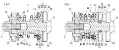
次に、上記のように構成されたインパクト回転工具1における打撃機構部4の動作について説明する。図3(a)(b)は上記打撃機構部4の動作状態を示しており、(a)はハンマ14が最大限前進した状態を示し、(b)はハンマ14が最大限後退した状態を示す。  Next, operation | movement of thestriking mechanism part 4 in the impact rotary tool 1 comprised as mentioned above is demonstrated. 3 (a) and 3 (b) show the operating state of thestriking mechanism 4, wherein (a) shows the state where thehammer 14 has advanced to the maximum, and (b) shows the state where thehammer 14 has retracted to the maximum. Show.

ねじの締付を開始する前は、図3(a)のように、ハンマ14がハンマバネ16の復元力によりアンビル13側に向けて付勢され、ハンマ14のハンマ爪33、33とアンビル13のアーム部28、28が係合している。ユーザがトリガスイッチ8を引き込んでねじの締付を開始すると、モータ2が回転する。モータ2の回転は減速機11にて減速されて駆動軸12に出力され、駆動軸12の回転は鋼球36、36を介してハンマ14に伝達される。このとき、ハンマ爪33、33とアーム部28、28が係合しているので、ハンマ14の回転はアンビル13に伝達され、アンビル13に取り付けられたビット3が回転する。  Before starting the tightening of the screw, as shown in FIG. 3A, thehammer 14 is urged toward theanvil 13 side by the restoring force of thehammer spring 16, and thehammer claws 33 and 33 of thehammer 14 and theanvil 13 Thearm portions 28 are engaged. When the user pulls in the trigger switch 8 and starts tightening the screw, themotor 2 rotates. The rotation of themotor 2 is decelerated by thespeed reducer 11 and output to thedrive shaft 12, and the rotation of thedrive shaft 12 is transmitted to thehammer 14 via thesteel balls 36 and 36. At this time, since thehammer claws 33, 33 and thearm portions 28, 28 are engaged, the rotation of thehammer 14 is transmitted to theanvil 13, and thebit 3 attached to theanvil 13 rotates.

ここで、ねじの締付トルクが高くなって、アンビル13に大きな負荷がかかった場合について述べる。この場合、アンビル13の回転が遅くなり、これに伴って、ハンマ14の回転が遅くなって駆動軸12の回転に対して相対的に遅れることになる。すると、鋼球36、36が軸部カム溝34、34の前端壁から後退し、これに伴ってハンマ14がハンマバネ16を圧縮しながら駆動軸12に対して後退し、ハンマ爪33、33とアーム部28、28の係合が外れる。その後、ハンマ14は、図3(b)のように、金属板40及び弾性体41により制限される位置まで後退する。このとき、鋼球36、36が駆動軸12の軸部カム溝34、34の後端壁に衝突することはない。ここで、ハンマ14が金属板40と当接したとき、弾性体41は軸方向に圧縮されて径方向に増大し、その外周面と圧縮されたハンマバネ16の内側が当接する。  Here, a case where the tightening torque of the screw is increased and a large load is applied to theanvil 13 will be described. In this case, the rotation of theanvil 13 is delayed, and accordingly, the rotation of thehammer 14 is delayed and is relatively delayed with respect to the rotation of thedrive shaft 12. Then, thesteel balls 36 and 36 are retracted from the front end walls of theshaft cam grooves 34 and 34, and thehammer 14 is retracted with respect to thedrive shaft 12 while compressing thehammer spring 16. Thearms 28, 28 are disengaged. Thereafter, thehammer 14 retreats to a position limited by themetal plate 40 and theelastic body 41 as shown in FIG. At this time, thesteel balls 36 and 36 do not collide with the rear end walls of theshaft cam grooves 34 and 34 of thedrive shaft 12. Here, when thehammer 14 comes into contact with themetal plate 40, theelastic body 41 is compressed in the axial direction and increases in the radial direction, and the outer peripheral surface thereof comes into contact with the inside of thecompressed hammer spring 16.

その後、鋼球36、36はハンマバネ16の復元力により軸部カム溝34、34に沿って前進し、これに伴ってハンマ14が駆動軸12に対して前進する。すると、ハンマ14のハンマ爪33、33とアンビル13のアーム部28、28が再び係合し、アンビル13がハンマ14によって打撃されてアンビル13に回転力が加えられる。  Thereafter, thesteel balls 36 and 36 are moved forward along theshaft cam grooves 34 and 34 by the restoring force of thehammer spring 16, and thehammer 14 is moved forward with respect to thedrive shaft 12. Then, thehammer claws 33, 33 of thehammer 14 and thearm portions 28, 28 of theanvil 13 are engaged again, and theanvil 13 is hit by thehammer 14 and a rotational force is applied to theanvil 13.

以上、本実施形態に係るインパクト回転工具1によれば、ハンマ14が駆動軸12に対して後退して金属板40と当接したときに、弾性体41が過剰に圧縮されることがなくなり、弾性体41の破損を防止することできる。また、弾性体41には、圧縮されたハンマバネ16から均一な力が加わるので、傷や偏応力による弾性体41の耐久性の低下を防止することができる。そのため、カム機構15内における振動及び騒音の発生を確実に防止でき、ユーザは本工具を快適に使用することが可能となる。  As described above, according to the impact rotary tool 1 according to the present embodiment, theelastic body 41 is not excessively compressed when thehammer 14 moves backward with respect to thedrive shaft 12 and comes into contact with themetal plate 40. Damage to theelastic body 41 can be prevented. Further, since a uniform force is applied to theelastic body 41 from thecompressed hammer spring 16, it is possible to prevent the durability of theelastic body 41 from being deteriorated due to scratches or partial stress. Therefore, the generation of vibration and noise in thecam mechanism 15 can be reliably prevented, and the user can comfortably use the tool.

(第2の実施形態)
本発明の第2の実施形態に係るインパクト回転工具について図4と上述の図1及び図2を参照して説明する。図4(a)(b)は本工具1の打撃機構部4の動作状態を示しており、(a)はハンマ14が最大限前進した状態を示し、(b)はハンマ14が最大限後退した状態を示す。本工具1は、ハンマバネ16を規制部材として機能させる代わりに、ハンマバネ16の後端側にあるプレート38に弾性体41の外径の変形量を規制する規制部42を設けた点で第1の実施形態と相違する。規制部42は、プレート38の前端面から前方に突出するように形成されている。その他の構成については図1及び図2と同様である。これにより、カム機構15内における振動及び騒音の発生を確実に防止でき、ユーザは本工具を快適に使用することが可能となる。
(Second Embodiment)
An impact rotary tool according to a second embodiment of the present invention will be described with reference to FIG. 4 and FIGS. 1 and 2 described above. 4 (a) and 4 (b) show the operating state of thestriking mechanism 4 of the tool 1, (a) shows the state in which thehammer 14 has advanced to the maximum, and (b) shows thehammer 14 in the maximum retracted state. Shows the state. This tool 1 is the first in that instead of making thehammer spring 16 function as a restricting member, a restrictingportion 42 for restricting the deformation amount of the outer diameter of theelastic body 41 is provided on theplate 38 on the rear end side of thehammer spring 16. It is different from the embodiment. The restrictingportion 42 is formed so as to protrude forward from the front end surface of theplate 38. Other configurations are the same as those in FIGS. 1 and 2. Thereby, generation | occurrence | production of the vibration and noise in thecam mechanism 15 can be prevented reliably, and the user can use this tool comfortably.

(第3の実施形態)
本発明の第3の実施形態に係るインパクト回転工具について図5と上述の図1及び図2を参照して説明する。図5(a)(b)は本工具1の打撃機構部4の動作状態を示しており、(a)はハンマ14が最大限前進した状態を示し、(b)はハンマ14が最大限後退した状態を示す。本工具1は、ハンマバネ16の後端側を保持できるようにしたキャリア23に前方に突出する規制部42を設けた点で他の実施形態と相違する。その他の構成については図1及び図2と同様である。これにより、カム機構15内における振動及び騒音の発生を確実に防止でき、ユーザは本工具を快適に使用することが可能となる。
(Third embodiment)
An impact rotary tool according to a third embodiment of the present invention will be described with reference to FIG. 5 and FIGS. 1 and 2 described above. 5 (a) and 5 (b) show the operating state of thestriking mechanism 4 of the tool 1, (a) shows the state in which thehammer 14 has advanced to the maximum extent, and (b) shows that thehammer 14 has retracted to the maximum extent. Shows the state. This tool 1 is different from the other embodiments in that arestriction portion 42 that protrudes forward is provided on acarrier 23 that can hold the rear end side of thehammer spring 16. Other configurations are the same as those in FIGS. 1 and 2. Thereby, generation | occurrence | production of the vibration and noise in thecam mechanism 15 can be prevented reliably, and the user can use this tool comfortably.

なお、本発明は、上記各種実施形態の構成に限られず、発明の趣旨を変更しない範囲で種々の変形が可能である。例えば、ハンマバネ16、プレート38又はキャリア23部の一部が弾性体41の外径の変形量を規制する構成を例示したが、規制部材として新たな別部品を設けたものであってもよい。  In addition, this invention is not restricted to the structure of the said various embodiment, A various deformation | transformation is possible in the range which does not change the meaning of invention. For example, thehammer spring 16, theplate 38, or a part of thecarrier 23 has exemplified the configuration that regulates the deformation amount of the outer diameter of theelastic body 41, but a new separate part may be provided as a regulating member.

本発明の第1の実施形態に係るインパクト回転工具を示す側面図。The side view which shows the impact rotary tool which concerns on the 1st Embodiment of this invention.上記インパクト回転工具の打撃機構部を示す側面断面図。Side surface sectional drawing which shows the impact mechanism part of the said impact rotary tool.(a)は上記打撃機構部において、ハンマとアンビルが係合した状態を示す側面断面図、(b)はハンマが金属板と当接した状態を示す側面断面図。(A) is side surface sectional drawing which shows the state which the hammer and the anvil engaged in the said impact mechanism part, (b) is side surface sectional drawing which shows the state which the hammer contact | abutted with the metal plate.(a)は本発明の第2の実施形態に係るインパクト回転工具の打撃機構部において、ハンマとアンビルが係合した状態を示す側面断面図、(b)はハンマが金属板と当接した状態を示す側面断面図。(A) is side surface sectional drawing which shows the state which the hammer and the anvil engaged in the impact mechanism part of the impact rotary tool which concerns on the 2nd Embodiment of this invention, (b) is the state which the hammer contact | abutted with the metal plate Side surface sectional drawing which shows.(a)は本発明の第3の実施形態に係るインパクト回転工具の打撃機構部において、ハンマとアンビルが係合した状態を示す側面断面図、(b)はハンマが金属板と当接した状態を示す側面断面図。(A) is side surface sectional drawing which shows the state which the hammer and the anvil engaged in the impact mechanism part of the impact rotary tool which concerns on the 3rd Embodiment of this invention, (b) is the state which the hammer contact | abutted with the metal plate Side surface sectional drawing which shows.

符号の説明Explanation of symbols

1 インパクト回転工具
2 モータ
8 トリガスイッチ
12 駆動軸
13 アンビル
14 ハンマ
15 カム機構
16 ハンマバネ(規制部材)
41 弾性体
DESCRIPTION OF SYMBOLS 1Impact rotary tool 2 Motor 8Trigger switch 12Drive shaft 13Anvil 14Hammer 15Cam mechanism 16 Hammer spring (regulation member)
41 Elastic body

Claims (3)

Translated fromJapanese
モータを動力とする駆動軸と、前記駆動軸の回転が出力されるアンビルと、前記アンビルを打撃するハンマと、前記ハンマに前記アンビルを打撃する動作を行わせるカム機構と、前記ハンマが後退することにより圧縮され、当該ハンマをアンビル側に向けて付勢するハンマバネとを備えたインパクト回転工具において、
前記ハンマの前記駆動軸に対する相対回転の遅れに伴って、当該ハンマが前記カム機構により当該駆動軸に対して後退するときに生じる衝撃力を緩和する弾性体と、
前記弾性体の外径の変形量を規制する規制部材とをさらに備えることを特徴とするインパクト回転工具。
A drive shaft driven by a motor; an anvil that outputs rotation of the drive shaft; a hammer that strikes the anvil; a cam mechanism that causes the hammer to strike the anvil; and the hammer retracts In the impact rotary tool provided with a hammer spring that is compressed by pressing and biasing the hammer toward the anvil side,
An elastic body that alleviates an impact force generated when the hammer moves backward with respect to the drive shaft by the cam mechanism with a delay in relative rotation of the hammer with respect to the drive shaft;
An impact rotary tool, further comprising a regulating member that regulates a deformation amount of the outer diameter of the elastic body.
前記規制部材は、前記ハンマバネの一部分となるように構成されたことを特徴とする請求項1に記載のインパクト回転工具。  The impact rotary tool according to claim 1, wherein the restriction member is configured to be a part of the hammer spring. 前記規制部材は、リング状に形成されていることを特徴とする請求項1に記載のインパクト回転工具。  The impact rotary tool according to claim 1, wherein the restricting member is formed in a ring shape.
JP2008015423A2008-01-252008-01-25 Impact rotary toolWithdrawnJP2009172732A (en)

Priority Applications (1)

Application NumberPriority DateFiling DateTitle
JP2008015423AJP2009172732A (en)2008-01-252008-01-25 Impact rotary tool

Applications Claiming Priority (1)

Application NumberPriority DateFiling DateTitle
JP2008015423AJP2009172732A (en)2008-01-252008-01-25 Impact rotary tool

Publications (1)

Publication NumberPublication Date
JP2009172732Atrue JP2009172732A (en)2009-08-06

Family

ID=41028425

Family Applications (1)

Application NumberTitlePriority DateFiling Date
JP2008015423AWithdrawnJP2009172732A (en)2008-01-252008-01-25 Impact rotary tool

Country Status (1)

CountryLink
JP (1)JP2009172732A (en)

Cited By (5)

* Cited by examiner, † Cited by third party
Publication numberPriority datePublication dateAssigneeTitle
JP2017035772A (en)*2015-08-072017-02-16日立工機株式会社 Electric tool
CN111055231A (en)*2018-10-172020-04-24京都机械工具株式会社Front end tool
JP2021088006A (en)*2019-12-022021-06-10株式会社マキタImpact tool
WO2022024611A1 (en)2020-07-312022-02-03パナソニックIpマネジメント株式会社Impact rotary tool
CN117655980A (en)*2023-12-262024-03-08张家港华捷电子有限公司 Impact mechanism of impact driver with adjustable impact force

Cited By (7)

* Cited by examiner, † Cited by third party
Publication numberPriority datePublication dateAssigneeTitle
JP2017035772A (en)*2015-08-072017-02-16日立工機株式会社 Electric tool
CN111055231A (en)*2018-10-172020-04-24京都机械工具株式会社Front end tool
CN111055231B (en)*2018-10-172021-07-13京都机械工具株式会社 Front-end tools
JP2021088006A (en)*2019-12-022021-06-10株式会社マキタImpact tool
JP7373376B2 (en)2019-12-022023-11-02株式会社マキタ impact tools
WO2022024611A1 (en)2020-07-312022-02-03パナソニックIpマネジメント株式会社Impact rotary tool
CN117655980A (en)*2023-12-262024-03-08张家港华捷电子有限公司 Impact mechanism of impact driver with adjustable impact force

Similar Documents

PublicationPublication DateTitle
JP4291173B2 (en) Impact driver
TWI354612B (en)Impact wrench
JP6832509B2 (en) Rotary striking tool
JP5583500B2 (en) Impact tool
EP2402117B1 (en)Oil pulse rotary tool
WO2016017545A1 (en)Impact tool
CN107175610A (en)Rotary impact tool
JP2009172732A (en) Impact rotary tool
JP4597849B2 (en) Rotating hammer tool
JP2014069266A (en)Rotary impact tool
JP2013208678A (en)Impact tool
WO2018061389A1 (en)Rotary impact tool
JP6607502B2 (en) Impact rotary tool
JP2005254374A (en)Impact screw driver
WO2018142742A1 (en)Rotary impact tool
JP2013022691A (en)Impact rotary tool
JP5963050B2 (en) Impact rotary tool
JP3780831B2 (en) Impact tools
JP6719084B2 (en) Rotary impact tool
JP2005066728A (en)Impact rotating tool
JP6638856B2 (en) Screw tightening tool
JP2018051660A (en)Rotary striking tool
JP2006231516A (en)Impact rotary tool having steel ball prevented from falling
JP4283166B2 (en) Noise prevention device for rotary impact tool
JP2006247792A (en) Screw tightening tool

Legal Events

DateCodeTitleDescription
A300Withdrawal of application because of no request for examination

Free format text:JAPANESE INTERMEDIATE CODE: A300

Effective date:20110405


[8]ページ先頭

©2009-2025 Movatter.jp