JP2009171821A - Micro power generator - Google Patents
Micro power generatorDownload PDFInfo
- Publication number
- JP2009171821A JP2009171821AJP2008029648AJP2008029648AJP2009171821AJP 2009171821 AJP2009171821 AJP 2009171821AJP 2008029648 AJP2008029648 AJP 2008029648AJP 2008029648 AJP2008029648 AJP 2008029648AJP 2009171821 AJP2009171821 AJP 2009171821A
- Authority
- JP
- Japan
- Prior art keywords
- electrode
- base electrode
- electret
- micro
- mechanical
- Prior art date
- Legal status (The legal status is an assumption and is not a legal conclusion. Google has not performed a legal analysis and makes no representation as to the accuracy of the status listed.)
- Pending
Links
- 238000010248power generationMethods0.000claimsabstractdescription10
- 239000003990capacitorSubstances0.000claimsdescription5
- 239000010409thin filmSubstances0.000claimsdescription5
- 239000002184metalSubstances0.000claimsdescription2
- 238000000034methodMethods0.000abstractdescription7
- 238000006243chemical reactionMethods0.000abstract1
- 230000001360synchronised effectEffects0.000abstract1
- 230000000295complement effectEffects0.000description11
- 239000010408filmSubstances0.000description9
- 238000005259measurementMethods0.000description5
- XUIMIQQOPSSXEZ-UHFFFAOYSA-NSiliconChemical compound[Si]XUIMIQQOPSSXEZ-UHFFFAOYSA-N0.000description3
- 230000005611electricityEffects0.000description3
- 238000005516engineering processMethods0.000description3
- 238000005530etchingMethods0.000description3
- 239000004065semiconductorSubstances0.000description3
- 229910052710siliconInorganic materials0.000description3
- 239000010703siliconSubstances0.000description3
- KRHYYFGTRYWZRS-UHFFFAOYSA-NFluoraneChemical compoundFKRHYYFGTRYWZRS-UHFFFAOYSA-N0.000description2
- 238000004519manufacturing processMethods0.000description2
- 239000000463materialSubstances0.000description2
- 239000000758substrateSubstances0.000description2
- WGTYBPLFGIVFAS-UHFFFAOYSA-Mtetramethylammonium hydroxideChemical compound[OH-].C[N+](C)(C)CWGTYBPLFGIVFAS-UHFFFAOYSA-M0.000description2
- 230000005540biological transmissionEffects0.000description1
- 230000015556catabolic processEffects0.000description1
- 238000000708deep reactive-ion etchingMethods0.000description1
- 238000009826distributionMethods0.000description1
- 238000001312dry etchingMethods0.000description1
- 230000005684electric fieldEffects0.000description1
- 238000002474experimental methodMethods0.000description1
- 238000012423maintenanceMethods0.000description1
- 238000005459micromachiningMethods0.000description1
- 238000012544monitoring processMethods0.000description1
- 238000002360preparation methodMethods0.000description1
- 238000012545processingMethods0.000description1
- 238000004528spin coatingMethods0.000description1
- 238000004544sputter depositionMethods0.000description1
- 238000001039wet etchingMethods0.000description1
Images


Landscapes
- Micromachines (AREA)
Abstract
Description
Translated fromJapanese本発明は、エレクトレットを用いたマイクロ発電装置に関するものである。 The present invention relates to a micro power generator using an electret.
特定のセンサ機能を有したノードを多数設置して、分散協調型の情報システムを構築する、センサネットワークの有用性が高まっている。この機能性ノードに求められる機能として、他の多数のノードと混信せずに確実に計測データを送信できること、低コストで大量生産が可能であること、メンテナンスフリーであることなどがある。 The usefulness of a sensor network in which a large number of nodes having specific sensor functions are installed to construct a distributed cooperative information system is increasing. Functions required for this functional node include that measurement data can be reliably transmitted without interference with many other nodes, mass production is possible at low cost, and maintenance is free.
センサネットワークは構造物に機能性ノードが埋め込まれ、安全性のモニタリングを行うような適用例が特に有効である。このような適用例では、各ノードを駆動するための電源交換が難しい。このため、各ノードで周辺の振動や熱勾配、磁場・電場の変化、圧力変化、光などから自分の消費するエネルギーを作り出すのが望ましい。 The sensor network is particularly effective in an application example in which a functional node is embedded in a structure and safety monitoring is performed. In such an application example, it is difficult to replace the power supply for driving each node. For this reason, it is desirable to create energy consumed by each node from surrounding vibrations, thermal gradients, magnetic field / electric field changes, pressure changes, light, and the like.
ノードは定常的に計測データを送らなくても良いことが多く、ある程度エネルギーが溜まったときに間欠的に動作すればよい。また、データ計測用の電源や送信回路には直流電源が必要であり、周囲のエネルギーを効率よく溜め、直流電力として供給するシステムが必要である。Nodes often do not need to send measurement data on a regular basis, and may operate intermittently when energy accumulates to some extent. Further, a DC power source is necessary for a power source for data measurement and a transmission circuit, and a system for efficiently storing surrounding energy and supplying it as DC power is required.
周囲の微小な振動から、電力を取り出す手法の一つとしてエレクトレットを使用する方法がある。エレクトレットは電荷を半永久的に保持しておくことが可能なデバイスであり、エレクトレットに対して対向電極が振動して、その間の静電容量が変化し、対向電極上に静電誘導される電荷量が変化することを利用して発電することができる。 There is a method of using an electret as one method for extracting electric power from minute vibrations in the surroundings. An electret is a device that can hold a charge semi-permanently. The counter electrode vibrates with respect to the electret, and the capacitance between them changes, and the amount of charge that is electrostatically induced on the counter electrode. It is possible to generate electricity using the change of
従来のエレクトレットを用いたマイクロ発電装置は、エレクトレット薄膜を形成したベース電極とそれと対向する対向電極の相対運動により発電を行うもので、ベース電極と対向電極間に負荷を用いて結線して電力を取り出す交流発電機として用いるもの、また半導体ダイオードを用いて結線し、整流を行い直流発電機として用いるものが考えられてきた。 A conventional micro power generation device using an electret is a device that generates power by the relative movement of a base electrode on which an electret thin film is formed and a counter electrode facing the base electrode, and uses a load between the base electrode and the counter electrode to generate power. There have been considered what are used as an AC generator to be taken out, and what is used as a DC generator by connecting and rectifying using a semiconductor diode.
しかし、このような発電機を用いると交流として利用する場合も、また整流した場合でも半導体ダイオードによる抵抗や閾値により、マイクロ発電の場合には効率が悪くなる欠点があった。 However, when such a generator is used, there is a disadvantage that the efficiency is deteriorated in the case of micro power generation due to the resistance and threshold value of the semiconductor diode even when it is used as an alternating current or when rectified.
本発明の目的は、エレクトレットを用いたマイクロ発電装置においてより効率のよい整流法を提供することにある。 An object of the present invention is to provide a more efficient rectification method in a micro power generator using an electret.
本発明によれば、エレクトレット薄膜を表面に形成したベース電極とそれに対向する金属からなる対向電極および対向電極をはさんでベース電極と反対側のベース電極補完電極から構成され、ベース電極、ベース電極補完電極と対向電極を電気的に結線して負荷を接続することにより相互が相対運動行った時に発電を行うマイクロ発電装置において、ベース電極に対し対向し相対運動を行う対向電極のベース電極側およびベース電極補完電極側の両面にメカニカルスイッチの一方を設置し、ベース電極にこの対向電極のベース電極に面しているメカニカルスイッチの対の一方となる電極と、さらにベース電極補完電極のメカニカルスイッチと対になるメカニカルスイッチの一方を電極としてコンデンサ介してベース電極メカニカルスイッチとベース電極と反対側に設置したメカニカルスイッチの一方を結線することにより発電により生じた交流電流を直流電流に整流するものである。 According to the present invention, a base electrode having an electret thin film formed on the surface thereof, a counter electrode made of a metal facing the base electrode, and a base electrode complementary electrode on the opposite side of the base electrode across the counter electrode are formed. In a micro power generation apparatus that generates electricity when a complementary electrode and a counter electrode are electrically connected and connected to each other to perform relative movement, the base electrode side of the counter electrode that performs relative movement opposite to the base electrode and One of the mechanical switches is installed on both surfaces of the base electrode complementary electrode side, and the electrode serving as one of the pair of mechanical switches facing the base electrode of the counter electrode is formed on the base electrode, and the mechanical switch of the base electrode complementary electrode One of the paired mechanical switches as an electrode and a base electrode mechanical switch via a capacitor It is intended to rectify the alternating current generated by the power generation by connecting one of the mechanical switches installed with over source electrode on the opposite side to a DC current.
本発明により、エレクトレットを用いたマクロ発電において高効率に直流電流を得ることができる。 According to the present invention, a direct current can be obtained with high efficiency in macro power generation using an electret.
以下、本発明の実施の形態について図面を参照しながら説明する。図1は、本発明の実施の形態のエレクトレットを用いたマイクロ発電装置である。図1を参照すると、1はベース電極、2はエレクトレット膜、3は対向電極、4はベース電極補完電極、5は対向電極支持構造、6はベース電極側メカニカルスイッチ、7はベース電極補完電極側メカニカルスイッチ、8はコンデンサ、9は負荷抵抗である。 Hereinafter, embodiments of the present invention will be described with reference to the drawings. FIG. 1 shows a micro power generator using an electret according to an embodiment of the present invention. Referring to FIG. 1, 1 is a base electrode, 2 is an electret film, 3 is a counter electrode, 4 is a base electrode complementary electrode, 5 is a counter electrode support structure, 6 is a base electrode side mechanical switch, and 7 is a base electrode complementary electrode side A mechanical switch, 8 is a capacitor, and 9 is a load resistance.
エレクトレット膜2が形成されているベース電極1およびベース電極補完電極4に対し、対向電極3が相対的に運動を行い発電する。 The
対向電極3がベース電極1に対して相対運動を行うと、対向電極3とベース電極1との間隔が変化し、間隔に応じてエレクトレット膜の電荷と反対の電荷が生じる。生じた電荷は、対向電極3がベース電極側に設置したメカニカルスイッチおよびベース電極補完電極側に設置したメカニカルスイッチが閉じられた時に電流が流れ、負荷抵抗9により仕事がなされる。コンデンサ8は、間歇的に流れ込む直流電流を蓄電し平滑化する。この時、図1に示すように、負荷抵抗9には直流電流が流れる。 When the
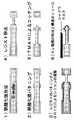
図2は本発明にかかわるマイクロ電源装置の主要部分である対向電極のマイクロマシニング技術を用いた作製例である。対向電極にはシリコン基板を用いる。図2(1)に示すように最初にSi基板全面に熱酸化膜を形成する。次いで図2(2)に示すようにウェットエッチングにより(希フッ酸等)によりエッチングを行い電極部となる箇所を残すようにする。次いで図2(c)に示すようにDRIEというドライエッチング手法により先端のシリコンの深彫エッチングを行う。次いで図2(4)に示すようにレジスト除去を行う。次いで図2(5)に示すようにTMAH溶液による異方性エッチングにより、対向電極側のメカニカルスイッチング先端部を形成する。最後に図2(6)に示すように、対向電極部とメカニカルスイッチにAu電極薄膜を形成して終了する。 FIG. 2 shows an example of manufacturing the counter electrode, which is the main part of the micro power supply device according to the present invention, using the micromachining technology. A silicon substrate is used for the counter electrode. As shown in FIG. 2A, a thermal oxide film is first formed on the entire surface of the Si substrate. Next, as shown in FIG. 2B, etching is performed by wet etching (dilute hydrofluoric acid or the like) to leave a portion to be an electrode portion. Next, as shown in FIG. 2C, deep etching of the tip silicon is performed by a dry etching technique called DRIE. Next, the resist is removed as shown in FIG. Next, as shown in FIG. 2 (5), a mechanical switching tip on the counter electrode side is formed by anisotropic etching with a TMAH solution. Finally, as shown in FIG. 2 (6), an Au electrode thin film is formed on the counter electrode portion and the mechanical switch, and the process is completed.
図3は、本発明にかかわるエレクトレット膜に電荷を帯電させる実験結果を示す。エレクトレット材料として、CYTOP(CTL−809M、旭硝子製)を用いている。CYTOPは、MEMS技術との整合性が良く、高電圧に耐え得る絶縁破壊強度を有しており、エレクトレット材料として高い性能をもつ。まず、20mm×20mmのシリコンウエハに、Au/Cr膜をスパッタにより形成した。次に、CYTOPをウエハに滴下し、スピンコートとベークを10回繰り返すことで厚さ16マイクロメートルのCYTOP膜を作製している。最後に、コロナ放電を用いて、CYTOP膜に電荷を注入し、エレクトレットを作製している。ここでは、放電電圧4.15kV、放電電流0.5mA、帯電電圧300V、帯電時間10分でコロナ放電を行っている。エレクトレットの表面電位分布を図3に示す。150Vから330Vの範囲で帯電されていることがわかる。 FIG. 3 shows the experimental results of charging the electret film according to the present invention with electric charges. CYTOP (CTL-809M, manufactured by Asahi Glass) is used as the electret material. CYTOP has good compatibility with MEMS technology, has a dielectric breakdown strength that can withstand high voltages, and has high performance as an electret material. First, an Au / Cr film was formed on a 20 mm × 20 mm silicon wafer by sputtering. Next, CYTOP is dropped onto the wafer, and spin coating and baking are repeated 10 times to produce a CYTOP film having a thickness of 16 micrometers. Lastly, an electric charge is injected into the CYTOP film using corona discharge to produce an electret. Here, corona discharge is performed with a discharge voltage of 4.15 kV, a discharge current of 0.5 mA, a charging voltage of 300 V, and a charging time of 10 minutes. The surface potential distribution of the electret is shown in FIG. It can be seen that charging is performed in the range of 150V to 330V.
本発明はIT機器の中でも特に消費電力が少なく、間欠的動作で作動するような機器の電源方式として有用である。その場で発電して、適切な電力量まで蓄電し、その場で一致に使いきるユビキタスIT機器用の電源を想定している。その際に、小さく機械的になることで、半導体整流方式のロスを克服しつつ、整流して直流電源として電力を供給できる。代表的な用途では、センサネットワークにおける機能性ノードの電源としての利用が見込まれる。本デバイスはMEMS(Micro Electromechanical Systems)技術で制作されるため、その特徴である一括処理による制作が可能である。このため、同じデバイスをアレイ状に作り込むことが可能で、一つ一つの発電量の小ささは数を作り込むことでカバーすることができる。機能性ノードは電力供給の心配がなければ、ホストが扱える範囲で多ければ多いほど、多くの情報を収集することができ、用途は広くなる。また、機能性ノードとしての利用では、本質的に同じデバイスが多く用いられるため、コストを抑えやすいことも有利な点である。 The present invention is particularly useful as a power supply system for devices that consume less power and operate intermittently among IT devices. A power supply for a ubiquitous IT device is assumed that generates electricity on the spot, stores it to an appropriate amount of power, and can be used consistently on the spot. At that time, by being small and mechanical, it can rectify and supply power as a DC power supply while overcoming the loss of the semiconductor rectification method. Typical applications are expected to be used as power sources for functional nodes in sensor networks. Since this device is produced by MEMS (Micro Electromechanical Systems) technology, it can be produced by batch processing which is a feature of the device. For this reason, it is possible to make the same device in an array, and the small amount of each power generation can be covered by making a number. As long as there is no concern about power supply, the functional node can collect more information and can be used more widely as the host can handle it. In addition, since the same device is used in many cases for use as a functional node, it is advantageous that the cost can be easily reduced.
1:ベース電極
2:エレクトレット膜
3:対向電極
4:ベース電極補完電極
5:対向電極支持構造
6:ベース電極側メカニカルスイッチ
7:ベース電極補完電極側メカニカルスイッチ
8:コンデンサ
9:負荷抵抗
10:ベース電極支持構造
11:ベース電極補完電極支持構造1: Base electrode 2: Electret film 3: Counter electrode 4: Base electrode complementary electrode 5: Counter electrode support structure 6: Base electrode side mechanical switch 7: Base electrode complementary electrode side mechanical switch 8: Capacitor 9: Load resistance 10: Base Electrode support structure 11: Base electrode complementary electrode support structure
Claims (1)
Translated fromJapanesePriority Applications (1)
| Application Number | Priority Date | Filing Date | Title |
|---|---|---|---|
| JP2008029648AJP2009171821A (en) | 2008-01-10 | 2008-01-10 | Micro power generator |
Applications Claiming Priority (1)
| Application Number | Priority Date | Filing Date | Title |
|---|---|---|---|
| JP2008029648AJP2009171821A (en) | 2008-01-10 | 2008-01-10 | Micro power generator |
Publications (1)
| Publication Number | Publication Date |
|---|---|
| JP2009171821Atrue JP2009171821A (en) | 2009-07-30 |
Family
ID=40972353
Family Applications (1)
| Application Number | Title | Priority Date | Filing Date |
|---|---|---|---|
| JP2008029648APendingJP2009171821A (en) | 2008-01-10 | 2008-01-10 | Micro power generator |
Country Status (1)
| Country | Link |
|---|---|
| JP (1) | JP2009171821A (en) |
Cited By (5)
| Publication number | Priority date | Publication date | Assignee | Title |
|---|---|---|---|---|
| JP2012137428A (en)* | 2010-12-27 | 2012-07-19 | Asahi Glass Co Ltd | Piping monitoring system |
| JP2012152010A (en)* | 2011-01-19 | 2012-08-09 | Seiko Epson Corp | Power generator |
| US8564169B2 (en) | 2010-08-23 | 2013-10-22 | Seiko Epson Corporation | Electrostatic induction generation device and electrostatic induction generation apparatus having a movable electrode formed between a first fixed electrode substrate and a second fixed electrode substrate |
| JP2015505663A (en)* | 2012-02-01 | 2015-02-23 | アルダナック メフメト セルハンARDANUC, Mehmet Serhan | Energy harvesting method and apparatus using intrinsic voltage difference between metal joints |
| JP2018526960A (en)* | 2015-09-04 | 2018-09-13 | コーニンクレッカ フィリップス エヌ ヴェKoninklijke Philips N.V. | Power generation device and power generation method |
- 2008
- 2008-01-10JPJP2008029648Apatent/JP2009171821A/enactivePending
Cited By (5)
| Publication number | Priority date | Publication date | Assignee | Title |
|---|---|---|---|---|
| US8564169B2 (en) | 2010-08-23 | 2013-10-22 | Seiko Epson Corporation | Electrostatic induction generation device and electrostatic induction generation apparatus having a movable electrode formed between a first fixed electrode substrate and a second fixed electrode substrate |
| JP2012137428A (en)* | 2010-12-27 | 2012-07-19 | Asahi Glass Co Ltd | Piping monitoring system |
| JP2012152010A (en)* | 2011-01-19 | 2012-08-09 | Seiko Epson Corp | Power generator |
| JP2015505663A (en)* | 2012-02-01 | 2015-02-23 | アルダナック メフメト セルハンARDANUC, Mehmet Serhan | Energy harvesting method and apparatus using intrinsic voltage difference between metal joints |
| JP2018526960A (en)* | 2015-09-04 | 2018-09-13 | コーニンクレッカ フィリップス エヌ ヴェKoninklijke Philips N.V. | Power generation device and power generation method |
Similar Documents
| Publication | Publication Date | Title |
|---|---|---|
| Zhang et al. | Employing a MEMS plasma switch for conditioning high-voltage kinetic energy harvesters | |
| JP5855602B2 (en) | Electrostatic induction type electromechanical transducer and nanotweezers | |
| Arakawa et al. | Micro seismic power generator using electret polymer film | |
| Boisseau et al. | Electrostatic conversion for vibration energy harvesting | |
| Honma et al. | Improvement of energy conversion effectiveness and maximum output power of electrostatic induction-type MEMS energy harvesters by using symmetric comb-electrode structures | |
| JP5676377B2 (en) | Electret film and vibration power generation element using the same | |
| JP5611565B2 (en) | Piezoelectric vibration generator and power generator using the same | |
| EP3098866B1 (en) | Piezoelectric power generation module and remote controller | |
| JP2009171821A (en) | Micro power generator | |
| JP6047177B2 (en) | Energy harvesting method and apparatus using intrinsic voltage difference between metal joints | |
| US20210119555A1 (en) | Vibrational Energy Harvester Device | |
| Liu et al. | Sandwich structured electrostatic/electrets parallel-plate power generator for low acceleration and low frequency vibration energy harvesting | |
| WO2017191436A1 (en) | An energy harvester | |
| JP2016185022A (en) | Power generator | |
| JP5226907B1 (en) | Vibration power generator, vibration power generation device, and electrical equipment and communication device equipped with vibration power generation device | |
| JP2014226003A (en) | Vibration power generator | |
| JP5573624B2 (en) | Power generation device and electronic device | |
| CN112042105B (en) | Vibration power generation device | |
| JP2019198160A (en) | Vibration power generation element and vibration power generator | |
| JP2014230398A (en) | Electrostatic transformer | |
| JP5807743B2 (en) | POWER GENERATION DEVICE, ELECTRONIC DEVICE, MOBILE DEVICE, AND POWER GENERATION DEVICE CONTROL METHOD | |
| Tao et al. | A three-dimensional electrostatic/electret micro power generator for low acceleration and low frequency vibration energy harvesting | |
| JP2014075951A (en) | Electret electrode, vibration power generator and vibration power generation device using the same, communication apparatus mounted with vibration power generation device, and manufacturing method of electret electrode | |
| JP5307955B1 (en) | Micro-electromechanical generator and electrical equipment using the same | |
| JP7156649B2 (en) | Vibration power generation element and vibration power generation device |