JP2009170405A - Energy management module and drive unit - Google Patents
Energy management module and drive unitDownload PDFInfo
- Publication number
- JP2009170405A JP2009170405AJP2008262705AJP2008262705AJP2009170405AJP 2009170405 AJP2009170405 AJP 2009170405AJP 2008262705 AJP2008262705 AJP 2008262705AJP 2008262705 AJP2008262705 AJP 2008262705AJP 2009170405 AJP2009170405 AJP 2009170405A
- Authority
- JP
- Japan
- Prior art keywords
- fuel
- concentration
- signal
- solution
- supply
- Prior art date
- Legal status (The legal status is an assumption and is not a legal conclusion. Google has not performed a legal analysis and makes no representation as to the accuracy of the status listed.)
- Pending
Links
Images


Classifications
- H—ELECTRICITY
- H01—ELECTRIC ELEMENTS
- H01M—PROCESSES OR MEANS, e.g. BATTERIES, FOR THE DIRECT CONVERSION OF CHEMICAL ENERGY INTO ELECTRICAL ENERGY
- H01M8/00—Fuel cells; Manufacture thereof
- H01M8/04—Auxiliary arrangements, e.g. for control of pressure or for circulation of fluids
- H01M8/04082—Arrangements for control of reactant parameters, e.g. pressure or concentration
- H01M8/04201—Reactant storage and supply, e.g. means for feeding, pipes
- H—ELECTRICITY
- H01—ELECTRIC ELEMENTS
- H01M—PROCESSES OR MEANS, e.g. BATTERIES, FOR THE DIRECT CONVERSION OF CHEMICAL ENERGY INTO ELECTRICAL ENERGY
- H01M8/00—Fuel cells; Manufacture thereof
- H01M8/04—Auxiliary arrangements, e.g. for control of pressure or for circulation of fluids
- H—ELECTRICITY
- H01—ELECTRIC ELEMENTS
- H01M—PROCESSES OR MEANS, e.g. BATTERIES, FOR THE DIRECT CONVERSION OF CHEMICAL ENERGY INTO ELECTRICAL ENERGY
- H01M10/00—Secondary cells; Manufacture thereof
- H01M10/42—Methods or arrangements for servicing or maintenance of secondary cells or secondary half-cells
- H01M10/425—Structural combination with electronic components, e.g. electronic circuits integrated to the outside of the casing
- H—ELECTRICITY
- H01—ELECTRIC ELEMENTS
- H01M—PROCESSES OR MEANS, e.g. BATTERIES, FOR THE DIRECT CONVERSION OF CHEMICAL ENERGY INTO ELECTRICAL ENERGY
- H01M16/00—Structural combinations of different types of electrochemical generators
- H01M16/003—Structural combinations of different types of electrochemical generators of fuel cells with other electrochemical devices, e.g. capacitors, electrolysers
- H01M16/006—Structural combinations of different types of electrochemical generators of fuel cells with other electrochemical devices, e.g. capacitors, electrolysers of fuel cells with rechargeable batteries
- H—ELECTRICITY
- H01—ELECTRIC ELEMENTS
- H01M—PROCESSES OR MEANS, e.g. BATTERIES, FOR THE DIRECT CONVERSION OF CHEMICAL ENERGY INTO ELECTRICAL ENERGY
- H01M8/00—Fuel cells; Manufacture thereof
- H01M8/04—Auxiliary arrangements, e.g. for control of pressure or for circulation of fluids
- H01M8/04298—Processes for controlling fuel cells or fuel cell systems
- H01M8/04313—Processes for controlling fuel cells or fuel cell systems characterised by the detection or assessment of variables; characterised by the detection or assessment of failure or abnormal function
- H01M8/0432—Temperature; Ambient temperature
- H01M8/04365—Temperature; Ambient temperature of other components of a fuel cell or fuel cell stacks
- H—ELECTRICITY
- H01—ELECTRIC ELEMENTS
- H01M—PROCESSES OR MEANS, e.g. BATTERIES, FOR THE DIRECT CONVERSION OF CHEMICAL ENERGY INTO ELECTRICAL ENERGY
- H01M8/00—Fuel cells; Manufacture thereof
- H01M8/04—Auxiliary arrangements, e.g. for control of pressure or for circulation of fluids
- H01M8/04298—Processes for controlling fuel cells or fuel cell systems
- H01M8/04313—Processes for controlling fuel cells or fuel cell systems characterised by the detection or assessment of variables; characterised by the detection or assessment of failure or abnormal function
- H01M8/0444—Concentration; Density
- H01M8/04447—Concentration; Density of anode reactants at the inlet or inside the fuel cell
- H—ELECTRICITY
- H01—ELECTRIC ELEMENTS
- H01M—PROCESSES OR MEANS, e.g. BATTERIES, FOR THE DIRECT CONVERSION OF CHEMICAL ENERGY INTO ELECTRICAL ENERGY
- H01M8/00—Fuel cells; Manufacture thereof
- H01M8/04—Auxiliary arrangements, e.g. for control of pressure or for circulation of fluids
- H01M8/04298—Processes for controlling fuel cells or fuel cell systems
- H01M8/04313—Processes for controlling fuel cells or fuel cell systems characterised by the detection or assessment of variables; characterised by the detection or assessment of failure or abnormal function
- H01M8/04537—Electric variables
- H01M8/04544—Voltage
- H01M8/04559—Voltage of fuel cell stacks
- H—ELECTRICITY
- H01—ELECTRIC ELEMENTS
- H01M—PROCESSES OR MEANS, e.g. BATTERIES, FOR THE DIRECT CONVERSION OF CHEMICAL ENERGY INTO ELECTRICAL ENERGY
- H01M8/00—Fuel cells; Manufacture thereof
- H01M8/04—Auxiliary arrangements, e.g. for control of pressure or for circulation of fluids
- H01M8/04298—Processes for controlling fuel cells or fuel cell systems
- H01M8/04313—Processes for controlling fuel cells or fuel cell systems characterised by the detection or assessment of variables; characterised by the detection or assessment of failure or abnormal function
- H01M8/04537—Electric variables
- H01M8/04574—Current
- H01M8/04589—Current of fuel cell stacks
- H—ELECTRICITY
- H01—ELECTRIC ELEMENTS
- H01M—PROCESSES OR MEANS, e.g. BATTERIES, FOR THE DIRECT CONVERSION OF CHEMICAL ENERGY INTO ELECTRICAL ENERGY
- H01M8/00—Fuel cells; Manufacture thereof
- H01M8/04—Auxiliary arrangements, e.g. for control of pressure or for circulation of fluids
- H01M8/04298—Processes for controlling fuel cells or fuel cell systems
- H01M8/04694—Processes for controlling fuel cells or fuel cell systems characterised by variables to be controlled
- H01M8/04791—Concentration; Density
- H01M8/04798—Concentration; Density of fuel cell reactants
- H—ELECTRICITY
- H01—ELECTRIC ELEMENTS
- H01M—PROCESSES OR MEANS, e.g. BATTERIES, FOR THE DIRECT CONVERSION OF CHEMICAL ENERGY INTO ELECTRICAL ENERGY
- H01M8/00—Fuel cells; Manufacture thereof
- H01M8/04—Auxiliary arrangements, e.g. for control of pressure or for circulation of fluids
- H01M8/04298—Processes for controlling fuel cells or fuel cell systems
- H01M8/04992—Processes for controlling fuel cells or fuel cell systems characterised by the implementation of mathematical or computational algorithms, e.g. feedback control loops, fuzzy logic, neural networks or artificial intelligence
- H—ELECTRICITY
- H01—ELECTRIC ELEMENTS
- H01M—PROCESSES OR MEANS, e.g. BATTERIES, FOR THE DIRECT CONVERSION OF CHEMICAL ENERGY INTO ELECTRICAL ENERGY
- H01M8/00—Fuel cells; Manufacture thereof
- H01M8/24—Grouping of fuel cells, e.g. stacking of fuel cells
- H—ELECTRICITY
- H01—ELECTRIC ELEMENTS
- H01M—PROCESSES OR MEANS, e.g. BATTERIES, FOR THE DIRECT CONVERSION OF CHEMICAL ENERGY INTO ELECTRICAL ENERGY
- H01M8/00—Fuel cells; Manufacture thereof
- H01M8/10—Fuel cells with solid electrolytes
- H01M8/1009—Fuel cells with solid electrolytes with one of the reactants being liquid, solid or liquid-charged
- H01M8/1011—Direct alcohol fuel cells [DAFC], e.g. direct methanol fuel cells [DMFC]
- Y—GENERAL TAGGING OF NEW TECHNOLOGICAL DEVELOPMENTS; GENERAL TAGGING OF CROSS-SECTIONAL TECHNOLOGIES SPANNING OVER SEVERAL SECTIONS OF THE IPC; TECHNICAL SUBJECTS COVERED BY FORMER USPC CROSS-REFERENCE ART COLLECTIONS [XRACs] AND DIGESTS
- Y02—TECHNOLOGIES OR APPLICATIONS FOR MITIGATION OR ADAPTATION AGAINST CLIMATE CHANGE
- Y02E—REDUCTION OF GREENHOUSE GAS [GHG] EMISSIONS, RELATED TO ENERGY GENERATION, TRANSMISSION OR DISTRIBUTION
- Y02E60/00—Enabling technologies; Technologies with a potential or indirect contribution to GHG emissions mitigation
- Y02E60/10—Energy storage using batteries
- Y—GENERAL TAGGING OF NEW TECHNOLOGICAL DEVELOPMENTS; GENERAL TAGGING OF CROSS-SECTIONAL TECHNOLOGIES SPANNING OVER SEVERAL SECTIONS OF THE IPC; TECHNICAL SUBJECTS COVERED BY FORMER USPC CROSS-REFERENCE ART COLLECTIONS [XRACs] AND DIGESTS
- Y02—TECHNOLOGIES OR APPLICATIONS FOR MITIGATION OR ADAPTATION AGAINST CLIMATE CHANGE
- Y02E—REDUCTION OF GREENHOUSE GAS [GHG] EMISSIONS, RELATED TO ENERGY GENERATION, TRANSMISSION OR DISTRIBUTION
- Y02E60/00—Enabling technologies; Technologies with a potential or indirect contribution to GHG emissions mitigation
- Y02E60/30—Hydrogen technology
- Y02E60/50—Fuel cells
Landscapes
- Engineering & Computer Science (AREA)
- Life Sciences & Earth Sciences (AREA)
- Sustainable Development (AREA)
- Sustainable Energy (AREA)
- Chemical & Material Sciences (AREA)
- Chemical Kinetics & Catalysis (AREA)
- Electrochemistry (AREA)
- General Chemical & Material Sciences (AREA)
- Manufacturing & Machinery (AREA)
- Health & Medical Sciences (AREA)
- Microelectronics & Electronic Packaging (AREA)
- Artificial Intelligence (AREA)
- Automation & Control Theory (AREA)
- Computing Systems (AREA)
- Evolutionary Computation (AREA)
- Fuzzy Systems (AREA)
- Medical Informatics (AREA)
- Software Systems (AREA)
- Theoretical Computer Science (AREA)
- Fuel Cell (AREA)
Abstract
Description
Translated fromJapanese本発明は、負荷を駆動する駆動装置に関し、特に、燃料電池を含む駆動装置と、それに用いられるエネルギー管理モジュールに関するものである。 The present invention relates to a drive device for driving a load, and more particularly to a drive device including a fuel cell and an energy management module used therefor.
燃料電池は、非常用予備発電、輸送可能な電源システム、または携帯型電子装置等に広く用いられている。各燃料電池は、膜電極アセンブリ(MEA)を含む。一定濃度の燃料がMEAの陽極に提供され、適量の酸素がMEAの陰極に提供された時、陽極と陰極間の電位差が化学反応により発生される。そして、燃料電池が電力を外部負荷に提供する。燃料電池による生成物は、二酸化炭素と水であり、有機物は生成されない。よって、燃料電池は、環境にやさしい。従来の燃料電池は、メタノール水溶液を発電用燃料とするダイレクトメタノール型燃料電池(DMFC)を含む。 Fuel cells are widely used in emergency standby power generation, transportable power supply systems, portable electronic devices, and the like. Each fuel cell includes a membrane electrode assembly (MEA). When a constant concentration of fuel is provided to the MEA anode and an appropriate amount of oxygen is provided to the MEA cathode, a potential difference between the anode and the cathode is generated by a chemical reaction. The fuel cell then provides power to the external load. The products produced by the fuel cell are carbon dioxide and water, and no organic matter is produced. Therefore, the fuel cell is environmentally friendly. A conventional fuel cell includes a direct methanol fuel cell (DMFC) using a methanol aqueous solution as a fuel for power generation.
しかし、従来のDMFCに用いられるメタノール水溶液の濃度は、既定値で制御されてメタノールクロスオーバーを防止しているため、MEAの発電効率を低下させる可能性がある。メタノール水溶液のこの既定値は、DMFCに用いられるMEAの性質によって決まり、通常、10%(vol%)を超えない。また、DMFCは、操作温度と環境温度によって影響され易く、その操作温度と環境温度が高すぎた場合(通常、60℃の温度以上)、発電効率が低下する可能性がある。 However, since the concentration of the aqueous methanol solution used in the conventional DMFC is controlled at a predetermined value to prevent methanol crossover, there is a possibility of reducing the power generation efficiency of the MEA. This default value for aqueous methanol depends on the nature of the MEA used in the DMFC and usually does not exceed 10% (vol%). In addition, the DMFC is easily affected by the operating temperature and the environmental temperature, and if the operating temperature and the environmental temperature are too high (usually a temperature of 60 ° C. or higher), the power generation efficiency may be reduced.
DMFCの反応は、下記の公式(1)〜(3)に基づいて発生する。 The DMFC reaction occurs based on the following formulas (1) to (3).
(1)陽極で: CH3OH+H2O → 6H++6e−+CO2(1) At the anode: CH3 OH + H2 O → 6H+ + 6e− + CO2
(2)陰極で: 1.5O2+6H++6e− →3H2O(2) At the cathode: 1.5O2 + 6H+ + 6e− → 3H2 O
(3)全反応で: CH3OH+1.5O2→ CO2+2H2O(3) In all reactions: CH3 OH + 1.5O2 → CO2 + 2H2 O
全ての反応から分るように、水はDMFCの操作中に生成される。しかし、水は、反応中に蒸発する可能性があり、蒸発した水の量は、環境温度と操作温度などの要因により、DMFCの操作中のその生成量より多い可能性がある。また、メタノール水溶液のメタノールの量は、DMFCの反応時間が増加した時、減少され、メタノール水溶液の濃度は、反応時間が増加した時、減少される。メタノール水溶液の濃度が低すぎた場合、陽極で発生された水素イオンは、減少し、メタノールと水の量は、DMFCの連続的な化学反応を持続するために増加されてDMFCの連続運転を維持する。 As can be seen from all reactions, water is produced during operation of the DMFC. However, water can evaporate during the reaction and the amount of evaporated water can be greater than its production during operation of the DMFC due to factors such as environmental temperature and operating temperature. Also, the amount of methanol in the aqueous methanol solution is decreased when the DMFC reaction time is increased, and the concentration of the aqueous methanol solution is decreased when the reaction time is increased. If the concentration of the aqueous methanol solution is too low, the hydrogen ions generated at the anode will decrease and the amount of methanol and water will be increased to sustain the continuous chemical reaction of the DMFC to maintain the continuous operation of the DMFC. To do.
駆動装置とエネルギー管理モジュールを提供する。 Provide drive and energy management module.
負荷を駆動する駆動装置であって、二次電池、燃料電池、燃料補給装置と、二次電池、燃料電池と、燃料補給装置に接続されたエネルギー管理モジュールを含み、電流信号を負荷に発生し、燃料電池の電気信号と液位信号に基づいて、第1と第2補給信号を燃料供給装置に発生する。エネルギー管理モジュールは、燃料供給装置を駆動し、燃料溶液を燃料電池に補給する。 A drive device for driving a load, including a secondary battery, a fuel cell, a fuel supply device, a secondary battery, a fuel cell, and an energy management module connected to the fuel supply device, and generating a current signal to the load Based on the electric signal and the liquid level signal of the fuel cell, the first and second replenishment signals are generated in the fuel supply device. The energy management module drives the fuel supply device to replenish the fuel cell with the fuel solution.
二次電池、燃料電池と、燃料補給装置に接続され、負荷を駆動して、燃料電池に補給するエネルギー管理モジュールが提供される。エネルギー管理モジュールは、処理ユニットと、温度検出ユニットを含み、温度検出ユニットは、燃料電池の温度状態に基づいて処理ユニットの温度信号を提供し、処理ユニットは、燃料電池の電気信号、液位信号と、温度信号に基づいて、第1と第2信号を燃料供給装置に発生する。 An energy management module is provided that is connected to a secondary battery, a fuel cell, and a fuel supply device, drives a load, and supplies the fuel cell. The energy management module includes a processing unit and a temperature detection unit, wherein the temperature detection unit provides a temperature signal of the processing unit based on the temperature state of the fuel cell, and the processing unit includes an electric signal of the fuel cell, a liquid level signal And the first and second signals are generated in the fuel supply device based on the temperature signal.
二次電池、燃料電池、燃料補給装置と、二次電池、燃料電池と、燃料補給装置に接続されたエネルギー管理モジュールを含み、電流信号を負荷に発生する、負荷を駆動するもう1つの駆動装置が提供される。駆動装置は、燃料濃度信号と燃料電池からの液位信号に基づいて、第1と第2信号を燃料供給装置に発生し、燃料補給装置を駆動して燃料電池に燃料補給を提供する。 Another drive device for driving a load, including a secondary battery, a fuel cell, a fuel supply device, a secondary battery, a fuel cell, and an energy management module connected to the fuel supply device, and generating a current signal in the load Is provided. The driving device generates first and second signals in the fuel supply device based on the fuel concentration signal and the liquid level signal from the fuel cell, and drives the fuel supply device to provide fuel supply to the fuel cell.
二次電池、燃料電池と、燃料補給装置に接続され、負荷を駆動し、燃料補給装置に補給するもう1つのエネルギー管理モジュールが提供される。エネルギー管理モジュールは、処理ユニットを含み、燃料電池からの燃料濃度信号と液位信号に基づいて第1と第2信号を燃料補給装置に発生する。 A secondary battery, a fuel cell, and another energy management module connected to the refueling device, driving a load and refueling the refueling device are provided. The energy management module includes a processing unit, and generates a first signal and a second signal to the fuel supply device based on the fuel concentration signal and the liquid level signal from the fuel cell.
本発明の駆動装置のエネルギー管理モジュールは、その中の燃料電池安定した制御と管理をすることができ、燃料電池とその中の燃料補給装置の設置によって、純燃料と水分の補給をする。よって、燃料電池の安定した発電効率を駆動装置に提供し、長時間操作することができる。また、用いられる燃料補給装置は、一般的なタンクと定量ポンプなどの装置を用いているだけで、燃料電池の燃料溶液の濃度は、エネルギー管理モジュールによって制御され、管理されることができる。よって、簡易化したシステム構成と簡単な操作などの利点を有する。よって、人工的に燃料電池の燃料溶液を調整する不便と可能な問題が防げられる。 The energy management module of the drive device of the present invention can perform stable control and management of the fuel cell therein, and replenishes pure fuel and moisture by installing the fuel cell and the fuel supply device therein. Therefore, the stable power generation efficiency of the fuel cell can be provided to the drive device and operated for a long time. Further, the fuel replenishing device used only uses devices such as a general tank and a metering pump, and the concentration of the fuel solution in the fuel cell can be controlled and managed by the energy management module. Therefore, there are advantages such as a simplified system configuration and simple operation. Therefore, the inconvenience and possible problem of artificially adjusting the fuel solution of the fuel cell can be prevented.
本発明についての目的、特徴、長所が一層明確に理解されるよう、以下に実施形態を例示し、図面を参照にしながら、詳細に説明する。 In order that the objects, features, and advantages of the present invention will be more clearly understood, embodiments will be described below in detail with reference to the drawings.
図1は、駆動システムの実施例の概略図である。駆動システム100は、駆動装置110と負荷120を含む。負荷120は、駆動装置110によって提供された電源信号を受け、関連する機能を実行する。この実施例では、負荷120は、ファン、ポンプ、加熱器、またはその他の電気機器である。 FIG. 1 is a schematic diagram of an embodiment of a drive system. The
図2は、駆動装置の実施例の概略図である。駆動装置110は、二次電池210、燃料電池220、エネルギー管理モジュール230と、燃料補給装置240を含む。二次電池210は、例えば、リチウムイオン二次電池、ニッカド電池、またはニッケル水素電池などの再充電可能電池である。エネルギー管理モジュール230は、二次電池210、燃料電池220と、燃料補給装置240に接続され、二次電池210によって発生された電気信号SSECと、燃料電池220によって発生された電気信号SFCとに基づいて負荷120を駆動する。エネルギー管理モジュール230はまた、燃料電池220からの電気信号SFCと液位信号SLに基づいて、2つの補給信号SHLSとSLLSを異なる燃料濃度の2つの燃料補給ユニット(図示されていない)にそれぞれ発生させることで、燃料補給装置240内の燃料ポンプ(図示されていない)を駆動し、異なる濃度の燃料を燃料電池220に補給する。よって、燃料電池220は、純燃料(pure fuel)と水で補給されて電気発生し、駆動装置110の安定した長時間の運転を維持することができる。この実施例では、電気信号SSECとSFC、液位信号SL、補給信号SHLSとSLLSは、例えば電圧信号または電流信号からなることができる。FIG. 2 is a schematic diagram of an embodiment of a drive device. The
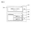
図3は、エネルギー管理モジュールの実施例の概略図である。図3に示されるように、エネルギー管理モジュール230は、電圧変換ユニット310と電流発生ユニット320を含む。電圧変換ユニット310は、電気信号SSECまたはSFCを変換して電圧信号SDCを発生し、電流発生ユニット320は、電圧信号SDCを受け、信号グループSCG1に基づいて異なる電流を負荷に発生する。この実施例では、エネルギー管理モジュール230は、処理ユニット330、スイッチユニット340と、温度検出ユニット350を更に含む。処理ユニット330は、検出回路331とマイクロプロセッサ332を含む。温度検出ユニット350は、燃料電池の操作温度、または燃料電池の環境温度を検出し、温度信号STを処理ユニット330のマイクロプロセッサ332に提供することができる。検出回路331は、燃料電池からの電気信号SFCを検出し、対応する電圧信号または電流信号を発生し、燃料電池の電気状態を表す。マイクロプロセッサ332は、検出回路331に接続され、上述の電圧信号、または電流信号を受ける。よって、マイクロプロセッサ332は、上述の電気信号SFC、液位信号SLと、温度信号STに基づいて、補給信号SLLCとSHLCを燃料補給装置240(図2を参照)に発生することができるため、燃料補給装置240は、補給燃料を燃料電池に提供することができる。FIG. 3 is a schematic diagram of an embodiment of an energy management module. As shown in FIG. 3, the
この実施例では、処理ユニット330は、燃料電池の状態(e.g.電気信号SFC、液位信号SLと、温度信号ST)に基づいて、信号グループSCG1を電流発生ユニット320に提供する。よって、電流発生ユニット320は、燃料電池の状態に基づいて異なる電流を負荷に提供することができる。提供された電流信号は、燃料電池内の燃料消費に比例する。また、処理ユニット330は、燃料電池の状態に基づいて信号グループSCG2をスイッチユニット340に更に提供する。よって、スイッチユニット340は、上述の燃料電池の状態に基づいて、電気信号SFCを電圧変換ユニット310に伝送し、処理ユニット330からの補給信号SLLCとSHLCに基づいて、燃料補給装置240(図2を参照)によって燃料と水の補給を燃料電池に提供する。よって、電流発生ユニット320で受けた電圧信号SDCを安定させ、安定した電流を負荷に提供する。In this embodiment, the
図4は、燃料電池220の実施例の概略図であり、膜電極アセンブリ(MEA)モジュール410と燃料蓄積装置420を含んでいる。燃料蓄積装置420は、MEAモジュール410に接続され、MEAモジュール410の電気発生用の燃料溶液の保存と提供をする。燃料蓄積装置420は、分流と合流装置(図示されていない)を含んで、MEAモジュール410内に流れる燃料溶液の伝送と回収をする。燃料蓄積装置は、例えば、そこに設置された液位センサ422を有するタンクであることができる。液位センサ422は、燃料蓄積装置の液位状態に基づいて、液位信号SLをエネルギー管理モジュール230の処理ユニット330のマイクロプロセッサ332に提供する。燃料蓄積装置420内の液位は、例えば、最高液位(HH)、高液位(H)、低液位(L)と、最低液位(LL)を含む高い位置から低い位置に定義される。最高液位と最低液位は、ほぼ満杯の液位とほぼ空の液位にそれぞれ対応し、高液位と低液位は、上述の2つの液位の間に位置され、燃料溶液の濃度によって決まる。一般的に、高液位と低液位間の液位の燃料溶液の濃度は、MEAモジュール410の電気発生を安定させることができる燃料溶液の濃度である。DMFCの燃料電池を例にすると、好ましいメタノール水溶液の濃度は、約3〜10%であり、その中に用いられるMEAモジュールの電気発生を安定させる。よって、エネルギー管理モジュール230の処理ユニット330は、燃料電池の燃料蓄積装置の液位状態を得ることができ、液位状態と燃料電池からの電気信号の状態に基づいて、適当な補給信号SLLCとSHLCを燃料補給装置240に発生する。FIG. 4 is a schematic diagram of an embodiment of a
図5は、燃料補給装置の実施例の概略図である。図5に示すように、燃料補給装置240は、第1濃度燃料補給ユニット510と第2濃度燃料補給ユニット514を含む。第1濃度燃料補給ユニット510は、補給信号SHLCに基づいて一定量の第1濃度燃料溶液を燃料電池220の燃料蓄積装置420に提供することができ、第2濃度燃料補給ユニット514は、補給信号SLLCに基づいて一定量の第2濃度燃料溶液を燃料電池220の燃料蓄積装置420に提供することができる。第1濃度燃料溶液は、第2濃度燃料溶液の濃度より高い燃料濃度を有し、第1濃度燃料補給ユニット510と第2濃度燃料補給ユニット514は単独に、または同時に、または順次に操作して燃料蓄積装置420に燃料溶液補給を提供することができる。第1濃度燃料補給ユニット510と第2濃度燃料補給ユニット514は、燃料蓄積装置420より大きい体積を有するタンクであることができ、これは、長時間の補給に有益である。第1補給ポンプ512は、第1濃度燃料補給ユニット510内に設置され、補給信号SHLSに基づいて第1濃度燃料溶液を補給する。第2補給ポンプ514は、第2濃度燃料補給ユニット514内に設置され、補給信号SLLSに基づいて第2濃度燃料溶液を補給する。第1と第2補給ポンプ512と514は、例えば定量ポンプであることができる。FIG. 5 is a schematic view of an embodiment of a fuel supply device. As shown in FIG. 5, the
1つの実施例では、第1濃度燃料溶液は、通常50%(vol%)を超える濃度を有し、これは、主に補給燃料溶液の損耗の純燃料量(水を含まない)である。第2濃度燃料溶液は、通常10%(vol%)より少ない濃度を有し、この主な作用は、燃料溶液から蒸発された水分を補給する。好ましい実施例では、第1濃度燃料溶液は、通常100%(純燃料溶液)の濃度を有し、第2濃度燃料溶液は、約3〜10%の濃度を有して水分の補給を提供し、燃料電池の燃料と水を補給する。この実施例では、燃料電池はDMFCであることができ、電気発生燃料溶液、第1濃度燃料溶液と、第2濃度燃料溶液は、前述の濃度のメタノール水溶液、または純メタノール溶液である。 In one embodiment, the first concentration fuel solution typically has a concentration greater than 50% (vol%), which is primarily the pure fuel amount (not including water) of wear of the make-up fuel solution. The second concentration fuel solution typically has a concentration of less than 10% (vol%), and this main action replenishes the water evaporated from the fuel solution. In a preferred embodiment, the first concentration fuel solution typically has a concentration of 100% (pure fuel solution) and the second concentration fuel solution has a concentration of about 3-10% to provide replenishment of moisture. Refuel the fuel cell with water. In this embodiment, the fuel cell may be a DMFC, and the electricity generating fuel solution, the first concentration fuel solution, and the second concentration fuel solution are the methanol aqueous solution or the pure methanol solution having the aforementioned concentration.
図6は、制御方法の概略流れ図である。制御方法600では、負荷は燃料電池によって駆動され、燃料電池は、エネルギー管理モジュールによって制御された燃料電池の燃料溶液補給を用いることで、長時間かつ安定した操作ができる。図6に表されるように、二次電池はまず、図3に表された回路(表示されていない)と異なる回路によって駆動されて、第2濃度補給ユニットの補給ポンプを駆動し、第2濃度燃料溶液を燃料電池の燃料蓄積装置の最高液位(HH)までポンプする。この時、第2濃度燃料溶液は、MEAモジュールを駆動して電気を発生することができ、その機能を安定させる(ステップS610)。このステップでは、二次電池の駆動前に、MEAモジュールと燃料蓄積装置は、空でその中に燃料溶液が存在しない。 FIG. 6 is a schematic flowchart of the control method. In the
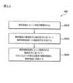
続いて、燃料電池を駆動した後、MEAモジュールは、電気信号をエネルギー管理モジュールの処理ユニットに発生し、燃料電池の燃料蓄積装置の液位センサは、液位信号を処理ユニットに発生し、エネルギー管理モジュールの温度検出ユニットは、温度信号を処理ユニットに発生する。よって、処理ユニットは、上述の電気信号、液位信号と、温度信号に基づいて第1補給信号と第2補給信号を燃料補給装置に発生する(ステップS620)。 Subsequently, after driving the fuel cell, the MEA module generates an electrical signal in the processing unit of the energy management module, and the liquid level sensor of the fuel storage device of the fuel cell generates a liquid level signal in the processing unit, The temperature detection unit of the management module generates a temperature signal to the processing unit. Therefore, the processing unit generates the first replenishment signal and the second replenishment signal to the fuel replenishing device based on the above-described electrical signal, liquid level signal, and temperature signal (step S620).
続いて、第1濃度燃料補給ユニットは、第1補給信号に基づいて第1定量の第1濃度燃料溶液を燃料電池の燃料蓄積装置内に補給する。第2濃度燃料補給ユニットは、第2補給信号に基づいて第2定量の第2濃度燃料溶液を燃料電池の燃料蓄積装置内に補給する。第1濃度燃料溶液は、第2濃度燃料溶液より高い燃料濃度を有する。第1ポンプは、第1濃度燃料供給ユニットに設置され、第2ポンプは、第2濃度燃料供給ユニットに設置されて、第1補給信号と第2補給信号に基づいて、第1と第2燃料溶液をそれぞれ補給する。よって、燃料電池の燃料蓄積装置の液位と燃料溶液の濃度が安定して維持され、燃料電池の安定した電気発生が提供される(ステップS630)。 Subsequently, the first concentration fuel supply unit supplies a first fixed amount of the first concentration fuel solution into the fuel storage device of the fuel cell based on the first supply signal. The second concentration fuel supply unit supplies a second fixed amount of the second concentration fuel solution into the fuel storage device of the fuel cell based on the second supply signal. The first concentration fuel solution has a higher fuel concentration than the second concentration fuel solution. The first pump is installed in the first concentration fuel supply unit, and the second pump is installed in the second concentration fuel supply unit, and the first and second fuels are based on the first supply signal and the second supply signal. Replenish each solution. Therefore, the liquid level of the fuel storage device of the fuel cell and the concentration of the fuel solution are stably maintained, and stable electricity generation of the fuel cell is provided (step S630).
図7は、上述のステップS620に示された処理信号に第1と第2補給信号を発生する実施例を表す流れ図である。まず、処理ユニットの検出回路は、燃料電池からの電気信号に基づいて、電圧信号と電流信号を順次に発生する(ステップS710)。 FIG. 7 is a flowchart showing an embodiment in which the first and second supply signals are generated for the processing signal shown in step S620 described above. First, the detection circuit of the processing unit sequentially generates a voltage signal and a current signal based on the electric signal from the fuel cell (step S710).
続いて、処理ユニットのマイクロプロセッサは、温度検出ユニットからの電圧信号と温度信号に基づいて、燃料電池の発電効率値を得る(ステップS720)。発電効率値は、上述の電圧信号と温度信号をマイクロプロセッサ内に保存された発電効率表と照合することで得られることができる。 Subsequently, the microprocessor of the processing unit obtains the power generation efficiency value of the fuel cell based on the voltage signal and the temperature signal from the temperature detection unit (step S720). The power generation efficiency value can be obtained by comparing the above voltage signal and temperature signal with a power generation efficiency table stored in the microprocessor.
続いて、処理ユニットのマイクロプロセッサは、電流信号に基づいて、且つ発電効率値を参照することによって、第1濃度燃料溶液の補給量Y0を発生する。補給量Y0は、理論値であるが燃料電池の実際の補給値ではなく、燃料電池の燃料溶液の燃料消費量に比例する(ステップS730)。Subsequently, the microprocessor processing unit based on the current signal, and by referring to the power generation efficiency value, to generate a supply amount Y0 of the first concentration fuel solution. Replenishment amount Y0 is the theoretical value rather than the actual replenishment value of the fuel cell is proportional to the fuel consumption of the fuel solution of the fuel cell (step S730).
続いて、マイクロプロセッサは、燃料蓄積補給装置の液位信号に基づいて、第2濃度燃料溶液の補給量YLを燃料蓄積装置に発生する(ステップS740)。上述の液位信号に基づくと、第2濃度の補給量は、下記のような各種の実施例を有することができる。Subsequently, the microprocessor, based on the liquid level signal of the fuel storage supply device to generate a replenishment amount YL of the second concentration fuel solution to the fuel storage device (step S740). Based on the liquid level signal described above, the replenishment amount of the second concentration can have various embodiments as described below.
a.燃料蓄積装置の燃料溶液が高液位(H)より高いと液位信号が示した時、第2濃度燃料溶液の補給量YLは、0となり、第2濃度燃料溶液の補給が行われない。a. When the fuel solution in the fuel storage device showed a high liquid level as high as a liquid level signal from the (H), replenishment amount YL of the second concentration fuel solution, 0, replenishment of the second concentration fuel solution does not take place .
b.燃料蓄積装置の燃料溶液が低液位(L)より低いと液位信号が示した時、第2濃度燃料溶液の補給量YLは、低液位(L)から高液位(H)の量に設定される。b. When the liquid level signal indicates that the fuel solution of the fuel storage device is lower than the low liquid level (L), the replenishment amount YL of the second concentration fuel solution is changed from the low liquid level (L) to the high liquid level (H). Set to quantity.
c.燃料蓄積装置の燃料溶液が高液位(H)と低液位(L)の間の液位(X)にあると液位信号が示した時、第2濃度燃料溶液の補給量YLは、定時に定量の補給が提供されることができる。前記補給量は、実験によって得られ、決められることができる。c. When the fuel level signal indicates that the fuel solution in the fuel storage device is at the liquid level (X) between the high liquid level (H) and the low liquid level (L), the replenishment amount YL of the second concentration fuel solution is A fixed amount of replenishment can be provided on time. The replenishment amount can be obtained and determined by experiment.
続いて、マイクロプロセッサは、公式Y2=Y0−(YL*A)に基づいて、実際の第1濃度燃料溶液の補給量Y2を発生する。その中の標号Aは、第2濃度燃料溶液と第1濃度燃料溶液間の濃度比を表しており(ステップS750)、既知値となる。Subsequently, microprocessor formulaY 2= Y 0 - based on(Y L * A), to generate a supply amountY 2 of the actual first concentration fuel solution. Among them, the symbol A represents the concentration ratio between the second concentration fuel solution and the first concentration fuel solution (step S750), which is a known value.
続いて、エネルギー管理モジュールの処理ユニットのマイクロプロセッサは、上述の補給量Y2とYLを第1と第2補給信号にそれぞれ変換し、第1と第2濃度燃料補給ユニットにそれぞれ伝送する(ステップS760)。Subsequently, the microprocessor of the processing unit of the energy management module converts the above-described replenishment amounts Y2 and YL into first and second replenishment signals, respectively, and transmits them to the first and second concentration fuel replenishment units, respectively ( Step S760).
上述のように、駆動装置のエネルギー管理モジュールは、燃料電池内の安定した制御と管理をすることができ、燃料電池と燃料補給装置の設置によって、純燃料と水分の補給をする。よって、燃料電池の安定した発電効率を駆動装置に提供し、長時間操作することができる。また、用いられる燃料補給装置は、一般的なタンクと定量ポンプなどの装置を用いているだけで、燃料電池の燃料溶液の濃度は、エネルギー管理モジュールによって制御され、管理されることができる。よって、簡易化したシステム構成と簡単な操作などの利点を有する。よって、人工的に燃料電池の燃料溶液を調整する不便と可能な問題が防げられる。 As described above, the energy management module of the driving device can perform stable control and management in the fuel cell, and replenishes pure fuel and moisture by installing the fuel cell and the fuel replenishing device. Therefore, the stable power generation efficiency of the fuel cell can be provided to the drive device and operated for a long time. Further, the fuel replenishing device used only uses devices such as a general tank and a metering pump, and the concentration of the fuel solution in the fuel cell can be controlled and managed by the energy management module. Therefore, there are advantages such as a simplified system configuration and simple operation. Therefore, the inconvenience and possible problem of artificially adjusting the fuel solution of the fuel cell can be prevented.
駆動装置とエネルギー管理モジュールは、図2と図3の実施例に制限されるものではない。図8と図9は、各種の実施例に基づいた駆動装置とエネルギー管理モジュールである。 The driving device and the energy management module are not limited to the embodiment of FIGS. 8 and 9 are a drive unit and energy management module based on various embodiments.
図8は、図2に表された駆動装置110と似たもう1つの実施例の概略図を表している。図8と図2の唯一の違いは、図8の駆動装置は、図2に表された燃料電池と異なる燃料電池220’を用いている。この実施例では、燃料電池220’は、電気信号SFCと液位信号SLを発生するだけでなく、燃料濃度信号SCもエネルギー管理モジュール230に発生させる。エネルギー管理モジュール230は、二次電池210、燃料電池220’と、燃料補給装置240に接続され、二次電池210によって発生された電気信号SSECに基づいて、または燃料電池220によって発生された電気信号SFCに基づいて負荷120を駆動する。エネルギー管理モジュール230はまた、燃料電池220’からの電気信号SFCと液位信号SLに基づいて、2つの補給信号SHLSとSLLSを異なる燃料濃度の2つの燃料補給ユニット(図示されていない)にそれぞれ発生させることで、燃料補給装置内の燃料ポンプ(図示されていない)を駆動し、異なる濃度の燃料を燃料電池220’に補給する。よって、燃料電池220’は、純燃料(pure fuel)と水で補給されて電気発生し、駆動装置110の安定した長時間の運転を維持することができる。この実施例では、電気信号SSECとSFC、液位信号SL、燃料濃度信号SC、補給信号SHLSとSLLSは、例えば電圧信号または電流信号からなることができる。FIG. 8 shows a schematic diagram of another embodiment similar to the
図9は、図8に用いられたエネルギー管理モジュールの実施例の概略図である。図9に示されるように、エネルギー管理モジュール230は、電圧変換ユニット310と電流発生ユニット320を含む。電圧変換ユニット310は、電気信号SSECまたはSFCを変換して電圧信号SDCを発生し、電流発生ユニット320は、電圧信号SDCを受け、信号グループSCG1に基づいて異なる電流を負荷に発生する。この実施例では、エネルギー管理モジュール230は、処理ユニット330、スイッチユニット340と、温度検出ユニット350を更に含む。処理ユニット330は、検出回路331とマイクロプロセッサ332を含む。温度検出ユニット350は、燃料電池の操作温度、または燃料電池の環境温度を検出し、温度信号STを処理ユニット330のマイクロプロセッサ332に提供することができる。検出回路331は、燃料電池からの電気信号SFCを検出し、対応する電圧信号または電流信号を発生し、燃料電池の電気状態を表す。マイクロプロセッサ332は、検出回路331に接続され、上述の電圧信号、または電流信号を受ける。この実施例では、マイクロプロセッサ332は、液位信号SLと燃料濃度信号SCに基づいて、補給信号SLLCとSHLCを燃料補給装置240(図2を参照)に発生することができるため、燃料補給装置240は、補給燃料を燃料電池に提供することができる。FIG. 9 is a schematic diagram of an embodiment of the energy management module used in FIG. As shown in FIG. 9, the
この実施例では、処理ユニット330は、燃料電池の状態(e.g.電気信号SFC、燃料濃度信号SC、液位信号SLと、温度信号ST)に基づいて、信号グループSCG1を電流発生ユニット320に提供する。よって、電流発生ユニット320は、燃料電池の状態に基づいて異なる電流を負荷に提供することができる。提供された電流信号は、燃料電池内の燃料消費に比例する。また、処理ユニット330は、燃料電池の状態に基づいて信号グループSCG2をスイッチユニット340に更に提供する。よって、スイッチユニット340は、上述の燃料電池の状態に基づいて、電気信号SFCを電圧変換ユニット310に伝送し、処理ユニット330からの補給信号SLLCとSHLCに基づいて、燃料補給装置240(図2を参照)によって燃料と水の補給を燃料電池に提供する。よって、電流発生ユニット320によって受けた電圧信号SDCを安定させ、安定した電流を負荷に提供する。In this embodiment, the
図10は、燃料電池220’の実施例の概略図であり、膜電極アセンブリ(MEA)モジュール410と燃料蓄積装置420を含む。燃料蓄積装置420は、MEAモジュール410に接続され、MEAモジュール410の電気発生用の燃料溶液の保存と提供をする。燃料蓄積装置420は、分流と合流装置(図示されていない)を含んで、MEAモジュール410内に流れる燃料溶液の伝送と回収をする。燃料蓄積装置は、例えば、そこに設置された液位センサ422と濃度センサ424を有するタンクであることができる。液位センサ422は、燃料蓄積装置の液位状態に基づいて、液位信号SLをエネルギー管理モジュール230の処理ユニット330のマイクロプロセッサ332に提供する。濃度センサ424は、燃料蓄積装置の燃料濃度に基づいて、燃料濃度信号SCをエネルギー管理モジュール230の処理ユニット330のマイクロプロセッサ332に提供する。燃料蓄積装置420内の液位は、例えば、最高液位(HH)、高液位(H)、低液位(L)と、最低液位(LL)を含む高い位置から低い位置に定義される。最高液位(HH)と最低液位(LL)は、ほぼ満杯の液位とほぼ空の液位にそれぞれ対応し、高液位(H)と低液位(L)は、上述の2つの液位の間に位置され、燃料溶液の濃度によって決まる。一般的に、高液位(H)と低液位(L)間の液位の燃料溶液の濃度は、MEAモジュール410の電気発生を安定させることができる燃料溶液の濃度である。DMFCの燃料電池を例にすると、好ましいメタノール水溶液の濃度は、約3〜10%であり、その中に用いられるMEAモジュールの電気発生を安定させる。よって、エネルギー管理モジュール230の処理ユニット330は、燃料電池の燃料蓄積装置の燃料濃度状態を得ることができ、燃料濃度信号SCに基づいて、適当な補給信号SLLCとSHLCを燃料補給装置240に発生する。FIG. 10 is a schematic diagram of an embodiment of a
図11は、制御方法の概略流れ図である。制御方法800では、負荷は燃料電池によって駆動され、燃料電池は、エネルギー管理モジュールによって制御された燃料電池の燃料溶液補給を用いることで、長時間かつ安定した操作ができる。図11に表されるように、二次電池はまず、図9に表された回路(表示されていない)と異なる回路によって駆動され、第2濃度補給ユニットの補給ポンプを駆動し、第2濃度燃料溶液を燃料電池の燃料蓄積装置の最高液位(HH)までポンプする。この時、第2濃度燃料溶液は、MEAモジュールを駆動して電気を発生することができ、その機能を安定させる(ステップS810)。このステップでは、二次電池の駆動前に、MEAモジュールと燃料蓄積装置は、空でその中に燃料溶液が存在しない。 FIG. 11 is a schematic flowchart of the control method. In the
続いて、燃料電池を駆動した後、燃料蓄積装置の濃度センサは、燃料濃度が設定値より低い時、燃料濃度信号をマイクロプロセッサに発生する。燃料電池の燃料蓄積装置の液位センサは、液位信号を処理ユニットのマイクロプロセッサに発生し、エネルギー管理モジュールの温度検出ユニットは、温度信号を処理ユニットに発生する。よって、処理ユニットは、上述の濃度信号と液位信号に基づいて第1補給信号と第2補給信号を燃料補給装置に発生する(ステップS820)。 Subsequently, after driving the fuel cell, the concentration sensor of the fuel storage device generates a fuel concentration signal to the microprocessor when the fuel concentration is lower than a set value. The liquid level sensor of the fuel storage device of the fuel cell generates a liquid level signal in the microprocessor of the processing unit, and the temperature detection unit of the energy management module generates a temperature signal in the processing unit. Therefore, the processing unit generates the first supply signal and the second supply signal to the fuel supply device based on the concentration signal and the liquid level signal (step S820).
続いて、第1濃度燃料補給ユニットは、第1補給信号に基づいて第1定量の第1濃度燃料溶液を燃料電池の燃料蓄積装置内に補給する。第2濃度燃料補給ユニットは、第2補給信号に基づいて第2定量の第2濃度燃料溶液を燃料電池の燃料蓄積装置内に補給する。第1濃度燃料溶液は、第2濃度燃料溶液より高い燃料濃度を有する。第1ポンプは、第1濃度燃料供給ユニットに設置され、第2ポンプは、第2濃度燃料供給ユニットに設置されて、第1補給信号と第2補給信号に基づいて第1と第2燃料溶液をそれぞれ補給する。よって、燃料電池の燃料蓄積装置の液位と燃料溶液の濃度が安定して維持され、燃料電池の安定した電気発生が提供される(ステップS830)。 Subsequently, the first concentration fuel supply unit supplies a first fixed amount of the first concentration fuel solution into the fuel storage device of the fuel cell based on the first supply signal. The second concentration fuel supply unit supplies a second fixed amount of the second concentration fuel solution into the fuel storage device of the fuel cell based on the second supply signal. The first concentration fuel solution has a higher fuel concentration than the second concentration fuel solution. The first pump is installed in the first concentration fuel supply unit, and the second pump is installed in the second concentration fuel supply unit, and the first and second fuel solutions are based on the first supply signal and the second supply signal. Replenish each. Therefore, the liquid level of the fuel storage device of the fuel cell and the concentration of the fuel solution are stably maintained, and stable electricity generation of the fuel cell is provided (step S830).
図12は、上述のステップS820の処理ユニットに第1と第2補給信号を発生する、方法900を表す概略流れ図である。 FIG. 12 is a schematic flow diagram representing a
まず、燃料電池の燃料蓄積層の濃度センサは、燃料濃度が設定値より低いと検出した時、燃料濃度信号をマイクロプロセッサに発生し、燃料電池の燃料蓄積装置の液位センサは、液位信号を処理ユニットのマイクロプロセッサに発生する。よって、処理ユニットのマイクロプロセッサは、第1濃度燃料溶液の補給量Y0を発生する(ステップS910)。補給量Y0は、理論値であるが燃料電池の実際の補給値ではなく、燃料電池の燃料溶液の燃料消費量に比例する。First, when the concentration sensor of the fuel storage layer of the fuel cell detects that the fuel concentration is lower than the set value, a fuel concentration signal is generated in the microprocessor, and the liquid level sensor of the fuel storage device of the fuel cell Is generated in the microprocessor of the processing unit. Therefore, the microprocessor of the processing unit generates a replenishment amountY 0 of the first concentration fuel solution (step S910). Replenishment amount Y0 is the theoretical value rather than the actual replenishment value of the fuel cell is proportional to the fuel consumption of the fuel solution of the fuel cell.
続いて、マイクロプロセッサは、燃料蓄積補給装置の液位信号に基づいて、第2濃度燃料溶液の補給量YLを燃料蓄積装置に発生する(ステップS920)。上述の液位信号に基づくと、第2濃度の補給量は、下記のような各種の実施例を有することができる。Subsequently, the microprocessor, based on the liquid level signal of the fuel storage supply device to generate a replenishment amount YL of the second concentration fuel solution to the fuel storage device (step S920). Based on the liquid level signal described above, the replenishment amount of the second concentration can have various embodiments as described below.
a.燃料蓄積装置の燃料溶液が高液位(H)より高いと液位信号が示した時、第2濃度燃料溶液の補給量YLは、0となり、第2濃度燃料溶液の補給が行われない。a. When the fuel solution in the fuel storage device showed a high liquid level as high as a liquid level signal from the (H), replenishment amount YL of the second concentration fuel solution, 0, replenishment of the second concentration fuel solution does not take place .
b.燃料蓄積装置の燃料溶液が低液位(L)より低いと液位信号が示した時、第2濃度燃料溶液の補給量YLは、低液位(L)から高液位(H)の量に設定される。b. When the liquid level signal indicates that the fuel solution of the fuel storage device is lower than the low liquid level (L), the replenishment amount YL of the second concentration fuel solution is changed from the low liquid level (L) to the high liquid level (H). Set to quantity.
c.燃料蓄積装置の燃料溶液が高液位(H)と低液位(L)の間の液位(X)にあると液位信号が示した時、第2濃度燃料溶液の補給量YLは、定時に定量の補給が提供されることができる。前記補給量は、実験によって得られ、決められることができる。c. When the fuel level signal indicates that the fuel solution in the fuel storage device is at the liquid level (X) between the high liquid level (H) and the low liquid level (L), the replenishment amount YL of the second concentration fuel solution is A fixed amount of replenishment can be provided on time. The replenishment amount can be obtained and determined by experiment.
続いて、マイクロプロセッサは、公式Y2=Y0−(YL*A)に基づいて、実際の第1濃度燃料溶液の補給量Y2を発生する。その中の標号Aは、第2濃度燃料溶液と第1濃度燃料溶液間の濃度比を表しており(ステップS930)、既知値となる。Subsequently, microprocessor formulaY 2= Y 0 - based on(Y L * A), to generate a supply amountY 2 of the actual first concentration fuel solution. Among them, the symbol A represents the concentration ratio between the second concentration fuel solution and the first concentration fuel solution (step S930), which is a known value.
続いて、エネルギー管理モジュールの処理ユニットのマイクロプロセッサは、上述の補給量Y2とYLを第1と第2補給信号にそれぞれ変換し、第1と第2濃度燃料補給ユニットにそれぞれ伝送する(ステップS940)。Subsequently, the microprocessor of the processing unit of the energy management module converts the above-described replenishment amounts Y2 and YL into first and second replenishment signals, respectively, and transmits them to the first and second concentration fuel replenishment units, respectively ( Step S940).
以上、本発明の好適な実施例を例示したが、これは本発明を限定するものではなく、本発明の精神及び範囲を逸脱しない限りにおいては、当業者であれば行い得る少々の変更や修飾を付加することは可能である。従って、本発明が保護を請求する範囲は、特許請求の範囲を基準とする。 The preferred embodiments of the present invention have been described above, but this does not limit the present invention, and a few changes and modifications that can be made by those skilled in the art without departing from the spirit and scope of the present invention. It is possible to add. Accordingly, the scope of the protection claimed by the present invention is based on the scope of the claims.
100 駆動システム
110 駆動装置
120 負荷
210 二次電池
220、220’ 燃料電池
230 エネルギー管理モジュール
240 燃料補給装置
310 電圧変換ユニット
320 電流発生ユニット
330 処理ユニット
331 検出回路
332 マイクロプロセッサ
340 スイッチユニット
350 温度検出ユニット
410 MEAモジュール
420 燃料蓄積装置
422 液位センサ
424 濃度センサ
510 第1濃度燃料補給ユニット
512 第1補給ポンプ
514 第2濃度燃料補給ユニット
516 第2補給ポンプDESCRIPTION OF
Claims (33)
Translated fromJapanese二次電池、
燃料電池、
燃料補給装置、及び
前記二次電池、前記燃料電池と、前記燃料補給装置に接続され、電流信号を前記負荷に発生し、前記燃料電池の電気信号と液位信号に基づいて、第1と第2補給信号を前記燃料供給装置に発生し、前記燃料供給装置を駆動して、燃料溶液を前記燃料電池に補給するエネルギー管理モジュール
を含む駆動装置。A driving device for driving a load,
Secondary battery,
Fuel cell,
A fuel replenishing device, and the secondary battery, the fuel cell, and the fuel replenishing device, generating a current signal in the load, and based on the electric signal and the liquid level signal of the fuel cell, 2. A driving device including an energy management module that generates a replenishment signal in the fuel supply device, drives the fuel supply device, and replenishes the fuel cell with a fuel solution.
膜電極アセンブリ(MEA)モジュール、及び
前記MEAモジュールに燃料溶液を提供し、電気信号を発生する燃料蓄積装置を含む請求項1に記載の駆動装置。The fuel cell
The driving device according to claim 1, comprising: a membrane electrode assembly (MEA) module; and a fuel storage device that provides a fuel solution to the MEA module and generates an electrical signal.
処理ユニット、及び
温度検出ユニットを含み、
前記温度検出ユニットは、前記燃料電池の温度状態に基づいて前記温度信号を前記処理ユニットに発生し、前記処理ユニットは、前記電気信号、前記液位信号と、前記燃料電池の温度信号に基づいて、前記第1と第2信号を前記燃料供給装置に発生する請求項1に記載の駆動装置。The energy management module includes:
Including a processing unit and a temperature detection unit,
The temperature detection unit generates the temperature signal in the processing unit based on the temperature state of the fuel cell, and the processing unit is based on the electrical signal, the liquid level signal, and the temperature signal of the fuel cell. The drive device according to claim 1, wherein the first and second signals are generated in the fuel supply device.
第1濃度燃料補給ユニット、及び
第2濃度燃料補給ユニットを含み、
前記第1濃度燃料補給ユニットは、前記第1補給信号に基づいて、第1濃度燃料溶液を前記燃料電池に補給し、前記第2濃度燃料補給ユニットは、前記第2補給信号に基づいて、第2濃度燃料溶液を前記燃料電池に補給し、前記第1濃度燃料溶液は、前記第2濃度燃料溶液の濃度より高い燃料濃度を有する請求項1に記載の駆動装置。The refueling device is:
Including a first concentration fuel supply unit and a second concentration fuel supply unit;
The first concentration fuel supply unit supplies a first concentration fuel solution to the fuel cell based on the first supply signal, and the second concentration fuel supply unit supplies a first concentration fuel solution based on the second supply signal. 2. The driving device according to claim 1, wherein a two-concentration fuel solution is supplied to the fuel cell, and the first concentration fuel solution has a fuel concentration higher than a concentration of the second concentration fuel solution.
処理ユニット、及び
温度検出ユニットを含み、
前記温度検出ユニットは、前記燃料電池の温度状態に基づいて、前記処理ユニットの温度信号を提供し、前記処理ユニットは、前記電気信号、前記液位信号と、前記燃料電池の前記温度信号に基づいて、第1と第2補給信号を前記燃料供給装置に発生するエネルギー管理モジュール。An energy management module that is connected to a secondary battery, a fuel cell, and a fuel supply device to drive a load and to supply the fuel supply device;
Including a processing unit and a temperature detection unit,
The temperature detection unit provides a temperature signal of the processing unit based on a temperature state of the fuel cell, and the processing unit is based on the electrical signal, the liquid level signal, and the temperature signal of the fuel cell. An energy management module for generating first and second supply signals to the fuel supply device.
前記燃料電池からの前記電気信号を検出する検出回路、及び
前記検出回路と前記温度検出ユニットに接続され、前記電気信号、前記液位信号と、前記温度信号に基づいて、前記第1と第2補給信号を前記燃料補給装置に発生するマイクロプロセッサを含む請求項10に記載のエネルギー管理モジュール。The fuel supply device includes:
A detection circuit for detecting the electrical signal from the fuel cell; and connected to the detection circuit and the temperature detection unit, and based on the electrical signal, the liquid level signal, and the temperature signal, the first and second The energy management module of claim 10 including a microprocessor that generates a refill signal to the refueling device.
第1濃度燃料補給ユニット、及び
第2濃度燃料補給ユニットを含み、前記第1濃度燃料補給ユニットは、前記第1補給信号に基づいて、第1濃度燃料溶液を前記燃料電池に補給し、前記第2濃度燃料補給ユニットは、前記第2補給信号に基づいて、第2濃度燃料溶液を前記燃料電池に補給し、前記第1濃度燃料溶液は、前記第2濃度燃料溶液の濃度より高い燃料濃度を有する請求項11に記載のエネルギー管理モジュール。The refueling device is:
A first concentration fuel supply unit; and a second concentration fuel supply unit, wherein the first concentration fuel supply unit replenishes the fuel cell with a first concentration fuel solution based on the first supply signal, and The two-concentration fuel supply unit supplies the second concentration fuel solution to the fuel cell based on the second supply signal, and the first concentration fuel solution has a fuel concentration higher than the concentration of the second concentration fuel solution. The energy management module according to claim 11.
二次電池、
燃料電池、
燃料補給装置、及び
前記二次電池、前記燃料電池と、前記燃料補給装置に接続され、電流信号を前記負荷に発生し、前記燃料電池の燃料濃度信号と液位信号に基づいて、第1と第2補給信号を前記燃料供給装置に発生し、前記燃料供給装置を駆動して、燃料溶液を前記燃料電池に補給する駆動装置。A driving device for driving a load,
Secondary battery,
Fuel cell,
A fuel replenishing device; and the secondary battery, the fuel cell, and the fuel replenishing device, generating a current signal at the load, and based on the fuel concentration signal and the liquid level signal of the fuel cell, A drive device that generates a second supply signal in the fuel supply device, drives the fuel supply device, and supplies a fuel solution to the fuel cell.
膜電極アセンブリ(MEA)モジュール、及び
前記MEAモジュールの燃料溶液を提供する燃料蓄積装置を含み、液位センサと濃度センサが前記燃料蓄積装置に設置され、前記液位センサが前記燃料蓄積装置の前記燃料溶液の液位状態に基づいて前記液位信号を発生し、前記濃度センサが前記燃料蓄積装置の前記燃料溶液の液位状態に基づいて前記濃度信号を発生する請求項18に記載の駆動装置。The fuel cell
A membrane electrode assembly (MEA) module, and a fuel storage device that provides a fuel solution of the MEA module, wherein a liquid level sensor and a concentration sensor are installed in the fuel storage device, and the liquid level sensor 19. The driving device according to claim 18, wherein the liquid level signal is generated based on a liquid level state of a fuel solution, and the concentration sensor generates the concentration signal based on a liquid level state of the fuel solution in the fuel storage device. .
前記燃料濃度信号と前記液位信号に基づいて前記第1と前記第2補給信号を前記燃料補給装置に発生する処理ユニットを含む請求項18に記載の駆動装置。The energy management module includes:
19. The drive device according to claim 18, further comprising a processing unit that generates the first and second supply signals to the fuel supply device based on the fuel concentration signal and the liquid level signal.
第1濃度燃料補給ユニット、及び
第2濃度燃料補給ユニットを含み、前記第1濃度燃料補給ユニットは、前記第1補給信号に基づいて、第1濃度燃料溶液を前記燃料電池に提供し、前記第2濃度燃料補給ユニットは、前記第2補給信号に基づいて、第2濃度燃料溶液を前記燃料電池に提供し、前記第1濃度燃料溶液は、前記第2濃度燃料溶液の濃度より高い燃料濃度を有する請求項18に記載の駆動装置。The refueling device is:
A first concentration fuel supply unit; and a second concentration fuel supply unit. The first concentration fuel supply unit provides a first concentration fuel solution to the fuel cell based on the first supply signal, and The two-concentration fuel supply unit provides a second concentration fuel solution to the fuel cell based on the second supply signal, and the first concentration fuel solution has a fuel concentration higher than the concentration of the second concentration fuel solution. The drive device according to claim 18.
前記燃料電池の燃料濃度信号と液位信号に基づいて、前記第1と前記第2補給信号を前記燃料補給装置に発生する処理ユニットを含むエネルギー管理モジュール。An energy management module that is connected to a secondary battery, a fuel cell, and a fuel supply device to drive a load and to supply the fuel supply device;
An energy management module including a processing unit that generates the first and second supply signals to the fuel supply device based on a fuel concentration signal and a liquid level signal of the fuel cell.
第1濃度燃料補給ユニット、及び
第2濃度燃料補給ユニットを含み、前記第1濃度燃料補給ユニットは、前記第1補給信号に基づいて、第1濃度燃料溶液を前記燃料電池に提供し、前記第2濃度燃料補給ユニットは、前記第2補給信号に基づいて、第2濃度燃料溶液を前記燃料電池に提供し、前記第1濃度燃料溶液は、前記第2濃度燃料溶液の濃度より高い燃料濃度を有する請求項26に記載のエネルギー管理モジュール。The refueling device is:
A first concentration fuel supply unit; and a second concentration fuel supply unit. The first concentration fuel supply unit provides a first concentration fuel solution to the fuel cell based on the first supply signal, and The two-concentration fuel supply unit provides a second concentration fuel solution to the fuel cell based on the second supply signal, and the first concentration fuel solution has a fuel concentration higher than the concentration of the second concentration fuel solution. 27. An energy management module according to claim 26.
29. The energy management module according to claim 28, wherein the first concentration fuel solution and the second concentration fuel solution are methanol and water solutions.
Applications Claiming Priority (1)
| Application Number | Priority Date | Filing Date | Title |
|---|---|---|---|
| TW097101467ATWI353681B (en) | 2008-01-15 | 2008-01-15 | Energy management module and driving device utiliz |
Publications (1)
| Publication Number | Publication Date |
|---|---|
| JP2009170405Atrue JP2009170405A (en) | 2009-07-30 |
Family
ID=40850903
Family Applications (1)
| Application Number | Title | Priority Date | Filing Date |
|---|---|---|---|
| JP2008262705APendingJP2009170405A (en) | 2008-01-15 | 2008-10-09 | Energy management module and drive unit |
Country Status (4)
| Country | Link |
|---|---|
| US (1) | US20090181265A1 (en) |
| JP (1) | JP2009170405A (en) |
| KR (1) | KR101007868B1 (en) |
| TW (1) | TWI353681B (en) |
Families Citing this family (1)
| Publication number | Priority date | Publication date | Assignee | Title |
|---|---|---|---|---|
| TWI470893B (en)* | 2013-01-24 | 2015-01-21 | Chung Hsin Electric & Machinery Mfg Corp | Electric energy supply system |
Citations (6)
| Publication number | Priority date | Publication date | Assignee | Title |
|---|---|---|---|---|
| US5192627A (en)* | 1990-11-13 | 1993-03-09 | Energy Partners, Inc. | Closed loop reactant/product management system for electrochemical galvanic energy device |
| US20020082747A1 (en)* | 2000-08-11 | 2002-06-27 | Kramer Robert A. | Energy management system and methods for the optimization of distributed generation |
| US20030105567A1 (en)* | 2001-11-28 | 2003-06-05 | Koenig David J. | Mobile energy management system |
| JP2006147265A (en)* | 2004-11-18 | 2006-06-08 | Fuji Electric Holdings Co Ltd | Fuel cell power generator |
| US20060246329A1 (en)* | 2005-04-27 | 2006-11-02 | Gopal Ravi B | Systems and methods for adaptive energy management in a fuel cell system |
| JP2006318902A (en)* | 2005-05-09 | 2006-11-24 | Antig Technology Co Ltd | Distributed management method of fuel cell and fuel cell used in it |
Family Cites Families (10)
| Publication number | Priority date | Publication date | Assignee | Title |
|---|---|---|---|---|
| US246329A (en)* | 1881-08-30 | William mcoleery | ||
| US105567A (en)* | 1870-07-19 | Hamilton | ||
| CA1257647A (en) | 1984-10-31 | 1989-07-18 | Tsutomu Tsukui | Liquid fuel cell |
| IT1315772B1 (en)* | 2000-12-15 | 2003-03-18 | Sit La Precisa Spa | FUEL CELL CONTROL METHOD AND DEVICE |
| CN1326134C (en) | 2002-06-28 | 2007-07-11 | 威廉斯高级材料公司 | Silver-reactive metal alloys for optical data storage and recordable storage media containing same |
| US7175934B2 (en)* | 2004-05-11 | 2007-02-13 | Mti Microfuel Cells Inc. | Single pump fuel cell system |
| JP2006040593A (en) | 2004-07-23 | 2006-02-09 | Matsushita Electric Ind Co Ltd | Fuel cell system |
| KR100639017B1 (en)* | 2005-03-07 | 2006-10-25 | 삼성에스디아이 주식회사 | Fuel cell system |
| US20070082241A1 (en)* | 2005-10-07 | 2007-04-12 | Hsi-Ming Shu | Fuel cell apparatus of feedback module |
| KR100646955B1 (en)* | 2005-11-10 | 2006-11-23 | 삼성에스디아이 주식회사 | Fuel cell peripheral driving method and fuel cell system using same |
- 2008
- 2008-01-15TWTW097101467Apatent/TWI353681B/ennot_activeIP Right Cessation
- 2008-05-02USUS12/114,610patent/US20090181265A1/ennot_activeAbandoned
- 2008-05-08KRKR1020080042679Apatent/KR101007868B1/ennot_activeExpired - Fee Related
- 2008-10-09JPJP2008262705Apatent/JP2009170405A/enactivePending
Patent Citations (7)
| Publication number | Priority date | Publication date | Assignee | Title |
|---|---|---|---|---|
| US5192627A (en)* | 1990-11-13 | 1993-03-09 | Energy Partners, Inc. | Closed loop reactant/product management system for electrochemical galvanic energy device |
| US20020082747A1 (en)* | 2000-08-11 | 2002-06-27 | Kramer Robert A. | Energy management system and methods for the optimization of distributed generation |
| US20040267408A1 (en)* | 2000-08-11 | 2004-12-30 | Kramer Robert A. | Method of distributing energy for a building, energy management system, system for satisfying the energy requirements of a building, and micro-cogeneration system |
| US20030105567A1 (en)* | 2001-11-28 | 2003-06-05 | Koenig David J. | Mobile energy management system |
| JP2006147265A (en)* | 2004-11-18 | 2006-06-08 | Fuji Electric Holdings Co Ltd | Fuel cell power generator |
| US20060246329A1 (en)* | 2005-04-27 | 2006-11-02 | Gopal Ravi B | Systems and methods for adaptive energy management in a fuel cell system |
| JP2006318902A (en)* | 2005-05-09 | 2006-11-24 | Antig Technology Co Ltd | Distributed management method of fuel cell and fuel cell used in it |
Also Published As
| Publication number | Publication date |
|---|---|
| US20090181265A1 (en) | 2009-07-16 |
| KR101007868B1 (en) | 2011-01-14 |
| TWI353681B (en) | 2011-12-01 |
| TW200931707A (en) | 2009-07-16 |
| KR20090078714A (en) | 2009-07-20 |
Similar Documents
| Publication | Publication Date | Title |
|---|---|---|
| KR101829311B1 (en) | Environment-friendly Energy Storage System for Frequency Regulation | |
| WO2021054255A1 (en) | Hydrogen generation system control method, and hydrogen generation system | |
| US8663861B2 (en) | Fuel cell system and control method therefor | |
| CN100438167C (en) | Fuel cell system and power generation method in fuel cell system | |
| CN101399346B (en) | Fuel cell power generation system | |
| US20090325009A1 (en) | Electric power supply apparatus and portable electronic device having the same | |
| JP2009054546A (en) | Driving method of fuel cell device | |
| US8637199B2 (en) | Fuel cell using organic fuel | |
| KR100864024B1 (en) | Hydrogen Generator and Fuel Cell System Using Same | |
| JP2009170405A (en) | Energy management module and drive unit | |
| US8088521B2 (en) | Fuel cell system for computing fuel level | |
| CN101515650B (en) | Energy management module and drive | |
| JP5344218B2 (en) | Fuel cell system and electronic device | |
| JP2007059303A (en) | Fuel cell system, fuel cell power generator, and its operation method | |
| JP2005203355A (en) | Fuel cell system and power generation method in fuel cell system | |
| CN100530802C (en) | Electronic equipment with cell-power supply unit | |
| JP2011023346A (en) | Fuel cell system and its fuel supplement method | |
| JP2012248493A (en) | Fuel cell system | |
| US20050014055A1 (en) | System and method for fuel mixing in a fuel cell | |
| US20090130506A1 (en) | Apparatus for generating hydrogen and fuel cell power generation system having the same | |
| US20090263694A1 (en) | Apparatus for generating hydrogen and fuel cell power generation system having the same | |
| JP2017191649A (en) | Composite type fuel battery system | |
| US20070224485A1 (en) | Fuel cell system and its control method | |
| JP2014007062A (en) | Secondary battery type fuel cell system and power feeding system provided therewith | |
| JP2007294453A (en) | Fuel supply method for liquid fuel cell |
Legal Events
| Date | Code | Title | Description |
|---|---|---|---|
| A131 | Notification of reasons for refusal | Free format text:JAPANESE INTERMEDIATE CODE: A131 Effective date:20110927 | |
| A521 | Request for written amendment filed | Free format text:JAPANESE INTERMEDIATE CODE: A523 Effective date:20111227 | |
| A02 | Decision of refusal | Free format text:JAPANESE INTERMEDIATE CODE: A02 Effective date:20120306 |