JP2009170173A - El element, and manufacturing method thereof - Google Patents
El element, and manufacturing method thereofDownload PDFInfo
- Publication number
- JP2009170173A JP2009170173AJP2008004854AJP2008004854AJP2009170173AJP 2009170173 AJP2009170173 AJP 2009170173AJP 2008004854 AJP2008004854 AJP 2008004854AJP 2008004854 AJP2008004854 AJP 2008004854AJP 2009170173 AJP2009170173 AJP 2009170173A
- Authority
- JP
- Japan
- Prior art keywords
- shape
- curved
- defining member
- forming
- film
- Prior art date
- Legal status (The legal status is an assumption and is not a legal conclusion. Google has not performed a legal analysis and makes no representation as to the accuracy of the status listed.)
- Pending
Links
- 238000004519manufacturing processMethods0.000titleclaimsdescription15
- 238000005452bendingMethods0.000claimsabstractdescription6
- 230000004888barrier functionEffects0.000claimsdescription29
- 239000000758substrateSubstances0.000claimsdescription28
- 239000011347resinSubstances0.000claimsdescription15
- 229920005989resinPolymers0.000claimsdescription15
- 238000000034methodMethods0.000claimsdescription13
- 230000015572biosynthetic processEffects0.000claimsdescription4
- 239000000853adhesiveSubstances0.000claimsdescription3
- 230000001070adhesive effectEffects0.000claimsdescription3
- 238000005530etchingMethods0.000claimsdescription2
- 238000000465mouldingMethods0.000claims1
- 230000001105regulatory effectEffects0.000abstract2
- 239000010410layerSubstances0.000description42
- 230000003287optical effectEffects0.000description5
- 238000004544sputter depositionMethods0.000description5
- 230000007547defectEffects0.000description4
- 239000000463materialSubstances0.000description4
- 239000012528membraneSubstances0.000description3
- 238000005192partitionMethods0.000description3
- 229920012266Poly(ether sulfone) PESPolymers0.000description2
- PNEYBMLMFCGWSK-UHFFFAOYSA-Naluminium oxideInorganic materials[O-2].[O-2].[O-2].[Al+3].[Al+3]PNEYBMLMFCGWSK-UHFFFAOYSA-N0.000description2
- 239000004020conductorSubstances0.000description2
- 238000002347injectionMethods0.000description2
- 239000007924injectionSubstances0.000description2
- 239000004973liquid crystal related substanceSubstances0.000description2
- 230000014759maintenance of locationEffects0.000description2
- 239000011159matrix materialSubstances0.000description2
- 230000004048modificationEffects0.000description2
- 238000012986modificationMethods0.000description2
- 239000011112polyethylene naphthalateSubstances0.000description2
- -1polyethylene terephthalatePolymers0.000description2
- 229920000139polyethylene terephthalatePolymers0.000description2
- 239000005020polyethylene terephthalateSubstances0.000description2
- 239000004925Acrylic resinSubstances0.000description1
- 229920000178Acrylic resinPolymers0.000description1
- VYZAMTAEIAYCRO-UHFFFAOYSA-NChromiumChemical compound[Cr]VYZAMTAEIAYCRO-UHFFFAOYSA-N0.000description1
- 229910052782aluminiumInorganic materials0.000description1
- XAGFODPZIPBFFR-UHFFFAOYSA-NaluminiumChemical compound[Al]XAGFODPZIPBFFR-UHFFFAOYSA-N0.000description1
- 229910052804chromiumInorganic materials0.000description1
- 239000011651chromiumSubstances0.000description1
- 239000011248coating agentSubstances0.000description1
- 238000000576coating methodMethods0.000description1
- 239000000470constituentSubstances0.000description1
- 230000001066destructive effectEffects0.000description1
- 238000010586diagramMethods0.000description1
- 230000005525hole transportEffects0.000description1
- AMGQUBHHOARCQH-UHFFFAOYSA-Nindium;oxotinChemical compound[In].[Sn]=OAMGQUBHHOARCQH-UHFFFAOYSA-N0.000description1
- 229910010272inorganic materialInorganic materials0.000description1
- 239000011147inorganic materialSubstances0.000description1
- 239000002346layers by functionSubstances0.000description1
- 238000012423maintenanceMethods0.000description1
- 230000007935neutral effectEffects0.000description1
- 239000004033plasticSubstances0.000description1
- 229920003023plasticPolymers0.000description1
- 238000007789sealingMethods0.000description1
- 239000002356single layerSubstances0.000description1
- 238000001771vacuum depositionMethods0.000description1
- 238000007738vacuum evaporationMethods0.000description1
- 238000007740vapor depositionMethods0.000description1
Images


Landscapes
- Electroluminescent Light Sources (AREA)
Abstract
Description
Translated fromJapanese本発明は、発光素子として表示装置等に利用されるEL素子及びその製造方法に関するものである。 The present invention relates to an EL element used for a display device or the like as a light emitting element and a method for manufacturing the same.
近年、フラットパネルディスプレイとして液晶ディスプレイに代わり、EL素子を用いたELディスプレイが注目されてきている。 In recent years, an EL display using an EL element has attracted attention as a flat panel display instead of a liquid crystal display.
ELディスプレイは、バックライトが不要な自発光型のフラットパネルディスプレイであり、視認性が高い、視野角依存症がない、液晶ディスプレイと比較して薄い、軽い等のさまざまな利点がある。更に近年、EL素子が本来有する可撓性を利用してディスプレイを湾曲させる試みがなされている。 The EL display is a self-luminous flat panel display that does not require a backlight, and has various advantages such as high visibility, no viewing angle dependence, and lighter and lighter than a liquid crystal display. In recent years, attempts have been made to bend the display using the flexibility inherent in EL elements.
しかし、基板を湾曲させた際にEL素子を構成する膜にクラックが生じてしまう等の問題があった。この問題に対処するために、例えば特許文献1に記載されたものが知られている。 However, when the substrate is bent, there is a problem that a film forming the EL element is cracked. In order to deal with this problem, for example, what is described in Patent Document 1 is known.
特許文献1において、EL素子は、第1の基板上に、第1の電極と、有機EL層と、第2の電極とを有する。このように構成されるEL素子上に、更にEL層を封止する第1の無機絶縁膜と、第2の基板とを積層する。このとき第1の無機絶縁膜上に第2の基板を形成することにより、表示装置を曲げる際に生じる引張応力(膜が縮む方向へ加わる応力)と圧縮応力(膜が伸びる方向へ加わる応力)が釣り合って無応力状態となる中立軸を第1の無機絶縁膜の近傍に位置させる。このようにして、ELディスプレイを湾曲させた場合に、可撓性に乏しい無機絶縁膜にクラックが入るのを防止する。
ここで、特許文献1においては曲げた際に最も応力が集中する基板表面に、無機絶縁膜ではなく第2の基板を設け、無機絶縁膜にクラックが入るのを防止している。しかし、柔軟性に乏しいEL層及び電極によりEL素子を構成している場合には、EL素子表面に限らず、柔軟性に乏しいEL層及び電極にも応力がかかり、それらを破壊してしまうという可能性がある。 Here, in Patent Document 1, a second substrate is provided instead of the inorganic insulating film on the surface of the substrate where the stress is most concentrated when bent, thereby preventing cracks in the inorganic insulating film. However, when an EL element is composed of EL layers and electrodes with poor flexibility, stress is applied not only to the surface of the EL elements but also to the EL layers and electrodes with poor flexibility, and they are destroyed. there is a possibility.
本発明は、上記問題点に鑑み、EL素子を湾曲させた際にEL素子を形成するそれぞれの層が破壊されるのを防止することができるEL素子を提供することを目的とする。 In view of the above problems, an object of the present invention is to provide an EL element that can prevent each layer forming the EL element from being destroyed when the EL element is bent.
上記目的を達成するために、請求項1記載のEL素子は、基板上に、水分の侵入を防止する第1のバリア膜、第1の電極、EL発光層、第2の電極、第2のバリア膜が順次積層されたEL素子において、前記EL素子を曲面形状としたときに凸となる面の反対側の面に、前記EL素子が所望の曲面形状となるように規定する形状規定部材を設けることを特徴とする。 In order to achieve the above object, an EL device according to claim 1 includes a first barrier film, a first electrode, an EL light emitting layer, a second electrode, and a second electrode which prevent moisture from entering on the substrate. In an EL element in which barrier films are sequentially laminated, a shape defining member that defines the EL element to have a desired curved surface shape on a surface opposite to a convex surface when the EL device has a curved shape. It is characterized by providing.
請求項1記載のEL素子は、上述の構成を採用したことにより、EL素子を湾曲させる際に、EL素子を曲面形状としたときに凸となる面の反対側の面に形状規定部材を設けることによりEL素子の曲面形状を規定しているので、EL素子が過度に湾曲してしまうのを防止することができる。この場合、EL素子を形成するそれぞれの層の中で最も柔軟性に乏しい層を基準として、その層の破壊曲げ限界を超えないようにEL素子の曲面形状を規定することによって、EL素子を形成するそれぞれの層が破壊されるのを防止することができる。 The EL element according to claim 1 is provided with a shape defining member on a surface opposite to a convex surface when the EL element is curved when the EL element is curved by adopting the above-described configuration. Thus, the curved shape of the EL element is defined, so that the EL element can be prevented from being excessively curved. In this case, the EL element is formed by defining the curved surface shape of the EL element so that the destructive bending limit of the layer is not exceeded on the basis of the layer having the least flexibility among the respective layers forming the EL element. It is possible to prevent each layer to be destroyed.
請求項2に記載のように、前記形状規定部材は、所定の角度を有して隣接する一対の斜辺からなるストライプ状の切り欠き部が表面に複数本並んで設けられる板状の形状支持体であり、前記切り欠き部を形成する前記一対の斜辺が互いに接するところまで前記EL素子を曲げることにより所望の曲面形状とすることができ、それ以上前記EL素子を曲げることができないことにより曲面形状を規定しても良い。この場合、切り欠き部を形成する一対の斜辺間の角度を調節することにより、EL素子の曲面形状を調節することができる。またストライプ状の切り欠き部を複数本設けることにより、EL素子を湾曲させた際に、その曲面形状を複数箇所で調節することができる。 The plate-shaped shape support body according to claim 2, wherein the shape defining member is provided with a plurality of stripe-shaped cutout portions having a predetermined angle and having a pair of adjacent oblique sides arranged on the surface. The EL element can be bent to a point where the pair of oblique sides forming the notch are in contact with each other, and the EL element cannot be bent any more, so that the curved shape is obtained. May be defined. In this case, the curved surface shape of the EL element can be adjusted by adjusting the angle between the pair of oblique sides forming the notch. Further, by providing a plurality of striped cutout portions, the curved surface shape can be adjusted at a plurality of locations when the EL element is curved.
請求項3に記載のように、前記形状規定部材は、x方向とy方向に辺を有する前記EL素子をx方向、y方向のどちらの方向から曲げた場合にも曲面形状を規定することができるように、所定の角度を有して隣接する一対の斜辺からなる切り欠き部が前記x方向及びy方向に沿って設けられた形状支持体であっても良い。 The shape defining member may define a curved surface shape when the EL element having sides in the x direction and the y direction is bent from either the x direction or the y direction. The shape support body in which the notch part which consists of a pair of oblique side which has a predetermined angle and was provided along the said x direction and y direction so that it can do may be sufficient.
請求項1〜3いずれかに記載のEL素子は、請求項4に記載のように、前記EL素子の基板面に対して垂直な方向軸に沿って上下どちらの方向に凸となるように曲げた場合にも曲面形状を規定することができるように、前記形状規定部材は前記EL素子の両面に設けられていても良い。 The EL element according to any one of claims 1 to 3 is bent so as to protrude upward or downward along a direction axis perpendicular to the substrate surface of the EL element. In this case, the shape defining member may be provided on both surfaces of the EL element so that the curved surface shape can be defined.
請求項5に記載のように、前記形状規定部材は、前記EL素子に接する面と反対側の面が凹んだ曲面形状に変形しようとする応力を有する形状保持膜であり、応力により曲面形状を規定しても良い。この場合、応力を有する形状保持膜の厚さ等によって、形状保持膜の応力を調節することにより、EL素子の曲面形状を調節することができる。また、EL素子のどちらの面に形状保持膜を設けた場合にもEL素子に接する面と反対側の面が凹んだ曲面形状に変形させることが可能となる。 According to a fifth aspect of the present invention, the shape defining member is a shape-retaining film having a stress that tends to be deformed into a curved shape having a concave surface opposite to the surface in contact with the EL element. You may prescribe. In this case, the curved surface shape of the EL element can be adjusted by adjusting the stress of the shape holding film according to the thickness of the shape holding film having stress. In addition, when a shape-retaining film is provided on either surface of the EL element, it can be deformed into a curved shape in which the surface opposite to the surface in contact with the EL element is recessed.
請求項6記載のEL素子の製造方法は、基板上に、第1のバリア膜、第1の電極、EL発光層、第2の電極、第2のバリア膜を順に形成する工程と、前記EL素子を曲面形状としたときに凸となる面の反対側の面に、前記EL素子が所望の曲面形状となるように規定する形状規定部材を形成する工程と、からなることを特徴とする。これにより、上述した請求項1に記載のEL素子を製造することができる。 The method for manufacturing an EL element according to claim 6 includes a step of sequentially forming a first barrier film, a first electrode, an EL light emitting layer, a second electrode, and a second barrier film on a substrate; Forming a shape defining member that defines the EL element to have a desired curved surface shape on a surface opposite to a surface that is convex when the element has a curved surface shape. Thereby, the EL device according to claim 1 described above can be manufactured.
請求項7に記載のように、前記形状規定部材を形成する工程は、前記EL素子上に樹脂膜を堆積させた後、この樹脂膜の表面に前記切り欠き部を形成するためのエッチング処理を施す工程を有していても良い。これにより、EL素子の一面に所定の角度を有して隣接する一対の斜辺からなるストライプ状の切り欠き部が表面に複数本並んで設けられる板状の形状支持体である形状規定部材を形成することができる。 According to a seventh aspect of the present invention, in the step of forming the shape defining member, after a resin film is deposited on the EL element, an etching process for forming the notch on the surface of the resin film is performed. You may have the process to give. As a result, a shape defining member is formed which is a plate-like shape support body in which a plurality of stripe-shaped notches formed by a pair of oblique sides adjacent to each other at a predetermined angle are provided on one surface of the EL element. can do.
請求項8に記載のように、前記形状規定部材を形成する工程は、始めに前記切り欠き部を有する樹脂板を成形した後、接着剤で前記EL素子と接着する工程を有していても良い。これにより、所定の角度を有して隣接する一対の斜辺からなるストライプ状の切り欠き部が表面に複数本並んで設けられる板状の形状支持体である形状規定部材を形成することができる。 According to the eighth aspect of the present invention, the step of forming the shape defining member may include a step of first forming a resin plate having the notch and then bonding the EL element with an adhesive. good. As a result, it is possible to form a shape-defining member that is a plate-like shape support body in which a plurality of stripe-shaped notches formed of a pair of oblique sides adjacent to each other at a predetermined angle are provided on the surface.
請求項9に記載のように、前記形状規定部材を形成する工程は、前記EL素子上に応力を有する膜を成膜する工程を有し、この成膜時に発生する応力により前記EL素子を曲面形状に変形させても良い。これにより、EL素子に接する面と反対側の面が凹んだ曲面形状に変形しようとする応力を有する形状保持膜である形状規定部材を形成することができる。 According to a ninth aspect of the present invention, the step of forming the shape defining member includes a step of forming a film having stress on the EL element, and the EL element is curved by the stress generated during the film formation. You may deform | transform into a shape. As a result, it is possible to form a shape defining member that is a shape-retaining film having a stress that tends to be deformed into a curved shape in which the surface opposite to the surface that contacts the EL element is recessed.
以下、本発明の複数の実施形態を図に基づいて説明する。尚、各実施形態において対応する構成要素には同一の符号を付すことにより、重複する説明を省略する。 Hereinafter, a plurality of embodiments of the present invention will be described with reference to the drawings. In addition, the overlapping description is abbreviate | omitted by attaching | subjecting the same code | symbol to the corresponding component in each embodiment.
(第1実施形態)
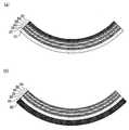
図1(a)及び(b)は本実施形態におけるEL素子100を説明するための断面図であり、(a)はその平面形状を示す図であり、(b)は曲面形状としたときの図である。(First embodiment)
FIGS. 1A and 1B are cross-sectional views for explaining an
図1(a)及び(b)に示すように、EL素子100は、基板10上に、水分の侵入を防止する第1のバリア膜20、第1の電極30、EL発光層40、第2の電極50、第2のバリア膜60が順次積層されて、構成される。 As shown in FIGS. 1A and 1B, the
本実施形態において、上述したような積層構造が形成された基板10の反対側の面にはEL素子100が所望の曲面形状となるように規定する形状支持体70が形成されている。尚、本実施形態においては、図1(b)に示すように、EL素子100を第2のバリア膜60側が凸となるような曲面形状としているため、積層構造が形成された基板10の反対側の面に形状支持体70を設けているが、EL素子100を基板10側が凸となるような曲面形状とする場合には、第2のバリア膜60上に形状支持体70を設ければ良い。 In the present embodiment, a
このように、EL素子100を曲面形状としたときに凸となる面の反対側の面に形状支持体70を設けることにより、EL素子100を湾曲させる際にEL素子100の曲面形状の限界形状以下に制限できるので、EL素子100が過度に湾曲してしまうのを防止することができる。この場合、EL素子100を形成するそれぞれの層の中で最も柔軟性に乏しい層を基準として、その層の破壊曲げ限界を超えないようにEL素子100の曲面形状の限界形状を規定することによって、EL素子100を形成するそれぞれの層が破壊されるのを防止することができる。 In this way, by providing the
ここで破壊曲げ限界とは、第1のバリア膜20または第2のバリア膜60に発生したクラックが、第1の電極30または第2の電極50まで達する直前の状態である。そして、EL素子100において、この破壊曲げ限界の状態が限界形状である。尚、第1のバリア膜20または第2のバリア膜60に発生したクラックが、第1の電極30または第2の電極50まで到達した場合、両電極30、50やEL発光層40が水分や酸素に曝されてしまい、EL素子100の表示品位が著しく低下してしまう。 Here, the fracture bending limit is a state immediately before a crack generated in the
形状支持体70は、所定の角度を有して隣接する一対の斜辺からなるストライプ状の切り欠き部71が表面に複数本並んで設けられる板状部材である。 The
このような切り欠き部71を形成することにより、一対の斜辺が互いに接するところまでEL素子100を曲げることにより所望の曲面形状とすることができ、それ以上EL素子100を曲げることができないことにより曲面形状を限界形状以下に規定することができる。この場合、切り欠き部71を形成する一対の斜辺間の角度を調節することにより、EL素子100の曲面形状の限界形状を調節することができる。またストライプ状の切り欠き部71を複数本設けることにより、EL素子100を湾曲させた際に、その曲面形状を複数箇所で調節することができる。 By forming such a
ここで形状支持体70は、x方向とy方向に辺を有するEL素子100において、所定の角度を有して隣接する一対の斜辺からなる切り欠き部71がx方向及びy方向に沿って設けられていても良い。このように構成することにより、EL素子100をx方向、y方向のどちらの方向から曲げた場合にも曲面形状を限界形状以下に規定することができる。 Here, in the
また形状支持体70は、EL素子100の両面に設けられていても良い。このように構成することにより、EL素子100を基板面に対して垂直な方向軸に沿って上下どちらの方向に凸となるように曲げた場合にも曲面形状を限界形状以下に規定することができる。 Further, the
尚、本実施形態において、形状支持体70は硬度が高い樹脂、例えば、アクリル樹脂を用いて形成される。その他、ポリエーテルスルホン(PES)、ポリエチレンナフタレート(PEN)等を用いても良い。 In the present embodiment, the
次に、本実施形態におけるEL素子100の製造方法について説明する。 Next, a method for manufacturing the
まず、例えばスパッタリング法によって、基板10上にアルミナもしくはAlTiO等からなる第1のバリア膜20を形成する。本実施形態において、基板10は、フレキシブル性を有するプラスチック基板が用いられ、例えば、ポリエーテルスルホン(PES)、ポリエチレンテレフタレート(PET)もしくはポリエチレンナフタレート(PEN)等からなる。 First, the
次に、例えばスパッタリング法を用いて、第1のバリア膜20上に、導電性及び光透過性を有する材料、例えば、インジウムスズ酸化物(ITO)等からなる第1の電極30を形成する。 Next, the
次いで、真空蒸着法によって、第1の電極30上にEL発光層40を形成する。本実施形態において、EL発光層40は、発光層のみからなる単層型であるが、発光層以外のホール注入層、ホール輸送層、電子輸送層、電子注入層等の機能層をも含む多層型であっても良い。EL発光層40は、アルミニウムキノリノール錯体(Alq3)等からなる。Next, the EL
次いで、真空蒸着法によって、EL発光層40上に、光を反射する導電性材料、例えば、アルミニウム等からなる第2の電極50を形成する。 Next, a
最後に、スパッタリング法によって、第2の電極50上にアルミナもしくはAlTiO等からなる第2のバリア膜60を形成する。 Finally, a
このようにして基板10上に、第1のバリア膜20、第1の電極30、EL発光層40、第2の電極50、第2のバリア膜60を順に形成する工程を行う。 In this manner, a step of sequentially forming the
次に、積層構造が形成された基板10の反対側の面に樹脂膜を堆積させ、切り欠き部71の形成領域に開口を有するマスクを形成した後、この樹脂膜の表面を等方性エッチングする。これにより、マスクの開口から等方的に樹脂膜がエッチング除去されるので、一対の斜辺からなる切り欠き部71を樹脂膜に形成することができる。この結果、所定の角度を有して隣接する一対の斜辺からなるストライプ状の切り欠き部71が表面に複数本並んで設けられる板状の形状支持体70を形成することができる。 Next, a resin film is deposited on the opposite surface of the
尚、限定されるものではないが、図3に示すように、第1の電極30と第2の電極50とが直交に交わり、EL発光層40のうち第1の電極30と第2の電極50の交点に位置する部分が発光領域となる所謂マトリックス形状のEL素子の場合は、切り欠き部71の底部、すなわち一対の斜辺(面)の交点(交線)が、EL発光層40の発光領域を通過しないことが望ましい。さらには、第1の電極30または第2の電極50の延設方向と、ストライプの交点(交線)の延設方向とが一致していることが望ましい。 Although not limited, as shown in FIG. 3, the
以下、上記配置が望ましい理由を説明する。マトリックス形状のEL素子の場合、複数の第1の電極30同士が互いに溝31を介して離間して配置されている。そして、この溝31を含め、各第1の電極30の短手方向の端部が絶縁膜32で覆れている。この絶縁膜32は、溝31の中央部に位置する箇所が窪んでおり、その箇所の厚みは第1の電極30の厚みよりも厚い(絶縁膜が1μm程度、電極は0.1〜0.2μm)。また、図示しないが複数の第2の電極50同士も互いに溝を介して離間して配置されている。この複数の第1の電極30と、複数の第2の電極50とは互いに直交して配置されている。そして、EL発光層40と第2の電極50とは、第1の電極30と絶縁膜32の上にも配置される。 Hereinafter, the reason why the above arrangement is desirable will be described. In the case of a matrix-shaped EL element, a plurality of
ここで、発光領域に切り欠き部71の底部が一致すると発光領域内に凸部が発生する。この凸部では光学距離が短くなり、凸部でない部分は表面から見ると斜めとなり光学距離が長くなる。光学距離の違うものを一緒にみると、モアレや干渉縞などの表示不具合となる。このため光学距離による表示不具合を防ぐ為に発光領域外に切り欠き部を形成することが望ましい。また、マトリックス形状のEL素子100を曲げた際の応力を鑑みると、応力の低い無機材料からなる電極部に切り欠き部が来ると電極がクラックして断線し、表示不良に繋がる。 Here, when the bottom of the
また、切り欠き部71を設けて、マトリックス形状のEL素子100を曲げた場合、切り欠き部71の底部(ストライプの交点(交線))には、底部以外よりも大きい応力が発生する可能性がある。EL発光層40の発光領域が存在する箇所は、第1の電極30と第2の電極50とがEL発光層40を挟んで近接しているため、EL素子100を曲げる際に応力が集中すると第1の電極30と第2の電極50とがショートしてしまう可能性もある。 Further, when the notched
このため、切り欠き部71の底部、すなわち一対の斜辺(面)の交点(交線)が、EL発光層40の発光領域を通過しないように配置することが望ましい。すなわち、切り欠き部71の底部を、第1の電極30間の溝31、もしくは、第2の電極50間の溝に配置すれば、上記のような光学距離の差に起因する表示不具合、クラックによる表示不良、第1の電極と第2の電極との間のショートの発生を抑制することができる。
なお、図4に示すような第2の電極50間の溝61に隔壁62を設ける構造の場合は、最も厚みが厚くなる箇所が隔壁62の部分である為、図3とは異なり切り欠き部71の底部がEL発光層40の発光領域を通過するようにすることが望ましい。For this reason, it is desirable to arrange so that the bottom of the
In the case of the structure in which the
(第2実施形態)
次に、第2実施形態について説明する。本実施形態によるEL素子100の製造方法でも、第1実施形態によるEL素子100の製造方法と同様に、基板10上に、第1のバリア膜20、第1の電極30、EL発光層40、第2の電極50、第2のバリア膜60を順に形成する工程を行う。(Second Embodiment)
Next, a second embodiment will be described. In the method for manufacturing the
ただし、本実施形態におけるEL素子100の製造方法では、形状支持体70を形成する工程は、所定の切り欠き部71を有するように形成された金型に樹脂を流し込み、切り欠き部71が形成された樹脂板を成形した後、樹脂板を接着剤によりEL素子100と接着することにより形状支持体70を形成する。このような方法によっても、所定の角度を有して隣接する一対の斜辺からなるストライプ状の切り欠き部71が表面に複数本並んで設けられる板状の形状支持体70を形成することができる。 However, in the method of manufacturing the
(第3実施形態)
次に第3実施形態について説明する。図2(a)は本実施形態におけるEL素子200を説明するための断面図である。(Third embodiment)
Next, a third embodiment will be described. FIG. 2A is a cross-sectional view for explaining the
本実施形態によるEL素子200でも、第1実施形態によるEL素子100と同様に、基板10上に、水分の侵入を防止する第1のバリア膜20、第1の電極30、EL発光層40、第2の電極50、第2のバリア膜60が順次積層されている。 In the
ただし、本実施形態におけるEL素子200では、積層構造が形成された基板10の反対側の面に、基板10が平面形状に戻ろうとする応力とは逆の応力、すなわち基板10をより曲面形状に曲げようとする引張応力を有する形状保持膜80が形成される。 However, in the
形状保持膜80を設けることにより、その形状保持膜の応力により曲面形状を規定することができる。この場合、形状保持膜80の材質を変化させて応力を調整する、または形状保持膜80の厚さを調節することにより、形状保持膜80の全応力が変化するため、EL素子200の曲面形状、例えば曲率を調節することができる。また、このような引張応力を有する膜を形状保持膜80として使用した場合、EL素子200のどちらの面に形状保持膜80を設けた場合にもEL素子200に接する面と反対側の面が凹んだ曲面形状に変形させることが可能となる。 By providing the shape-retaining
一方、図2(b)に示すように形状保持膜が圧縮応力を有する膜90であった場合も、EL素子200のどちらの面に形状保持膜90を設けても、EL素子200を曲面形状にすることができる。なお、この場合は、形状保持膜90がEL素子200に接する面と反対側の面が凸な曲面形状に変形する。 On the other hand, as shown in FIG. 2B, the shape retaining film is a film 90 having a compressive stress, and even if the shape retaining film 90 is provided on either surface of the
次に、図2(a)に示した本実施形態におけるEL素子200の製造方法について説明する。本実施形態によるEL素子200の製造方法でも、第1実施形態によるEL素子100の製造方法と同様に、基板10上に、第1のバリア膜20、第1の電極30、EL発光層40、第2の電極50、第2のバリア膜60を順に形成する工程を行う。 Next, a method for manufacturing the
ただし、本実施形態におけるEL素子200の製造方法では、EL素子200上に、例えばスパッタリング法によって、クロム等からなる引張応力を有した膜80を形成する。この成膜時に発生する応力によりEL素子200を曲面形状に変形させる。これにより、EL素子200に接する面と反対側の面が凹んだ曲面形状に変形しようとする応力を有する形状保持膜80を形成することができる。尚、形状保持膜80を形成する工程として、スパッタ、CVD、蒸着、ALE等の成膜方法を用いても良い。またEL素子200に樹脂膜をコーティングした後、その硬化収縮で所望の応力を得ても良い。 However, in the method for manufacturing the
(変形例)
上記実施形態において、有機ELを対象としたEL素子について説明したが、その際EL素子を構成するそれぞれの層の構成材料は上述したものに限定されるものではない。また、変形例として有機ELの代わりに無機ELを用いることもでき、その際EL素子を構成するEL発光層、電極等のそれぞれの層は公知の材料を用いて構成されていれば良い。(Modification)
In the above-described embodiment, the EL element intended for the organic EL has been described. However, the constituent materials of the respective layers constituting the EL element are not limited to those described above. As a modification, an inorganic EL can be used instead of the organic EL. In this case, each layer such as an EL light-emitting layer and an electrode constituting the EL element may be formed using a known material.
10・・・基板
20・・・第1のバリア膜
30・・・第1の電極
31,61・・・溝
32・・・絶縁膜
40・・・EL発光層
50・・・第2の電極
60・・・第2のバリア膜
62・・・隔壁
70・・・形状支持体
71・・・切り欠き部
80・・・引張応力を有した形状保持膜
90・・・圧縮応力を有した形状保持膜DESCRIPTION OF
Claims (9)
Translated fromJapanese前記EL素子を曲面形状としたときに凸となる面の反対側の面に、前記EL素子が所望の曲面形状となるように規定する形状規定部材を設けることを特徴とするEL素子。In an EL element in which a first barrier film, a first electrode, an EL light emitting layer, a second electrode, and a second barrier film for preventing moisture from entering are sequentially stacked on a substrate,
An EL element comprising a shape defining member for defining the EL element to have a desired curved shape on a surface opposite to a convex surface when the EL element has a curved shape.
前記EL素子を曲面形状としたときに凸となる面の反対側の面に、前記EL素子が所望の曲面形状となるように規定する形状規定部材を形成する工程と、からなることを特徴とするEL素子の製造方法。Forming a first barrier film, a first electrode, an EL light emitting layer, a second electrode, and a second barrier film on a substrate in order;
Forming a shape defining member that defines the EL element to have a desired curved surface shape on a surface opposite to a convex surface when the EL element has a curved surface shape. A method for manufacturing an EL element.
前記形状規定部材を形成する工程は、前記EL素子上に樹脂膜を堆積させた後、この樹脂膜の表面に前記切り欠き部を形成するためのエッチング処理を施すことにより前記形状支持体を形成する工程を有することを特徴とする請求項6記載のEL素子の製造方法。The shape defining member is a plate-like shape support body provided with a plurality of stripe-shaped notches formed of a pair of oblique sides adjacent to each other at a predetermined angle.
In the step of forming the shape defining member, after the resin film is deposited on the EL element, the shape support is formed by performing an etching process for forming the notch on the surface of the resin film. The method of manufacturing an EL element according to claim 6, further comprising: a step of:
前記形状規定部材を形成する工程は、始めに前記切り欠き部を有する樹脂板を成形した後、接着剤で前記EL素子と接着することにより前記形状支持体を形成する工程を有することを特徴とする請求項6記載のEL素子の製造方法。The shape defining member is a plate-like shape support body provided with a plurality of stripe-shaped notches formed of a pair of oblique sides adjacent to each other at a predetermined angle.
The step of forming the shape defining member has a step of forming the shape support by first bonding the EL element with an adhesive after first molding the resin plate having the notch. The manufacturing method of the EL element of Claim 6.
前記形状規定部材を形成する工程は、前記EL素子上に応力を有する膜を成膜する工程を有し、この成膜時に発生する応力により前記EL素子を曲面形状に変形させることを特徴とする請求項6記載のEL素子の製造方法。The shape defining member is a shape-retaining film having a stress that tends to be deformed into a curved shape in which a surface opposite to the surface in contact with the EL element is recessed,
The step of forming the shape defining member includes a step of forming a film having stress on the EL element, and the EL element is deformed into a curved shape by the stress generated during the film formation. The manufacturing method of the EL element of Claim 6.
Priority Applications (1)
| Application Number | Priority Date | Filing Date | Title |
|---|---|---|---|
| JP2008004854AJP2009170173A (en) | 2008-01-11 | 2008-01-11 | El element, and manufacturing method thereof |
Applications Claiming Priority (1)
| Application Number | Priority Date | Filing Date | Title |
|---|---|---|---|
| JP2008004854AJP2009170173A (en) | 2008-01-11 | 2008-01-11 | El element, and manufacturing method thereof |
Publications (1)
| Publication Number | Publication Date |
|---|---|
| JP2009170173Atrue JP2009170173A (en) | 2009-07-30 |
Family
ID=40971133
Family Applications (1)
| Application Number | Title | Priority Date | Filing Date |
|---|---|---|---|
| JP2008004854APendingJP2009170173A (en) | 2008-01-11 | 2008-01-11 | El element, and manufacturing method thereof |
Country Status (1)
| Country | Link |
|---|---|
| JP (1) | JP2009170173A (en) |
Cited By (71)
| Publication number | Priority date | Publication date | Assignee | Title |
|---|---|---|---|---|
| JP2014016616A (en)* | 2012-07-10 | 2014-01-30 | Samsung Display Co Ltd | Flexible display device |
| JP2014056815A (en)* | 2012-08-10 | 2014-03-27 | Semiconductor Energy Lab Co Ltd | Light-emitting device manufacturing method |
| WO2014065169A1 (en)* | 2012-10-24 | 2014-05-01 | コニカミノルタ株式会社 | Light-emitting apparatus and method for manufacturing same |
| WO2014136259A1 (en)* | 2013-03-08 | 2014-09-12 | パイオニア株式会社 | Light-emitting element |
| WO2014137113A1 (en)* | 2013-03-04 | 2014-09-12 | 주식회사 엘엠에스 | Flexible display device |
| WO2014206647A1 (en)* | 2013-06-28 | 2014-12-31 | Osram Oled Gmbh | Optoelectronic component and method for producing an optoelectronic component |
| JP2015046264A (en)* | 2013-08-27 | 2015-03-12 | パイオニア株式会社 | Light-emitting device and method of manufacturing light-emitting device |
| JP2015046263A (en)* | 2013-08-27 | 2015-03-12 | パイオニア株式会社 | Light emitting device |
| EP2806475A3 (en)* | 2013-05-21 | 2015-03-25 | Samsung Display Co., Ltd. | Organic light emitting diode display and method of manufacturing the same |
| KR20150044080A (en)* | 2013-10-15 | 2015-04-24 | 삼성디스플레이 주식회사 | Organic light emitting device and manufacturing method thereof |
| KR20150050706A (en)* | 2013-10-30 | 2015-05-11 | 삼성디스플레이 주식회사 | Display device |
| CN104701342A (en)* | 2013-12-05 | 2015-06-10 | 乐金显示有限公司 | Curved display device |
| CN104701463A (en)* | 2013-12-06 | 2015-06-10 | 双叶电子工业株式会社 | Organic electroluminescence device |
| CN104752622A (en)* | 2013-12-31 | 2015-07-01 | 昆山国显光电有限公司 | Flexible organic lighting display device |
| WO2015127458A1 (en)* | 2014-02-24 | 2015-08-27 | Mc10, Inc. | Conformal electronics with deformation indicators |
| WO2015163272A1 (en)* | 2014-04-24 | 2015-10-29 | シャープ株式会社 | Display device |
| WO2015170213A1 (en)* | 2014-05-06 | 2015-11-12 | Semiconductor Energy Laboratory Co., Ltd. | Electronic device |
| CN105096752A (en)* | 2015-08-25 | 2015-11-25 | 京东方科技集团股份有限公司 | Flexible display panel and display device |
| US9295842B2 (en) | 2012-07-05 | 2016-03-29 | Mc10, Inc. | Catheter or guidewire device including flow sensing and use thereof |
| JP2016058292A (en)* | 2014-09-11 | 2016-04-21 | パナソニックIpマネジメント株式会社 | Light emission device and luminaire using the same |
| WO2016090527A1 (en)* | 2014-12-08 | 2016-06-16 | 深圳市柔宇科技有限公司 | Flexible screen protection structure and manufacturing method therefor, and flexible display screen applying flexible screen protection structure |
| US9372123B2 (en) | 2013-08-05 | 2016-06-21 | Mc10, Inc. | Flexible temperature sensor including conformable electronics |
| US9408305B2 (en) | 2012-06-11 | 2016-08-02 | Mc10, Inc. | Strain isolation structures for stretchable electronics |
| WO2016123984A1 (en) | 2015-02-05 | 2016-08-11 | Boe Technology Group Co., Ltd. | Cover plate, and curved display apparatus |
| US9516758B2 (en) | 2008-10-07 | 2016-12-06 | Mc10, Inc. | Extremely stretchable electronics |
| US9554850B2 (en) | 2012-07-05 | 2017-01-31 | Mc10, Inc. | Catheter device including flow sensing |
| JP2017504069A (en)* | 2013-12-24 | 2017-02-02 | ポリエラ コーポレイション | Support structure for an attachable two-dimensional flexible electronic device |
| US9583428B2 (en) | 2012-10-09 | 2017-02-28 | Mc10, Inc. | Embedding thin chips in polymer |
| USD781270S1 (en) | 2014-10-15 | 2017-03-14 | Mc10, Inc. | Electronic device having antenna |
| US9622680B2 (en) | 2011-08-05 | 2017-04-18 | Mc10, Inc. | Catheter balloon methods and apparatus employing sensing elements |
| US9662069B2 (en) | 2008-10-07 | 2017-05-30 | Mc10, Inc. | Systems, methods, and devices having stretchable integrated circuitry for sensing and delivering therapy |
| WO2017100999A1 (en)* | 2015-12-15 | 2017-06-22 | 深圳市柔宇科技有限公司 | Flexible display screen and terminal device |
| US9704908B2 (en) | 2008-10-07 | 2017-07-11 | Mc10, Inc. | Methods and applications of non-planar imaging arrays |
| US9723122B2 (en) | 2009-10-01 | 2017-08-01 | Mc10, Inc. | Protective cases with integrated electronics |
| US9723711B2 (en) | 2011-05-27 | 2017-08-01 | Mc10, Inc. | Method for fabricating a flexible electronic structure and a flexible electronic structure |
| JP2017139234A (en)* | 2017-04-07 | 2017-08-10 | パイオニア株式会社 | Light-emitting element |
| US9757050B2 (en) | 2011-08-05 | 2017-09-12 | Mc10, Inc. | Catheter balloon employing force sensing elements |
| JP2017191784A (en)* | 2017-06-20 | 2017-10-19 | パイオニア株式会社 | Light emitting device |
| US9833190B2 (en) | 2008-10-07 | 2017-12-05 | Mc10, Inc. | Methods of detecting parameters of a lumen |
| US9846829B2 (en) | 2012-10-09 | 2017-12-19 | Mc10, Inc. | Conformal electronics integrated with apparel |
| US9899330B2 (en) | 2014-10-03 | 2018-02-20 | Mc10, Inc. | Flexible electronic circuits with embedded integrated circuit die |
| US9949691B2 (en) | 2013-11-22 | 2018-04-24 | Mc10, Inc. | Conformal sensor systems for sensing and analysis of cardiac activity |
| KR101876540B1 (en)* | 2011-12-28 | 2018-07-10 | 삼성디스플레이 주식회사 | Flexible display apparatus and the method of manufacturing the same |
| JP2018206783A (en)* | 2018-10-03 | 2018-12-27 | パイオニア株式会社 | Light-emitting element |
| US10277386B2 (en) | 2016-02-22 | 2019-04-30 | Mc10, Inc. | System, devices, and method for on-body data and power transmission |
| US10297572B2 (en) | 2014-10-06 | 2019-05-21 | Mc10, Inc. | Discrete flexible interconnects for modules of integrated circuits |
| US10300371B2 (en) | 2015-10-01 | 2019-05-28 | Mc10, Inc. | Method and system for interacting with a virtual environment |
| CN109845400A (en)* | 2016-10-13 | 2019-06-04 | 夏普株式会社 | The manufacturing method of organic EL display device and organic EL display device |
| US10334724B2 (en) | 2013-05-14 | 2019-06-25 | Mc10, Inc. | Conformal electronics including nested serpentine interconnects |
| US10372164B2 (en) | 2013-12-24 | 2019-08-06 | Flexterra, Inc. | Flexible electronic display with user interface based on sensed movements |
| US10398343B2 (en) | 2015-03-02 | 2019-09-03 | Mc10, Inc. | Perspiration sensor |
| WO2019167174A1 (en)* | 2018-02-28 | 2019-09-06 | シャープ株式会社 | Display device |
| US10410962B2 (en) | 2014-01-06 | 2019-09-10 | Mc10, Inc. | Encapsulated conformal electronic systems and devices, and methods of making and using the same |
| US10447347B2 (en) | 2016-08-12 | 2019-10-15 | Mc10, Inc. | Wireless charger and high speed data off-loader |
| US10467926B2 (en) | 2013-10-07 | 2019-11-05 | Mc10, Inc. | Conformal sensor systems for sensing and analysis |
| US10477354B2 (en) | 2015-02-20 | 2019-11-12 | Mc10, Inc. | Automated detection and configuration of wearable devices based on on-body status, location, and/or orientation |
| US10485118B2 (en) | 2014-03-04 | 2019-11-19 | Mc10, Inc. | Multi-part flexible encapsulation housing for electronic devices and methods of making the same |
| KR102057612B1 (en)* | 2013-05-21 | 2019-12-20 | 삼성디스플레이 주식회사 | Organic light emitting device and manufacturing method thereof |
| KR20190141630A (en)* | 2019-12-13 | 2019-12-24 | 삼성디스플레이 주식회사 | Organic light emitting device and manufacturing method thereof |
| US10532211B2 (en) | 2015-10-05 | 2020-01-14 | Mc10, Inc. | Method and system for neuromodulation and stimulation |
| US10621956B2 (en) | 2014-02-10 | 2020-04-14 | Flexterra, Inc. | Attachable device with flexible electronic display orientation detection |
| US10653332B2 (en) | 2015-07-17 | 2020-05-19 | Mc10, Inc. | Conductive stiffener, method of making a conductive stiffener, and conductive adhesive and encapsulation layers |
| US10673280B2 (en) | 2016-02-22 | 2020-06-02 | Mc10, Inc. | System, device, and method for coupled hub and sensor node on-body acquisition of sensor information |
| US10709384B2 (en) | 2015-08-19 | 2020-07-14 | Mc10, Inc. | Wearable heat flux devices and methods of use |
| JP2020145200A (en)* | 2015-02-27 | 2020-09-10 | 株式会社半導体エネルギー研究所 | Power storage device |
| US10782734B2 (en) | 2015-02-26 | 2020-09-22 | Flexterra, Inc. | Attachable device having a flexible electronic component |
| US10834822B2 (en) | 2013-12-24 | 2020-11-10 | Flexterra, Inc. | Support structures for a flexible electronic component |
| US11079620B2 (en) | 2013-08-13 | 2021-08-03 | Flexterra, Inc. | Optimization of electronic display areas |
| US11145838B2 (en) | 2013-05-21 | 2021-10-12 | Samsung Display Co., Ltd. | Organic light emitting diode display and method of manufacturing the same |
| US11154235B2 (en) | 2016-04-19 | 2021-10-26 | Medidata Solutions, Inc. | Method and system for measuring perspiration |
| US11453193B2 (en)* | 2017-07-17 | 2022-09-27 | 3M Innovative Properties Company | Curvature limiting film |
Citations (4)
| Publication number | Priority date | Publication date | Assignee | Title |
|---|---|---|---|---|
| JP2003019745A (en)* | 2001-07-10 | 2003-01-21 | Pioneer Electronic Corp | Planar member and method for forming the same |
| JP2005212230A (en)* | 2004-01-29 | 2005-08-11 | Tomoegawa Paper Co Ltd | Transparent gas barrier film and electroluminescence device |
| JP2006507528A (en)* | 2002-11-22 | 2006-03-02 | コーニンクレッカ フィリップス エレクトロニクス エヌ ヴィ | Method for manufacturing curved display |
| WO2006090434A1 (en)* | 2005-02-22 | 2006-08-31 | Fujifilm Corporation | Flexible substrate supprerssed from being plastically deformed, and flexible image display device |
- 2008
- 2008-01-11JPJP2008004854Apatent/JP2009170173A/enactivePending
Patent Citations (4)
| Publication number | Priority date | Publication date | Assignee | Title |
|---|---|---|---|---|
| JP2003019745A (en)* | 2001-07-10 | 2003-01-21 | Pioneer Electronic Corp | Planar member and method for forming the same |
| JP2006507528A (en)* | 2002-11-22 | 2006-03-02 | コーニンクレッカ フィリップス エレクトロニクス エヌ ヴィ | Method for manufacturing curved display |
| JP2005212230A (en)* | 2004-01-29 | 2005-08-11 | Tomoegawa Paper Co Ltd | Transparent gas barrier film and electroluminescence device |
| WO2006090434A1 (en)* | 2005-02-22 | 2006-08-31 | Fujifilm Corporation | Flexible substrate supprerssed from being plastically deformed, and flexible image display device |
Cited By (153)
| Publication number | Priority date | Publication date | Assignee | Title |
|---|---|---|---|---|
| US9516758B2 (en) | 2008-10-07 | 2016-12-06 | Mc10, Inc. | Extremely stretchable electronics |
| US9894757B2 (en) | 2008-10-07 | 2018-02-13 | Mc10, Inc. | Extremely stretchable electronics |
| US9704908B2 (en) | 2008-10-07 | 2017-07-11 | Mc10, Inc. | Methods and applications of non-planar imaging arrays |
| US9662069B2 (en) | 2008-10-07 | 2017-05-30 | Mc10, Inc. | Systems, methods, and devices having stretchable integrated circuitry for sensing and delivering therapy |
| US10186546B2 (en) | 2008-10-07 | 2019-01-22 | Mc10, Inc. | Systems, methods, and devices having stretchable integrated circuitry for sensing and delivering therapy |
| US9833190B2 (en) | 2008-10-07 | 2017-12-05 | Mc10, Inc. | Methods of detecting parameters of a lumen |
| US10325951B2 (en) | 2008-10-07 | 2019-06-18 | Mc10, Inc. | Methods and applications of non-planar imaging arrays |
| US10383219B2 (en) | 2008-10-07 | 2019-08-13 | Mc10, Inc. | Extremely stretchable electronics |
| US9723122B2 (en) | 2009-10-01 | 2017-08-01 | Mc10, Inc. | Protective cases with integrated electronics |
| US9723711B2 (en) | 2011-05-27 | 2017-08-01 | Mc10, Inc. | Method for fabricating a flexible electronic structure and a flexible electronic structure |
| US9757050B2 (en) | 2011-08-05 | 2017-09-12 | Mc10, Inc. | Catheter balloon employing force sensing elements |
| US9622680B2 (en) | 2011-08-05 | 2017-04-18 | Mc10, Inc. | Catheter balloon methods and apparatus employing sensing elements |
| US12242305B2 (en) | 2011-12-28 | 2025-03-04 | Samsung Display Co., Ltd. | Flexible display apparatus and method of manufacturing the same |
| US10978670B2 (en) | 2011-12-28 | 2021-04-13 | Samsung Display Co., Ltd. | Flexible display apparatus and method of manufacturing the same |
| US11467632B2 (en) | 2011-12-28 | 2022-10-11 | Samsung Display Co., Ltd. | Flexible display apparatus and method of manufacturing the same |
| US11815960B2 (en) | 2011-12-28 | 2023-11-14 | Samsung Display Co., Ltd. | Flexible display apparatus and method of manufacturing the same |
| US10128460B2 (en) | 2011-12-28 | 2018-11-13 | Samsung Display Co., Ltd. | Flexible display apparatus and method of manufacturing the same |
| KR101876540B1 (en)* | 2011-12-28 | 2018-07-10 | 삼성디스플레이 주식회사 | Flexible display apparatus and the method of manufacturing the same |
| US9408305B2 (en) | 2012-06-11 | 2016-08-02 | Mc10, Inc. | Strain isolation structures for stretchable electronics |
| US9844145B2 (en) | 2012-06-11 | 2017-12-12 | Mc10, Inc. | Strain isolation structures for stretchable electronics |
| US9801557B2 (en) | 2012-07-05 | 2017-10-31 | Mc10, Inc. | Catheter or guidewire device including flow sensing and use thereof |
| US9750421B2 (en) | 2012-07-05 | 2017-09-05 | Mc10, Inc. | Catheter or guidewire device including flow sensing and use thereof |
| US9554850B2 (en) | 2012-07-05 | 2017-01-31 | Mc10, Inc. | Catheter device including flow sensing |
| US9295842B2 (en) | 2012-07-05 | 2016-03-29 | Mc10, Inc. | Catheter or guidewire device including flow sensing and use thereof |
| KR101903053B1 (en) | 2012-07-10 | 2018-11-23 | 삼성디스플레이 주식회사 | Flexible display device |
| JP2014016616A (en)* | 2012-07-10 | 2014-01-30 | Samsung Display Co Ltd | Flexible display device |
| KR102133158B1 (en)* | 2012-08-10 | 2020-07-14 | 가부시키가이샤 한도오따이 에네루기 켄큐쇼 | Method for manufacturing light-emitting device |
| JP2014056815A (en)* | 2012-08-10 | 2014-03-27 | Semiconductor Energy Lab Co Ltd | Light-emitting device manufacturing method |
| US11557745B2 (en) | 2012-08-10 | 2023-01-17 | Semiconductor Energy Laboratory Co., Ltd. | Method for manufacturing light-emitting device |
| KR20150040982A (en)* | 2012-08-10 | 2015-04-15 | 가부시키가이샤 한도오따이 에네루기 켄큐쇼 | Method for manufacturing light-emitting device |
| US10326100B2 (en) | 2012-08-10 | 2019-06-18 | Semiconductor Energy Laboratory Co., Ltd. | Method for manufacturing light-emitting device |
| US10862065B2 (en) | 2012-08-10 | 2020-12-08 | Semiconductor Energy Laboratory Co., Ltd. | Method for manufacturing light-emitting device |
| US10296819B2 (en) | 2012-10-09 | 2019-05-21 | Mc10, Inc. | Conformal electronics integrated with apparel |
| US9846829B2 (en) | 2012-10-09 | 2017-12-19 | Mc10, Inc. | Conformal electronics integrated with apparel |
| US9583428B2 (en) | 2012-10-09 | 2017-02-28 | Mc10, Inc. | Embedding thin chips in polymer |
| US10032709B2 (en) | 2012-10-09 | 2018-07-24 | Mc10, Inc. | Embedding thin chips in polymer |
| JPWO2014065169A1 (en)* | 2012-10-24 | 2016-09-08 | コニカミノルタ株式会社 | Light emitting device and manufacturing method thereof |
| US9755166B2 (en) | 2012-10-24 | 2017-09-05 | Konica Minolta, Inc. | Luminescent device and method of manufacturing the same including forming a plurality of notches or slits in a substrate to enable planar light emittance in a curved state |
| WO2014065169A1 (en)* | 2012-10-24 | 2014-05-01 | コニカミノルタ株式会社 | Light-emitting apparatus and method for manufacturing same |
| US10506707B2 (en) | 2013-03-04 | 2019-12-10 | Lms Co., Ltd | Flexible display device |
| US20160014883A1 (en)* | 2013-03-04 | 2016-01-14 | Lms Co., Ltd. | Flexible display device |
| KR101447885B1 (en) | 2013-03-04 | 2014-10-08 | 주식회사 엘엠에스 | flexible display device |
| WO2014137113A1 (en)* | 2013-03-04 | 2014-09-12 | 주식회사 엘엠에스 | Flexible display device |
| KR20180129992A (en)* | 2013-03-08 | 2018-12-05 | 파이오니아 가부시키가이샤 | Light-emitting element |
| KR102139898B1 (en)* | 2013-03-08 | 2020-07-30 | 파이오니아 가부시키가이샤 | Light-emitting element |
| KR101924772B1 (en)* | 2013-03-08 | 2018-12-04 | 파이오니아 가부시키가이샤 | Light-emitting element |
| WO2014136259A1 (en)* | 2013-03-08 | 2014-09-12 | パイオニア株式会社 | Light-emitting element |
| US12120942B2 (en) | 2013-03-08 | 2024-10-15 | Pioneer Corporation | Light emitting element including a fixation member fixing a flexible plate-like portion |
| US10374176B2 (en) | 2013-03-08 | 2019-08-06 | Pioneer Corporation | Flexible organic electro-luminescence element |
| JPWO2014136259A1 (en)* | 2013-03-08 | 2017-02-09 | パイオニア株式会社 | Light emitting element |
| KR20190120451A (en)* | 2013-03-08 | 2019-10-23 | 파이오니아 가부시키가이샤 | Light-emitting element |
| EP2966937A4 (en)* | 2013-03-08 | 2016-10-26 | Pioneer Corp | Light-emitting element |
| US11637253B2 (en) | 2013-03-08 | 2023-04-25 | Pioneer Corporation | Light emitting element including flexible plate-like portion and fixation member fixing flexible plate-like portion |
| CN108511615A (en)* | 2013-03-08 | 2018-09-07 | 日本先锋公司 | Light-emitting component |
| KR102045171B1 (en)* | 2013-03-08 | 2019-11-14 | 파이오니아 가부시키가이샤 | Light-emitting element |
| CN105009689B (en)* | 2013-03-08 | 2018-06-22 | 日本先锋公司 | Light emitting element |
| CN108511615B (en)* | 2013-03-08 | 2020-03-03 | 日本先锋公司 | light-emitting element |
| US10665795B2 (en) | 2013-03-08 | 2020-05-26 | Pioneer Corporation | Top emission type light emitting element |
| CN105009689A (en)* | 2013-03-08 | 2015-10-28 | 日本先锋公司 | Light emitting element |
| US10937977B2 (en) | 2013-03-08 | 2021-03-02 | Pioneer Corporation | Top emission type light emitting element |
| US10334724B2 (en) | 2013-05-14 | 2019-06-25 | Mc10, Inc. | Conformal electronics including nested serpentine interconnects |
| CN109256412B (en)* | 2013-05-21 | 2023-08-08 | 三星显示有限公司 | Organic light emitting diode display and manufacturing method thereof |
| CN109256412A (en)* | 2013-05-21 | 2019-01-22 | 三星显示有限公司 | Organic light emitting diode display and its manufacturing method |
| US11145838B2 (en) | 2013-05-21 | 2021-10-12 | Samsung Display Co., Ltd. | Organic light emitting diode display and method of manufacturing the same |
| KR102057612B1 (en)* | 2013-05-21 | 2019-12-20 | 삼성디스플레이 주식회사 | Organic light emitting device and manufacturing method thereof |
| US9614167B2 (en) | 2013-05-21 | 2017-04-04 | Samsung Display Co., Ltd. | Organic light emitting diode display and method of manufacturing the same |
| EP2806475A3 (en)* | 2013-05-21 | 2015-03-25 | Samsung Display Co., Ltd. | Organic light emitting diode display and method of manufacturing the same |
| US9203050B2 (en) | 2013-05-21 | 2015-12-01 | Samsung Display Co., Ltd. | Organic light emitting diode display and method of manufacturing the same |
| US10038161B2 (en) | 2013-05-21 | 2018-07-31 | Samsung Display Co., Ltd. | Organic light emitting diode display and method of manufacturing the same |
| WO2014206647A1 (en)* | 2013-06-28 | 2014-12-31 | Osram Oled Gmbh | Optoelectronic component and method for producing an optoelectronic component |
| US9372123B2 (en) | 2013-08-05 | 2016-06-21 | Mc10, Inc. | Flexible temperature sensor including conformable electronics |
| US10482743B2 (en) | 2013-08-05 | 2019-11-19 | Mc10, Inc. | Flexible temperature sensor including conformable electronics |
| US11079620B2 (en) | 2013-08-13 | 2021-08-03 | Flexterra, Inc. | Optimization of electronic display areas |
| JP2015046264A (en)* | 2013-08-27 | 2015-03-12 | パイオニア株式会社 | Light-emitting device and method of manufacturing light-emitting device |
| JP2015046263A (en)* | 2013-08-27 | 2015-03-12 | パイオニア株式会社 | Light emitting device |
| US10467926B2 (en) | 2013-10-07 | 2019-11-05 | Mc10, Inc. | Conformal sensor systems for sensing and analysis |
| KR102183086B1 (en)* | 2013-10-15 | 2020-11-26 | 삼성디스플레이 주식회사 | Organic light emitting device and manufacturing method thereof |
| KR20150044080A (en)* | 2013-10-15 | 2015-04-24 | 삼성디스플레이 주식회사 | Organic light emitting device and manufacturing method thereof |
| KR20150050706A (en)* | 2013-10-30 | 2015-05-11 | 삼성디스플레이 주식회사 | Display device |
| KR102111726B1 (en) | 2013-10-30 | 2020-05-18 | 삼성디스플레이 주식회사 | Display device |
| US10258282B2 (en) | 2013-11-22 | 2019-04-16 | Mc10, Inc. | Conformal sensor systems for sensing and analysis of cardiac activity |
| US9949691B2 (en) | 2013-11-22 | 2018-04-24 | Mc10, Inc. | Conformal sensor systems for sensing and analysis of cardiac activity |
| US10381427B2 (en) | 2013-12-05 | 2019-08-13 | Lg Display Co., Ltd. | Curved display device |
| US9978825B2 (en) | 2013-12-05 | 2018-05-22 | Lg Display Co., Ltd. | Curved display device |
| CN104701342A (en)* | 2013-12-05 | 2015-06-10 | 乐金显示有限公司 | Curved display device |
| CN104701463A (en)* | 2013-12-06 | 2015-06-10 | 双叶电子工业株式会社 | Organic electroluminescence device |
| EP2884554A1 (en)* | 2013-12-06 | 2015-06-17 | Futaba Corporation | Organic electroluminescence device |
| CN104701463B (en)* | 2013-12-06 | 2018-01-16 | 双叶电子工业株式会社 | Organic electroluminescent apparatus |
| US10372164B2 (en) | 2013-12-24 | 2019-08-06 | Flexterra, Inc. | Flexible electronic display with user interface based on sensed movements |
| JP2017504069A (en)* | 2013-12-24 | 2017-02-02 | ポリエラ コーポレイション | Support structure for an attachable two-dimensional flexible electronic device |
| US10834822B2 (en) | 2013-12-24 | 2020-11-10 | Flexterra, Inc. | Support structures for a flexible electronic component |
| CN104752622A (en)* | 2013-12-31 | 2015-07-01 | 昆山国显光电有限公司 | Flexible organic lighting display device |
| CN104752622B (en)* | 2013-12-31 | 2017-10-10 | 昆山国显光电有限公司 | A kind of flexible organic light-emitting display device |
| US10410962B2 (en) | 2014-01-06 | 2019-09-10 | Mc10, Inc. | Encapsulated conformal electronic systems and devices, and methods of making and using the same |
| US10621956B2 (en) | 2014-02-10 | 2020-04-14 | Flexterra, Inc. | Attachable device with flexible electronic display orientation detection |
| WO2015127458A1 (en)* | 2014-02-24 | 2015-08-27 | Mc10, Inc. | Conformal electronics with deformation indicators |
| US10485118B2 (en) | 2014-03-04 | 2019-11-19 | Mc10, Inc. | Multi-part flexible encapsulation housing for electronic devices and methods of making the same |
| WO2015163272A1 (en)* | 2014-04-24 | 2015-10-29 | シャープ株式会社 | Display device |
| WO2015170213A1 (en)* | 2014-05-06 | 2015-11-12 | Semiconductor Energy Laboratory Co., Ltd. | Electronic device |
| US9891725B2 (en) | 2014-05-06 | 2018-02-13 | Semiconductor Energy Laboratory Co., Ltd. | Electronic device |
| JP2015228022A (en)* | 2014-05-06 | 2015-12-17 | 株式会社半導体エネルギー研究所 | Electronic device |
| JP7668327B2 (en) | 2014-05-06 | 2025-04-24 | 株式会社半導体エネルギー研究所 | Electronics |
| US10101826B2 (en) | 2014-05-06 | 2018-10-16 | Semiconductor Energy Laboratory Co., Ltd. | Electronic device |
| US11740728B2 (en) | 2014-05-06 | 2023-08-29 | Semiconductor Energy Laboratory Co., Ltd. | Electronic device |
| JP7400048B2 (en) | 2014-05-06 | 2023-12-18 | 株式会社半導体エネルギー研究所 | Electronics |
| JP2024019344A (en)* | 2014-05-06 | 2024-02-08 | 株式会社半導体エネルギー研究所 | electronic equipment |
| CN116092384A (en)* | 2014-05-06 | 2023-05-09 | 株式会社半导体能源研究所 | Electronic equipment |
| CN106463079A (en)* | 2014-05-06 | 2017-02-22 | 株式会社半导体能源研究所 | Electronic device |
| CN106463079B (en)* | 2014-05-06 | 2019-05-14 | 株式会社半导体能源研究所 | Electronic equipment |
| US10606379B2 (en) | 2014-05-06 | 2020-03-31 | Semiconductor Energy Laboratory Co., Ltd. | Electronic device |
| US12197671B2 (en) | 2014-05-06 | 2025-01-14 | Semiconductor Energy Laboratory Co., Ltd. | Electronic device |
| US9337434B2 (en) | 2014-05-06 | 2016-05-10 | Semiconductor Energy Laboratory Co., Ltd. | Electronic device |
| JP2022188181A (en)* | 2014-05-06 | 2022-12-20 | 株式会社半導体エネルギー研究所 | Electronics |
| US11216106B2 (en) | 2014-05-06 | 2022-01-04 | Semiconductor Energy Laboratory Co., Ltd. | Electronic device |
| JP2016058292A (en)* | 2014-09-11 | 2016-04-21 | パナソニックIpマネジメント株式会社 | Light emission device and luminaire using the same |
| US9899330B2 (en) | 2014-10-03 | 2018-02-20 | Mc10, Inc. | Flexible electronic circuits with embedded integrated circuit die |
| US10297572B2 (en) | 2014-10-06 | 2019-05-21 | Mc10, Inc. | Discrete flexible interconnects for modules of integrated circuits |
| USD781270S1 (en) | 2014-10-15 | 2017-03-14 | Mc10, Inc. | Electronic device having antenna |
| USD825537S1 (en) | 2014-10-15 | 2018-08-14 | Mc10, Inc. | Electronic device having antenna |
| WO2016090527A1 (en)* | 2014-12-08 | 2016-06-16 | 深圳市柔宇科技有限公司 | Flexible screen protection structure and manufacturing method therefor, and flexible display screen applying flexible screen protection structure |
| US10810910B2 (en) | 2014-12-08 | 2020-10-20 | Shenzhen Royole Technologies Co. Ltd. | Flexible screen protection structure and method for manufacturing the same, and flexible display screen using the same |
| JP2018503860A (en)* | 2014-12-08 | 2018-02-08 | シェンジェン ロイオル テクノロジーズ カンパニー リミテッドShenzhen Royole Technologies Co., Ltd. | FLEXIBLE SCREEN PROTECTION STRUCTURE AND MANUFACTURING METHOD THEREOF |
| EP3254318B1 (en)* | 2015-02-05 | 2020-11-04 | Boe Technology Group Co. Ltd. | Cover plate, and curved display apparatus |
| WO2016123984A1 (en) | 2015-02-05 | 2016-08-11 | Boe Technology Group Co., Ltd. | Cover plate, and curved display apparatus |
| US10477354B2 (en) | 2015-02-20 | 2019-11-12 | Mc10, Inc. | Automated detection and configuration of wearable devices based on on-body status, location, and/or orientation |
| US10986465B2 (en) | 2015-02-20 | 2021-04-20 | Medidata Solutions, Inc. | Automated detection and configuration of wearable devices based on on-body status, location, and/or orientation |
| US10782734B2 (en) | 2015-02-26 | 2020-09-22 | Flexterra, Inc. | Attachable device having a flexible electronic component |
| JP6990270B2 (en) | 2015-02-27 | 2022-01-12 | 株式会社半導体エネルギー研究所 | Power storage device |
| US12406816B2 (en) | 2015-02-27 | 2025-09-02 | Semiconductor Energy Laboratory Co., Ltd. | Power storage device, light-emitting device, and electronic device |
| JP2020145200A (en)* | 2015-02-27 | 2020-09-10 | 株式会社半導体エネルギー研究所 | Power storage device |
| US11869715B2 (en) | 2015-02-27 | 2024-01-09 | Semiconductor Energy Laboratory Co., Ltd. | Power storage device, light-emitting device, and electronic device |
| US10398343B2 (en) | 2015-03-02 | 2019-09-03 | Mc10, Inc. | Perspiration sensor |
| US10653332B2 (en) | 2015-07-17 | 2020-05-19 | Mc10, Inc. | Conductive stiffener, method of making a conductive stiffener, and conductive adhesive and encapsulation layers |
| US10709384B2 (en) | 2015-08-19 | 2020-07-14 | Mc10, Inc. | Wearable heat flux devices and methods of use |
| CN105096752A (en)* | 2015-08-25 | 2015-11-25 | 京东方科技集团股份有限公司 | Flexible display panel and display device |
| US10300371B2 (en) | 2015-10-01 | 2019-05-28 | Mc10, Inc. | Method and system for interacting with a virtual environment |
| US10532211B2 (en) | 2015-10-05 | 2020-01-14 | Mc10, Inc. | Method and system for neuromodulation and stimulation |
| WO2017100999A1 (en)* | 2015-12-15 | 2017-06-22 | 深圳市柔宇科技有限公司 | Flexible display screen and terminal device |
| US10567152B2 (en) | 2016-02-22 | 2020-02-18 | Mc10, Inc. | System, devices, and method for on-body data and power transmission |
| US10277386B2 (en) | 2016-02-22 | 2019-04-30 | Mc10, Inc. | System, devices, and method for on-body data and power transmission |
| US10673280B2 (en) | 2016-02-22 | 2020-06-02 | Mc10, Inc. | System, device, and method for coupled hub and sensor node on-body acquisition of sensor information |
| US11154235B2 (en) | 2016-04-19 | 2021-10-26 | Medidata Solutions, Inc. | Method and system for measuring perspiration |
| US11992326B2 (en) | 2016-04-19 | 2024-05-28 | Medidata Solutions, Inc. | Method and system for measuring perspiration |
| US10447347B2 (en) | 2016-08-12 | 2019-10-15 | Mc10, Inc. | Wireless charger and high speed data off-loader |
| CN109845400B (en)* | 2016-10-13 | 2021-10-22 | 夏普株式会社 | Organic EL display device and manufacturing method of organic EL display device |
| CN109845400A (en)* | 2016-10-13 | 2019-06-04 | 夏普株式会社 | The manufacturing method of organic EL display device and organic EL display device |
| JP2017139234A (en)* | 2017-04-07 | 2017-08-10 | パイオニア株式会社 | Light-emitting element |
| JP2017191784A (en)* | 2017-06-20 | 2017-10-19 | パイオニア株式会社 | Light emitting device |
| US11453193B2 (en)* | 2017-07-17 | 2022-09-27 | 3M Innovative Properties Company | Curvature limiting film |
| WO2019167174A1 (en)* | 2018-02-28 | 2019-09-06 | シャープ株式会社 | Display device |
| JP2018206783A (en)* | 2018-10-03 | 2018-12-27 | パイオニア株式会社 | Light-emitting element |
| KR20190141630A (en)* | 2019-12-13 | 2019-12-24 | 삼성디스플레이 주식회사 | Organic light emitting device and manufacturing method thereof |
| KR102158803B1 (en)* | 2019-12-13 | 2020-09-23 | 삼성디스플레이 주식회사 | Organic light emitting device and manufacturing method thereof |
Similar Documents
| Publication | Publication Date | Title |
|---|---|---|
| JP2009170173A (en) | El element, and manufacturing method thereof | |
| KR101882159B1 (en) | Display device with micro cover layer and manufacturing method for the same | |
| US7671959B2 (en) | Display device and manufacturing method thereof | |
| KR102530485B1 (en) | Display device having divided wiring pattern | |
| KR101864563B1 (en) | Flexible display device with wire having reinforced portion and manufacturing method for the same | |
| CN105009689B (en) | Light emitting element | |
| CN109256481B (en) | Display panel and display device | |
| US20200396837A1 (en) | Flexible base substrate, manufacturing method thereof, display device | |
| US11937449B2 (en) | Sealing structure and light emitting device | |
| CN109461826B (en) | Display panel and display device | |
| CN109148538A (en) | The manufacturing method of display base plate, display device and display base plate | |
| CN114583080B (en) | Flexible display panel and method for preparing the same | |
| US11899889B2 (en) | Touch display panel and electronic device | |
| US20170279073A1 (en) | Display device | |
| CN105389035A (en) | Display apparatus | |
| JP2010086704A (en) | Organic electroluminescent panel | |
| US20060087226A1 (en) | Organic LED vapor deposition mask | |
| JP6208250B2 (en) | Light emitting device | |
| JP7232876B2 (en) | light emitting device | |
| JP2016119201A (en) | Light-emitting device | |
| JP2006221892A (en) | Display device | |
| CN108336098B (en) | Anti-static electrode structure and display panel | |
| WO2016157321A1 (en) | Light emitting device | |
| JP2007066709A (en) | Electroluminescent device | |
| JP2008010268A (en) | Method of manufacturing metal mask and organic electroluminescent display |
Legal Events
| Date | Code | Title | Description |
|---|---|---|---|
| A621 | Written request for application examination | Free format text:JAPANESE INTERMEDIATE CODE: A621 Effective date:20101105 | |
| A977 | Report on retrieval | Free format text:JAPANESE INTERMEDIATE CODE: A971007 Effective date:20111221 | |
| A131 | Notification of reasons for refusal | Free format text:JAPANESE INTERMEDIATE CODE: A131 Effective date:20111227 | |
| A02 | Decision of refusal | Free format text:JAPANESE INTERMEDIATE CODE: A02 Effective date:20120522 |