JP2009165717A - Advance and retreat mechanism of slide member - Google Patents
Advance and retreat mechanism of slide memberDownload PDFInfo
- Publication number
- JP2009165717A JP2009165717AJP2008008634AJP2008008634AJP2009165717AJP 2009165717 AJP2009165717 AJP 2009165717AJP 2008008634 AJP2008008634 AJP 2008008634AJP 2008008634 AJP2008008634 AJP 2008008634AJP 2009165717 AJP2009165717 AJP 2009165717A
- Authority
- JP
- Japan
- Prior art keywords
- slide member
- outer cylinder
- pinion
- advance
- axis
- Prior art date
- Legal status (The legal status is an assumption and is not a legal conclusion. Google has not performed a legal analysis and makes no representation as to the accuracy of the status listed.)
- Withdrawn
Links
- 238000011282treatmentMethods0.000claimsdescription13
- 239000000463materialSubstances0.000claimsdescription4
- 230000000452restraining effectEffects0.000claimsdescription2
- 230000008878couplingEffects0.000description16
- 238000010168coupling processMethods0.000description16
- 238000005859coupling reactionMethods0.000description16
- 238000003780insertionMethods0.000description9
- 230000037431insertionEffects0.000description9
- 230000002093peripheral effectEffects0.000description8
- 238000000926separation methodMethods0.000description4
- 238000002674endoscopic surgeryMethods0.000description3
- 238000012277endoscopic treatmentMethods0.000description3
- -1polypropylenePolymers0.000description3
- 238000005452bendingMethods0.000description2
- 230000007547defectEffects0.000description2
- 229920000178Acrylic resinPolymers0.000description1
- 239000004925Acrylic resinSubstances0.000description1
- 239000004698PolyethyleneSubstances0.000description1
- 239000004743PolypropyleneSubstances0.000description1
- 229910045601alloyInorganic materials0.000description1
- 239000000956alloySubstances0.000description1
- 230000015572biosynthetic processEffects0.000description1
- 230000000694effectsEffects0.000description1
- 230000007613environmental effectEffects0.000description1
- 238000002357laparoscopic surgeryMethods0.000description1
- 238000012423maintenanceMethods0.000description1
- 239000002184metalSubstances0.000description1
- 238000000034methodMethods0.000description1
- 229920000573polyethylenePolymers0.000description1
- 229920000139polyethylene terephthalatePolymers0.000description1
- 239000005020polyethylene terephthalateSubstances0.000description1
- 229920001155polypropylenePolymers0.000description1
- 230000001681protective effectEffects0.000description1
- 239000011347resinSubstances0.000description1
- 229920005989resinPolymers0.000description1
- 229910001285shape-memory alloyInorganic materials0.000description1
- 229920002379silicone rubberPolymers0.000description1
- 239000010935stainless steelSubstances0.000description1
- 229910001220stainless steelInorganic materials0.000description1
- 239000000126substanceSubstances0.000description1
- 238000001356surgical procedureMethods0.000description1
- 230000001225therapeutic effectEffects0.000description1
Images


Classifications
- A—HUMAN NECESSITIES
- A61—MEDICAL OR VETERINARY SCIENCE; HYGIENE
- A61B—DIAGNOSIS; SURGERY; IDENTIFICATION
- A61B17/00—Surgical instruments, devices or methods
- A—HUMAN NECESSITIES
- A61—MEDICAL OR VETERINARY SCIENCE; HYGIENE
- A61B—DIAGNOSIS; SURGERY; IDENTIFICATION
- A61B17/00—Surgical instruments, devices or methods
- A61B17/00234—Surgical instruments, devices or methods for minimally invasive surgery
- A—HUMAN NECESSITIES
- A61—MEDICAL OR VETERINARY SCIENCE; HYGIENE
- A61B—DIAGNOSIS; SURGERY; IDENTIFICATION
- A61B17/00—Surgical instruments, devices or methods
- A61B17/28—Surgical forceps
- A61B17/29—Forceps for use in minimally invasive surgery
- A61B17/2909—Handles
- A—HUMAN NECESSITIES
- A61—MEDICAL OR VETERINARY SCIENCE; HYGIENE
- A61M—DEVICES FOR INTRODUCING MEDIA INTO, OR ONTO, THE BODY; DEVICES FOR TRANSDUCING BODY MEDIA OR FOR TAKING MEDIA FROM THE BODY; DEVICES FOR PRODUCING OR ENDING SLEEP OR STUPOR
- A61M25/00—Catheters; Hollow probes
- A61M25/01—Introducing, guiding, advancing, emplacing or holding catheters
- A61M25/0105—Steering means as part of the catheter or advancing means; Markers for positioning
- A61M25/0113—Mechanical advancing means, e.g. catheter dispensers
- A—HUMAN NECESSITIES
- A61—MEDICAL OR VETERINARY SCIENCE; HYGIENE
- A61B—DIAGNOSIS; SURGERY; IDENTIFICATION
- A61B17/00—Surgical instruments, devices or methods
- A61B17/00234—Surgical instruments, devices or methods for minimally invasive surgery
- A61B2017/00292—Surgical instruments, devices or methods for minimally invasive surgery mounted on or guided by flexible, e.g. catheter-like, means
- A61B2017/00336—Surgical instruments, devices or methods for minimally invasive surgery mounted on or guided by flexible, e.g. catheter-like, means with a protective sleeve, e.g. retractable or slidable
- A—HUMAN NECESSITIES
- A61—MEDICAL OR VETERINARY SCIENCE; HYGIENE
- A61B—DIAGNOSIS; SURGERY; IDENTIFICATION
- A61B17/00—Surgical instruments, devices or methods
- A61B17/00234—Surgical instruments, devices or methods for minimally invasive surgery
- A61B2017/00292—Surgical instruments, devices or methods for minimally invasive surgery mounted on or guided by flexible, e.g. catheter-like, means
- A61B2017/0034—Surgical instruments, devices or methods for minimally invasive surgery mounted on or guided by flexible, e.g. catheter-like, means adapted to be inserted through a working channel of an endoscope
- A—HUMAN NECESSITIES
- A61—MEDICAL OR VETERINARY SCIENCE; HYGIENE
- A61B—DIAGNOSIS; SURGERY; IDENTIFICATION
- A61B17/00—Surgical instruments, devices or methods
- A61B2017/00367—Details of actuation of instruments, e.g. relations between pushing buttons, or the like, and activation of the tool, working tip, or the like
- A61B2017/00407—Ratchet means
- A—HUMAN NECESSITIES
- A61—MEDICAL OR VETERINARY SCIENCE; HYGIENE
- A61B—DIAGNOSIS; SURGERY; IDENTIFICATION
- A61B17/00—Surgical instruments, devices or methods
- A61B2017/0046—Surgical instruments, devices or methods with a releasable handle; with handle and operating part separable
- A61B2017/00464—Surgical instruments, devices or methods with a releasable handle; with handle and operating part separable for use with different instruments
- A—HUMAN NECESSITIES
- A61—MEDICAL OR VETERINARY SCIENCE; HYGIENE
- A61B—DIAGNOSIS; SURGERY; IDENTIFICATION
- A61B17/00—Surgical instruments, devices or methods
- A61B17/28—Surgical forceps
- A61B17/29—Forceps for use in minimally invasive surgery
- A61B17/2909—Handles
- A61B2017/2912—Handles transmission of forces to actuating rod or piston
- A61B2017/2923—Toothed members, e.g. rack and pinion
- A—HUMAN NECESSITIES
- A61—MEDICAL OR VETERINARY SCIENCE; HYGIENE
- A61B—DIAGNOSIS; SURGERY; IDENTIFICATION
- A61B17/00—Surgical instruments, devices or methods
- A61B17/28—Surgical forceps
- A61B17/29—Forceps for use in minimally invasive surgery
- A61B17/2909—Handles
- A61B2017/2912—Handles transmission of forces to actuating rod or piston
- A61B2017/2924—Translation movement of handle without rotating movement
- Y—GENERAL TAGGING OF NEW TECHNOLOGICAL DEVELOPMENTS; GENERAL TAGGING OF CROSS-SECTIONAL TECHNOLOGIES SPANNING OVER SEVERAL SECTIONS OF THE IPC; TECHNICAL SUBJECTS COVERED BY FORMER USPC CROSS-REFERENCE ART COLLECTIONS [XRACs] AND DIGESTS
- Y10—TECHNICAL SUBJECTS COVERED BY FORMER USPC
- Y10T—TECHNICAL SUBJECTS COVERED BY FORMER US CLASSIFICATION
- Y10T74/00—Machine element or mechanism
- Y10T74/17—Rotary driven device adjustable during operation relative to its supporting structure
- Y10T74/177—Rack and pinion adjusting means
- Y—GENERAL TAGGING OF NEW TECHNOLOGICAL DEVELOPMENTS; GENERAL TAGGING OF CROSS-SECTIONAL TECHNOLOGIES SPANNING OVER SEVERAL SECTIONS OF THE IPC; TECHNICAL SUBJECTS COVERED BY FORMER USPC CROSS-REFERENCE ART COLLECTIONS [XRACs] AND DIGESTS
- Y10—TECHNICAL SUBJECTS COVERED BY FORMER USPC
- Y10T—TECHNICAL SUBJECTS COVERED BY FORMER US CLASSIFICATION
- Y10T74/00—Machine element or mechanism
- Y10T74/20—Control lever and linkage systems
- Y10T74/20396—Hand operated
- Y10T74/20468—Sliding rod
Landscapes
- Health & Medical Sciences (AREA)
- Life Sciences & Earth Sciences (AREA)
- Surgery (AREA)
- General Health & Medical Sciences (AREA)
- Public Health (AREA)
- Biomedical Technology (AREA)
- Heart & Thoracic Surgery (AREA)
- Veterinary Medicine (AREA)
- Engineering & Computer Science (AREA)
- Animal Behavior & Ethology (AREA)
- Molecular Biology (AREA)
- Nuclear Medicine, Radiotherapy & Molecular Imaging (AREA)
- Medical Informatics (AREA)
- Ophthalmology & Optometry (AREA)
- Biophysics (AREA)
- Pulmonology (AREA)
- Anesthesiology (AREA)
- Hematology (AREA)
- Surgical Instruments (AREA)
- Endoscopes (AREA)
Abstract
Description
Translated fromJapanese本発明は、外筒内に挿入支持したスライド部材を、該外筒に対する相対回動位置(回転位相)を変化させずに進退させるスライド部材の進退機構に関する。 The present invention relates to a slide member advancing and retracting mechanism for advancing and retracting a slide member inserted and supported in an outer cylinder without changing a relative rotation position (rotation phase) with respect to the outer cylinder.
例えば医療機器の分野、特に内視鏡処置具の分野では、外筒の後端部に指掛部を設け、スライド部材の後端部に着力部(指挿入穴)を設けて、指掛部と着力部の間に相対的な軸方向力を加えることにより、スライド部材を進退させる機構が知られている。 For example, in the field of medical equipment, particularly in the field of endoscopic treatment tools, a finger hook is provided at the rear end of the outer cylinder, and a force applying portion (finger insertion hole) is provided at the rear end of the slide member. There is known a mechanism for moving the slide member forward and backward by applying a relative axial force between the force applying portion and the force applying portion.
しかし、この機構は、指掛部と着力部との間に加える軸方向力の調整に熟練を要し、スライド部材の外筒からの突出長さを微妙に調整することが非常に困難であった。すなわち、スライド部材の進退を行うために加える力(操作)の方向が、デバイス全体の軸と一致しているため、操作中に誤ってデバイス全体を体内に押し込んだり、体内から引き抜いたりしてしまう。視野が狭い内視鏡下手術では、処置具の先端部の予期せぬ位置ずれは非常に危険である。すなわち、この構造は安全性、操作性に大きな問題(致命的な欠点)があった。 However, this mechanism requires skill in adjusting the axial force applied between the finger hooking portion and the force applying portion, and it is very difficult to finely adjust the protruding length of the slide member from the outer cylinder. It was. That is, since the direction of the force (operation) applied to advance and retract the slide member is coincident with the axis of the entire device, the entire device is accidentally pushed into the body or pulled out from the body during the operation. . In endoscopic surgery with a narrow field of view, an unexpected misalignment of the distal end of the treatment tool is extremely dangerous. That is, this structure has a serious problem (fatal defect) in safety and operability.
また、本出願人が開発中の内視鏡処置具では、外筒とスライド部材との相対回転を規制し、外筒の回転位相によってスライド部材の回転位相を制御することを検討している。ところが、このような外筒とスライド部材との相対回転を規制した機構において、外筒の後端部に指掛部を設け、スライド部材の後端部に着力部(指挿入穴)を設ける進退機構を採用すると、スライド部材後端部の指挿入穴の方向が外筒(スライド部材)の回転位相によって定まってしまい、操作性が非常に悪い。
しかし、この機構は、指掛部と着力部との間に加える軸方向力の調整に熟練を要し、スライド部材の外筒からの突出長さを微妙に調整することが非常に困難であった。すなわち、スライド部材の進退を行うために加える力(操作)の方向が、デバイス全体の軸と一致しているため、操作中に誤ってデバイス全体を体内に押し込んだり、体内から引き抜いたりしてしまう。視野が狭い内視鏡下手術では、処置具の先端部の予期せぬ位置ずれは非常に危険である。すなわち、この構造は安全性、操作性に大きな問題(致命的な欠点)があった。 However, this mechanism requires skill in adjusting the axial force applied between the finger hooking portion and the force applying portion, and it is very difficult to finely adjust the protruding length of the slide member from the outer cylinder. It was. That is, since the direction of the force (operation) applied to advance and retract the slide member is coincident with the axis of the entire device, the entire device is accidentally pushed into the body or pulled out from the body during the operation. . In endoscopic surgery with a narrow field of view, an unexpected misalignment of the distal end of the treatment tool is extremely dangerous. That is, this structure has a serious problem (fatal defect) in safety and operability.
また、本出願人が開発中の内視鏡処置具では、外筒とスライド部材との相対回転を規制し、外筒の回転位相によってスライド部材の回転位相を制御することを検討している。ところが、このような外筒とスライド部材との相対回転を規制した機構において、外筒の後端部に指掛部を設け、スライド部材の後端部に着力部(指挿入穴)を設ける進退機構を採用すると、スライド部材後端部の指挿入穴(操作部)の方向が外筒(スライド部材)の回転位相によって定まってしまい、操作性が非常に悪い。すなわち、外筒(スライド部材)の回転位相によっては、指挿入穴に指を挿入することができない状態が生じる。 Further, in the endoscope treatment tool being developed by the present applicant, the relative rotation between the outer cylinder and the slide member is restricted, and the rotation phase of the slide member is controlled by the rotation phase of the outer cylinder. However, in such a mechanism that restricts relative rotation between the outer cylinder and the slide member, a finger hooking portion is provided at the rear end portion of the outer cylinder, and a force applying portion (finger insertion hole) is provided at the rear end portion of the slide member. When the mechanism is employed, the direction of the finger insertion hole (operation part) at the rear end of the slide member is determined by the rotational phase of the outer cylinder (slide member), and the operability is very poor. That is, depending on the rotational phase of the outer cylinder (slide member), a state in which a finger cannot be inserted into the finger insertion hole occurs.
本発明は、以上の問題意識に基づき、外筒内に回転を拘束して挿入したスライド部材を進退させるスライド部材の進退機構において、操作部の向きを外筒に対して自由に変化させることができるスライド部材の進退機構を得ることを目的とする。 In the slide member advance / retreat mechanism for advancing / retreating the slide member inserted in the outer cylinder by restricting the rotation based on the above awareness of the problem, the direction of the operation portion can be freely changed with respect to the outer cylinder. An object of the present invention is to obtain a slide member advance / retreat mechanism.
また、本発明は、外筒からのスライド部材の突出量(長さ)を簡単に微調整できるスライド部材の進退機構を得ることを目的とする。 Another object of the present invention is to provide a slide member advance / retreat mechanism that can easily and finely adjust the projection amount (length) of the slide member from the outer cylinder.
本発明によるスライド部材の進退機構は、外筒;該外筒内に相対回転を拘束して軸線方向へ摺動可能に支持されたスライド部材;上記外筒及びスライド部材に対してそれぞれ相対回動自在で、該スライド部材に外筒内での直進進退動作を与える操作部;を有することを特徴としている。 The slide member advancing and retreating mechanism according to the present invention includes an outer cylinder; a slide member that is supported so as to be slidable in the axial direction while restricting relative rotation within the outer cylinder; And an operation portion that freely moves and moves the slide member in a straight line in the outer cylinder.
操作部は、外筒及びスライド部材の軸線回りに回動可能な操作輪ホルダと、この操作輪ホルダに上記軸線と交わらずに直交する回転軸によって支持された操作輪とによって構成し、この操作輪とスライド部材とを、該操作輪の正逆の回動によりスライド部材が正逆に直進進退するように係合させることができる。具体的には、操作輪とスライド部材とは摩擦係合させることができる。 The operation unit is configured by an operation wheel holder that can rotate around the axis of the outer cylinder and the slide member, and an operation wheel that is supported by the operation wheel holder by a rotating shaft that is orthogonal to the operation wheel holder without intersecting the axis. The wheel and the slide member can be engaged with each other so that the slide member moves straight forward and backward by forward and reverse rotation of the operation wheel. Specifically, the operation wheel and the slide member can be frictionally engaged.
操作部には、より好ましくは、ラックピニオン機構を採用することができる。ラックピニオン機構を用いた第1の態様では、操作部を、スライド部材と一体をなす軸線を中心とする回転対称形状の軸対称ラックと、上記外筒に軸線回りに相対回転可能に支持されたピニオンホルダと、このピニオンホルダに回転操作自在に支持され、該ピニオンホルダの外筒に対する相対回動位置に拘わらず常時上記軸対称ラックに噛み合うピニオンとによって構成することができる。 More preferably, a rack and pinion mechanism can be employed for the operation unit. In the first aspect using the rack and pinion mechanism, the operation unit is supported by an axially symmetric rack having a rotationally symmetric shape around an axis integrally formed with the slide member, and the outer cylinder so as to be relatively rotatable about the axis. The pinion holder and a pinion that is rotatably supported by the pinion holder and that always meshes with the axisymmetric rack regardless of the relative rotation position of the pinion holder with respect to the outer cylinder can be configured.
また、ラックピニオン機構を用いた第2の態様では、スライド部材は、該スライド部材の後端部に、相対回動自在で軸線方向には一体に移動するように結合された相対回動スライド部材を備えており、操作部は、外筒に軸線回りに相対回転可能に支持されたピニオンホルダと、このピニオンホルダに回転操作自在に支持され、上記相対回動スライド部材に形成したラックに噛み合うピニオンとを備えている。 Further, in the second aspect using the rack and pinion mechanism, the slide member is coupled to the rear end of the slide member so as to be relatively rotatable and to move integrally in the axial direction. The operation unit includes a pinion holder that is supported on the outer cylinder so as to be relatively rotatable about an axis, and a pinion that is rotatably supported by the pinion holder and meshes with a rack formed on the relative rotation slide member. And.
本発明のスライド部材の進退機構は、用途に限定はないが、具体的には例えば、外筒が人体内に挿入される内視鏡関連処置具に用いることができ、スライド部材には、その先端部に人体内で何らかの処置を行う処置具または処置材の支持部材を設けることができる。 The advancement / retraction mechanism of the slide member of the present invention is not limited in its use. Specifically, for example, the slide member advancement / retraction mechanism can be used for an endoscope-related treatment instrument in which an outer cylinder is inserted into a human body. A treatment tool or treatment material support member for performing some kind of treatment in the human body can be provided at the distal end portion.
さらにより一般的には、人体に限らず、狭隘な場所において何らかの作業を行うための作業機構として広く用いることができる。 More generally, it can be widely used as a working mechanism for performing some work in a narrow place, not limited to a human body.
本発明は、外筒内に相対回転を拘束して軸線方向へ摺動可能にスライド部材を支持したスライド部材の進退機構において、外筒及びスライド部材に対してそれぞれ相対回動自在で、該スライド部材に外筒内での直進進退動作を与える操作部を設けたので、外筒及びスライド部材の軸心に対する操作部の回転位相を自由に変化させた状態でスライド部材の進退動作を行うことができる。また、操作部として、ラックピニオン機構を用いることにより、スライド部材の外筒からの突出量(長さ)を正確に制御することができる。 The present invention relates to a slide member advancing / retreating mechanism that supports a slide member so as to be slidable in the axial direction while restraining relative rotation within the outer cylinder, and is capable of rotating relative to the outer cylinder and the slide member. Since the operation portion for giving the member a linear advance / retreat operation within the outer cylinder is provided, the slide member can be advanced / retracted with the rotational phase of the operation portion relative to the axis of the outer cylinder and the slide member being freely changed. it can. Further, by using a rack and pinion mechanism as the operation unit, it is possible to accurately control the protrusion amount (length) of the slide member from the outer cylinder.
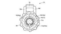
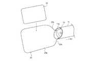
図1ないし図6は、本発明によるスライド部材の進退機構10の第1の実施形態を示している。断面円形の外筒11内には、スライド部材(軸部材)12が軸方向に移動自在に挿入されている。外筒11の先端部はこの例では軸線直交方向に対して傾斜した斜面である。また、図示例では、スライド部材12の先端部には別部材としての支持部材13が設けられている。この支持部材13はスライド部材12と相対回転せず一緒に軸方向に移動するものであり、スライド部材12の一部である。 1 to 6 show a first embodiment of a slide member advance /
スライド部材12の後端部には一体に、軸対称ラック14が形成されている。軸対称ラックとはスライド部材12の軸を中心とする回転対称形状にラックを形成したものである。スライド部材12には、この軸対称ラック14の一部を除去して、軸線と平行な方向に延びるキー溝14aが形成されている。 An
一方、外筒11の後端部外周には、該外筒11と一体に結合される(外筒11の一部である)端部環11aが嵌合固定されており、この端部環11aの内周面に、キー溝14aに係合するキー突起11bが形成されている。端部環11aは外筒11と一体に成形してもよい。スライド部材12の軸対称ラック14は、端部環11a(外筒11の後端部)から突出している(させることができる)。 On the other hand, on the outer periphery of the rear end portion of the
スライド部材12の軸対称ラック14に外筒11からの突出端において噛み合うピニオン(操作輪)15は、一対の半割ピニオンホルダ(操作輪ホルダ)16の間に回転自在に支持されている。各半割ピニオンホルダ16は、半円筒状部16aと、この半円筒状部16aから径方向に延びるピニオン支持アーム16bとを有し、一方のピニオン支持アーム16bに、ピニオン15の軸穴15aに挿入される軸突起16c(図3)が形成されている。軸穴15a(軸突起16c)は、外筒11及びスライド部材12の軸線に交わらずに直交している。また、一対の半割ピニオンホルダ16には、その端部環11a側の端部に半割内方フランジ16d(図3)が形成されており、この半割内方フランジ16dが外筒11の環状溝11cに嵌まる。一対の半割ピニオンホルダ16を組み合わせ、一対の半割内方フランジ16dを環状溝11cに嵌め、一対のピニオン支持アーム16bの間にピニオン15を位置させて軸穴15aに軸突起16cを挿入すると、ピニオン15の歯15bが軸対称ラック14と噛み合い、しかも結合された半割ピニオンホルダ(ピニオンホルダ)16を外筒11(スライド部材12)の軸線回りに回動させることができる。ピニオンホルダ16をスライド部材12の軸線回りのどの位置に回動させても歯15bと軸対称ラック14の噛合は維持される。 A pinion (operating wheel) 15 that meshes with the
一対の半割ピニオンホルダ16の前後にはそれぞれ、その外周面に全体として環状のOリング溝16fを形成する半環状溝16gが形成されている。一対の半割ピニオンホルダ16は組み合わせた状態においてそのOリング溝16fにOリング18を嵌めることにより、仮に結合される。またこのとき、一対の半割ピニオンホルダ16の後端部の間には、スライド部材12の軸対称ラック14が進退する後方保護パイプ19が挟まれて固定される。 A
前方結合環20と後方結合環21は、前後に外筒11と後方保護パイプ19を保持した一対の半割ピニオンホルダ16を本結合するものである。すなわち、前方結合環20と後方結合環21は、外筒11と後方保護パイプ19を挟着した一対の半割ピニオンホルダ16を前後のOリング18で仮結合した状態において、該外筒11と後方保護パイプ19の外周に嵌められ、半割ピニオンホルダ16側にスライドされる。前方結合環20と後方結合環21の内周面には、半割ピニオンホルダ16のOリング溝16f(半環状溝16g)に対応する環状溝20aと21aが形成されており、結合環20(21)の端部がOリング18に達すると、図6に示すように、Oリング18が一旦押し潰され、次いでOリング溝16f(半環状溝16g)と環状溝20a(21a)の位置が一致すると、Oリング18が復元し、本結合作業が完了する。この本結合作業が完了すると、通常の使用状態で前方結合環20と後方結合環21が半割ピニオンホルダ16から抜けることはないが、逆の動作で分解することもできる。前方結合環20と端部環11aには、両者の嵌合状態で互いに嵌合し相対回動を防ぐ回り止め突起(図示せず)と回り止め溝11d(図5)が形成されている。また、前方結合環20には、外筒11の方向(回転位相)を示す指標20b(図1、図5)が付されている。 The
上記構成の本スライド部材の進退機構10は、ピニオンホルダ16及びピニオン15が外筒11及びスライド部材12の軸線に対してそれぞれ相対回動自在で、該スライド部材12に外筒11内での直進進退動作を与える操作部を構成している。すなわち、外筒11の方向(回転位相)を基準としたとき、該外筒11の軸線に対してピニオンホルダ16を任意の回転位相に回転させることができる。そして、任意の回転位置でピニオン15を正逆に回転操作すると、キー突起11bとキー溝14aにより外筒11内で直進案内されたスライド部材12が、歯15bと軸対称ラック14の噛合により、正逆に直進進退する。 The slide member advancing /
図7ないし図9は、本発明によるスライド部材の進退機構10Aの第2の実施形態を示すもので、第1の実施形態に対応する構成要素には同一の符号を付している。この実施形態では、外筒11内に挿入されたスライド部材12にキー溝12aが形成され、外筒11の内面にキー突起11bが形成されている。 7 to 9 show a second embodiment of a slide member advance /
スライド部材12の後端部には、相対回動スライド部材12Xが相対回動は自在で軸方向には一緒に移動するように結合されている。この結合態様は、図8に示すように、スライド部材12の後端部に小径軸部12cと大径円板部12dを順に形成する一方、相対回動スライド部材12Xの前端部に、小径軸部12cと大径円板部12dを径方向から回転自在に軸方向移動を拘束して受け入れる小径溝12fと大径溝12gを形成したものである。この相対回動スライド部材12Xには、その後端部に、ラック14Xが形成されている。このラック14Xは、相対回動スライド部材12Xの周面の一部に直線状に形成した通常のラックである。 A relative
外筒11の後端部に固定した端部環11aには、第1の実施形態と同様の一対の半割ピニオンホルダ16が軸線回りに回転自在に支持されている。すなわち、端部環11aに形成した環状溝11cに、半割ピニオンホルダ16の半割内方フランジ16dが相対回動自在に嵌まっている。この実施形態では、一対の半割ピニオンホルダ16は接着、ねじ締め等によりい互いに固定されるものであり、両者の間に、相対回動スライド部材12Xのラック14Xに噛み合うピニオン15が回転自在に支持されている。 A pair of
この第2の実施形態のスライド部材の進退機構10Aによると、相対回転しない外筒11とスライド部材12に対して、相対回動スライド部材12X及び半割ピニオンホルダ16が相対回動できる。つまり、半割ピニオンホルダ16及びピニオン15は、外筒11及びスライド部材12に対してそれぞれ相対回動自在で、該スライド部材12に外筒11内での直進進退動作を与える操作部を構成しており、外筒11の方向(回転位相)を基準としたとき、該外筒11の軸線に対して半割ピニオンホルダ16を任意の回転位相に回転させることができる。そして、任意の回転位置でピニオン15を正逆に回転操作すると、キー突起11bとキー溝12aにより外筒11内で直進案内されたスライド部材12が、歯15bとラック14Xの噛合により、直進進退する。 According to the slide member advance /
以上の第1、第2の実施形態において、ピニオン15は摩擦車に代え、軸対称ラック14はこの摩擦車に摩擦接触する摩擦円柱に代え、ラック14Xは、摩擦板(部材)に代えても同様の作用を得ることができる。 In the first and second embodiments described above, the
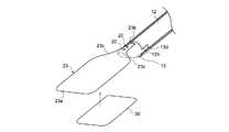
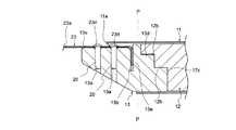
本発明のスライド部材の進退機構は、その用途を問わないものであるが、次に、より具体的な適用態様を図10ないし図18で説明する。この例は、スライド部材12の先端部の支持部材13に、内視鏡処置術(より詳しくは、腹腔鏡下手術や胸腔鏡下手術に際して予め体内に挿入されたトラカールを介して外筒11を挿入して行う)で患部にシート状の治療用物質30(図10、図14、以下、シート30と呼ぶ)を運搬し貼付するためのシート支持体23を支持した例である。以下の説明における「軸線方向」及び「径方向」とは、外筒11の軸線方向(長手方向)と径方向を意味する。外筒11の先端部は、外筒11の軸線と直交する平面P(図11に一点鎖線で示す)に対して傾斜された傾斜端面11aになっている。この平面Pに対する傾斜端面11aの傾き角は、約30度である。傾斜端面11aには面取り加工がなされていて、滑らかな先端形状になっている。 The slide member advance / retreat mechanism according to the present invention may be used for any purpose. Next, more specific application modes will be described with reference to FIGS. In this example, the
シート支持体23は、弾性を有する薄板状体であり、シート30を支持するシート支持面部23aと、該シート支持面部23aの基端部に位置する接続部23bと、シート支持面部23aから接続部23bに向けて徐々に幅を狭くしていく幅徐変部23cとを有している。幅徐変部23cは、外筒11の軸線を挟んで略対称な形状をなす一対の側縁部を有し、それぞれの側縁部は、シート支持面部23aに連続する凸状の円弧部(R面)と、接続部23bに続く凹状の円弧部(R面)を組み合わせて構成されている。シート支持体23は、外力を加えない自由状態では、図10及び図14に示すように、シート支持面部23aが平面状に展開された形状に維持される。 The
シート支持体23とスライド部材12は支持部材13を介して接続される。図10ないし図13に示すように、支持部材13は、先端部側から順に、2つのねじ孔13a、差し込み溝13b、嵌合段部13cを有し、嵌合段部13c上には離間移動規制突起13dが形成されている。ねじ孔13aの形成領域には、外筒11の軸線と略平行をなす支持平面13eが形成されている。シート支持体23の接続部23bには、支持部材13の2つのねじ孔13aに重なる位置関係で2つの貫通孔23dが形成され、接続部23bの末端部には差し込み溝13bに係合可能な終端曲げ部23eが折り曲げ形成されている。終端曲げ部23eを差し込み溝13bに係合させて接続部23bを支持平面13e上に載せると、2つの貫通孔23dが2つのねじ孔13aと重なって位置される。ここで各貫通孔23dを通して各ねじ孔13aに固定ねじ20を螺合させることにより、シート支持体23と支持部材13が固定される。または、固定ねじ20の代わりにピンを圧入することでシート支持体23と支持部材13を固定してもよい。 The
スライド部材12の先端は、支持部材13の嵌合段部13cに嵌合する嵌合段部12hとなっており、この嵌合段部12hに、離間移動規制突起13dが嵌合する形状の離間移動規制凹部12b(図11に断面のみ示す)が形成されている。支持部材13に設けた離間移動規制突起13dは、図12に示すように、スライド部材12の先端側から基端側(操作部側)に向かうにつれて徐々に幅を大きくする台形状の突起である。そのため、軸線方向において離間する方向へのスライド部材12と支持部材13の相対移動は、離間移動規制凹部12bと離間移動規制突起13dの嵌合関係によって規制される。一方、嵌合段部12hと嵌合段部13cは、互いの端面の当接関係によって、軸線方向において互いに接近する方向へのスライド部材12と支持部材13の相対移動を規制する。すなわち、スライド部材12と支持部材13は、軸線方向の正逆いずれの方向にも相対移動しないように連結される。この連結構造は、径方向への相対移動によって解除可能である。 The front end of the
スライド部材12と支持部材13の連結部分は、図10及び図11に示すように外筒11の内周面によって囲まれる位置にある。支持部材13はスライド部材12に対して、外筒11の軸線方向には相対移動が規制され、外筒11の径方向にのみ分解可能であるが、図11のように、スライド部材12と支持部材13の後部が外筒11に位置する通常の使用状態では、スライド部材12と支持部材13が分解可能状態になることがない。 The connecting portion of the
一方、スライド部材12と支持部材13をさらに外筒11から突出させると、外筒11による規制が解除されて、図12に示すように支持部材13をスライド部材12から取り外すことが可能になる。 On the other hand, when the
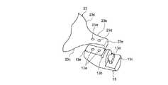
図14は、通常使用状態の最大突出位置までスライド部材12を押し出した状態を示しており、この状態でシート支持体23は外筒11の先端から突出されて、その形状維持性(弾性)によりシート支持面部23aを平面状に展開させている。展開された状態のシート支持体23は、外筒11の内径サイズよりも広い幅を有している。図14の状態から矢印S1で示す引き込み方向へスライド部材12をスライドさせると、図15に示すようにシート支持体23の幅徐変部23cが外筒11の傾斜端面11aに接触する。すると、傾斜端面11aと幅徐変部23cのそれぞれの傾斜形状によって、スライド部材12の軸線方向移動力からシート支持体23を筒状に丸めようとする分力F(図15)が生じる。このとき筒状になろうとするシート支持体23の内側の面が、シート30を支持する支持面となる。 FIG. 14 shows a state in which the
図15の状態からスライド部材12の引き込み動作を継続すると、図16、図17と順を追って示すように、スライド部材12の移動に応じてシート支持体23は、外筒11の内周面形状に沿う円筒形状に丸められながら外筒11内に収納されていく。図16の段階ではまだ幅徐変部23cが傾斜端面11aに当接しており、スライド部材12の軸線方向移動力に応じてシート支持体23を筒状に丸めようとする分力が作用している。図17の段階まで至ると幅徐変部23cは外筒11内に収納された状態になるが、このとき外筒11の先端部(傾斜端面11aの開口部)においては、シート支持面部23aの両側部が互いに隣接した状態まで接近されて、シート支持体23は概ね筒状形状への変形が完了している、よって、図17の状態からスライド部材12を引き込み方向へスライドさせても、シート支持体23は、傾斜端面11aとの間で引っ掛かりを生じることなく、シート支持面部23aの先端部側に向けて徐々に円筒状に丸まりながら外筒11内に収納されていく。 When the retracting operation of the
図18はシート支持体23の全体が外筒11内に収納された状態であり、シート支持体23は外筒11の内周面に沿う筒状形状に変形されている。シート支持体23は、この筒状の収納状態において、自身の一部が重なることがないように幅寸法が定められている。具体的には、外筒11の内径サイズが直径9.5mmである場合、シート支持体23の横幅サイズが229m 程度であると、重なりを生じることなく外筒11の内周面に沿って筒状に収納することができる。 FIG. 18 shows a state where the
以上の収納時とは逆に、図18の収納状態からスライド部材12を矢印S2で示す突出方向へスライドさせると、シート支持体23はその形状復元性(弾性)によって、外筒11から突出する部分を徐々に平面方向に拡げていき、図17の状態、図16の状態、図15の状態と変形していく。そして、図14の最大突出位置までスライド部材12を移動させると、幅徐変部23cが傾斜端面11aから離れて外筒11によるシート支持体23への形状規制が解除され、自由状態となったシート支持面部23aが平面状に展開される。 Contrary to the above storage, when the
従って、体内に外筒11を挿入する前にシート支持面部23aにシート30を保持しておき、体内に外筒11を挿入した後、患部においてシート支持面部23aを展開し、シート30を患部に移植することができる。 Accordingly, the
シート支持体23は、例えば、ポリプロピレン、アクリル樹脂、ポリエチレンテレフタラート、ポリエチレンといった材質からなる適当な厚さの樹脂フィルム、あるいは、シリコンゴムや、超弾性合金、形状記憶合金などの金属製の薄板によって形成することができる。また、使用時の利便性を考慮した場合、シート支持体23は透明もしくは半透明であることが好ましい。透明であると、シート支持面部23a上に支持されたシート30の状態を裏面側からでも観察することができる。また、シート移植作業中において、シート支持体23を通して患部の位置を視認してシート30の位置合わせを容易に行うことができる。 The
以上のようにシート支持体23は、スライド部材12の進退移動に応じて平面状の展開形状と筒状形状に変形されるものであり、外筒11から突出されたときに平面状に展開される形状維持(復元)性を備えている。このときのシート支持体23の平面方向は、外筒11の方向(回転位相)で定まり、その方向は、外筒11の指標20bによって知ることができる。一方、図1ないし図9に示した操作部(ピニオンホルダ16及びピニオン15)は、外筒11(スライド部材12)の軸線中心に対して回動可能であり、どの回動位置でも、スライド部材12を進退移動させることができるので、使い勝手がよい。さらに、ピニオン15を回転させる力は、外筒11と直交する方向からピニオン15に加わるので、スライド部材12を軸方向に進退動作させる際、外筒11とスライド部材12を不用意に軸線方向に移動させることがない。すなわち、外筒11の先端部及びスライド部材12の先端部の位置を正確に制御することができ、内視鏡手術の精度を高めることができる。 As described above, the
以上のシート支持体23は、本発明のスライド部材の進退機構の好ましい適用例として説明したが、本発明の用途がこれに限定されないことは勿論である。 Although the above-mentioned
なお、本発明のスライド部材の進退機構を内視鏡処置具としてのシート支持体23の進退機構に用いる場合、スライド部材12に対して脱着可能なシート支持体23と支持部材13の結合体は、使用毎に新しいものに交換される。これに対し、外筒11やスライド部材12からなる本体部は、繰り返しの使用に耐えうる強度、構造をもち滅菌処理に対応する材質(ステンレスなど)で形成し、使用後に滅菌処理を行って再使用してもよい。これにより、使い捨て部分を少なくして環境対策を図ると共に運用コストを下げることが可能となる。 In addition, when using the advance / retreat mechanism of the slide member of the present invention for the advance / retreat mechanism of the
10 10A スライド部材の進退機構
11 外筒
11a 端部環
11b キー突起
11c 環状溝
11d 回り止め溝
12 スライド部材
12X 相対回動スライド部材
12a キー溝
12d 係合段部
13 支持部材
14 軸対称ラック
14a キー溝
14X ラック
15 ピニオン(操作輪)
15a 軸穴
15b 歯
16 半割ピニオンホルダ(操作輪ホルダ)
16a 半円筒状部
16b ピニオン支持アーム
16c 軸突起
16d 半割内方フランジ
16f Oリング溝
16g 半環状溝
18 Oリング
19 後方保護パイプ
20 前方結合環
21 後方結合環
20a 21a 環状溝
20b 指標10 10A Slide member advance /
16a
Claims (5)
Translated fromJapanese該外筒内に相対回転を拘束して軸線方向へ摺動可能に支持されたスライド部材;
外筒及びスライド部材に対してそれぞれ相対回動自在で、該スライド部材に外筒内での直進進退動作を与える操作部;
を有することを特徴とするスライド部材の進退機構。Outer cylinder;
A slide member supported in the outer cylinder so as to be slidable in the axial direction while restraining relative rotation;
An operating portion that is rotatable relative to the outer cylinder and the slide member, respectively, and that gives the slide member a linear advance / retreat operation within the outer cylinder;
A sliding member advancing and retracting mechanism characterized by comprising:
Priority Applications (2)
| Application Number | Priority Date | Filing Date | Title |
|---|---|---|---|
| JP2008008634AJP2009165717A (en) | 2008-01-18 | 2008-01-18 | Advance and retreat mechanism of slide member |
| US12/349,600US20090187168A1 (en) | 2008-01-18 | 2009-01-07 | Slide member advancing/retracting mechanism |
Applications Claiming Priority (1)
| Application Number | Priority Date | Filing Date | Title |
|---|---|---|---|
| JP2008008634AJP2009165717A (en) | 2008-01-18 | 2008-01-18 | Advance and retreat mechanism of slide member |
Publications (1)
| Publication Number | Publication Date |
|---|---|
| JP2009165717Atrue JP2009165717A (en) | 2009-07-30 |
Family
ID=40877039
Family Applications (1)
| Application Number | Title | Priority Date | Filing Date |
|---|---|---|---|
| JP2008008634AWithdrawnJP2009165717A (en) | 2008-01-18 | 2008-01-18 | Advance and retreat mechanism of slide member |
Country Status (2)
| Country | Link |
|---|---|
| US (1) | US20090187168A1 (en) |
| JP (1) | JP2009165717A (en) |
Cited By (5)
| Publication number | Priority date | Publication date | Assignee | Title |
|---|---|---|---|---|
| WO2011007773A1 (en) | 2009-07-14 | 2011-01-20 | 国立大学法人神戸大学 | Mutant ras polypeptide crystal |
| WO2024117248A1 (en)* | 2022-12-02 | 2024-06-06 | テルモ株式会社 | Transfer instrument |
| WO2024117249A1 (en)* | 2022-12-02 | 2024-06-06 | テルモ株式会社 | Transfer instrument |
| WO2024117247A1 (en)* | 2022-12-02 | 2024-06-06 | テルモ株式会社 | Transfer instrument |
| WO2024117250A1 (en)* | 2022-12-02 | 2024-06-06 | テルモ株式会社 | Transfer instrument |
Families Citing this family (5)
| Publication number | Priority date | Publication date | Assignee | Title |
|---|---|---|---|---|
| EP2961462A4 (en) | 2013-02-27 | 2017-01-18 | The George Washington University | Ultrasound assisted catheter placement system |
| US10143826B2 (en) | 2014-10-31 | 2018-12-04 | SonoStik LLC | Wire introduction device for introducing guide wire |
| EP3297548B1 (en) | 2015-06-25 | 2020-05-06 | Gyrus Acmi Inc., D.B.A. Olympus Surgical Technologies America | Retraction force sensing basket |
| US11559662B2 (en)* | 2018-04-13 | 2023-01-24 | Merit Medical Systems, Inc. | Steerable drainage devices |
| CA3209559A1 (en)* | 2018-10-03 | 2020-04-09 | Conmed Corporation | Soft tissue cutting instrument with self locking, multi-position, and slide button linearly actuated retractable blade or hook |
Citations (2)
| Publication number | Priority date | Publication date | Assignee | Title |
|---|---|---|---|---|
| JPH02271850A (en)* | 1990-03-20 | 1990-11-06 | Olympus Optical Co Ltd | Forceps for crushing calculus |
| JPH10113351A (en)* | 1996-09-12 | 1998-05-06 | Ethicon Endo Surgery Inc | Surgical fastening mechanism |
Family Cites Families (10)
| Publication number | Priority date | Publication date | Assignee | Title |
|---|---|---|---|---|
| CA2090000A1 (en)* | 1992-02-24 | 1993-08-25 | H. Jonathan Tovey | Articulating mesh deployment apparatus |
| US5304187A (en)* | 1992-06-30 | 1994-04-19 | United States Surgical Corporation | Surgical element deployment apparatus |
| US5968052A (en)* | 1996-11-27 | 1999-10-19 | Scimed Life Systems Inc. | Pull back stent delivery system with pistol grip retraction handle |
| US6866669B2 (en)* | 2001-10-12 | 2005-03-15 | Cordis Corporation | Locking handle deployment mechanism for medical device and method |
| US7052511B2 (en)* | 2002-04-04 | 2006-05-30 | Scimed Life Systems, Inc. | Delivery system and method for deployment of foreshortening endoluminal devices |
| US7892283B2 (en)* | 2005-04-08 | 2011-02-22 | Abbott Medical Optics Inc. | Methods and apparatus for inserting an intraocular lens into an eye |
| US8025621B2 (en)* | 2005-07-26 | 2011-09-27 | Microline Surgical, Inc. | Medical device with adjustable inner shaft movement |
| US20070185504A1 (en)* | 2005-08-25 | 2007-08-09 | Microline Pentax, Inc. | Medical clip feeding mechanism |
| US20070049950A1 (en)* | 2005-08-25 | 2007-03-01 | Microline Pentax Inc. | Medical clip applying device |
| US7985197B2 (en)* | 2007-05-22 | 2011-07-26 | Hoya Corporation | Therapeutic-substance carrying/administering appliance |
- 2008
- 2008-01-18JPJP2008008634Apatent/JP2009165717A/ennot_activeWithdrawn
- 2009
- 2009-01-07USUS12/349,600patent/US20090187168A1/ennot_activeAbandoned
Patent Citations (2)
| Publication number | Priority date | Publication date | Assignee | Title |
|---|---|---|---|---|
| JPH02271850A (en)* | 1990-03-20 | 1990-11-06 | Olympus Optical Co Ltd | Forceps for crushing calculus |
| JPH10113351A (en)* | 1996-09-12 | 1998-05-06 | Ethicon Endo Surgery Inc | Surgical fastening mechanism |
Cited By (5)
| Publication number | Priority date | Publication date | Assignee | Title |
|---|---|---|---|---|
| WO2011007773A1 (en) | 2009-07-14 | 2011-01-20 | 国立大学法人神戸大学 | Mutant ras polypeptide crystal |
| WO2024117248A1 (en)* | 2022-12-02 | 2024-06-06 | テルモ株式会社 | Transfer instrument |
| WO2024117249A1 (en)* | 2022-12-02 | 2024-06-06 | テルモ株式会社 | Transfer instrument |
| WO2024117247A1 (en)* | 2022-12-02 | 2024-06-06 | テルモ株式会社 | Transfer instrument |
| WO2024117250A1 (en)* | 2022-12-02 | 2024-06-06 | テルモ株式会社 | Transfer instrument |
Also Published As
| Publication number | Publication date |
|---|---|
| US20090187168A1 (en) | 2009-07-23 |
Similar Documents
| Publication | Publication Date | Title |
|---|---|---|
| JP2009165717A (en) | Advance and retreat mechanism of slide member | |
| CN108697428B (en) | Fixture box | |
| US10716547B2 (en) | Adapter for attaching devices to endoscopes | |
| JP6967548B2 (en) | Devices to apply surgical clips | |
| US20190046202A1 (en) | Geared actuation mechanism and surgical clip applier including the same | |
| JP5042029B2 (en) | Endoscopic treatment tool | |
| BRPI0601359B1 (en) | SURGICAL CLICK APPLICATOR | |
| JP6663992B2 (en) | Endoscope treatment tool | |
| WO2016157565A1 (en) | Endoscope clip device and clip | |
| JP2009095471A (en) | Clip device of endoscope | |
| JP2010269126A (en) | Ultrasound endoscope puncture needle device | |
| CN105208949A (en) | Medical device handles and related methods of use | |
| CN113599040A (en) | Front-end rear-release mechanism of interventional stent conveyor, conveyor and using method | |
| JP2015149997A (en) | Endoscopic clip device, endoscopic clip device kit and clip | |
| CN109044433B (en) | Continuous stitching instrument for laparoscopic stitching operation | |
| WO2016151931A1 (en) | Treatment instrument for endoscope | |
| JP5271798B2 (en) | Ultrasound endoscope puncture needle device | |
| JP2009056054A (en) | Endoscope guiding tube device | |
| JP2009240774A (en) | Treatment instrument for endoscopic use | |
| JP2010207340A (en) | Endoscope guiding tube device | |
| US20170065151A1 (en) | Endoscope | |
| JPWO2018011855A1 (en) | Treatment tool for endoscope | |
| JPH01113070A (en) | Treatment jig for endoscope | |
| JP2012050490A (en) | Wire operation device | |
| JP6407482B2 (en) | Advancement / retraction aid for treatment tool, endoscope system |
Legal Events
| Date | Code | Title | Description |
|---|---|---|---|
| A621 | Written request for application examination | Free format text:JAPANESE INTERMEDIATE CODE: A621 Effective date:20100823 | |
| A977 | Report on retrieval | Free format text:JAPANESE INTERMEDIATE CODE: A971007 Effective date:20120627 | |
| A131 | Notification of reasons for refusal | Free format text:JAPANESE INTERMEDIATE CODE: A131 Effective date:20120710 | |
| A761 | Written withdrawal of application | Free format text:JAPANESE INTERMEDIATE CODE: A761 Effective date:20120821 |