JP2009160721A - Motorized rotary joint - Google Patents
Motorized rotary jointDownload PDFInfo
- Publication number
- JP2009160721A JP2009160721AJP2008003324AJP2008003324AJP2009160721AJP 2009160721 AJP2009160721 AJP 2009160721AJP 2008003324 AJP2008003324 AJP 2008003324AJP 2008003324 AJP2008003324 AJP 2008003324AJP 2009160721 AJP2009160721 AJP 2009160721A
- Authority
- JP
- Japan
- Prior art keywords
- frame
- rotor
- casing
- electric motor
- rotating shaft
- Prior art date
- Legal status (The legal status is an assumption and is not a legal conclusion. Google has not performed a legal analysis and makes no representation as to the accuracy of the status listed.)
- Granted
Links
- 239000003638chemical reducing agentSubstances0.000claimsabstractdescription18
- 230000002093peripheral effectEffects0.000claimsabstractdescription15
- XEEYBQQBJWHFJM-UHFFFAOYSA-NIronChemical compound[Fe]XEEYBQQBJWHFJM-UHFFFAOYSA-N0.000description2
- 238000009434installationMethods0.000description2
- 239000012212insulatorSubstances0.000description2
- 239000011347resinSubstances0.000description2
- 229920005989resinPolymers0.000description2
- 230000004323axial lengthEffects0.000description1
- 238000001514detection methodMethods0.000description1
- 239000000428dustSubstances0.000description1
- 229910052742ironInorganic materials0.000description1
- 238000010030laminatingMethods0.000description1
- 239000000696magnetic materialSubstances0.000description1
- 239000006247magnetic powderSubstances0.000description1
- 230000013011matingEffects0.000description1
- 239000002184metalSubstances0.000description1
- 229910052751metalInorganic materials0.000description1
- 230000004048modificationEffects0.000description1
- 238000012986modificationMethods0.000description1
- 230000003287optical effectEffects0.000description1
- 230000000149penetrating effectEffects0.000description1
- 239000013585weight reducing agentSubstances0.000description1
Images

Landscapes
- Manipulator (AREA)
- Connection Of Motors, Electrical Generators, Mechanical Devices, And The Like (AREA)
Abstract
Description
Translated fromJapaneseこの発明は、2つのフレームを回動可能に連結する電動回転継手に関するものである。 The present invention relates to an electric rotary joint that rotatably connects two frames.
例えば、多関節型ロボットなどの産業用ロボットにおいては、一方のフレームと他方のフレームとを回動自在に連結する連結部に電動回転継手を設けたものがある。
この種の電動回転継手は、各フレームを駆動させるための電動モータを有し、この電動モータの駆動力を減速機を介して一方のフレーム、または他方のフレームの何れかに伝達するように構成されている。For example, some industrial robots such as articulated robots are provided with an electric rotary joint at a connecting portion that rotatably connects one frame and the other frame.
This type of electric rotary joint has an electric motor for driving each frame, and is configured to transmit the driving force of this electric motor to one of the frames or the other frame via a reduction gear. Has been.
電動モータは、ケーシングと、このケーシングに固定されている固定子と、固定子に対して回転自在に設けられた回転子とを備えている。固定子には複数のティースが放射状に突設されており、各ステータにコイルが巻装されている。回転子はケーシングに回転自在に支持されている回転軸を有し、この回転軸に回転子本体が外嵌固定されている。回転子本体には、固定子のティースに対向する部位に永久磁石が設けられている。 The electric motor includes a casing, a stator fixed to the casing, and a rotor provided to be rotatable with respect to the stator. The stator is provided with a plurality of teeth projecting radially, and a coil is wound around each stator. The rotor has a rotating shaft that is rotatably supported by the casing, and the rotor body is fitted and fixed to the rotating shaft. The rotor body is provided with a permanent magnet at a portion facing the teeth of the stator.
また、電動モータは、ケーシングを一方のフレームに固定すると共に、回転軸を減速機を介して他方のフレームに連係してある。このように電動モータを取付けることで、電動モータを駆動させた際、各フレームを回動軸を中心にして回動させることができる(例えば、特許文献1、特許文献2参照)。
しかしながら、上述の従来技術にあっては、電動モータのケーシングをフレームに固定する必要があるため、ケーシングの設置スペースを確保する分、フレーム同士を連結する連結部が大型化してしまうという課題がある。 However, in the above-described prior art, since it is necessary to fix the casing of the electric motor to the frame, there is a problem that the connecting portion for connecting the frames to each other is increased by securing the installation space of the casing. .
そこで、この発明は、上述した事情に鑑みてなされたものであって、2つのフレームを互いに回動可能に連結し、両者を電動モータを用いて駆動させる連結部分を小型化することができると共に、連結部分を軽量化することができる電動回転継手を提供するものである。 Accordingly, the present invention has been made in view of the above-described circumstances, and can reduce the size of a connecting portion that connects two frames so as to be rotatable with each other and drives both using an electric motor. An electric rotary joint capable of reducing the weight of the connecting portion is provided.
上記の課題を解決するために、請求項1に記載した発明は、一方のフレームと他方のフレームとを電動モータ、および減速機を介して回動可能に連結した電動回転継手において、前記電動モータは、ケーシングと、前記ケーシングに固定された固定子と、前記固定子に対して回転自在に設けられ中空状の回転軸を有する回転子とを備え、前記一方のフレームと前記ケーシングとを一体成形し、前記他方のフレームを前記減速機を介して前記回転子と連係し、前記回転子は、略円盤状の回転子本体を有し、前記回転子本体の外周面に永久磁石を設け、前記回転子本体の径方向中央に前記回転軸を内嵌固定するための軸孔を形成し、前記回転子本体の軸線方向両端面であって前記永久磁石と前記軸孔との間に、それぞれ環状の凹部を形成したことを特徴とする。
このように構成することで、一方のフレームを電動モータのケーシングと共有することができる。
また、回転軸を中空状に形成することで、電動モータの質量を低減することができると共に、回転軸の内部に配線などを配索させることが可能になる。
さらに、回転子本体に環状の凹部を形成することで、回転子の軽量化を図ることができると共に、凹部に回転子の回転角度を検出するセンサを配置することができる。In order to solve the above problems, the invention described in claim 1 is directed to an electric rotary joint in which one frame and the other frame are connected to each other via an electric motor and a reduction gear so as to be rotatable. Includes a casing, a stator fixed to the casing, and a rotor having a hollow rotation shaft that is rotatably provided with respect to the stator, and integrally forms the one frame and the casing. The other frame is linked to the rotor via the speed reducer, and the rotor has a substantially disc-shaped rotor body, and a permanent magnet is provided on the outer peripheral surface of the rotor body. A shaft hole for internally fitting and fixing the rotating shaft is formed at the radial center of the rotor main body, and each of the rotor main body has an annular shape between the permanent magnet and the shaft hole. Having formed a recess And features.
By comprising in this way, one flame | frame can be shared with the casing of an electric motor.
In addition, by forming the rotating shaft in a hollow shape, it is possible to reduce the mass of the electric motor and to wire the inside of the rotating shaft.
Furthermore, by forming an annular recess in the rotor body, the weight of the rotor can be reduced, and a sensor for detecting the rotation angle of the rotor can be disposed in the recess.
請求項2に記載した発明は、前記減速機は、前記回転軸の外周面に取付けられたウェーブジェネレータと、このウェーブジェネレータの外周に配置され前記他方のフレームに取付けられたフレクスプラインと、前記フレクスプラインの外周に配置され前記ケーシングに取付けられたサーキュラスプラインとで構成され、前記フレクスプラインと前記サーキュラスプラインとが噛合されていることを特徴とする。
このように構成することで、減速機の径方向中心に空間を確保することができるので、この空間に配線などを配索することが可能になる。According to a second aspect of the present invention, the speed reducer includes a wave generator attached to the outer peripheral surface of the rotating shaft, a flex spline arranged on the outer periphery of the wave generator and attached to the other frame, and the flex It is comprised by the circular spline arrange | positioned on the outer periphery of a spline, and was attached to the said casing, The said flexspline and the said circular spline are meshing | engaged, It is characterized by the above-mentioned.
With this configuration, a space can be secured at the radial center of the speed reducer, so that wiring or the like can be routed in this space.
請求項1に記載した発明によれば、一方のフレームを電動モータのケーシングと共有することができる。このため、一方のフレームと他方のフレームとの連結部分を小型することができると共に、軽量化することが可能になる。
また、回転軸を中空状に形成することで、電動モータの質量を低減することができると共に、回転軸の内部に配線などを配索させることが可能になる。このため、さらに一方のフレームと他方のフレームとの連結部分を小型することができる。
さらに、回転子本体に環状の凹部を形成することで、回転子の軽量化を図ることができると共に、凹部に回転子の回転角度を検出するセンサを配置することができる。このため、電動モータを軽量化できるだけでなく、センサの設置スペースを回転子の内側に設定することができるので、電動モータの扁平化を図ることができる。According to the first aspect of the present invention, one frame can be shared with the casing of the electric motor. For this reason, the connecting portion between one frame and the other frame can be reduced in size and can be reduced in weight.
In addition, by forming the rotating shaft in a hollow shape, it is possible to reduce the mass of the electric motor and to wire the inside of the rotating shaft. For this reason, the connection part of one frame and the other frame can be further reduced in size.
Furthermore, by forming an annular recess in the rotor body, the weight of the rotor can be reduced, and a sensor for detecting the rotation angle of the rotor can be disposed in the recess. For this reason, not only can the electric motor be reduced in weight, but also the sensor installation space can be set inside the rotor, so that the electric motor can be flattened.
請求項2に記載した発明によれば、減速機の径方向中心に空間を確保することができるので、この空間に配線などを配索することが可能になる。このため、さらに一方のフレームと他方のフレームとの連結部分を小型することができる。 According to the second aspect of the present invention, since a space can be secured at the radial center of the speed reducer, it is possible to route a wiring or the like in this space. For this reason, the connection part of one frame and the other frame can be further reduced in size.
次に、この発明の実施形態を図面に基づいて説明する。
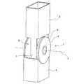
図1〜図3に示すように、電動回転継手1は、例えば、多関節型ロボットなどの産業用ロボットの関節部分に用いられるものであって、第一フレーム2と第二フレーム3とを回動可能に連結している。第一フレーム2、および第二フレーム3は、両端が閉塞された筒状を有しており、断面略四角形状に形成されている。また、第一フレーム2、および第二フレーム3は、互いに同一直線上に並設された状態になっており、この直線に交差する軸線Jを中心に回動するようになっている。Next, embodiments of the present invention will be described with reference to the drawings.
As shown in FIGS. 1 to 3, the electric rotary joint 1 is used, for example, in a joint portion of an industrial robot such as an articulated robot, and rotates the first frame 2 and the
電動回転継手1は、電動モータ4と、この電動モータ4の回転軸5に取付けられた減速機6とで構成されている。この回転軸5の軸心が軸線Jに一致している。
電動モータ4は、ケーシング9と、ケーシング9に固定された固定子10と、固定子10の径方向内側に回転自在に設けられている回転子11とを備えた所謂インナーロータ型のブラシレスモータである。
ケーシング9は、互いに有底筒状に形成されているフロントブラケット7、およびリヤブラケット8で構成され、これらフロントブラケット7、およびリヤブラケット8を互いに重ね合わせることによって固定子10を固定している。The electric rotary joint 1 includes an
The
The casing 9 includes a
フロントブラケット7は、第一フレーム2と一体成形されており、第一フレーム2の一部がフロントブラケット7を兼ねた状態になっている。フロントブラケット7の固定子10に対応する部位には、段差によって拡径された拡径部12が形成されており、ここに固定子10の外周部が圧入固定されている。
フロントブラケット7の径方向中央には、軸受けハウジング13が形成されており、ここに回転軸5の一端側を回転自在に支持する軸受け14が設けられている。
このように、第一フレーム2とフロントブラケット7を一体成形することにより、第一フレーム2の一部をフロントブラケット7とする構成により、第一フレーム2に固定子10および回転軸5を保持する機能を備えることができる。The
A bearing
As described above, the first frame 2 and the
一方、リヤブラケット8は樹脂で形成されている。リヤブラケット8の径方向中央には、軸受けハウジング16が形成されており、ここに回転軸5の他端側を回転自在に支持する軸受け17が設けられている。
リヤブラケット8の内側には、軸受けハウジング16よりも径方向外側にホール素子(磁気検出素子)18が設けられている。このホール素子18は、回転子11の回転角度を検出する磁気式エンコーダ20の一方を構成するものである。On the other hand, the
Inside the
また、リヤブラケット8には、固定子10に対応する部位に段差によって拡径された拡径部15が形成されている。この拡径部15にも固定子の外周部が圧入固定されている。すなわち、固定子10は、それぞれフロントブラケット7、およびリヤブラケット8に内嵌固定された状態になっている。
なお、各ブラケット7,8を互いに重ね合わせたときの拡径部12,15の軸線方向の長さは、固定子10の厚さと略一致するように設定されている。これによって、各ブラケット7,8を互いに重ね合わせて固定子10を内嵌固定した際、両者7,8の合わせ面から内部への塵埃の侵入を防止できる。Further, the
The axial lengths of the enlarged
固定子10は、磁性を有する金属板を軸方向に積層したり、軟磁性粉体を加圧したりすることで形成されたものであって、略円筒状の固定子鉄心21を有している。固定子鉄心21の外周部は、フロントブラケット7、およびリヤブラケット8に圧入されている。
固定子鉄心21の内周側には、径方向内側に向かって突出する複数のティース部22が周方向に等間隔で設けられている。ティース部22は、軸方向平面視略T字状に形成されている。また、各ティース部17には、不図示のインシュレータが装着され、このインシュレータを介してコイル23が巻装されている。コイル23は、不図示の配電板などを介して外部電源に電気的に接続されている。The
On the inner peripheral side of the
回転子11は、回転軸5と、この回転軸5に外嵌固定されたロータコア24とを有している。回転軸5は中空状に形成され、この中空部5aに配線(不図示)などが配索可能になっている。
ロータコア24は、鉄などの磁性材料によって略円盤状に形成されたものであって、径方向略中央に回転軸5を圧入するための軸孔25が形成されている。一方、ロータコア24の外周面には、円筒状のリングマグネット26が設けられている。このリングマグネット26は、周方向に沿って複数の磁極が着磁されている。The
The
また、ロータコア24の軸線方向両端面には、軸孔25とリングマグネット26との間にそれぞれ円環状の凹部27a,27bが形成されている。これら凹部27a,27bのうち、リヤブラケット8側の凹部27aには、ホール素子18に対応する部位にリング状のセンサマグネット19が収納されている。このセンサマグネット19は、磁気式エンコーダ20の他方を構成するものである。 In addition, annular
回転軸5の一端(図2における左側端)は、フロントブラケット7から突出した状態になっており、この突出した回転軸5の一端に減速機6が取付けられている。
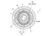
減速機6は、スラスト方向、およびラジアル方向の両方向の荷重を受けることのできるクロスローラベアリング28とハーモニックドライブ(登録商標)とを一体化したものである。すなわち、減速機6は、回転軸5に外嵌固定されているウェーブジェネレータ29と、このウェーブジェネレータ29の外周に配置されたフレクスプライン30とを有し、フレクスプライン30の外周にクロスローラベアリング28を配置してある。そして、クロスローラベアリング28の内輪(インナーレース)28aがハーモニックドライブ(登録商標)のサーキュラスプライン31も兼ねている。One end of the rotating shaft 5 (left end in FIG. 2) protrudes from the
The
ウェーブジェネレータ29は、平面視楕円状のカム32と、この外周に設けられたボールベアリング33とで構成されている。カム32の径方向中央には、回転軸5とカム32とを連結するための軸孔47が形成されており、これによって回転軸5とカム32とが一体となって回転する。 The
ウェーブジェネレータ29のボールベアリング33の外周面に設けられたフレクスプライン30は弾性を有する歯車であって、筒状の歯車本体34と、この歯車本体34の外側端に一体成形された外フランジ部35とで構成されている。
歯車本体34はウェーブジェネレータ29によって楕円状に変形しており、この内周面は、ウェーブジェネレータ29と摺動可能に形成されている。また、歯車本体34の外周面には、歯部36が形成されている。The
The
フレクスプライン30の外フランジ部35には、外周部に肉厚部37が全周に渡って形成されている。この肉厚部37の径方向の幅は、クロスローラベアリング28の外輪(アウターレース)28bの径方向の幅と略一致するように設定されている。また、肉厚部37には複数のボルト孔38が形成されている。このボルト孔38にボルト39が螺入されることによって、外フランジ部35と第二フレーム3とがクロスローラベアリング28の外輪(アウターレース)28bに共締めされた状態になっている。 The
すなわち、クロスローラベアリング28の外輪28bには、フレクスプライン30のボルト孔38に対応する部位に雌ネジ部40が刻設されており、ここにボルト39が螺入されるようになっている。
また、第二フレーム3の電動回転継手1側端であって、フレクスプライン30に対応する部位には、板状の取付けステー41が一体的に設けられている。このステー41のボルト孔38に対応する部位に、ボルト39を螺入するボルト孔42が形成されている。これによって、第二フレーム3、フレクスプライン30、およびクロスローラベアリング28の外輪28bが一体となる。That is, the
Further, a plate-like mounting stay 41 is integrally provided at a portion corresponding to the
クロスローラベアリング28の内輪28aには、内周面側にフレクスプライン30の歯部36と噛合う歯部43が形成されている。フレクスプライン30の歯車本体34はウェーブジェネレータ29によって楕円状に変形しているので、フレクスプライン30の楕円の長軸部分では歯車本体34の歯部36と内輪28aの歯部43、つまり、サーキュラスプライン31とが噛合った状態になっている。一方、フレクスプライン30の楕円の短軸部分では、互いの歯部36,43が完全に離反した状態になる。 The
また、クロスローラベアリング28の内輪28a(サーキュラスプライン31)の歯部43の歯数は、フレクスプライン30に形成されている歯部36の歯数よりも多く設定されている。
さらに、クロスローラベアリング28の内輪28aに複数のボルト孔44が形成されていると共に、第一フレーム2のボルト孔44に対応する部位に雌ネジ部46が刻設されている。これによって、第一フレーム2にクロスローラベアリング28の内輪28aがボルト45によって締結固定されている。Further, the number of teeth of the
Further, a plurality of bolt holes 44 are formed in the
次に、電動回転継手1の動作について説明する。
まず、回転軸5が例えば時計回り(図3における矢印B方向)に回転すると、この回転軸5と一体となって減速機6のウェーブジェネレータ29が回転する。
すると、フレクスプライン30の歯車本体34がウェーブジェネレータ29の回転に追随するように弾性変形し、フレクスプライン30の歯部36とサーキュラスプライン31(内輪28a)の歯部43との噛合い位置が順次移動する。Next, the operation of the electric rotary joint 1 will be described.
First, when the
Then, the gear
このとき、サーキュラスプライン31(クロスローラベアリング28の内輪28a)は、ボルト45によって第一フレーム2に締結固定されていると共に、フレクスプライン30の歯部36の歯数がサーキュラスプライン31の歯部43の歯数よりも少なく設定されているので、フレクスプライン30が反時計回り(図3における矢印C方向)に歯数が少ない分だけ回転する。 At this time, the circular spline 31 (the
すると、フレクスプライン30の外フランジ部35にボルト39によって共締めされている第二フレーム3、およびクロスローラベアリング28の外輪28bがフレクスプライン30と一体になって反時計回りに回転する。これによって、第二フレーム3が第一フレーム2に対して軸線J(図2参照)を中心に回動する。 Then, the
したがって、上述の実施形態によれば、電動モータ4のフロントブラケット7を第一フレーム2と一体成形し、第一フレーム2の一部がフロントブラケット7を兼ねた状態、つつまり、フロントブラケット7と第一フレーム2の一部とを共有した状態にすることができる。このため、電動回転継手1の占有スペースを小さくすることができ、結果的に第一フレーム2と第二フレーム3との連結部分(関節部分)を小型化できると共に、軽量化することができる。 Therefore, according to the above-described embodiment, the
また、電動モータ4の回転軸5が中空状に形成されているので、電動モータ4の質量を低減することができると共に、回転軸5の内部に配線などを配索させることが可能になる。このため、さらに第一フレーム2と第二フレーム3との連結部分を小型化できる。
さらに、回転子11は、回転軸5に外嵌固定されたロータコア24の軸線方向両端面に円環状の凹部27a,27bを形成している。このため、ロータコア24を薄肉形状として回転子11の軽量化を図ることができる。また、リヤブラケット8側の凹部27aに磁気式エンコーダ20を構成するセンサマグネット19を収納できるので、磁気式エンコーダ20を電動モータ4の内部に配置することが可能になり、電動モータ4の扁平化を図ることができる。よって、より第一フレーム2と第二フレーム3との連結部分を小型化できる。Moreover, since the
Further, the
そして、電動モータ4の駆動力を減速機6を介して第二フレーム3に伝達するにあたって、減速機6をクロスローラベアリング28とハーモニックドライブ(登録商標)とで構成している。このため、減速機6を構成する各部品、つまり、クロスローラベアリング28、ウェーブジェネレータ29、フレクスプライン30、およびサーキュラスプライン31を回転軸5の外周側に配置することが可能になる。よって、減速機6を用いても電動回転継手1に軸線方向に貫通する空間を形成することができ、配線(不図示)などの配索経路を妨げるおそれがないので、さらに第一フレーム2と第二フレーム3との連結部分を小型化できる。 When the driving force of the
また、クロスローラベアリング28の内輪28aに歯部43を形成することで、クロスローラベアリング28の内輪28aにサーキュラスプライン31の役割を兼ねさせている。このため、減速機6を小型化することが可能になると共に、軽量化を図ることができる。
さらに、リヤブラケット8を樹脂で形成することで、電動モータ4の軽量化を図ることが可能になる。Further, by forming the
Furthermore, it is possible to reduce the weight of the
なお、本発明は上述の実施形態に限られるものではなく、本発明の趣旨を逸脱しない範囲において、上述の実施形態に種々の変更を加えたものを含む。
また、上述の実施形態では、回転子11のロータコア24に、円環状の凹部27a,27bを形成し、ここに回転子11の回転角度を検出するための磁気式エンコーダ20を構成するセンサマグネット19を収納した場合について説明した。しかしながら、これに限られるものではなく、回転子11の回転角度を検出するセンサとして、磁気式エンコーダ20に代わって光学式エンコーダやレゾルバでもよく、またセンサレスによる駆動でもよい。The present invention is not limited to the above-described embodiment, and includes various modifications made to the above-described embodiment without departing from the spirit of the present invention.
In the above-described embodiment, the
1 電動回転継手
2 第一フレーム(一方のフレーム)
3 第二フレーム(他方のフレーム)
4 電動モータ
5 回転軸
5a 中空部
6 減速機
7 フロントブラケット(ケーシング)
8 リヤブラケット(ケーシング)
9 ケーシング
10 固定子
11 回転子
18 ホール素子
19 センサマグネット
20 磁気式エンコーダ
24 ロータコア(回転子本体)
25 軸孔
26 リングマグネット(永久磁石)
27a,27b 凹部
28 クロスローラベアリング
29 ウェーブジェネレータ
30 フレクスプライン
31 サーキュラスプライン
32 カム
33 ボールベアリング
34 歯車本体
35 外フランジ部
36,43 歯部1 Electric rotary joint 2 First frame (one frame)
3 Second frame (the other frame)
4
8 Rear bracket (casing)
9
25
27a,
Claims (2)
Translated fromJapanese前記電動モータは、ケーシングと、前記ケーシングに固定された固定子と、前記固定子に対して回転自在に設けられ中空状の回転軸を有する回転子とを備え、
前記一方のフレームと前記ケーシングとを一体成形し、
前記他方のフレームを前記減速機を介して前記回転子と連係し、
前記回転子は、略円盤状の回転子本体を有し、
前記回転子本体の外周面に永久磁石を設け、
前記回転子本体の径方向中央に前記回転軸を内嵌固定するための軸孔を形成し、
前記回転子本体の軸線方向両端面であって前記永久磁石と前記軸孔との間に、それぞれ環状の凹部を形成したことを特徴とする電動回転継手。In the electric rotary joint in which one frame and the other frame are rotatably connected via an electric motor and a speed reducer,
The electric motor includes a casing, a stator fixed to the casing, and a rotor having a hollow rotating shaft that is rotatably provided to the stator.
The one frame and the casing are integrally molded,
The other frame is linked to the rotor via the speed reducer,
The rotor has a substantially disc-shaped rotor body,
A permanent magnet is provided on the outer peripheral surface of the rotor body,
Forming a shaft hole for fitting and fixing the rotary shaft in the radial center of the rotor body;
An electric rotary joint characterized in that annular recesses are formed between the permanent magnet and the shaft hole on both axial end faces of the rotor body.
前記回転軸の外周面に取付けられたウェーブジェネレータと、このウェーブジェネレータの外周に配置され前記他方のフレームに取付けられたフレクスプラインと、前記フレクスプラインの外周に配置され前記ケーシングに取付けられたサーキュラスプラインとで構成され、
前記フレクスプラインと前記サーキュラスプラインとが噛合されていることを特徴とする請求項1に記載の電動回転継手。
The speed reducer is
A wave generator attached to the outer peripheral surface of the rotating shaft, a flex spline arranged on the outer periphery of the wave generator and attached to the other frame, and a circular spline arranged on the outer periphery of the flex spline and attached to the casing And consists of
The electric rotary joint according to claim 1, wherein the flex spline and the circular spline are meshed with each other.
Priority Applications (1)
| Application Number | Priority Date | Filing Date | Title |
|---|---|---|---|
| JP2008003324AJP4997121B2 (en) | 2008-01-10 | 2008-01-10 | Electric rotary joint |
Applications Claiming Priority (1)
| Application Number | Priority Date | Filing Date | Title |
|---|---|---|---|
| JP2008003324AJP4997121B2 (en) | 2008-01-10 | 2008-01-10 | Electric rotary joint |
Publications (2)
| Publication Number | Publication Date |
|---|---|
| JP2009160721Atrue JP2009160721A (en) | 2009-07-23 |
| JP4997121B2 JP4997121B2 (en) | 2012-08-08 |
Family
ID=40963910
Family Applications (1)
| Application Number | Title | Priority Date | Filing Date |
|---|---|---|---|
| JP2008003324AExpired - Fee RelatedJP4997121B2 (en) | 2008-01-10 | 2008-01-10 | Electric rotary joint |
Country Status (1)
| Country | Link |
|---|---|
| JP (1) | JP4997121B2 (en) |
Cited By (8)
| Publication number | Priority date | Publication date | Assignee | Title |
|---|---|---|---|---|
| JP2012105483A (en)* | 2010-11-11 | 2012-05-31 | Yaskawa Electric Corp | Rotary electric machine, robot, manufacturing method of the rotary electric machine, and hollow shaft |
| CN102594010A (en)* | 2011-01-11 | 2012-07-18 | 精工爱普生株式会社 | Electric machine device, actuator using the same, motor, robot, and robot hand |
| JP2012171072A (en)* | 2011-02-23 | 2012-09-10 | Yaskawa Electric Corp | Robot, robot system, and rotating electrical machine |
| JP2015061334A (en)* | 2013-09-17 | 2015-03-30 | オリエンタルモーター株式会社 | Linear actuator |
| JP2015080837A (en)* | 2013-10-23 | 2015-04-27 | ヤマハ発動機株式会社 | Industrial robot |
| WO2023108528A1 (en)* | 2021-12-13 | 2023-06-22 | 上海非夕机器人科技有限公司 | Speed reducer, reduction drive system, and robot joint and robot comprising reduction drive system |
| WO2023135688A1 (en)* | 2022-01-12 | 2023-07-20 | 株式会社ハーモニック・ドライブ・システムズ | Machine with hollow portion for electrical wiring |
| WO2023238507A1 (en)* | 2022-06-08 | 2023-12-14 | パナソニックIpマネジメント株式会社 | Magnetic-geared motor and magnetic gear |
Citations (6)
| Publication number | Priority date | Publication date | Assignee | Title |
|---|---|---|---|---|
| JPS61131891A (en)* | 1984-11-29 | 1986-06-19 | 三菱重工業株式会社 | Rotary joint mechanism |
| JPS61214986A (en)* | 1985-03-15 | 1986-09-24 | 株式会社安川電機 | Arm driving mechanism of industrial robot |
| JPH01103276A (en)* | 1987-10-13 | 1989-04-20 | Mitsubishi Electric Corp | Industrial robot |
| JPH0478423A (en)* | 1990-07-19 | 1992-03-12 | Kazuhiro Wada | Separation of mixed components by photoirradiation |
| JPH06315879A (en)* | 1993-02-24 | 1994-11-15 | Fanuc Robotics North America Inc | Electric rotary joint and assembly of modular robot using the same |
| JP2005014098A (en)* | 2003-06-23 | 2005-01-20 | Nachi Fujikoshi Corp | Wrist mechanism of industrial robot |
- 2008
- 2008-01-10JPJP2008003324Apatent/JP4997121B2/ennot_activeExpired - Fee Related
Patent Citations (6)
| Publication number | Priority date | Publication date | Assignee | Title |
|---|---|---|---|---|
| JPS61131891A (en)* | 1984-11-29 | 1986-06-19 | 三菱重工業株式会社 | Rotary joint mechanism |
| JPS61214986A (en)* | 1985-03-15 | 1986-09-24 | 株式会社安川電機 | Arm driving mechanism of industrial robot |
| JPH01103276A (en)* | 1987-10-13 | 1989-04-20 | Mitsubishi Electric Corp | Industrial robot |
| JPH0478423A (en)* | 1990-07-19 | 1992-03-12 | Kazuhiro Wada | Separation of mixed components by photoirradiation |
| JPH06315879A (en)* | 1993-02-24 | 1994-11-15 | Fanuc Robotics North America Inc | Electric rotary joint and assembly of modular robot using the same |
| JP2005014098A (en)* | 2003-06-23 | 2005-01-20 | Nachi Fujikoshi Corp | Wrist mechanism of industrial robot |
Cited By (11)
| Publication number | Priority date | Publication date | Assignee | Title |
|---|---|---|---|---|
| JP2012105483A (en)* | 2010-11-11 | 2012-05-31 | Yaskawa Electric Corp | Rotary electric machine, robot, manufacturing method of the rotary electric machine, and hollow shaft |
| CN102545467A (en)* | 2010-11-11 | 2012-07-04 | 株式会社安川电机 | Rotating machine, robot, method for making the rotating machine, and hollow shaft |
| CN102594010A (en)* | 2011-01-11 | 2012-07-18 | 精工爱普生株式会社 | Electric machine device, actuator using the same, motor, robot, and robot hand |
| JP2012147541A (en)* | 2011-01-11 | 2012-08-02 | Seiko Epson Corp | Electromechanical device, and actuator, motor, robot, and robot hand using the same |
| JP2012171072A (en)* | 2011-02-23 | 2012-09-10 | Yaskawa Electric Corp | Robot, robot system, and rotating electrical machine |
| JP2015061334A (en)* | 2013-09-17 | 2015-03-30 | オリエンタルモーター株式会社 | Linear actuator |
| JP2015080837A (en)* | 2013-10-23 | 2015-04-27 | ヤマハ発動機株式会社 | Industrial robot |
| WO2023108528A1 (en)* | 2021-12-13 | 2023-06-22 | 上海非夕机器人科技有限公司 | Speed reducer, reduction drive system, and robot joint and robot comprising reduction drive system |
| WO2023135688A1 (en)* | 2022-01-12 | 2023-07-20 | 株式会社ハーモニック・ドライブ・システムズ | Machine with hollow portion for electrical wiring |
| JPWO2023135688A1 (en)* | 2022-01-12 | 2023-07-20 | ||
| WO2023238507A1 (en)* | 2022-06-08 | 2023-12-14 | パナソニックIpマネジメント株式会社 | Magnetic-geared motor and magnetic gear |
Also Published As
| Publication number | Publication date |
|---|---|
| JP4997121B2 (en) | 2012-08-08 |
Similar Documents
| Publication | Publication Date | Title |
|---|---|---|
| JP4997121B2 (en) | Electric rotary joint | |
| JP4964303B2 (en) | Motor rotation position detection device | |
| JP5598735B2 (en) | Rotary actuator | |
| US6701803B1 (en) | Reduction gears-integrated actuator | |
| JP6028055B2 (en) | Reducer with motor | |
| CN109661528B (en) | Wave gear speed reducer with motor | |
| JP5197174B2 (en) | Motor with wave reducer | |
| CN109478826B (en) | power unit | |
| WO2019077886A1 (en) | Speed reduction mechanism and motor with speed reducer | |
| JP2007321879A (en) | Reducer unit with rotational position sensor | |
| JP6176219B2 (en) | DRIVE DEVICE AND ELECTRIC POWER STEERING DEVICE | |
| US10465767B2 (en) | Actuator | |
| JP2005138670A (en) | Electric power steering device and assembling method of electric motor | |
| JP5110449B2 (en) | Rotary actuator | |
| JP5467489B2 (en) | Brushless motor and electric power steering apparatus using the same | |
| JP5943802B2 (en) | Hollow wave gear unit | |
| JP2016203707A (en) | Drive unit | |
| US10418867B2 (en) | Switched reluctance motor | |
| US11181178B2 (en) | Strain wave gear speed reducer unit and power unit | |
| JP5448252B2 (en) | Rotating electric machine and robot | |
| JP4701337B2 (en) | Double speed resolver | |
| JP7037619B2 (en) | Strain wave gear reducer unit | |
| JP4940470B2 (en) | Outer rotor type resolver structure | |
| JP2005051969A (en) | Thin actuator | |
| JP2022053024A (en) | Electric actuator |
Legal Events
| Date | Code | Title | Description |
|---|---|---|---|
| A621 | Written request for application examination | Free format text:JAPANESE INTERMEDIATE CODE: A621 Effective date:20101117 | |
| A977 | Report on retrieval | Free format text:JAPANESE INTERMEDIATE CODE: A971007 Effective date:20110705 | |
| A131 | Notification of reasons for refusal | Free format text:JAPANESE INTERMEDIATE CODE: A131 Effective date:20120207 | |
| A521 | Request for written amendment filed | Free format text:JAPANESE INTERMEDIATE CODE: A523 Effective date:20120406 | |
| TRDD | Decision of grant or rejection written | ||
| A01 | Written decision to grant a patent or to grant a registration (utility model) | Free format text:JAPANESE INTERMEDIATE CODE: A01 Effective date:20120508 | |
| A01 | Written decision to grant a patent or to grant a registration (utility model) | Free format text:JAPANESE INTERMEDIATE CODE: A01 | |
| A61 | First payment of annual fees (during grant procedure) | Free format text:JAPANESE INTERMEDIATE CODE: A61 Effective date:20120514 | |
| FPAY | Renewal fee payment (event date is renewal date of database) | Free format text:PAYMENT UNTIL: 20150518 Year of fee payment:3 | |
| R150 | Certificate of patent or registration of utility model | Free format text:JAPANESE INTERMEDIATE CODE: R150 Ref document number:4997121 Country of ref document:JP Free format text:JAPANESE INTERMEDIATE CODE: R150 | |
| LAPS | Cancellation because of no payment of annual fees |