JP2009160384A - Biopsy device with user interface - Google Patents
Biopsy device with user interfaceDownload PDFInfo
- Publication number
- JP2009160384A JP2009160384AJP2008295311AJP2008295311AJP2009160384AJP 2009160384 AJP2009160384 AJP 2009160384AJP 2008295311 AJP2008295311 AJP 2008295311AJP 2008295311 AJP2008295311 AJP 2008295311AJP 2009160384 AJP2009160384 AJP 2009160384A
- Authority
- JP
- Japan
- Prior art keywords
- cutter
- vacuum
- biopsy device
- biopsy
- probe
- Prior art date
- Legal status (The legal status is an assumption and is not a legal conclusion. Google has not performed a legal analysis and makes no representation as to the accuracy of the status listed.)
- Pending
Links
Images


Classifications
- A—HUMAN NECESSITIES
- A61—MEDICAL OR VETERINARY SCIENCE; HYGIENE
- A61B—DIAGNOSIS; SURGERY; IDENTIFICATION
- A61B10/00—Instruments for taking body samples for diagnostic purposes; Other methods or instruments for diagnosis, e.g. for vaccination diagnosis, sex determination or ovulation-period determination; Throat striking implements
- A61B10/02—Instruments for taking cell samples or for biopsy
- A61B10/0233—Pointed or sharp biopsy instruments
- A61B10/0266—Pointed or sharp biopsy instruments means for severing sample
- A61B10/0275—Pointed or sharp biopsy instruments means for severing sample with sample notch, e.g. on the side of inner stylet
- A—HUMAN NECESSITIES
- A61—MEDICAL OR VETERINARY SCIENCE; HYGIENE
- A61B—DIAGNOSIS; SURGERY; IDENTIFICATION
- A61B10/00—Instruments for taking body samples for diagnostic purposes; Other methods or instruments for diagnosis, e.g. for vaccination diagnosis, sex determination or ovulation-period determination; Throat striking implements
- A61B10/02—Instruments for taking cell samples or for biopsy
- A61B10/0233—Pointed or sharp biopsy instruments
- A61B10/0283—Pointed or sharp biopsy instruments with vacuum aspiration, e.g. caused by retractable plunger or by connected syringe
- A—HUMAN NECESSITIES
- A61—MEDICAL OR VETERINARY SCIENCE; HYGIENE
- A61B—DIAGNOSIS; SURGERY; IDENTIFICATION
- A61B10/00—Instruments for taking body samples for diagnostic purposes; Other methods or instruments for diagnosis, e.g. for vaccination diagnosis, sex determination or ovulation-period determination; Throat striking implements
- A61B10/02—Instruments for taking cell samples or for biopsy
- A61B2010/0208—Biopsy devices with actuators, e.g. with triggered spring mechanisms
- A—HUMAN NECESSITIES
- A61—MEDICAL OR VETERINARY SCIENCE; HYGIENE
- A61B—DIAGNOSIS; SURGERY; IDENTIFICATION
- A61B10/00—Instruments for taking body samples for diagnostic purposes; Other methods or instruments for diagnosis, e.g. for vaccination diagnosis, sex determination or ovulation-period determination; Throat striking implements
- A61B10/02—Instruments for taking cell samples or for biopsy
- A61B2010/0225—Instruments for taking cell samples or for biopsy for taking multiple samples
- A—HUMAN NECESSITIES
- A61—MEDICAL OR VETERINARY SCIENCE; HYGIENE
- A61B—DIAGNOSIS; SURGERY; IDENTIFICATION
- A61B17/00—Surgical instruments, devices or methods
- A61B2017/00017—Electrical control of surgical instruments
- A61B2017/00199—Electrical control of surgical instruments with a console, e.g. a control panel with a display
- A—HUMAN NECESSITIES
- A61—MEDICAL OR VETERINARY SCIENCE; HYGIENE
- A61B—DIAGNOSIS; SURGERY; IDENTIFICATION
- A61B17/00—Surgical instruments, devices or methods
- A61B2017/00367—Details of actuation of instruments, e.g. relations between pushing buttons, or the like, and activation of the tool, working tip, or the like
- A61B2017/00398—Details of actuation of instruments, e.g. relations between pushing buttons, or the like, and activation of the tool, working tip, or the like using powered actuators, e.g. stepper motors, solenoids
- A—HUMAN NECESSITIES
- A61—MEDICAL OR VETERINARY SCIENCE; HYGIENE
- A61B—DIAGNOSIS; SURGERY; IDENTIFICATION
- A61B17/00—Surgical instruments, devices or methods
- A61B2017/0046—Surgical instruments, devices or methods with a releasable handle; with handle and operating part separable
Landscapes
- Health & Medical Sciences (AREA)
- Life Sciences & Earth Sciences (AREA)
- Medical Informatics (AREA)
- Engineering & Computer Science (AREA)
- Biomedical Technology (AREA)
- Heart & Thoracic Surgery (AREA)
- Pathology (AREA)
- Molecular Biology (AREA)
- Surgery (AREA)
- Animal Behavior & Ethology (AREA)
- General Health & Medical Sciences (AREA)
- Public Health (AREA)
- Veterinary Medicine (AREA)
- Surgical Instruments (AREA)
Abstract
Description
Translated fromJapanese〔背景〕
生検サンプルは、種々の医療処置で、様々な装置を用いて様々な方法で採取されている。生検装置は、定位誘導下、超音波誘導下、MRI誘導下、または別の方法で用いることができる。単なる例示的な生検装置が、1996年6月18日発行の米国特許第5,526,822号(名称:「軟組織の自動生検および採取のための方法および装置(Method and Apparatus for Automated Biopsy and Collection of Soft Tissue)」)、2000年7月11日発行の米国特許第6,086,544号(名称:「自動外科生検装置用の制御装置(Control Apparatus for an Automated Surgical Biopsy Device)」)、2003年6月12日公開の米国特許出願公開第2003/0109803号(名称:「MRI適合性外科生検装置(MRI Compatible Surgical Biopsy Device)」)、2007年5月24日公開の米国特許出願公開第2007/0118048号(名称:「外科生検装置用の遠隔サムホイール(Remote Thumbwheel for a Surgical Biopsy Device)」)、2006年12月13日出願の米国仮特許出願第60/869,736号(名称:「生検システム(Biopsy System)」)、および2006年12月13日出願の米国仮特許出願第60/874,792号(名称:「生検サンプルの貯蔵(Biopsy Sample Storage)」)に開示されている。これらの米国特許、米国特許出願公開、および米国仮特許出願の各開示は、参照して本明細書に組み入れるものとする。生検サンプルを採取するためにいくつかのシステムおよび方法が作られ使用されているが、本発明の以前に、添付の特許請求の範囲に開示する本発明を考案または使用した者はいないと考えられる。〔background〕
Biopsy samples are taken in a variety of ways using a variety of devices in a variety of medical procedures. The biopsy device can be used under stereotactic guidance, ultrasound guidance, MRI guidance, or otherwise. A mere exemplary biopsy device is disclosed in US Pat. No. 5,526,822 issued Jun. 18, 1996 (name: “Method and Apparatus for Automated Biopsy”). and Collection of Soft Tissue) ”), US Pat. No. 6,086,544 issued July 11, 2000 (name:“ Control Apparatus for an Automated Surgical Biopsy Device ”) ), U.S. Patent Application Publication No. 2003/0109803 (name: "MRI Compatible Surgical Biopsy Device") published on June 12, 2003, U.S. Patent published on May 24, 2007. Published Application No. 2007/0118048 (Name: “Remote Thumbwheel for a Surgical Biopsy Device”), US provisional patent filed on December 13, 2006 No. 60 / 869,736 (name: “Biopsy System”) and US Provisional Patent Application No. 60 / 874,792, filed December 13, 2006 (name: “Biopsy Sample”). Biopsy Sample Storage ”). The disclosures of these US patents, US patent application publications, and US provisional patent applications are hereby incorporated by reference. Although several systems and methods have been made and used to obtain biopsy samples, it is believed that no one has devised or used the present invention disclosed in the accompanying claims prior to the present invention. It is done.
〔詳細な説明〕
本明細書は、本発明を詳細に示し、明確に請求する特許請求の範囲で締めくくるが、本発明は、同様の参照符号が同じ構成要素を示す添付の図面を参照しながら、特定の例の以降の説明からより良く理解できるであろう。[Detailed explanation]
While the specification concludes with the claims particularly pointing and distinctly claiming the invention, the invention is not limited to the specific examples, with reference to the accompanying drawings, wherein like reference numerals designate like elements, and in which: This will be better understood from the following description.
本発明の特定の例についての以降の説明は、本発明の範囲を限定するために用いられるべきではない。本発明の他の例、特徴、態様、実施形態、および利点は、当業者には、本発明を実施するのに最適な形態の1つと考える例示目的の以降の説明から明らかになるであろう。当然のことながら、本発明は、全て本発明から逸脱することなく、他の様々な態様および明らかな態様が可能である。したがって、添付の図面および以降の説明は、例示目的であって、制限目的と解釈すべきではない。 The following description of specific examples of the invention should not be used to limit the scope of the invention. Other examples, features, aspects, embodiments, and advantages of the present invention will become apparent to those skilled in the art from the following description, for purposes of illustration, considered one of the best modes for carrying out the present invention. . It will be appreciated that the present invention is capable of various other and obvious aspects, all without departing from the invention. Accordingly, the accompanying drawings and the following description are for illustrative purposes and are not to be construed as limiting purposes.
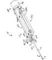
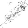
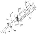
図1に示すように、例示的な生検システム2は、生検装置100、101および真空制御モジュール400を含む。図2および図3に示すように、生検装置100は、プローブ102およびホルスター202を含む。同様に、図4および図5に示すように、生検装置101は、プローブ103およびホルスター302を含む。詳細を後述するように、各プローブ102、103は、対応するホルスター202、302から取り外し可能である。本明細書で用いる用語「ホルスター」は、プローブ102、103のいずれかの部分をホルスター202、302のいずれかの部分の中に挿入する必要があると解釈すべきではない。実際に、生検装置100、101の一部の変更形態では、プローブ102、103は、単にホルスター202、302の上に配置しても良い。ある種の他の変更形態では、ホルスター202、302の一部を、プローブ102、103の中に挿入しても良い。さらに、ある種の生検装置100、101では、プローブ102、103およびホルスター202、302は、これらの2つの構成要素を分離できないように単一体すなわち一体構造にしても良い。プローブ102、103とホルスター202、302との間のさらに他の適当な構造および機能的関係も、当業者であれば、本開示を読めば明らになるであろう。 As shown in FIG. 1, the
生検装置100、101のある種の変更形態は、いつプローブ102、103がホルスター202、302に結合されたかを検出するように構成された1または複数のセンサ(不図示)をプローブ102、103および/またはホルスター202、302内に備えることができる。さらに、このようなセンサまたは他の機能構造は、特定の種類のプローブ102、103とホルスター202、302のみが互いに結合できるように構成しても良い。これに加えてまたは別法では、このようなセンサは、適当なプローブ102、103とホルスター202、302が互いに結合されるまで、プローブ102、103および/またはホルスター202、302の1または複数の機能を無効にするように構成しても良い。もちろん、このようなセンサおよび機能構造は、所望に応じて、変更しても良いし、省いても良い。 Certain modifications of the
単なる例として、プローブ102、103を使い捨て構成要素として用意し、ホルスター202、302を再使用可能な構成要素として用意しても良い。真空制御モジュール400は、本例では、カート(不図示)上に設けられているが、本明細書に記載する他の構成要素と同様に、カートは単なる任意選択である。本明細書に記載する他の構成要素の中で、特に、フットスイッチ(不図示)および/または他の装置を用いて、生検システム2の少なくとも一部の少なくともある程度の制御を行うことができる。導管200により、真空制御モジュール400から生検装置100、101への出力(例えば、電気や空気圧など)、制御信号、生理食塩水、真空、および大気の送達を行うことができる。これらの各構成要素は、詳細を後述する。 By way of example only,
I.定位使用のための例示的なプローブ
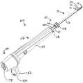
図6〜図14に示すように、プローブ102は、針部分10および本体部分112を備えている。本体部分112は、カバー部材114およびベース部材116を含む。組織サンプルホルダ140が、ベース部材116に取り外し可能に取り付けられているが、この組織サンプルホルダ140は、代替として、カバー部材114または他の構成要素に取り付けても良い。詳細を後述するように、一対のチューブ402、404が、プローブ102に結合されている。I. Exemplary Probe for Stereotactic Use As shown in FIGS. 6-14, the
A.例示的な針
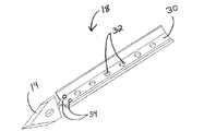
本例では、針部分10は、組織刺入先端部14およびこの組織刺入先端部14の近位側に位置する横方向組織受容口16を有する外側カニューレ12を含む。組織刺入先端部14は、大きな力も、この先端部14の刺入の前に組織に予め開口を形成する必要もなく、組織に刺入できるように構成されている。組織刺入先端部14の適切な構造は、当業者であれば、本開示を読めば明らかになるであろう。例えば、図11に示すように、本例の先端部14は、金属製の打抜き部品の形態である針部品18の一部である。具体的には、針部品18は、詳細を後述するように、打ち抜かれて先端部14および壁30が形成されている。ベント開口34を含む複数の開口32が、壁を貫通して形成されている。開口32、34を介して流体を供給できる様々な方法を、図61〜図65を参照して詳細に後述する。針部品18は、先端部14と壁30が互いに実質的に垂直となるように捩られている。次いで、針部品18をカニューレ12内に挿入して、先端部14がカニューレ12の遠位端部に形成されたスロットから延出するようにする。組織ストッパ26が、先端部14のすぐ近位側に設けられている。代替の技術、材料、および構造を含め、先端部14を形成できるさらに別の方法も、当業者であれば、本開示を読めば明らかになるであろう。A. Exemplary Needle In this example, the
本例の外側カニューレ12の内部には、カニューレ内腔20および真空内腔40が画定されており、壁30が、このカニューレ内腔20と真空内腔40を分離している。複数の外面開口22が、外側カニューレ12に形成されており、これらの外面開口22は、真空内腔40に流体連通している。外面開口22に類似した開口の例が、参照して開示内容を本明細書に組み入れる2007年2月8日公開の米国特許出願公開第2007/0032742号(名称:「真空補助型出血制御機構を備えた生検装置(Biopsy Device with Vacuum Assisted Bleeding Control)」)に開示されている。もちろん、本明細書に記載する他の構成要素と同様に、外面開口22も単なる任意選択である。 A cannula lumen 20 and a
一部の実施形態では、壁30は、針部分10の有意な長さに亘って延びている。他の実施形態では、壁30は、詳細を後述するカッター50の遠位端部が針部分10で終わっている領域を僅かに越えて近位側に延びている。例えば、カニューレ内腔20は、カッター50が内部に配置されると、カッター50の外面とカニューレ12の内面の少なくとも一部との間に間隙が存在する大きさおよび構造にすることができる。このような間隙は、壁30の近位端部の近位側のカニューレ12の長さに沿って真空内腔40を画定することができる。真空内腔40を画定できるさらに他の方法も、当業者であれば、本開示を読めば明らかになるであろう。 In some embodiments, the
本例では、カニューレ内腔20と真空内腔40との間を流体連通させるために複数の横方向開口32、34が壁30を貫通して形成されている。詳細を後述するように、真空、生理食塩水、および/または加圧空気を、真空内腔40から横方向開口32、34を介してカニューレ内腔20に伝えることができる。 In this example, a plurality of
B.例示的なカッター
中空カッター50が、カニューレ内腔20内に配置されている。カッター50の内部は、カッター内腔52を介して流体および組織をカッター50内を移動させることができるようにカッター内腔52を画定している。詳細を後述するように、カッター50は、カニューレ内腔20内で回転し、カニューレ内腔20内を軸方向に移動するように構成されている。具体的には、カッター50は、外側カニューレ12の横方向開口16内に導入された組織から生検サンプルを切除するように構成されている。同様に詳細を後述するように、カッター50は、さらに、切除した組織サンプル4をカッター内腔52を介して近位側に移送できるように構成されている。このような切除および近位側への移送の単なる例示的な例が、参照して開示内容を本明細書に組み入れる米国特許第5,526,822号に開示されているが、生検システム2内で組織サンプル4を切除および/または移送するためにあらゆる他の適当な構造および技術を用いても良い。B. Exemplary Cutter A
カッター50は、カッター内腔52を介した組織サンプル4の近位側への移送を容易にするために様々な処置を施す、または様々な構成にすることができる。例えば、カッター内腔52を画定しているカッター50の内側の表面仕上げは、組織とカッター50との間の付着性を低減するためにショットピーニング(例えば、ガラスビーズや炭酸水素ナトリウムなどを用いる)を行うことができる。加えてまたは別法では、カッター内腔52を画定しているカッター50の内側に、組織とカッター50との間の付着性を低減するために酸エッチングおよび/またはプラズマエッチングを施しても良い。加えてまたは別法では、組織とカッター50との間の摩擦を低減するために、水潤滑性材料(hydrolubricous material)または他の非接着性コーティングを、カッター内腔52を画定しているカッター50の内面に設けても良い。加えてまたは別法では、カッター内腔52を画定しているカッター50の内面に、ライフル表面カット(rifling surface cut)を施しても良い。カッター50の内面の他の適当な処理も、当業者であれば、本開示を読めば明らかになるであろう。あるいは、一部の実施形態では、カッター50の内面に処理を一切施さなくても良い。 The
カッター50の代替の実施形態では、カッター50の遠位部分は、カッター50の近位部分の内径および外径よりも小さい内径および外径を有する。例えば、カッター50の最遠位から1インチ(25.4mm)までの部分が、カッター50の残りの近位方向の長さに沿った大きい直径を有する領域に移行する縮径部(不図示)を形成しても良い。このような縮径構造は、組織サンプル4がカッター内腔52内を近位側に移動する際の組織の圧縮を低減することができる。外側カニューレ12の遠位端部は、カッター50の縮径部と同じ、短い、または長い相補的な縮径部を有しても良い。カッター50および/または外側カニューレ12における縮径部の他の適当な長さも、当業者であれば、本開示を読めば明らかになるであろう。 In an alternative embodiment of
カッター50の別の代替の実施形態では、カッター50の内側に向かって延びた複数の隆起面が、カッター50の長さに沿って形成されている。このような隆起面は、カッター50の内面と接触する組織面を低減するように構成しても良い。 In another alternative embodiment of the
カッター50のさらに別の代替の実施形態では、内側スリーブ(不図示)を、カッター50の遠位端部内側に設けても良い。例えば、このような内側スリーブは、約0.15インチ(約0.381mm)の長さか、任意の他の適当な長さを有することができる。カッター50の遠位端部は、内側スリーブを挿入した後に面取りをして、この面取りされたカッター50の遠位端部と面取りされたスリーブの端部が、全体として組織を切除するための鋭い縁を画定することができる。切除された組織サンプル4は、カッター内腔52内を近位側に移動する際に、内側スリーブの近位端部を通過するとすぐに、カッター内腔52のより大きい内径に遭遇する。この有効内径の増大により、組織サンプル4の圧縮が軽減されるため、組織サンプル4の移送の信頼性が向上する。カッター50の更に他の適当な変更形態も、当業者であれば、本開示を読めば明らかになるであろう。 In yet another alternative embodiment of the
C.例示的な針ハブ
図12および図13に示すように、針ハブ60は、外側カニューレ12に固定されており、サムホイール62、およびこのサムホイール62から近位側に延びたスリーブ部分64を含む。本例の針ハブ60は、外側カニューレ12の近位部分の周りにオーバーモールドされているが、針ハブ60を形成し、かつ/または任意の他の適当な技術(例えば、止めネジや接着剤など)を用いて外側カニューレ12に固定しても良い。さらに、本例の針ハブ60は、プラスチック材料から形成されているが、任意の他の適当な材料または材料の組み合わせを用いても良い。C. Exemplary Needle Hub As shown in FIGS. 12 and 13, the
本例のスリーブ部分64は、環状突出部66、長手方向スロット68、およびスリーブ部分64の近位端部近傍に形成された横方向開口70を含む。1または複数の追加の横方向開口70(例えば、横方向開口70の径方向反対側)をスリーブ部分64に設けても良い。一方のOリング72が横方向開口70の近位側、他方のOリング72が横方向開口70の遠位側に位置するように一対のOリング72が配置されている。詳細を後述するように、横方向開口70は、外側カニューレ12の真空内腔40に流体連通した針ハブ60によって画定された内部に流体連通している。スリーブ部分64の他の適当な構造も、当業者であれば、本開示を読めば明らかになるであろう。 The
サムホイール62は、外側カニューレ12を、カバー部材114およびベース部材116に対してその長手方向軸を中心に回転させるように動作可能である。例えば、サムホイール62を用いて、外側カニューレ12によって画定された長手方向軸を中心に様々な所望の向きに開口16を合わせることができる。このような多数の向きは、単なる例として、複数の組織サンプル4を採取する際に、患者から針部分10を取り外す必要なく、生検部位から複数の組織サンプル4を得るのが望ましいであろう。このような回転および複数の組織サンプル4の採取の例示的な例が、参照して開示内容を本明細書に組み入れる米国特許第5,526,822号に開示されている。様々な位置で複数の組織サンプル4を採取する他の方法も、当業者であれば、本開示を読めば明らかになるであろう。例えば、外側カニューレ12の回転は、詳細を後述する任意の構成要素を用いる、または他の任意の適当な構成要素や技術を用いるなどして電動すなわち自動化しても良い。別の非網羅的な例として、外側カニューレ12によって画定された長手方向軸を中心とする様々な向きから組織サンプル4を採取する際は、このような回転および組織サンプル4の採取の際に患者から生検装置101を取り外さなくとも、組織サンプル4の採取中に生検装置101全体を回転させることができる。 The
他の構造を用いて外側カニューレ12の回転を手作業で行うこともできることを理解されたい。具体的には、図12および図13に示すように、露出した歯車74を外側カニューレ12に係合させることができる。この例では、歯車74は、スリーブ部分64の近位端部上をスライドする。歯車74の径方向内側に延びた突出部(不図示)が、歯車74がスリーブ部分64と一体に回転し、かつスリーブ部分64に沿って長手方向に移動可能であるように、スリーブ部分64のスロット68に適合するように構成されている。スリーブ部分64が外側カニューレ12に一体的に結合された状態で、開口16の向きを合わせるために、歯車74の回転により、カニューレ12を回転させることもできる。歯車74はさらに、詳細を後述するように、ホルスター202の露出した相補的な歯車206と噛合するように構成されている。具体的には、歯車74は、歯車206が歯車74を回転させて外側カニューレ12を回転させるために、歯車206と噛合するように構成されている。歯車206を選択的に回転させるためのある種の例示的な構造および技術は、詳細に後述するが、当業者であれば、本開示を読めば、他の構造および技術も明らかになるであろう。 It should be understood that rotation of the
本開示を読めば、グラフィカルユーザーインターフェイス上に開口16の向きを示すことができることを理解できよう。例えば、1または複数のセンサが、開口16の向きを検出して、表示データをプロセッサに送信するように動作可能である。このプロセッサは、ディスプレイ(例えば、後述するディスプレイ画面702など)と通信して開口16の向きを表示することができる。開口16の向きをユーザーに提示する他の方法も、当業者であれば、本開示から明らかになるであろう。あるいは、開口16の向きをユーザーに示さなくても良い。 After reading this disclosure, it will be appreciated that the orientation of the
D.例示的な針マニホルド
図12に示すように、針マニホルド80が、スリーブ部分64の周りに設けられている。針マニホルド80は、この例では、ベース部材116に固定されている。針マニホルド80は、チューブ402に流体連通しているため、詳細を後述するように、チューブ402が、針マニホルド80に生理食塩水、真空、大気および/または加圧空気などを送達することができる。針マニホルド80はさらに、横方向開口70を介してスリーブ部分64の内部に流体連通している。Oリング72は、詳細を後述する針10の発射の際などにスリーブ部分64が針マニホルド80に対して長手方向に並進する際であっても、スリーブ部分64がその長手方向軸を中心に回転する際であっても、針マニホルド80とスリーブ部分64との間の流体シールを維持するように構成されている。また、シール(不図示)が、スリーブ部分64の近位端部、およびスリーブ部分64とカッター50との間の境界に設けられている。したがって、針マニホルド80、スリーブ部分64、および外側カニューレ12は、チューブ402を介して針マニホルド80に送達される生理食塩水、真空、大気、および/または加圧空気が、横方向開口70を介して真空内腔40に送達されるように構成され、配置されている。もちろん、任意の他の適当な構造または配置を用いて、生理食塩水、真空、大気、および/または加圧空気などをチューブ402から真空内腔40に送達しても良い。D. Exemplary Needle Manifold As shown in FIG. 12, a
E.例示的なカッターの回転/並進機構
本例では、図14に示すように、プローブ102の本体部分112は、外側カニューレ12内でカッター50を回転および並進させることができるカッター回転/並進機構120を含む。カッター回転/並進機構120は、カッター50に単一体となるように固定されたスリーブ122、ナット部材124、および歯車138を含む。本例では、スリーブ122は、カッター50の周りにオーバーモールドされたプラスチックからなるが、任意の他の適当な材料を用いても良く、スリーブ122は、任意の他の適当な構造または技術(例えば、止めネジなど)を用いてカッター50に固定しても良い。ナット部材124は、ベース部材116に固定されており、雌ネジ126を有する。スリーブ122の一部は、ナット部材124の雌ネジ126に螺合するように構成された雄ネジ128を有する。これらのネジ126、128は、スリーブ122がナット部材124に対して回転すると、この回転方向によって決まる長手方向に、スリーブ122がナット部材124に対して並進するように構成されている。単なる例として、これらのネジ126、128は、1インチ(25.4mm)当たり約40〜50ネジ山となるピッチを有するように構成しても良い。このようなネジピッチは、組織を切除するのに望ましいカッター50の並進に対するカッター50の回転の比を決定することができる。あるいは、任意の他のネジピッチを用いても良い。本例では、スリーブ122がカッター50に単一体となるように固定されているため、スリーブ122のナット部材124に対する長手方向の並進により、カッター50が同じ方向に並進する。E. Exemplary Cutter Rotation / Translation Mechanism In this example, as shown in FIG. 14, the
スリーブ122の別の部分は、複数の外側平坦部130を有する。これらの外側平坦部130は、歯車138の相補的な複数の内側平坦部132に係合するように構成されている。歯車138は、スリーブ122およびカッター50と同軸的に配置されている。これらの平坦部130、132は、歯車138の回転によりスリーブ122が回転するように構成されている。本例では、スリーブ122がカッター50に単一体となるように固定されているため、歯車138およびスリーブ122の回転により、カッター50が同じ方向に回転する。平坦部130、132はさらに、スリーブ122が歯車138に対して長手方向に並進できるように構成されている(例えば、スリーブ122と歯車138との間の適合が、このような並進を防止する程緊密ではない)。したがって、歯車138が回転すると、ネジ126、128と平坦部130、132の相対的な構成から、歯車138の回転により、スリーブ122が同時に回転および長手方向に並進し、これによりカッター50が同時に回転および長手方向に並進することを理解されたい。 Another portion of the
本例では、歯車138は、ベース部材116を介して部分的に露出されており、詳細を後述するように、ホルスター202の相補的な露出した歯車208と噛合するように構成されている。具体的には、歯車138は、歯車208が歯車138を回転させて、これによりカッター回転/並進機構120を作動させるべく、歯車208と噛合するように構成されている。詳細を後述するように、歯車208は、ホルスター202内にあるモータ272に接続されている。本例では、歯車138、208およびネジ126、128は、モータ272の一回転で、カッター50が約0.00012インチ(約0.003mm)並進するように構成されている。もちろん、これらの構成要素のいずれかが、モータ272の回転に対するカッター50の並進の任意の他の適当な比となる他の構成を有しても良い。 In this example, the
本開示を読めば、上記したカッター回転/並進機構120は単なる例示であり、別法として、カッター50の並進および/または回転を様々な他の方法で実現できることを理解されたい。例えば、生検プローブ102は、露出した歯車138を備えなくても良いように、モータ(不図示)または他の装置を備えても良い。あるいは、露出した歯車138以外の任意の適当な構造(例えば、ラックなど)を用いて、カッター15を回転および/または並進させるために、ある他の構成要素から運動またはエネルギーを受け取っても良い。さらに、カッター回転/並進機構120は、2つ以上の露出した歯車138(例えば、一方の歯車138が並進運動を受け取り、他方の歯車138が回転運動を受け止めるなど)を設けるように構成しても良い。他の単なる例示的な別法では、カッター50の並進および/または回転を、空気圧アクチュエータ(不図示)、空気圧モータ(不図示)、または様々な他の構成要素によって少なくとも部分的に達成しても良い。さらに、カッター50を並進および/または回転させるために、空気圧構成要素を、他の機械構成要素および/または電気機械構成要素と組み合わせても良いことを理解されたい。 After reading this disclosure, it should be understood that the cutter rotation /
ベース部材116はさらに、内部にカッター50の近位端部が配置されたカッター通路54を含む。カッター50の外面とカッター通路54の遠位端部の内面との間の真空または流体の漏れを防止するために、シール56が、カッター50とカッター通路54の遠位境界部に設けられている。カッター通路54は、生検装置100の使用中にカッター50が並進しても、カッター50の遠位端部がカッター通路54内に残るような大きさである。もちろん、任意の他の適当な構造または構成を用いても良い。 The
F.例示的な「鋭利物削減」変更形態
本例では、針部分10およびカッター50は、生検装置100の1回の使用の後などに、生検プローブ102から取り外しできるように構成されている。具体的には、生検プローブ102の本体部分112のベース部材116は、アーム119によってベース部材116に対して弾性的に移動可能な取り外しタブ118を含む。取り外しタブ118は、初期設定位置にある場合、上記したようにハブ60のスリーブ部分64に係合した歯車74の軸方向の運動を制限することによって針部分10の軸方向の運動を制限するように構成されている。もちろん、たとえ取り外しタブ118が初期設定位置にあったとしても、歯車74とスリーブ部分64との間の係合および構造により、針部分10の発射のためなど、針部分10のある程度の軸方向の運動を可能になっている。しかし、解放ボタン118は、ユーザーなどによって十分に押されると、歯車74がベース部材116の遠位側に移動するためのクリアランスを画定する。言い換えれば、取り外しタブ118が十分に押されると、針ハブ60および歯車74の全てを含む針部分10全体が、生検プローブ102の本体部分112から軸方向遠位側に引っ張られ、これにより針ハブ60および歯車74の全てを含む針部分10全体を、本体部分112から完全に分離することができる。F. Exemplary “Sharp Reduction” Modification In this example, the
本明細書の開示を読めば、針ハブ60および歯車74の全てを含む針部分10全体が、本体部分112から完全に分離されても、カッター50は、本体部分112から延びていることを理解できよう。カッター50は、ユーザーがカッター50を本体部分112に対して単に緩めて本体部分から取り外すことができる。具体的には、ユーザーは、本体部分112から突き出た針10の部分を把持して、カッター50に対して遠位側に引っ張りながら針10を本体部分112に対して回転させる。このようなカッター50の回転および引く力により、ネジ126と128が相互作用し、最終的に、ネジ128が、ネジ126を遠位側に完全に通過することができる。ネジ128がネジ126を遠位側に完全に通過すると、カッター50を軸方向に実質的に拘束する本体部分112の他の構成要素が存在しないため、カッター50を、さらに回転させなくても本体部分112から遠位側に完全に引き抜くことができる。言い換えれば、カッター50を本体部分112に対して十分に回転させてから、カッター50を本体部分112から完全に分離することができる。本開示を読めば、スリーブ122が針マニホルド80内を完全に軸方向に通過できるように、スリーブ122および針マニホルド80を構成できることを理解できよう。歯車138は、スリーブ122およびカッター50の残りの部分が歯車138に対して軸方向に引っ張られる際に所定の位置に実質的に維持することができる。本体部分112からの針部分10とカッター50の取り外しを実現する、可能にする、または容易にする構成要素間の他の適当な関係も、当業者であれば、本開示を読めば明らかになるであろう。 Upon reading the disclosure herein, it will be understood that the
取り外しタブ118および他の構成要素が、本体部分112からの針部分10とカッター50の完全な取り外しを実現および/または可能にするとして説明したが、本開示を読めば、このような取り外しが、様々な他の構造および技術を用いて実現できることを理解できよう。例えば、一部の実施形態では、タブ118または他の機能構造は、結合している時に十分な力で破壊してベース部材116から分離できるように構成されており、針ハブ60および歯車74の全体を含む針部分10全体を取り外すことができる。さらに別の代替の実施形態では、プローブ102は、針部分10および針ハブ60が本体部分112の残りの部分に対して手作業で角度がつけられると、ベース部材116に配置された保持構造が係合解除され、針ハブ60および歯車74の全てを含む針部分10全体を本体部分112から軸方向に取り外すことができるように構成されている。本体部分112からの針部分10およびカッター50の取り外しを実現する、可能にする、または容易にするためのさらに他の構成要素、機能構造、および技術は、当業者であれば、本開示を読めば明らかになるであろう。 Although the
このような取り外しにより、生検装置100に含まれる「鋭利物」の量を低減できることを理解できよう。具体的には、体液に接触した装置の鋭利な構成要素を他の廃棄物の廃棄とは異なる方法で廃棄する必要がある場合(例えば、通常のゴミ箱とは異なる「鋭利物用ゴミ箱」に入れる)、針部分10およびカッター50の本体部分112からの完全な取り外しにより、針部分10およびカッター50を鋭利な廃棄物の処理手順に従って廃棄することができ、本体部分112の残りの部分を鋭利廃棄物として廃棄しないで済む。言い換えれば、単なる例として、生検装置100を使用したら、針部分10およびカッター50は、本体部分112から取り外して「鋭利物用ゴミ箱」に廃棄し、本体部分112の残りの部分は、通常のゴミ箱に廃棄することができる。 It will be appreciated that such removal can reduce the amount of “sharp” contained in the
G.例示的な組織サンプルホルダマニホルド
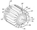
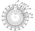
図15〜図19に示すように、組織サンプルホルダ140が、プローブ102の本体部分112の端部に設けられている。組織サンプルホルダ140は、カップ142、マニホルド144、および複数のトレー160を含む。マニホルド144は、中心凹部146、複数の長手方向通路148、径方向に延びた壁152によって画定された複数のチャンバ150、および複数の径方向通路154を含む。各長手方向通路148は、他のすべての長手方向通路148に対して実質的に流体的に分離されている。しかし、各径方向通路154は、マニホルド144の後部内に配置された環状通路(不図示)によって他のすべての径方向通路154と実質的に流体連通している。あるいは、各径方向通路154は、他の全ての径方向通路に対して実質的に流体的に分離しても良い。本例では、各長手方向通路148は、対応する1つの径方向通路154に流体連通している。具体的には、各長手方向通路148は、その近位端部が、対応する径方向通路154まで延びている。G. Exemplary Tissue Sample Holder Manifold As shown in FIGS. 15-19, a
加えて、各径方向通路154は、対応する一対の開口156を介してチャンバ150の対応する1つに流体連通している。したがって、各長手方向通路148は、対応する径方向通路154および一対の開口156を介して対応するチャンバ150に流体連通している。具体的には、各長手方向通路148の中心凹部146に対する径方向位置は、対応する径方向通路154、一対の開口156、およびチャンバ150の径方向位置に一致する。もちろん、任意の他の適当な構造または構成をマニホルド144に用いても良い。 In addition, each
一部の変更形態では、組織が特定の開口または間隙に入る、または通過するのを防止するために、画面、メッシュ、または他の構成要素が、マニホルド144の表面または内部、あるいは組織サンプルホルダ140内の他の部分に設けられている。他の変更形態では、このような構成要素は省かれている。 In some variations, screens, meshes, or other components are placed on the surface or interior of the manifold 144, or the
H.例示的な組織サンプルトレー
本例のトレー160は、マニホルド144上に配置され、詳細を後述するように組織サンプル4を受け取るように構成されている。各トレー160は、硬質とし、概ね弧状の構造を有するように予備成形することができる。あるいは、トレー160は、マニホルド144の曲率に一致しさせるために曲げることができるように、可撓性材料から形成しても良い。あるいは、トレー160は、接合部でトレー160の各部分が曲がるように、1または複数の接合部を備えるようにしても良い。さらに他の適当な構成を用いても良い。H. Exemplary Tissue Sample Tray The
本例の各トレー160は、ベース部分162および複数の中空壁部164を有する。中空壁部164は、チャンバ166を画定している。単なる例として、各チャンバ166は、カッター50によって切除された1つの組織サンプル4を受容するように構成しても良い。あるいは、チャンバ166は、各チャンバ166が2つ以上の組織サンプル4を保持できるように構成しても良い。本例のマニホルド144およびチャンバ166はさらに、組織サンプル4がチャンバ166内にあったとしても、血液、生理食塩水および/または他の流体がこのチャンバ166を通過してチューブ404から出るように構成されている。言い換えれば、チャンバ166は、流体が組織サンプル4の周りを通過するのを可能にしている。 Each
図示するように、各中空壁部164の下面は、マニホルド144の壁152を受容するように構成されている。壁部164および壁152は、トレー160がマニホルド144に配置された時に各ベース部分162とマニホルド144との間に間隙が画定されるように構成されている。同様に図示するように、各中空壁部164は、概ねテーパ構造を有するが、任意の他の適当な構造を用いても良い。加えて、トレー160には、各チャンバ166内のベース部分162を貫通して複数の開口168がセットで形成されている。したがって、トレー160の各チャンバ166は、開口168を介してマニホルド144の対応するチャンバ150に流体連通している。したがって、マニホルド144の各長手方向通路148は、トレー160の対応するチャンバ166に流体連通している。したがって、チューブ404は、所定の長手方向通路148と流体連通するように配置されると、その長手方向通路148に関連するチャンバ166と流体連通することを理解されたい。 As shown, the lower surface of each
本例では、マニホルド144およびトレー160は、18のチャンバ150、166を画定している。あるいは、任意の他の数のチャンバ150、166(すなわち、18未満または19以上)を画定しても良い。例えば、一変更形態では、マニホルド144は、3つのチャンバ150を画定し、それぞれが唯1つのチャンバ166を有する3つのトレー160が用いられる。さらに別の変更形態では、唯1つのトレー160が用いられる。例えば、1つのトレー160は、1つの大きなチャンバ166または任意の適当な数のチャンバ166を画定することができる。他の適当な数のチャンバ150、166、およびこのようなチャンバ150、166を形成する方法は、当業者であれば、本開示を読めば明らかになるであろう。さらに、マニホルド144およびトレー160は、任意の適当な形状を有しても良い。 In this example,
各トレー160はさらに、あるチャンバ166を別のチャンバ166と識別するために1または複数種のマーキングまたは他の印を有しても良い。例えば、凸型または凹型などの数字または他の区別可能なマーキングを各チャンバ166上か、またはその近傍に設けても良い。別の実施形態では、放射線不透過性マーカーが、各チャンバ166上か、またはその近傍に設けられている。例えば、1または複数の組織サンプル4を保持しているトレー160全体を、評価のためにX線下に配置して、各チャンバ166に関連した放射性不透過製マーカー(したがって、各組織サンプル4に関連している)を、X線を用いて取得した画像で視認することができる。言い換えれば、組織サンプル4のX線または放射線画像を撮る際に、組織サンプル4をトレー160から取り外す必要がない。さらに、組織サンプル4がトレー160に保持された状態で、このトレー160を、ホルマリンまたは任意の他の液体に直接入れても良い。加えて、トレー160は、組織サンプル4を保護し、かつ/または組織サンプル4をトレー160に確実に留めるため、または他の目的のために、個別またはまとめてスリーブまたは容器などに入れても良い。このようなスリーブまたは容器は、可撓性、剛性、または他の特性を有しても良い。単なる例として、スリーブまたは他の容器は、平坦にすることができ、内部に挿入される可撓性トレー160を平坦にするように構成しても良い。組織サンプル4がトレー160に移送された後などに、トレー160と共に用いることができる他の構造および技術は、当業者であれば、本開示を読めば明らかになるであろう。 Each
カップ142は、このカップ142をベース部材116に対して十分に回転させた時にベース部材116に対してカップ142を取り外しまたは固定できるように、ベース部材116の差込み部134に係合するように構成されている。加えて、Oリング136が、ベース部材116とカップ142との間にシールを形成するためにベース部材116の周りに設けられている。もちろん、任意の他の適当な構造を用いて、カップ142とベース部材116との結合および/またはベース部材116とカップ142との間のシールを実現しても良い。また、カップ142は、本例では、透明材料から形成されており、組織サンプルホルダ140がベース部材116に結合されている状態で、組織サンプルホルダ140内の組織サンプル4をユーザーが視認することができる。例えば、ユーザーは、色、大きさ、および密度を調べるために組織サンプル4を視認することができる(例えば、チャンバ166が生理食塩水で満たされている場合など)。 The
また、本開示を読めば、カップ142およびトレー160が取り外し可能であるため、比較的短い時間で比較的多数の組織サンプルをユーザーが採取できることを理解できよう。さらに、カップ142およびトレー160が取り外し可能であるため、ユーザーが、不満足な組織サンプル4を組織サンプルホルダ140から取り外し(例えば、ピンセットなどを用いて)、その後別のサンプル採取のためにトレー160およびカップ142を再び結合することができる。本例の組織サンプルホルダ140の取り外し性および他の特性を利用できる他の方法も、当業者であれば、本開示を読めば明らかになるであろう。 Also, after reading this disclosure, it will be appreciated that the user can take a relatively large number of tissue samples in a relatively short time because the
I.マニホルドの例示的な回転および整合
本例のマニホルド144は、詳細を後述するように、ベース部材116に対して回転するように構成されている。本例のマニホルド144はさらに、各長手方向通路148がチューブ404に流体連通したポート406に選択的に整合できるように構成されている。このような長手方向通路148とポート406との整合により、整合した長手方向通路148がチューブ404と流体連通するため、チューブ404内に真空が導入されると、長手方向通路148内、ならびにこの長手方向通路148に関連したチャンバ166内に真空が導入される。加えて、本例のマニホルド144およびトレー160は、各チャンバ166をカッター内腔52と流体連通するように選択的に配置できるように構成されている。したがって、チューブ404内の真空を、ポート406、関連する長手方向通路148、関連する径方向通路154、関連する一対の開口156、関連するチャンバ150、関連するセットの開口168、および関連するチャンバ166を介して、カッター内腔52内に導入できることを理解されたい。もちろん、真空をカッター内腔52内に導入できる様々な他の方法が存在し、任意の他の適当な構造または技術を用いても良い。さらに、内部に導入される真空の代わりまたはこれに加えて、上記した構成要素を介していずれかの方向に、加圧空気、液体(例えば、生理食塩水)、または任意の他の流体を、移送することができる。I. Exemplary Rotation and Alignment of Manifold The
歯車170が本例のマニホルド144に結合されている。具体的には、歯車170は、マニホルド144の中心凹部146内に挿入されたシャフト172を有する。シャフト172は、中心凹部146の平坦部147に係合するように構成された相補的な平坦部174を有する。平坦部174と147の係合により、歯車170、シャフト172、およびマニホルド144が単一体として回転する。あるいは、歯車170およびマニホルド144は、任意の他の適当な構造または関係を有しても良い。しかし、本例の歯車170を用いてマニホルド144を回転させると、チャンバ166とカッター内腔52の選択的な整合が可能になることに加えて、同時に長手方向通路148とポート406の選択的な整合が可能になる。具体的には、詳細を後述するように、歯車170は、この歯車170を歯車210を用いて回転させることができるように、ホルスター202の相補的な歯車210に噛合するように構成されている。この回転を用いて、チャンバ166をカッター内腔52に選択的(例えば、連続的)に整合させて、生検装置100の使用の際に各チャンバ166内に個々の組織サンプル4を連続的に収集することができる。さらに、このような組織サンプル4の収集は、この処置の際に患者に対して針部分10を引き戻したり再挿入したりしなくても行うことができる。 A
J.例示的な「回転防止(parking)」爪
本例の本体部分112はさらに、ベース部材116に固定された係合部材180を含む。図20に示すように、係合部材180は、歯184を有する爪部分182を含む。爪部分182は、歯184が歯車170に噛合するように弾性的に付勢されている。具体的には、爪部分182の歯184の歯車170との噛合により、歯車170の回転が防止される。(したがって、マニホルド144の回転も防止される)。したがって、爪部分182は、この爪部分182が初期設定位置にある場合、マニホルド144の回転を防止するように構成されている。本例では、爪部分182は、生検プローブ102がホルスター202に結合していない時は初期設定位置にある。しかし、生検装置プローブ102がホルスター202に結合されると、ホルスター202のボス212が、爪部分182に係合するように構成されている。具体的には、ホルスター202のボス212は、生検プローブ102がホルスター202に結合されると爪部分182を歯車170から係合解除するように構成されているため、生検プローブ102がホルスター202に結合されると、爪部分182は、歯車170すなわちマニホルド144の回転を防止しない。生検プローブ102がホルスター202から取り外されると、係合部材180の弾性により、爪部分182が初期設定位置に戻るように付勢されるため、爪部分182が、再び歯車170およびマニホルド144の回転を防止する。J. et al. Exemplary “parking” Claw The
製造施設から輸送のためまたは他の状況で生検プローブ102をパッケージングする際に、所定のチャンバ166がカッター内腔52に整合するように組織サンプルホルダ140を構成することができる。爪部分182が、生検プローブ102が初めて使用するためにホルスター202に結合される時までこのような整合を維持するため、生検装置100を制御するために用いられるソフトウエアまたは制御論理は、所定のチャンバ166がカッター内腔52に整合していると「安全に見なす」ことができ、適宜、生検装置100を制御することができる。さらに、生検プローブ102が、組織サンプル4の採集処置の際にホルスター202から取り外されると、生検装置100を制御するために用いられるソフトウエアまたは制御論理が、ソフトウエアがどのチャンバ166が処置の際に使用されているまたは使用されたかをトラッキングする場合、どのチャンバ166がカッター内腔52と最後に整合したかを思い出すことができる。処置を続けるために生検プローブ102がホルスター202に再び結合されると、ソフトウエアまたは制御論理は、ソフトウエアが思い出したチャンバ166に基づいて生検装置100の制御を続けることができる。あるいは、ユーザーが、新しい生検プローブ102がホルスター202に結合されたことを入力することができ、これによりソフトウエアまたは制御論理が、所定のチャンバ166がカッター内腔52に整合したチャンバであると再び「見なす」ことができる。 The
爪部分182は、歯車170およびマニホルド144の回転を選択的に防止する構造として説明してきたが、この目的を果たすために任意の他の代替の構造を用いても良いことを理解されたい。単なる例として、ジュネーブホイール(Geneva wheel)機構(不図示)を、マニホルド144を回転させてこのマニホルド144の回転位置を意図する回転位置間に維持するための代替の機構として用いても良い。例えば、歯車170の代わりとして、ジュネーブ被動ホイール(不図示)を用い、歯車210の代わりとして、ジュネーブ駆動ホイール(不図示)を用いても良い。マニホルド144の回転および/またはマニホルド144の回転位置の維持のための他の適当な別の手段も、当業者であれば、本開示を読めば明らかになるであろう。加えて、生検装置100が、生検プローブ102がホルスター202に結合されていない時にマニホルド144が自由に回転できるように、爪部分182または他の回転防止機構を一切備えないようにしても良いことを理解されたい。 Although the
K.例示的な専用通路
図16、図17、図19、および図21に示すように、本例の組織サンプルホルダ140には、マニホルド144を通る通路158が形成されている。通路158は、マニホルド144を長手方向に完全に貫通して延びており、マニホルド144によって画定された中心軸に対して平行であるが、この中心軸から外れている。チャンバ166と同様に、通路158は、カッター内腔52に選択的に整合するように構成されている。しかし、チャンバ166とは異なり、通路158は、長手方向通路148または径方向通路154のいずれとも流体連通していない。他の変更形態では、通路158は、1または複数の長手方向通路148および/または径方向通路154と流体連通するように形成しても良い。K. Exemplary Dedicated Passage As shown in FIGS. 16, 17, 19, and 21, the
本例の通路158は、器具および/または液体、他の物質などを、マニホルド144およびカッター内腔52を介して送達できるように構成されている。例えば、通路158を用いて、生検部位に1または複数のマーカーを配置するための器具を挿入し、カッター内腔52および外側カニューレ12を経て開口16から延出させることができる。通路158から挿入できる単なる例示的なマーカーアプライヤとして、オハイオ州シンシナティ(Cincinnati, Ohio)に所在のエシコン・エンド・サージェリー社(Ethicon Endo-Surgery, Inc.)が販売するMAMMOMARK生検部位マーカーアプライヤを挙げることができる。通路158から挿入できる他の適当なマーカーアプライヤ装置として、参照して開示内容を本明細書に組み入れる米国特許第7,047,063号、同第6,996,433号、同第6,993,375号、または米国特許出願公開第2005/0228311号に開示されている全ての装置を挙げることができる。変更形態を含むこのようなアプライヤはいずれも、針部分10を患者の体内に挿入した状態で(例えば、生検サンプルを患者から採取した直後など)、通路158内に導入して、開口16を介して1または複数のマーカーを生検部位に配置することができる。このようなマーカーの配置は、生検プローブ102に固定された組織サンプルホルダ140内に組織サンプル4が存在していても行うことができる。あるいは、このようなマーカーアプライヤは、組織サンプルホルダ140が生検プローブ102から取り外された状態で、カッター内腔52内に直接挿入しても良い。 The
上記したように、生検プローブ102は、初めから、初期設定によって所定のチャンバ166がカッター内腔52に整合した状態で用意しても良い。しかし、他の変更形態では、生検プローブ102は、当初、初期設定によって通路158がカッター内腔52に整合した状態で用意しても良い。さらに、ユーザーが、生検装置100の使用中に通路158をカッター内腔52に整合させたい場合、生検装置の使用中にマニホルド144を回転させてから、制御を用いてマニホルド144を回転させる命令を出して、通路158をカッター内腔52に整合させることができる。 As described above, the
カップ142は、開口176およびハッチ178も含む。開口176は、マニホルド144を回転させて通路158を開口176に整合させるなどして、カップ142がベース部材116に固定されている時に通路158に整合されるように構成されている。ハッチ178は、開口176を選択的に覆うように構成されている。例えば、ハッチ178は、開口176を覆う時に開口176を密閉するように構成しても良い。さらに、ハッチ178は、開口176および通路158にアクセスできるようにするために、ユーザーが、ハッチ178を「剥がし」、かつ/またはハッチ178を回転させることができるように構成しても良い。本開示を読めば、限定するものではないが、取り外し可能なストッパーまたは他の構造を含む様々な代替の構造を、ハッチ178の代わりとして、または追加として用いることができることを理解できよう。
L.例示的な薬物アプライヤ
図21および図22に示すように、アプライヤ90を、カップ142の開口176およびマニホルド144の通路158内に通して生検プローブ102に結合することができる。この例では、アプライヤ90は、中空シャフト部分92、およびルアーロック部分94を含む。シャフト部分92は、アプライヤ90が開口176および通路158内に挿入されると、シャフト部分92がカッター内腔52とシールを形成する(例えば、カッター内腔52の内面との係合によって)大きさおよび構造を有する。したがって、シャフト部分92およびルアーロック部分94は、カッター内腔52と流体連通するように配置することができる。単なる例として、シリンジ(不図示)または他の装置をルアーロック部分94に結合しても良い。したがって、治療薬を、シリンジなどからアプライヤ90、カッター内腔52、および外側カニューレ12を介して注入して、開口16から生検部位に送達することができる。このような注入は、生検装置100を用いて組織サンプル4を採取する前後に行うことができ、針部分10が患者の体内に挿入された状態で行うことができる。アプライヤ90を用いることができる他の適当な方法、ならびにアプライヤ90を構成できる代替の方法も、当業者あれば、本開示を読めば明らかになるであろう。単なる例として、アプライヤ90は、別法として、組織サンプルホルダ140が生検プローブ102から取り外された状態でカッター内腔52内に直接挿入しても良い。L. Exemplary Drug Applier As shown in FIGS. 21 and 22, the
II.定位使用のための例示的なホルスター
図23〜図32に示すように、ホルスター202は、各歯車206、208、210の一部を露出させている上部カバー204、側面パネル214、216、およびベース部材218を含む。上記したように、ボス212は、上部カバー204に設けられており、生検プローブ102がホルスター202に結合されると、爪部分182を歯車170から係合解除するように構成されている。この例のホルスター202は、針回転機構220、針発射機構240、カッター駆動機構270、および組織ホルダ回転機構280も含む。加えて、ユーザーインターフェイス800が、各側面パネル214、216に設けられている。これらの単なる例示的な各構成要素の詳細は後述する。II. Exemplary Holster for Stereotaxic Use As shown in FIGS. 23-32, the
上記したように、本例のホルスター202は、上記した生検プローブ102などの生検プローブ102に結合されて生検装置100を形成するように構成されている。加えて、ホルスター202は、定位設定またはX線設定に用いるなどのために台、固定具、または他の装置に取り付けるように構成されている。しかし、本開示を読めば、ホルスター202を様々な他の設定および組み合わせに用いても良いことを理解できよう。 As described above, the
A.例示的な針回転機構
本例では、図27に示すように、針回転機構220は、細長いシャフト228の近位端部に設けられた歯車226とベベル噛合(beveled engagement)した歯車224をそれぞれ有する一対のノブ222を含む。シャフト228の遠位端部に設けられた別の歯車(不図示)が、歯車230に噛合している。歯車230は、別のシャフト234の近位端部に設けられた別の歯車232に噛合している。シャフト234の遠位端部は、上記した歯車206に噛合した別の歯車236を有する。したがって、本開示を読めば、ノブ222の一方または両方が回転すると、この回転が歯車224、226、230、236およびシャフト228、234を介して伝達されて歯車206が回転することを理解できよう。さらに、上記したように、生検プローブ102がホルスター202に結合されると、歯車206が歯車74に噛合する。したがって、生検プローブ102がホルスター202に結合されると、ノブ222の一方または両方の回転により、生検プローブ102の針部分が回転する。もちろん、様々な代替の機構、構造、または構成を、針回転機構222の代替または追加として用いても良い。単なる例として、モータ(不図示)を用いて針部分10を回転させても良い。他の変更形態では、針回転機構220全体を単に省いても良い。A. Exemplary Needle Rotation Mechanism In this example, as shown in FIG. 27, the
B.例示的な針発射機構
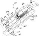
図28および図29に示すように、本例の針発射機構240は、一対のトリガー242、ボタン244、モータ246、発射ロッド248、およびフォーク250を含む。フォーク250は、生検プローブ102がホルスター202に結合されると針ハブ60のスリーブ部分64に係合するように構成されている。例えば、フォーク250は、サムホイール62と環状突出部66との間のスリーブ部分64に係合することができる。本例では、フォーク250とスリーブ部分64との間の係合により、スリーブ部分64(したがって、針部分10)がフォーク250と共に長手方向に並進する。フォーク250は、このフォーク250が発射ロッド248と共に長手方向に並進できるように発射ロッド248に結合されている。B. Exemplary Needle Firing Mechanism As shown in FIGS. 28 and 29, the
ワッシャー253を備えたダンパー252が、発射ロッド248の周りに設けられている。コイルバネ254も、発射ロッド248の周りに設けられている。具体的には、コイルバネ254は、ワッシャー253およびベース部材218の一部の両方に係合している。コイルバネ254は、ダンパー252、ワッシャー253、および発射ロッド248を遠位側に押すように付勢されている。しかし、上記した他の構成要素と同様に、コイルバネ254は単なる例示であり、様々な代替の構成要素(弾性または別の特性を有する)を、コイルバネ254の追加または代わりとして用いても良いことを理解されたい。 A
また、スレッド256およびネジ歯車258が、発射ロッド248に結合されている。具体的には、スレッド256は、発射ロッド248の近位端部に結合されており、発射ロッド248と単一体として長手方向に移動するように構成されている。同様に、ネジ歯車258は、発射ロッド248と共に長手方向に並進するが(少なくとも一定範囲の運動によって)、発射ロッド248を中心に回転しないように構成されている。外側歯車260は、ネジ歯車258に噛合している。具体的には、外側歯車260の内側(不図示)がネジ歯車258のネジ山に噛合していて、外側歯車260がネジ歯車258に対して回転すると、この回転によりネジ歯車258が外側歯車260に対して長手方向に並進する。外側歯車260はまた、モータ246に結合された歯車264に噛合した別の歯車262に噛合している。したがって、モータ246が作動して回転すると、この回転によりネジ歯車258、発射ロッド248、およびスレッド256が長手方向に並進する。言い換えれば、モータ246の回転が、歯車262、264を介して外側歯車260に伝達され、この回転が、外側歯車260とネジ歯車258の構成および噛合によって長手方向の運動に変換される。もちろん、これらの全ての構成要素は単なる例示であり、発射ロッド248を長手方向に並進させるために任意の他の適当な構成要素、構成、または技術を用いても良い。 A
本例の各トリガー242は、前方および後方に部分的に回転するように構成されており、ボタン244は、内側に押されるように構成されている。加えて、トリガー242が前方または後方に動かされた時および/またはボタン244が押下された時に、複数のスイッチ(不図示)が、ユーザーによって選択的に作動されるように、これらのスイッチを、トリガー242および/またはボタン244に連動可能に結合しても良い。各トリガー242を中心方向または実質的に垂直方向に付勢するために1または複数の弾性部材(例えば、バネなど)を含めても良い。また、各ボタン244を外側位置に付勢するために1または複数の弾性部材(例えば、バネなど)を含めても良い。また、トリガー242およびボタン244は、本例では、ホルスター202内に流体が流入するのを防止するために密閉されているが、これも、他の機能構造と同様に単なる任意選択である。 Each
本例では、トリガー242は、一方または両方のトリガー242が後方に移動すると、この運動によりモータ246に接続されたスイッチが作動するように構成されている。このような作動によりモータ246が回転し、これにより発射ロッド248が上記したように長手方向近位側に並進する。詳細を後述するように、このようなトリガー242の後方への運動により、モータ246が、針発射機構240の準備すなわち「発射準備(cock)」をすることができる。 In this example, the
本例の針発射機構240は、スレッド256に選択的に係合するように構成されたキャッチ266も含む。具体的には、発射ロッド248およびスレッド256が長手方向近位側に並進すると(例えば、モータ246の回転によって)、スレッド256がキャッチ266に接近する。キャッチ266とスレッド256が係合すると、キャッチ266は、スレッド256(したがって、発射ロッド248)を所定の位置に保持するように構成されている。キャッチ266は、モータ246が回転を停止しても、そしてバネ254がスレッド256および発射ロッド248を遠位位置に向かって付勢しても、スレッドのこのような位置を維持することができる。これらの構成要素が、これらの近位位置および構成にある場合、針発射機構240は、「発射準備」構造にあると言うことができる。針発射機構240の単なる例示的な向きが合わせられた構造が図29に示されている。 The
本開示を読めば、針発射機構240がこのような発射準備構造にあると、フォーク250および針部分10が近位側の発射準備位置に来ることを理解できよう。生検装置100の1または複数の構成要素は、針発射機構240が完全に発射準備されていることを示す音および/または視覚的な表示を提供するように構成しても良い。例えば、生検装置100は、区別できるクリック音、ビープ、または他の音響信号を生成することができ、かつ/またはグラフィカルユーザーインターフェイスが、針発射機構240が発射準備されていることを視覚的に表示することができる。 It will be appreciated from reading this disclosure that when the
加えて、ホルスター202は、針発射機構がいつ発射準備されたか、および/または針発射機構240がいつ発射されたかを感知すなわち検出するように構成された1または複数のセンサ(不図示)または他の機能構造も含むことができる。例えば、成形システム2は、針発射機構240が発射準備されている間は、針発射機構240が発射されるまで1または複数の生検システム2の機能が実質的に利用できないように構成しても良い。単なる例として、生検システム2は、針発射機構240が発射準備の状態にある間は、「サンプル採取」サイクル(後述)の開始、「プローブ内不要物除去」サイクル(後述)の開始、または他の機能を防止することができる。このような機能は、針発射機構240が発射されて、針10が完全に発射された位置に達したら、再び利用可能にすることができる。あるいは、針発射機構240の発射準備は、生検システム2の1または複数の機能に対して全く影響を与えないか、または他の影響を与えるようにしても良い。 In addition, the
一変更形態では、スレッド256が移動してキャッチ266に係合し、針発射機構240が発射準備されると、モータ246が、逆回転することができる。この変更形態では、発射ロッド248の近位部分は、この発射ロッド248を横方向に通るか、またはこの発射ロッド248内に形成された長手方向スロットまたは凹部(不図示)を有しても良い。ネジ歯車258は、発射ロッド248のこのようなスロットまたは他の機能構造に係合するように構成された内側ピンまたは他の機能構造(不図示)を有しても良い。内側ピンまたは他の機能構造は、さらに、ネジ歯車258が発射ロッド248を中心に回転することを防止し、かつ発射ロッド248に対する所定範囲の運動によるネジ歯車258の並進を可能にするように構成されている。例えば、針発射機構240が発射準備される前に、ネジ歯車258のこのようなピンまたは他の機能構造を、発射ロッド248の長手方向スロットまたは凹部の近位端部か、またはその近傍に配置して、モータ246が作動されてネジ歯車258が近位側に移動され、針発射機構240が発射準備されると、ピンまたは他の機能構造が発射ロッド248に係合して、発射ロッド248がネジ歯車258と共に近位側に付勢されるようにすることができる。次いで、スレッド256が近位側に移動してキャッチ266に係合すると、モータ246が逆回転することができる。モータ246のこのような逆回転により、ネジ歯車258が遠位側に並進することができる。発射ロッド248のスロットまたは他の機能構造の構成、およびネジ歯車258のピンまたは他の機能構造の構成により、ネジ歯車258の発射ロッド248に対するこのような遠位側への並進が可能となり、発射ロッドを近位側の発射準備位置に維持することが可能である。さらに、針部分10が、後述するように発射されると、発射ロッド248のスロットまたは他の機能構造の構成、およびネジ歯車258のピンまたは他の機能構造の構成により、このような発射の際に、発射ロッド248がネジ歯車258に対して比較的容易に遠位側に並進することが可能である。限定するものではないが、後述する変更形態を含め、発射ロッド248とネジ歯車258との間の他の適当な関係を用いても良い。 In one variation, when the
ユーザーは、針部分10の準備が完了したら、一方または両方のトリガー242を前方に押して保持し、一方または両方のトリガー242が前方に保持された状態で、一方または両方のボタン244を押すことができる。トリガー242およびボタン244のこのような作動により、キャッチ266がスレッド256を解放することができる。キャッチ266がスレッド256を解放するようにトリガー242およびボタン244を作動させるために用いることができる適当な構造および構成は、当業者であれば、本開示を読めば明らかになるであろう。スレッド256がこのように解放されている状態で、バネ254の弾性により、ダンパー252およびワッシャー253(したがって、発射ロッド248、フォーク250、および針部分10)が遠位側に付勢されて針部分10が発射される。針部分10のこのような遠位側への運動は、比較的突発的にすることができ、針部分10の先端部14で組織を刺入するのに十分な力で行うことができる。 Once the
別の変更形態では、モータ246は、針部分10が発射される前に、逆回転してネジ歯車258を前進させて遠位部分に戻すことはない。例えば、ネジ歯車258は、発射ロッド248に単一体となるように固定することができ、発射ロッド248に対するあらゆる範囲の運動によっても、長手方向のいずれの方向にも並進することができない。この変更形態では、針部分10が発射されると、歯車260、262、264が、自由に回転できるため、発射ロッド248の遠位側への運動に対する抵抗は極僅かである。あるいは、針部分10の発射の際に1または複数の歯車260、262、264の係合を解除するためにラッチ機構(不図示)を設けても良い。針発射機構240を構成または作動させることができる別の方法も、当業者であれば、本開示を読めば明らかになるであろう。 In another variation, the
本例では、トリガー242およびボタン244は、トリガー242が前方に保持されていなければ、ボタン244を押下すなわち作動させても発射しないように構成されている。同様に、トリガー242が前方に保持された状態でボタン244が押下されるまでは、トリガー242の保持により針部分10が発射されない。トリガー242とボタン244のこのような総合依存を実現するための適当な構造および構成は、当業者には明らかであろう。例えば、ボタン244は、トリガー242と共に前方に回転するようにトリガー242と共に回転することができる。このような変更形態では、ボタン244およびキャッチ266は、ボタン244が前方に回転しなければ、ボタン244の作動によりキャッチ266がスレッド256を解放しないように構成しても良い。ボタン244がトリガー242と共に回転するのに加えて、または別法では、トリガー242は、ボタン244が作動された時にトリガー242の前方への回転によりキャッチ266を解放できるように、トリガー242が前方に回転するまでキャッチ266を所定の位置に固定する(例えば、ボタン244が作動された場合でも)ように構成しても良い。発射(または他の目的)のために互いに依存するようにトリガー242とボタン244を構成できる他の方法も、当業者であれば、本開示を読めば明らかになるであろう。 In this example, the
C.例示的なカッター駆動機構
図30に示すように、本例のカッター駆動機構270は、シャフト274が延出したモータ272を含む。歯車208が、シャフト274に取り付けられており、この歯車208は、シャフト274と一体的に回転するように構成されている。上記したように、生検プローブ102がホルスター202に結合されると、歯車208がカッター回転/並進機構120の歯車138と噛合するように、歯車208の一部が、上部カバー204を介して露出されている。したがって、モータ272が作動して回転すると、この回転が、シャフト274および歯車208、138を介して伝達され、上記したようにカッター50が同時に回転および並進する。カッター駆動機構270を構成または動作させる他の方法も、当業者であれば、本開示を読めば明らかになるであろう。C. Exemplary Cutter Drive Mechanism As shown in FIG. 30, the
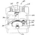
D.例示的な組織ホルダ回転機構
図31および図32に示すように、本例の組織ホルダ回転機構280は、単一体として回転するように歯車286が取り付けられたシャフト284を有するモータ282を含む。歯車286は、シャフト290に取り付けられた歯車288と噛合するように構成されている。また、上記した歯車210も、シャフト290の近位端部に取り付けられている。具体的には、歯車210は、生検プローブ102がホルスター202に結合されると、組織サンプルホルダ140の歯車170と噛合するように構成されている。したがって、モータ282が作動されて回転すると、上記したように、この回転が、シャフト284、290および歯車286、288、210、170を介して伝達されてマニホルド144が回転する。D. Exemplary Tissue Holder Rotation Mechanism As shown in FIGS. 31 and 32, the tissue
加えて、エンコーダホイール292が、シャフト290に結合されており、このエンコーダホイール292は、シャフト290と単一体として回転するように構成されている。エンコーダホイール292は、複数のスロット294が形成されている。これらのスロット294は、径方向外側に向かって広がっており、互いに対して環状に離間している。もちろん、スロット294は、任意の他の適当な構造を有しても良い。センサ296が、エンコーダホイール292に近接して配置されている。具体的には、センサ296は、エンコーダホイール292がシャフト290と共に回転する際にスロット294がセンサ296の前を連続的に通過するように配置されている。したがって、センサ296を用いてスロット294の通過をカウントし、これを、マニホルド144の回転位置を示すデータに変換することができる。言い換えれば、本例では、生検プローブ102がホルスター202に結合されるとエンコーダホイール292とマニホルド144が同時に回転するため、シャフト290の回転の際にセンサ296に対するスロット294の通過が、マニホルド144の回転、したがってマニホルド144の位置を示すことができる。マニホルド144の位置を示す情報は、どのチャンバ166がカッター内腔52に整合しているかを示すこともできることを理解されたい。このような情報の適切な使用法は、当業者であれば、本開示を読めば明らかになるであろう。 In addition, an
センサ296に用いることができる適当な装置は、当業者であれば、本開示を読めば明らかになるであろう。同様に、限定するものではないが、磁石とホール効果センサ、光源、およびフォトセンサなどの組み合わせを含め、エンコーダホイール292およびセンサ296の適当な代替物も、当業者であれば、本開示を読めば明らかになるであろう。さらに、組織ホルダ回転機構280を構成または動作させることができる他の方法も、当業者であれば、本開示を読めば明らかであろう。 Suitable devices that can be used for
III.例示的な超音波用プローブ
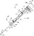
図33〜図37に示すように、代替の生検プローブ103は、針部分350および本体部分352を含む。本体部分352は、カバー部材354およびベース部材356を含む。組織サンプルホルダ368が、ベース部材356に取り外し可能に取り付けられているが、この組織サンプルホルダ368は、代替として、カバー部材354または他の構成要素に取り付けても良い。詳細を後述するように、一対のチューブ402、404が、プローブ103に結合されている。同様に詳細を後述し、上記したように、生検プローブ103は、生検装置101を構成するためにホルスター302に結合するように構成されている。III. Exemplary Ultrasound Probe As shown in FIGS. 33-37, an
A.例示的な針
本例では、針部分350は、組織刺入先端部14およびこの組織刺入先端部14から近位側に配置された横方向組織受容開口16を有する外側カニューレ12を含む。この例では、これらの構成要素は、上記した同じ名称および同じ参照番号を有する構成要素と実質的に同じであるため、詳細は後述しない。言い換えれば、上記した外側カニューレ12、先端部14、および開口16の特徴、特性、および構成要素(カニューレ内腔20、真空内腔40、壁30、横方向開口32などを含む)は、針部分10を用いて説明したように、針部分350と同じにしても良い。もちろん、これらは、所望に応じて、任意の適当な方法で別法として変更しても良い。A. Exemplary Needle In this example, the
同様に、プローブ103のカッター50は、カッター50と針部分10との間の上記した関係と同じ針部分350との間の関係、ならびにプローブ102との関連で記載したカッター50と同じ特徴、特性、および構成要素を有することができる。したがって、このようなカッター50の態様は、ここでは繰り返し説明しない。 Similarly, the
B.例示的な針ハブ
図36および図37に示すように、針ハブ358が、プローブ103の外側カニューレ12に固定されており、この針ハブ358は、サムホイール62およびこのサムホイール62から近位側に延びたスリーブ部分360を含む。本例の針ハブ358は、外側カニューレ12の近位部分の周りにオーバーモールドされているが、針ハブ358を形成し、かつ/または任意の他の適当な技術(例えば、留めネジなど)を用いて外側カニューレ12に固定しても良い。さらに、本例の針ハブ358は、プラスチック材料から形成されているが、任意の他の適当な材料または材料の組み合わせを用いても良い。B. Exemplary Needle Hub As shown in FIGS. 36 and 37, a
本例のスリーブ部分360は、環状突出部66、複数の平坦部362、およびスリーブ部分360の近位端部近傍に形成された横方向開口70を含む。一方のOリング72が、横方向開口70の近位側に位置し、他方のOリング72が、横方向開口70の遠位側に位置するように一対のOリング72が配置されている。詳細を後述するように、横方向開口70は、針ハブ60によって画定された内部ならびに外側カニューレ12の真空内腔40に流体連通している。本例では、別の横方向開口70が、スリーブ部分360を通り、Oリング72の間に形成され、もう一方の横方向開口70の反対側に位置している。スリーブ部分360の他の適当な構成も、当業者であれば、本開示を読めば明らかになるであろう。 The
スリーブ部分360のサムホイール62は、上記したプローブ102のスリーブ部分64のサムホイール62と実質的に同じであり、同様の要領で動作することができる。したがって、サムホイール62は、さらなる詳細を後述しない。もちろん、サムホイール62は、プローブ102または103のいずれかの場合、全て省かなくとも、所望に応じて、任意の適当な方法で別法として変更しても良い。 The
本例では、露出された歯車364が、スリーブ部分360上をスライドする。具体的には、歯車364の内側が、歯車364がスリーブ部分360と単一体として回転するようにスリーブ部分360の平坦部362と適合するように構成されている。スリーブ部分360が、外側カニューレ12と一体的に結合された状態では、歯車364の回転により、開口16の向きを合わせるためにカニューレ12を回転させることができる。歯車364は、ベース部材356を介して露出されており、ホルスター(不図示)の露出された相補的な歯車(不図示)と噛合するように構成されている。具体的には、歯車364は、相補的な歯車が歯車364を回転させて外側カニューレ12を回転させるようにこの相補的な歯車に噛合するように構成されている。しかし、本例では、歯車364は、プローブ103がホルスター302に結合されても相補的な歯車に噛合しない。したがって、上記した他の構成要素および機能構造と同様に、歯車364および平坦部362は、所望に応じて単に省くことができることを理解されたい。 In this example, the exposed
C.例示的な針マニホルド
図34〜図36に示すように、針マニホルド366が、スリーブ部分360の周りに設けられている。針マニホルド366は、この例では、ベース部材356に固定されている。針マニホルド366は、詳細を後述するように、チューブ402が、生理食塩水、真空、および/または加圧空気などを針マニホルド366に送達できるようにチューブ402に流体連通している。針マニホルド366はさらに、横方向開口70(その1つが図37に示されている)を介してスリーブ部分360の内部に流体連通している。Oリング64は、たとえスリーブ部分360が針マニホルド366に対して回転しても、針マニホルド366とスリーブ部分360との間の流体シールを維持するように構成されている。また、シール(不図示)を、スリーブ部分360とカッター50との間の境界面におけるスリーブ部分360の近位端部に設けても良い。したがって、針マニホルド366、スリーブ部分360、および外側カニューレ12は、チューブ402を介して針マニホルド366に送達される生理食塩水、真空、および/または加圧空気などが、横方向開口70を介して真空内腔40に伝達されるように構成および配置されている。もちろん、任意の他の適当な構造または構成を用いて、生理食塩水、真空、および/または加圧空気などをチューブ402から真空内腔40に送達しても良い。C. Exemplary Needle Manifold As shown in FIGS. 34-36, a
D.例示的なカッター回転/並進機構
本例では、図34および図35に示すように、プローブ103の本体部分350は、外側カニューレ12内でカッター50を回転および並進させることができるカッター回転/並進機構120を含む。この例のカッター回転/並進機構120は、プローブ102に関連して説明したカッター回転/並進機構120と実質的に同じ構成要素、機能構造、および操作性を有する。したがって、カッター回転/並進機構120は、さらなる詳細を後述しない。もちろん、カッター回転/並進機構120は、プローブ102または103のいずれかの場合、所望に応じて、別法として任意の適当な方法で変更しても良い。D. Exemplary Cutter Rotation / Translation Mechanism In this example, as shown in FIGS. 34 and 35, the
E.例示的な「鋭利物削減」変更形態
加えて、生検プローブ103の針部分350およびカッター50は、針部分10の生検プローブ102からの取り外しについての記載と実質的に同じ要領で生検プローブ103から取り外しできるように構成しても良い。例えば、本体部分352は、針部分350およびカッター50の本体部分352からの取り外しを実現する、可能にする、または容易にする取り外しタブ118に類似した機能構造または任意の他の適当な機能構造を備えても良い。E. Exemplary “Sharp Reduction” Modification In addition, the
F.例示的な組織サンプルホルダマニホルド
図38〜図40に示すように、組織サンプルホルダ368が、プローブ103の本体部分352の端部に設けられている。組織サンプルホルダ368は、カップ142、マニホルド370、および複数のトレー372を含む。マニホルド370は、中心凹部146、複数の開口374、および長手方向に延びた側壁382を含む。側壁382は、この例では、マニホルド370の長さの一部分のみに亘って延在するが、別法では、所望に応じて任意の他の程度まで延在しても良い。マニホルド370は、複数の径方向に延びた壁380も含む。壁380、および側壁382の内面は、複数の長手方向通路376を画定している。各細長い通路376は、対応する開口374に流体連通している。F. Exemplary Tissue Sample Holder Manifold As shown in FIGS. 38-40, a
加えて、壁380、および側壁382の外面は、複数のチャンバ378を画定している。側壁382がクリアランスを形成しているため(例えば、マニホルド370の全長に亘って延在しないことによって)、各チャンバ378は、対応する長手方向通路376に流体連通している。したがって、マニホルド370は、各開口374が対応するチャンバ378に流体連通するように構成されている。もちろん、マニホルド370に対して任意の他の適当な構造または構成を用いても良い。例えば、生検プローブ102に関連して上記したマニホルド144は、生検プローブ103と共に用いられるマニホルド370の代わりとして生検プローブ103に用いても良い。同様に、マニホルド370は、生検プローブ102に用いられるマニホルド144の代わりとして生検プローブ102に用いても良い。 In addition, the
G.例示的な組織サンプルトレー
本例のトレー372は、マニホルド370上に配置され、詳細を後述するように組織サンプル4を受容するように構成されている。各トレー372は、複数のベース部分382、複数の中空壁部384、および複数のウェブ386を有する。ベース部分382、中空壁部384、およびウェブ386は、チャンバ388を画定している。単なる例として、各チャンバ388は、カッター50によって採取された1つの組織サンプル4を受容するように構成しても良い。あるいは、チャンバ388は、各チャンバ388が2つ以上の組織サンプル4を保持できるように構成しても良い。図示するように、各中空壁部384の下面は、マニホルド370の壁380を受容するように構成されている。同様に図示するように、各中空壁部384は、概ねテーパ状の構造を有するが、任意の他の適当な構造を用いても良い。G. Exemplary Tissue Sample Tray The
加えて、トレー372は、各チャンバ388内のベース部分392を通るように形成された長手方向に延びた複数の開口390を有する。開口390は、各ウェブ386の一部に通って径方向外側に延びている。したがって、側壁382がマニホルド370の全長に亘って延びていない場合は、開口390により、各長手方向通路376と、対応する各チャンバ388との間の流体連通が可能となる。言い換えれば、各開口374は、対応するチャンバ388に流体連通している。 In addition, the
各トレー372は、さらに、あるチャンバ388を別のチャンバ388から区別するために1または複数種のマーキングまたは他の印を含んでも良い。このようなマーキングまたは印は、トレー160のチャンバ166に関連した説明したものと同様にしても良い。したがって、このようなマーキングまたは印の記載は、繰り返し行わない。同様に、組織サンプルホルダ368のカップ142も、上記した組織サンプルホルダ140のカップ142と実質的に同じである。したがって、カップ142の記載も繰り返さない。 Each
H.例示的なマニホルドの回転および整合
本例のマニホルド370は、詳細を後述するように、ベース部材356に対して回転するように構成されている。本例のマニホルド370はさらに、各開口374がチューブ404に流体連通したポート(不図示)と選択的に整合できるように構成されている。開口374とこのポートのこのような整合により、整合した開口374がチューブ404に流体連通するため、チューブ404内へ真空が導入され、これにより開口374ならびにこの開口374に関連したチャンバ388内へ真空が導入される。加えて、本例のマニホルド370およびトレー372は、各チャンバ388がカッター内腔52に選択的に流体連通できるように構成されている。したがって、チューブ406内の真空が、上記したポート、関連する開口374、関連する長手方向通路376、および関連するチャンバ388を介してカッター内腔52に真空を導入することができることを理解されたい。もちろん、カッター内腔52内に真空を導入できる様々な他の方法が存在し、任意の他の適当な構造または技術を用いても良い。さらに、真空を導入する代わり、またはこれに加えて、上記した構成要素を介して、加圧空気、液体(例えば、生理食塩水)、または任意の他の流体を送達することができる。H. Exemplary Manifold Rotation and Alignment The
歯車170が、本例のマニホルド370に係合している。具体的には、歯車170は、マニホルド370の中心凹部146内に挿入されている。歯車170とマニホルド370の中心凹部146は、その構成および動作が、マニホルド144に関連して説明した歯車170および中心凹部146と実質的に同じである。例えば、歯車170は、歯車210を用いて歯車170を回転させることができるようにホルスター302の相補的な歯車210に噛合するように構成されている。このような回転を用いて、チャンバ388をカッター内腔52に選択的(例えば、連続的)に整合させて、生検装置101を使用する際に、個々の組織サンプル4を各チャンバ388に連続的に収集することができる。さらに、このような組織サンプル4の収集は、このような処置の際に患者に対して針部分350を引き戻したり再挿入したりしないで行うことができる。 A
I.例示的な「回転防止(parking)」爪
本例の本体部分352は、歯(不図示)を備えた爪部分182も含む。爪部分182は、爪が歯車170に係合するように弾性付勢されている。したがって、この文脈における爪部分182は、その構造および動作が、プローブ102の係合部材180との関連で説明した爪部分182と実質的に同じである。したがって、構成、機能、および動作などにおける同様の詳細は、繰り返し記載しない。しかし、本例では、爪部分182は、別個の係合部材180の一部として形成されるのではなく、ベース部材356の残りの部分と一体であることに留意されたい。もちろん、本体部分352は、ベース部材356に固定される別部品の一部として爪部分182を形成するように変更しても良い。同様に、プローブ102のベース部材116は、ベース部材116に固定される別個の係合部材180の一部とする代わりに、爪部分182を、ベース部材116の一体部品として形成するように変更しても良い。さらに別の変更形態も、当業者であれば、本開示を読めば明らかになるであろう。加えて、生検装置101は、生検プローブ103がホルスター302に結合されていない時にマニホルド370が自由に回転できるように爪部分182を全く備えなくても良いことを理解されたい。I. Exemplary “parking” claw The
J.例示的な専用チャンバ
図38〜図40に示すように、本例の組織サンプルホルダ368は、マニホルド370を通るように形成された通路158を有する。マニホルド370の通路158は、その構成、機能、および動作などが、上記したマニホルド144の通路158と実質的に同じである。したがって、通路158の詳細は、ここでは繰り返し説明しない。しかし、マニホルド144の通路158と同様に、マニホルド370の通路158を用いて、生検部位マーカー配置装置、アプライヤ90、および/または他の装置などの器具、または液体などをカッター内腔52を介して送達しても良いことに留意されたい。同様に生検プローブ103は、初めから、初期設定によって通路158がカッター内腔52に整合している状態で用意しても良い。J. et al. Exemplary Dedicated Chamber As shown in FIGS. 38-40, the
組織サンプルホルダ368のカップ142は、開口176およびハッチ178も含む。組織サンプルホルダ368のカップ142、開口176、およびハッチ178は、その構成、機能、および動作などが、組織サンプルホルダ140のカップ142、開口176、およびハッチ178と実質的に同じである。したがって、カップ142、開口176、およびハッチ178の詳細は、ここでは繰り返さない。 The
IV.例示的な超音波用ホルスター
図41〜図45に示すように、代替のホルスター302は、各歯車208、210の一部を露出させている上部ハウジング部材304、および下部ハウジング部材306を含む。ボス212が上部ハウジング部材304に設けられており、このボス212は、生検プローブ103がホルスター302に結合されると爪部分182を歯車170から係合解除するように構成されている。複数のフック部材305が、プローブ103をホルスター302に選択的に固定するために上部ハウジング部材304から延びているが、他の構造または技術を用いても良い。この例のホルスター302は、カッター駆動機構310および組織ホルダ回転機構320も含む。これらの単なる例示的な各構成要素は、詳細を後述する。本例のホルスター302は、生検装置101を形成するために、上記した生検プローブ103などの生検プローブ103に結合されるように構成されている。加えて、ホルスター302は、生検装置101をユーザーが片手で操作および動作できるように(例えば、超音波ガイダンスなどを用いて)、ハンドヘルド式に構成されている。しかし、本開示を読めば、様々な他の設定および組み合わせにホルスター302を用いることができることを理解できよう。単なる例として、ホルスター302は、生検プローブ103の代わりに生検プローブ102に別法として結合しても良い。別の単なる例示的な例として、ホルスター302は、変更された針ハブ60(例えば、針部分10を発射させるように構成されていない比較的短い針ハブ60など)を有する生検プローブ102の変更形態に結合しても良い。IV. Exemplary Ultrasonic Holster As shown in FIGS. 41-45, an
A.例示的なカッター駆動機構
図44に示すように、本例のカッター駆動機構310は、シャフト314が延びているモータ312を含む。歯車208が、シャフト314に取り付けられており、この歯車208は、シャフト314と単一体として回転するように構成されている。上記したように、歯車208の一部は、上部ハウジング部材304を介して露出されているため、この歯車208が、生検プローブ103がホルスター302に結合されると、カッター回転/並進機構120の歯車138に噛合する。したがって、モータ312が作動されて回転すると、この回転が、上記したように、シャフト314および歯車208、138を介して伝達されて、カッター50が同時に回転および並進する。カッター駆動機構310を構成または作動させることができる他の方法も、当業者であれば、本開示を読めば明らかになるであろう。A. Exemplary Cutter Drive Mechanism As shown in FIG. 44, the
B.例示的な組織ホルダ回転機構
図45に示すように、本例の組織ホルダ回転機構320は、単一体として回転するように歯車326が取り付けられたシャフト324を有するモータ322を含む。歯車326は、シャフト330に取り付けられた歯車328に噛合するように構成されている。上記した歯車210も、シャフト330の近位端部に取り付けられている。具体的には、歯車210は、生検プローブ103がホルスター302に結合されると組織サンプルホルダ368の歯車170に噛合するように構成されている。したがって、モータ322が作動されて回転すると、この回転が、上記したように、シャフト324、330および歯車326、328、210、170を介して伝達されて、マニホルド370が回転する。B. Exemplary Tissue Holder Rotating Mechanism As shown in FIG. 45, the tissue
加えて、エンコーダホイール292が、シャフト330に結合されており、このエンコーダホイール292は、シャフト330と単一体として回転するように構成されている。エンコーダホイール292は、上記したスロット294に類似した複数のスロット294が、このエンコーダホイール292を通るように形成されている。センサ296が、エンコーダホイール292に近接して配置されている。具体的には、センサ296は、エンコーダホイール292がシャフト290と回転する際にスロット294がセンサ296の前を連続的に通過するように配置されている。したがって、センサ296を用いてスロット294の通過をカウントし、これを、マニホルド366の回転位置に変換することができる。言い換えれば、本例では、生検プローブ103がホルスター302に結合されるとエンコーダホイール292とマニホルド366が同時に回転するため、シャフト330の回転の際のセンサ296に対するスロット294の通過が、マニホルド366の回転、したがって、マニホルド366の位置を示すことができる。このような情報は、どのチャンバ388がカッター内腔52に整合しているかを示すことができることも理解されたい。このような情報の適切な使用法は、当業者であれば、本開示を読めば明らかであろう。センサ296に用いることができる適当な装置も、当業者であれば、本開示を読めば明らかであろう。さらに、組織ホルダ回転機構320を構成または動作させることができる他の方法も、当業者であれば、本開示を読めば明らかであろう。 In addition, an
C.例示的な照明機構
図41〜図43に示すように、本例のホルスター302は、さらに複数のLED308、316、318を含む。具体的には、一対のLED308が、ホルスター302の遠位端部に設けられている。LED308によって放出される光は、上部ハウジング部材304の遠位端部に形成された開口を介して視認することができる。LED308は、例えば、針部分350が挿入される患者の部位を照明することによって生検装置101のヘッドライトとして機能するように配置され、構成されている。LED308は、例えば、生検装置101が作動している間に作動させて、連続的に作動させることができる。あるいは、LED308は、ホルスター302、プローブ103、または真空制御モジュール400などに設けられたスイッチ(不図示)などによって選択的に作動させても良い。LED308を作動させる、配置する、または他の方法で作動または構成することができる別の方法も、当業者であれば、本開示を読めば明らかであろう。C. Exemplary Illumination Mechanism As shown in FIGS. 41-43, the
LED316、318は、ホルダ302の近位端部に設けられている。LED316、318によって放射される光は、下部ハウジング部材306の遠位端部に形成された開口を介して視認することができる。図示するように、LED316は、歯車210とボス212との間に配置されたLED318の両側にそれぞれ配置されている。LED316は、組織サンプルホルダ368を照明するように構成されている。具体的には、マニホルド370および他の構成要素は、この例では、LED316、318による組織サンプルホルダ368の照明を可能にするように構成されている。例えば、マニホルド370、歯車170、シャフト172、および/または他の構成要素は、透明および/または半透明の組み合わせを可能にする材料の組み合わせを含め、実質的に透明な材料または実質的に半透明な材料から形成しても良い。カップ142もまた、LED316、318によって放射される少なくとも一定量の光をユーザーが視認できるように実質的に透明または実質的に半透明にしても良い。LED316、318による組織サンプルホルダ368の照明を可能にする材料および構成要素の適当な選択および構成は、当業者であれば、本開示を読めば明らかになるであろう。 The
組織サンプルホルダ368全体を照明するのではなく、組織サンプルホルダ368内の特定のチャンバ388を照明するために、1または複数のLED316、318を配置できることも理解されたい。例えば、LED316、318は、9時、12時、および/または3時の位置にあるチャンバ388などの使用中のチャンバ388を照明するように構成しても良い。さらに、1または複数のLED308、316、318は、エラー状況(例えば、カッター内腔52の閉塞、プローブ103がホルスター302に十分に結合されていない、チューブ402、404、408、410に漏れがあるなど)を示すために、フラッシュまたは色が変わるように構成しても良い。LED316、318を作動させる、配置する、または他の方法で動作または構成することができる他の方法も、当業者であれば、本開示を読めば明らかになるであろう。 It should also be appreciated that one or
ホルスター202を、いずれかのLED308、316、318を含むように変更できることも理解されたい。同様に、マニホルド144および/またはプローブ102の他の構成要素は、LED316、318によるマニホルド144の照明を可能にするように構成しても良く、カップ142は、生検装置100内のマニホルド144の照明を観察者が観察できるように構成しても良い。あるいは、いずれかまたは全てのLED308、316、318を、生検装置100、101から単に省いても良い。 It should also be understood that the
本例では、LED308、316、318を照明として記載したが、これに限定されるものではなく、白熱電球を含む任意の他の適当な照明を用いても良い。あるいは、生検装置100、101は、光源を全く備えなくても良い。 In this example, the
V.例示的な真空制御モジュールおよびキャニスター
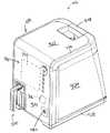
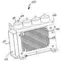
図46および図47は、例示的な真空制御モジュール400および例示的な真空キャニスター500を示している。図示するように、真空キャニスター500は、真空制御モジュール400内に挿入するように構成されている。詳細を後述するように、真空制御モジュール400は、真空キャニスター500を介して真空を導入するように動作可能であり、このような真空を、上記したように生検プローブ102、103に伝達することができる。さらに、真空キャニスター500は、生検プローブ102、103の使用中に生検プローブ102、103から送達される流体を収集するように動作可能である。したがって、真空キャニスター500を、生検プローブ102、103と真空制御モジュール400との間の流体インターフェイスと見なすことができる。V. Exemplary Vacuum Control Module and Canister FIGS. 46 and 47 show an exemplary
A.例示的な真空キャニスター
図48〜図51に示すように、真空キャニスター500は、ベース部分502、蓋部分506、およびハンドル508を含む。ハンドル508は、詳細を後述するように、ユーザーが、真空キャニスター500を真空制御モジュール400内に挿入する際、または真空キャニスター500を真空制御モジュール400から引き抜く際にユーザーが把持できるように構成されている。ベース部分502は、実質的に中空であり、生検プローブ102、103から送達される流体(例えば、生理食塩水や血液など)の収集のためのレザバ504となるように構成されている。A. Exemplary Vacuum Canister As shown in FIGS. 48-51, the
本例の蓋部分506は、その側面にトラック530が形成されている。トラック530は、詳細を後述するように、真空制御モジュール400のキャニスターコンパートメント458のレール460に係合するように構成されている。各トラック530は、レール460に係合する際にこれらのトラック530を案内して、真空キャニスター500を真空制御モジュール400のキャニスターコンパートメント458内に挿入しやすくするフレア部分532を有している。他の実施形態では、トラック530は、ベース部分502に設けられている。あるいは、トラック530は、任意の他の適当な位置に任意の他の適当な構造で置換または追加しても良いし、または単に完全に省いても良い。 The
本例では、蓋部分506に、複数の溝510が形成されている。後述するように、溝510は、チューブ402、404、408、410を受容するように構成されている。複数の上部ポート512が、蓋部分506に形成されており、各上部ポート512は、チューブ402、404の1つと結合するように構成されている。具体的には、各上部ポート512は、接続されたチューブ402、404から、ベース部分502によって画定されたレザバ504への流体連通のための通路を画定するように構成されている。蓋部分506はさらに、詳細を後述するように、真空制御モジュール400の真空源412に流体連通して配置できるように構成された真空ポート514を含む。真空ポート514は、詳細を後述するように、相補的な真空ポート462に係合すると、密閉するように構成された一対のOリング534を含む。本開示を読めば、真空源412を用いて真空が生成されると、この真空を、真空ポート514、レザバ504、および上部ポート512を介してチューブ402、404に伝達できることを理解できよう。この真空はさらに、チューブ402、404を介して生検プローブ102、103に伝達することができる。蓋部分506は、ベントチューブ410の開口した端部に通気するように構成されたベント凹部544も含む。このような通気は、詳細を後述する。 In this example, a plurality of
また、蓋部分506は、アクセスポート528に取り外し可能に結合されたキャップ526も含む。キャップ526は、生検システム2の使用中にアクセスポート528を密閉するように構成されている。生検システム2を使用した後に液体がレザバ504に残っている場合は、キャップ526を取り外してレザバ504にアクセスすることができる。もちろん、上記した他の構成要素と同様に、キャップ526およびアクセスポート528は、単なる任意選択であり、所望に応じて、変更、置換、追加、または単に完全に省いても良い。 The
図51に最もよく示すように、ケージ518内にフロート516が設けられており、このフロート518は、蓋部分506の底部からレザバ504内に延びている。フロート516は、球形として示されているが、任意の他の適当な形状を用いても良い。弾性漏斗部材520が、ケージ518内に部分的に配置され、このケージ518に係合している。加えて、疎水性フィルター522が、蓋部分506の下部と漏斗部材520との間に設けられている。導管524が蓋部分506に形成されており、これにより、真空ポート514からフィルター522および漏斗部材520、そしてレザバ504への流体連通が実現している。フィルター522は、レザバ504から導管524および真空ポート514を介した液体(例えば、生理食塩水や血液など)の送達は防止するが、レザバからこれらを介した真空の送達すなわち導入は可能にするように構成されている。 As best shown in FIG. 51, a
フロート516は、液体に浮くが、レザバ504内に真空が導入されても上方に引っ張られない特性(例えば、密度)を有する。言い換えれば、真空源412が作動されて、真空ポート514を介して真空が導入されても、フロート516は、漏斗部材520に対して必ずしも引き上げられない。したがって、漏斗部材520を介してフロート516の周りに真空を伝達することができる。しかし、レザバ504が液体で満たされると、フロート516は、漏斗部材520に向かって浮き上がり始める。最終的に、チューブ402、404および上部ポート512を介してレザバ504内に吸引された液体が、レザバ504内の所定のレベルに達すると、フロート516が漏斗部材520に係合して、フロート516と漏斗部材520との間の流体の通過が十分に防止される。さらに、このようなフロート516と漏斗部材520との間の係合により、真空ポート514によるレザバ504への真空の伝達を防止することができる。このような真空の伝達の遮断は、生検システム2内で検出することができ、真空キャニスター500が実質的に液体で満たされているというある種の通知を発することができる。例えば、真空の遮断により、真空源412を自動停止することができる。また、真空の遮断により、グラフィカルユーザーインターフェイスにおける視覚的表示、および/または可聴信号を発することもできる。 The
当業者であれば、本開示を読めば、フィルター522、フロート516、ケージ518、および漏斗部材520が全て単なる例示であることを理解できよう。実際、このような構成要素に加えて、または代わりとして、任意の他の適当な装置または構造を用いても良い。あるいは、このような構成要素は、単に全て省いても良い。言い換えれば、真空キャニスター500のために様々な他の構造を用いても良く、かつ上記した生検システム2の他の各構成要素と同様に、真空キャニスター500が、本明細書に明確に記載した特定の構造に限定されるものではないことを発明者は企図している。 Those skilled in the art will appreciate from reading this disclosure that
B.例示的なチューブの接続および構造
図50は、溝510内に配置されたチューブ402、404、408、410の例を示している。溝510は、チューブ402、404、408、410を溝510内に保持するように構成された1または複数の機能構造を備えることができる。例えば、内側に向いたリブまたは突出部を、溝510の上部近傍に設けることができる。あるいは、溝510の側壁が、締まり嵌めを画定するか、または溝510の側壁の上部が側壁の底部よりも狭いクリアランスを画定するように傾斜させても良い。あるいは、接着剤を用いて、チューブ402、404、408、410を溝510内に固定しても良い。さらに別の変更形態では、1または複数のキャップ、止め金、または他の部材を、チューブ402、404、408、410の一部の上に取り付けて、チューブ402、404、408、410を溝510内に固定しても良い。チューブ402、404、408、410を溝510内に固定または保持できる他の方法も、当業者には明らかであろう。B. Exemplary Tube Connections and Structures FIG. 50 shows examples of
複数の上部ポート512が、蓋部分506上に形成されており、各上部ポート512は、1本のチューブ402、404が結合されるように構成されている。具体的には、各上部ポート512は、接続されたチューブ402、404から、ベース部分502によって画定されたレザバ504への流体連通のための通路を画定するように構成されている。一実施形態では、キャニスター500は、製品のパッケージングの前にチューブ402、404をプローブ102、103に結合するのに加えて、チューブ402、404、408、410が溝510内に既に配置された状態で予めパッケージングされている。他の実施形態では、キャニスター500および/またはプローブ102、103は、一部または全てのチューブ402、404、408、410を接続しないでパッケージングしても良い。しかし、チューブ402、404、408、410が予め接続された、キャニスター500およびプローブ102、103の一部の実施形態では、後述するようにキャニスター500をキャニスターコンパートメント458内に挿入することを除けば、ユーザーは、すべき唯1つの流体接続としてチューブ408を生理食塩水バッグ444に接続するだけで良い。もちろん、生理食塩水を使用しない実施形態では、ユーザーがキャニスター500をキャニスターコンパートメント458に挿入するとすぐに、生検システム2の流体連通の利用の準備ができる。 A plurality of
図1に示すように、チューブ408がチューブ402内に入り込んでいる。図1および図50に示すように、チューブ410もチューブ402内に入り込んでいる。具体的には、コネクタ446が、ベントチューブ410をチューブ402に接続し、コネクタ448が生理食塩水チューブ408をチューブ402に接続している。図示するように、コネクタ446は、キャニスター500の近傍に設けられ、コネクタ448は、生検プローブ102、103の近傍に設けられている。本例では、コネクタ446、448は、チューブ410と402およびチューブ408と402の間に常に開口した導管を単に画定している。他の実施形態では、コネクタ446、448は、任意の他の適当な構成要素(例えば、弁など)を有しても良い。本開示を読めば、チューブ402、408、410およびコネクタ446、448の構成により、真空、大気、または生理食塩水のいずれかをチューブ402を介して導入または送達できることを理解できよう。これらのチューブのどのチューブ402を介して導入または送達するかの例示的な決定は、詳細を後述する。 As shown in FIG. 1, the
C.例示的な真空制御モジュール
図46、図47、および図52〜図58に示すように、本例の真空制御モジュール400は、外側キャニスター414、真空キャニスタースロット416、ハンドル部分418、およびユーザーインターフェイス700を含む。外側ケーシング414は、後側にディスプレイ画面702が配置されているフェース部分420、容量性スイッチ704、およびスピーカー706を含む。フェース部分420は、このフェース部分420を通してディスプレイ画面702を観察することができ、このフェース部分420を通して容量性スイッチ704を作動させることができ、かつこのフェース部分420を通してスピーカー706からの音を聞くことができるように構成されている。詳細を後述するように、ディスプレイ画面702、スイッチ704、およびスピーカー706は、全体としてユーザーインターフェイス700を構成していると見なすことができる。外側ケーシング414は、上部カバー422、ラップアラウンドカバー(wraparound cover)424、および切取り部426も含む。C. Exemplary Vacuum Control Module As shown in FIGS. 46, 47, and FIGS. 52-58, the
外側ケーシング414は、比較的容易に清掃できるように構成されている。例えば、表面移行部(例えば、フェース部分420、上部カバー422、ラップアラウンドカバー424、および切取り部426などの間)が削減されている。さらに、従来のプッシュボタンまたは他の機械入力部品の代わりとして、容量性スイッチ704がフェース部分420の後側に設けられると、流体が流入する部分および埃が付く部分が、除去はされていないが、縮小されている。 The
図53に示すように、本例の真空制御モジュール400は、ベース部分428も含む。ベース部分428は、このベース部分428から上方に延び、そして互いに内側に向かって延びてハンドル部分418で交わっている一対の直立部材430を有する。したがって、ベース部分428、直立部材430、およびハンドル部分418は、ユーザーがハンドル部分418を持って真空制御モジュール400を持ち運ぶ際に、真空制御モジュール400の重量が、ベース部分428および直立部材430にかかるように構成されている。一実施形態では、直立部材430およびハンドル部分は、ネジ、ボルト、溶接、または他の構成要素や技術を用いるなどして、ベース部材428に固定された単一金属部材によって集合体として形成されている。ハンドル部分418は、このような単一金属部材の周りに形成されたプラスチックオーバーモールドをさらに含んでも良い。もちろん、上記した他の構成要素と同様に、直立部材430およびハンドル部分418は、様々な代替の構造および技術を用いて様々な代替の方法で形成しても良い。 As shown in FIG. 53, the
ハンドル部分418を設けることで、真空制御モジュール400を実質的に携帯型ユニットとして用意することができる。例えば、真空制御モジュール400は、1人のユーザーがハンドル部分418または他の部分を持って比較的容易に真空制御モジュール400を持ち上げて持ち運びできるような大きさおよび重量(例えば、10kg未満)を有することができる。真空制御モジュール400は、カートを備えていても備えていなくても良い。例えば、真空制御モジュール400の携帯性により、テーブル面または他の位置に簡単にセットすることができる。このような携帯性は、MRI室での設定または他の設定で望ましいであろう。 By providing the
本例の真空制御モジュール400は、ファン432およびベント433も含むが、これらの構成要素は、変更または省いても良い。真空制御モジュール400は、接地端子434、USBポート436、およびイーサーネットポート438も含む。加えて、真空制御モジュール400は、真空制御モジュール400を従来のコードでAC電源に接続するためのコードソケット435、および電源スイッチ439を含む。当業者であれば、本開示を読めば、USBポート436および/またはイーサーネットポート438を用いて、限定するものではないが、ローカルまたは遠隔のデスクトップまたはラップトップコンピュータ、インターネット、ローカルエリアネットワーク、および他のネットワーク、記憶装置、または1または複数の特定の画像方式(例えば、磁気共鳴映像法に関連したポッドまたはカートなど)を含め、様々な他の装置に真空制御モジュール400を接続できることを理解できよう。このようなポート436、438により、データおよび/または命令を真空制御モジュール400から外部装置に送信することができる。これに加えてまたは別法として、ポート436、438により、データおよび/または命令を外部装置から真空制御モジュール400に送信することができる。ポート436、438を用いることができる他の方法も、当業者であれば、本開示を読めば明らかになるであろう。同様に、ポート436、438は、所望に応じて、置換、追加、変更、または省いても良いことを理解されたい。 The
図53に示すように、真空ポンプ440が、真空制御モジュール400内に設けられている。真空ポンプ440から生じるノイズを低減するために、マフラー組立体442が真空ポンプ440に接続されている。したがって、本例では、真空ポンプ440およびマフラー組立体442が、真空源412を集合体として形成されているが、任意の他の適当な構成要素を用いても良い。例えば、マフラー組立体442は、単なる任意選択である。真空ポンプ440およびマフラー組立体442は、例えば、ネジ、ボルト、溶接、または他の構成要素や技術を用いてベース部分428に固定されている。例えば、さらにノイズを低減するために、1または複数のゴム式(不図示)または同様の構成要素を、真空ポンプ440とベース部分428との間に配置して、真空ポンプから生じる振動を吸収しても良い。真空ポンプ440から生じるノイズを低減できる他の方法も、当業者であれば、本開示から明らかになるであろう。 As shown in FIG. 53, a
本例では、生理食塩水は、真空制御モジュール400とは別個の従来の生理食塩水バッグ444によって生検システム2に供給される。例えば、生理食塩水バッグ444は、任意の適当な従来の接続具を用いてチューブ408に結合することができる。他の実施形態では、生理食塩水は、真空制御モジュール400内から供給される。例えば、真空制御モジュール400は、チューブ408が取り付けられるポート(不図示)が生理食塩水バッグ444に流体連通した状態で、従来の生理食塩水バッグ444を受容するように動作可能な機能構造(不図示)を含んでも良い。あるいは、真空制御モジュール400は、生理食塩水を供給するための他の種類のレザバをケーシング414内に含んでも良い。他の実施形態では、生理食塩水は、生検システム2に全く使用しない。また、真空制御モジュール400は、ポンプや封入キャニスターなどの加圧空気源を含んでも良いことも理解されたい。このような加圧空気は、限定するものではないが、1または複数の内腔20、40、52を介して加圧空気を供給するため、生検装置100、101内の構成要素(例えば、空気圧モータやアクチュエータなど)を作動させるため、または任意の他の目的を含め、任意の適当な目的のために生検装置100、101に供給することができる。真空制御モジュール400内に含めるまたは他の方法で取り付けることができるさらに他の構成要素も、当業者であれば、本開示から明らかになるであろう。 In this example, saline is supplied to the
D.制御モジュール内の例示的な真空キャニスターポート
図53〜図58に示すように、本例の真空制御モジュール400は、真空キャニスターポート組立体450も含む。真空キャニスターポート組立体450は、ブラケット452、内側ケーシング454、および複数のソレノイド456を含む。ブラケット452は、例えば、ネジ、ボルト、溶接、または他の構成要素や技術を用いてベース部分428に固定されるように構成されている。ヒートシンク459が、ソレノイド456および内側ケーシングうち454と同様に、ブラケット452に固定されている。D. Exemplary Vacuum Canister Port in Control Module As shown in FIGS. 53-58, the
内側ケーシング454は、上記したように真空キャニスター500を受容するように構成されたキャニスターコンパートメント458を画定している。具体的には、レール460が、ブラケット452の内部から内側ケーシング454の側壁を通ってキャニスターコンパートメント458内まで内側に向かって延びている。上記したように、レール460は、真空キャニスター500がキャニスターコンパートメント458内に挿入される際に、真空キャニスター500を案内するために真空キャニスター500のトラック530に係合するように構成されている。各レール460は、本例のトラック530に係合しやすくするためにテーパ部分466を有するが、このテーパ部分466は単なる任意選択である。本開示を読めば、レール460が、別法として、ブラケット452からではなく、内側ケーシング454の側壁のみから内側に延びても良いことを理解できよう。あるいは、レール460は、他の方法で構成または配置しても良いし、完全に省いても良い。
E.例示的な真空キャニスターの迅速接続
本例の内側ケーシング454は、真空ポート462も含む。ポート連結器464が、真空ポート462の反対側の内側ケーシング454の外面に設けられており、このポート連結器464は、真空ポート462に流体連通している。ポート連結器464は、このポート連結器464を真空ポンプ440に流体結合するために、チューブ、ホース、または他の構造に接続するように構成されている。言い換えれば、真空ポンプ440は、真空ポート462を介して真空引きできるように、ポート連結器464に接続されたチューブ(不図示)を介して真空ポート462に流体連通するように配置することができる。真空ポート462は、真空キャニスター500がキャニスターコンパートメント458内に挿入されると真空キャニスター500の真空ポート514に結合するように構成されている。具体的には、真空ポート462は、雄型真空ポート514に相補的な雌型形状を有する。真空ポート514に設けられたOリング534は、真空ポート462と真空ポート514との間を密閉結合するように構成されている。もちろん、真空ポート462と514との間の雄型と雌型の構成を逆にしても良いし、真空ポート462と514との間の他の関係を用いても良い。さらに、Oリング534が置換、追加、または完全に省かれる他の変更形態を用いても良い。E. Example Vacuum Canister Quick Connect The
F.例示的なピンチ弁システム
各ソレノイド456はそれぞれ、ロッド470を含む。各ロッド470は、対応する係合先端部472、474、476、478が一体的に固定されている。各ソレノイド456は、作動されると、先端部472、474、476、478と共にロッド470を、各ソレノイド456に伝達される信号によって選択的に上方または下方に移動させるように動作することができる。ロッド470は、真空キャニスター500がキャニスターコンパートメント458内に挿入されると、先端部472、474、476、478が、ソレノイド456の選択的な作動によってチューブ402、404、408、410に選択的に結合できるように配置されている。具体的には、真空キャニスター500が真空制御モジュール400のキャニスターコンパートメント458内に挿入されると、先端部472は、生理食塩水チューブ408に選択的に結合するように配置され、先端部474は、ベントチューブ410に選択的に結合するように配置され、先端部476は、軸方向真空チューブ404に選択的に結合するように配置され、先端部478は、横方向真空チューブ402に選択的に結合するように配置される。F. Exemplary Pinch Valve System Each
凹部536、538、540、542が、真空キャニスター500の蓋部分506に形成されており、これらの凹部536、538、540、542は、先端部472、474、476、478がチューブ402、404、408、410に完全に結合するための十分なクリアランスを画定するように構成されている。このような結合は、蓋部分506に対してチューブ402、404、408、410を締め付けて(例えば、係合面として蓋部分506を用いて)、チューブ402、404、408、410を介した流体連通を防止する先端部472、474、476、478を含むことができる。
本例では、凹部536は、先端部472の生理食塩水チューブ408への完全な結合を可能にするように構成されており、凹部538は、先端部474のベントチューブ410への完全な結合を可能にするように構成されており、凹部540は、先端部476の軸方向真空チューブ404への完全な結合を可能にするように構成されており、凹部542は、先端部478の横方向真空チューブ402への完全な結合を可能にするように構成されている。先端部472、474、476、478のチューブ402、404、408、410へのこのような完全な結合は、この例では、完全に結合したチューブ402、404、408、410を介した流体の移送を防止する働きをする。言い換えれば、ソレノイド456、ロッド470、および先端部472、474、476、478を用いて、チューブ402、404、408、410に対して弁の機能を果たすようにして、ソレノイド456の選択的な作動により、チューブ402、404、408、410を通る流体の移送を可能にしたり、防止したりすることができる。生検システム2の使用中のチューブ402、404、408、410を介した流体の移送を可能/防止するための適当な組み合わせは、詳細を後述する。 In this example, the
一部の変更形態では、各ソレノイド456は、1または複数の弾性部材(例えば、バネなど)に係合している。例えば、この弾性部材を、ソレノイド456の底部に配置して、この弾性部材を用いて、累積誤差(tolerance stack-up)を制御してチューブ402、404、408、410の力のプロフィールに対してソレノイド456の力のプロフィールを一致させることができる。もちろん、このような弾性部材は、他の部分に配置しても良く、上記した機能に加えてまたは代わりに他の機能を果たしても良い。同様に、他の構成要素を用いて累積誤差を制御して力のプロフィールを一致させても良い。あるいは、このような弾性部材または他の構成要素を単に一切省いても良い。 In some variations, each
本例では、ソレノイド456、ロッド470、および先端部472、474、476、478によって流体制御が行われるが、様々な代替の方法で流体制御できることを理解されたい。例えば、代替の弁装置またはシステムを、真空制御モジュール400内に設けても良い。あるいは、全てまたは一部の弁機能を、生検装置100、102内で行っても良い。例えば、一定の真空を生検装置101、102に導入することができ、生検装置101、102内の弁部材を、この真空を真空内腔40および/またはカッター内腔52に選択的に導入するように動作することができる。他の実施形態では、生検装置100、101内の1または複数のモータを用いて、真空を供給するために生検装置100、101内に配置された真空ポンプを制御することができる。このような真空モータは、このようなポンプを制御するために専用としても良いし、既存のモータ246、272、282、312、322を用いてこのようなポンプを制御しても良い。チューブ402、404、408、410または生検システム2内の他の構成要素を介した流体(例えば、生理食塩水、真空、大気など)の連通を選択的に制御または実現できるさらに他の方法も、当業者であれば、本開示を読めば明らかになるであろう。 In this example, fluid control is provided by
G.例示的な押し潰し可能なチューブ
一部の実施形態では、図59に示すように、チューブ402、404、408、410は、複数の長手方向スロット490が形成されている。本例では、スリット490は、各チューブ402、404、408、410の全長に亘って延びている。他の実施形態では、スリット490は、チューブ402、404、408、410が先端部472、474、476、478によって選択的に係合される部分のチューブ402、404、408、410の長さに沿ってのみ設けられている。チューブ402、404、408、410は、デュロメータ値の低いポリマーから形成され、スリット490を備えている場合、先端部472、474、476、478による押し潰しに対する抵抗が低く、先端部472、474、476、478によって押し潰されたチューブ402、404、408、410で流体連通が十分に遮断される。しかし、チューブ402、404、408、410は、スリット490を備えているにもかかわらず、真空がチューブ402、404、408、410内に導入されても圧壊しない十分な強度を有する。チューブ402、404、408、410は、捩れに耐える十分な厚みを有しても良い。G. Exemplary Crushable Tube In some embodiments, as shown in FIG. 59, the
本開示を読めば、様々な技術を用いてチューブ402、404、408、410にスリット490を形成できることを理解できよう。例えば、チューブ402、404、408、410が、熱プラスチック押出し工程で形成される場合、押出しダイの出口に低温ナイフを配置して、材料が熱い内に材料をカットすることができる。あるいは、チューブ402、404、408、410が、熱硬化性樹脂押出し工程で形成される場合、押出しガイドの出口に高温ナイフを配置して、材料が固まる前に材料をカットすることができる。あるいは、硬化炉または冷却槽の下流でカットすることによってスリット490を形成しても良い。スリット490を形成できる他の方法も、当業者であれば、本開示を読めば明らかになるであろう。スリット490は、任意の他の適当な構成(例えば、スリット490の数、スリット490の深さ、スリット490の長さ、どのチューブ402、404、408、410がスリット490を有するかの選択など)を有することができることを理解されたい。もちろん、スリット490は、単に一切省いても良い。 It will be appreciated from reading this disclosure that slits 490 can be formed in
さらに、1または複数のチューブ402、404、408、410を、例えば、内部を通る血液を隠蔽するために色付きまたは半透明にしても良い。 In addition, one or
H.例示的なモータ制御
本例の真空制御モジュール400は、ホルスター202、302内のモータ246、272、282、312、322を制御するために動作可能なコントローラ480も含む。例えば、1つのコントローラ480が、同じ生検システム2内の異なるモータ246、272、282、312、322におけるモータ間の機能を調整することができる。真空制御モジュール400は、モータの制御信号および出力をケーブル484を介してモータ246、272、282、312、322に送信するためのポート482を含む。他の実施形態では、モータの制御信号は、無線で送信される。本例のホルスター202は、3つのモータ246、272、282を有し、本例のホルスター302は、2つのモータ312、322を有するが、同じコントローラ480およびポート482を用いて各ホルスター202、302を制御することができる。あるいは、各ホルスター202、302は、専用のポートを真空制御モジュール400に備えても良い。H. Exemplary Motor Control The
モータ246、272、282、312、322は、ブラシまたはブラシレス技術の任意の適当な組み合わせを含むことができる。例えば、1または複数のモータ246、272、282、312、322は、光通信を用いるブラシレスモータとしても良い。一部の実施形態では、光通信の使用により、MRI室で見られるような高い周囲磁界に対してある程度のイミュニティを付与することができる。光通信を用いるモータの単なる例示的な例が、参照して開示内容を本明細書に組み入れる、1995年6月13日発行の米国特許第5,424,625号(名称:「反発電動機(Repulsion Motor)」)に開示されている。光通信を用いるモータの別の単なる例示的な例が、参照して開示内容を本明細書に組み入れる、2006年5月30日発行の米国特許第7,053,586号(名称:「ブラシレス反発電動機速度制御システム(Brushless Repulsion Motor Speed Control System)」)に開示されている。 The
単なる例として、1または複数のモータ246、272、282、312、322は、OPTEK OPR5005反射性小型表面取付け光源/検出器センサ対を含んでも良い。適当なセンサは、透過性センサおよび/または反射性センサを含むことができる。さらに、使用する光は、コヒーレント光(例えば、LASER)または、非コヒーレント光(例えば、LEDによって生成される光)とすることができる。可視光スペクトルまたは非可視光スペクトルのいずれかを用いることができる。本例では、IRフォトダイオードおよびIRフォトトランジスタを含む反射性赤外線(IR)センサを用いている。オプトセンサが、プリント回路基板上に120度の増分で円形アレイ状にモータシャフトの周りに配置され、モータの位相コイルと角度が整合している。ロータ上の磁石に整合したフラッグまたは光学断続器(optical interrupter)が、周囲の半分が透過性/非反射性であって残りの半分が反射性/非透過性であるモータシャフトに固定されている。位相コイルが光学センサに適切に整合し、光学フラッグが、ロータ上の磁極に適切に整合すると、ホール効果センサと全く同様に、ロータの60度位置の検出が可能となる。加えて、光学センサからの論理レベル出力を、ホール効果センサの論理レベル出力と同一にすることができるため、コントローラ480などの制御ハードウエアを用いて検出タイプを交換することができる。光通信または他の方法を用いる構造を含め、モータ246、272、282、312、322の他の適当な構造も、当業者であれば、本開示を読めば明らかになるであろう。 By way of example only, one or
本例のコントローラ480は、マサチューセッツ州リンカーン(Lincoln)に所在のパフォーマンス・モーション・デバイシズ社(Performance Motion Devices, Inc.)が販売するMagellan 4軸チップセットを含む。一実施形態では、コントローラ480は、モータ246、272、282、312、322のいずれか1つの位置に基づいた制御にホール効果信号を使用するように構成されている。例えば、上記したように、本例のモータ282、322は、エンコーダホイール292およびセンサ296に動作可能に結合されている。このような構成は、3チャンネル(A、B、およびインデックスパルス)直交エンコーダを提供することができる。このエンコーダは、コントローラ480と協働して、約0.1度の範囲内でのマニホルド144、366の配置の再現性を可能にしている。 The
一部の実施形態では、ホール効果センサを用いて、少なくとも1つのモータ246、272、282、312、322のコミュテーションおよび位置制御の両方を実現している。コントローラ480は、このようなホール効果センサによって供給される信号およびセンサ296によって供給される信号を多重化するように構成されている。これにより、16の異なる信号が、ポート482に結合されてケーブル484内に有効に延びている4本または6本の異なるラインに多重化されている。もちろん、いずれが用いられる場合でも、任意の他の適当な多重化法を用いることができる。コントローラ480によって動作させるためのさらに他の適当な構成および方法も、当業者であれば、本開示を読めば明らかになるであろう。 In some embodiments, Hall effect sensors are used to achieve both commutation and position control of at least one
例示的な動作モード
本開示を読めば、生検システム2を動作させることができる様々な方法が存在することを理解できよう。例えば、チューブ402、404、408、410または生検システム2内の他の構成要素を介して流体(例えば、生理食塩水、真空、大気など)の連通を選択的に制御するために用いられる構造または技術にかかわらず、使用できる様々なタイミングアルゴリズムが存在する。このようなタイミングアルゴリズムは、ユーザーが選択する動作モードによって変更することができる。さらに、動作モード間に重複が存在しうる(例えば、生検システム2は、ある瞬間に2つ以上の動作モードにある場合など)。選択した動作モードに基づいて流体連通のタイミングアルゴリズムを変更できることに加えて、生検システム2の他の動作態様を、選択した動作モードに基づいて変更することができる。例えば、組織サンプルホルダ140、368の動作は、カッター50および生検システム2の他の構成要素の動作と同様に、選択した動作モードに基づいて変更することができる。いくつかの単なる例示的な動作モードを後述するが、他の動作モードも、当業者であれば、本開示を読めば明らかになるであろう。Exemplary Modes of Operation After reading this disclosure, it will be appreciated that there are various ways in which the
A.採取した組織サンプルの例示的な提示
1つの単なる例示的な動作モードは、「サンプル観察」モードを含みうる。このモードでは、マニホルド144、366は、組織サンプル4が採取されたら回転して、ユーザーが次の組織サンプルを採集する前にユーザーが観察できるように組織サンプル4を提示するように構成することができる。具体的には、図60に示すように、組織サンプル4は、この組織サンプル4が初めに採取された時に12時の位置にあるチャンバ166、388内に吸引される。次に、組織サンプル4が3時の位置に来るまでマニホルド144、366を回転させて、ユーザーが生検装置100、101の側面から組織サンプル4を容易に観察できるようにする。この回転は、組織サンプル4がチャンバ166、388内に吸引された直後に行うことができる。あるいは、生検システム2は、組織サンプル4が採取されてから所定時間(例えば、2秒)内にユーザーが入力するか否かを確認するために待つことができ、ユーザーがこの時間内に入力しなかった場合のみ、3時の位置に組織サンプル4を回転させる。A. Exemplary Presentation of Collected Tissue Sample One merely exemplary operating mode may include a “sample viewing” mode. In this mode, the
他のユーザーの入力が行われるまで組織サンプル4が3時の位置に維持されるように、マニホルド144、366の回転位置を維持することができる。例えば、ユーザーが、別の組織サンプル4の採取を望むという入力を行うと、生検システム2が、マニホルド144、366を回転させて、隣接した(next)利用可能なチャンバ166、388(例えば、最後に採取した組織サンプル4が存在するチャンバ166、388に最も近接したチャンバ166、388)をカッター内腔52に整合させることができる。隣接した利用可能なチャンバ166、388がカッター内腔52に整合したら、カッター50を作動させて別の組織サンプル4を採取し、軸方向の真空を用いて、次の組織サンプル4を隣接した利用可能なチャンバ166、388内に吸引することができる。「プローブ内不要物除去」または「吸引」ユーザー入力が設けられている場合は、マニホルド144、366を回転させて、組織サンプル4が存在するチャンバ166、388をカッター内腔52に再び整合させて、後述するように、「プローブ内不要物除去」または「吸引」を行うことができる。同様に、詳細を後述する「スマート除去」サイクルが開始されたら、マニホルド144、366を回転させて、「スマート除去」サイクルを行うことができるように、組織サンプル4が存在するチャンバ166、388をカッター内腔52に再び整合させることができる。 The rotational positions of the
本例の回転シーケンスの例示を図60に示している。ブロック600に示すように、組織サンプルホルダ140、368は、当初は、第1のチャンバ166、388が12時の位置に来るように構成されている。次いで、ブロック602に示すように、組織サンプル4が、第1のチャンバ166、388に送達されている。「サンプル観察」モードで動作している場合は、ブロック604に示すように、第1のチャンバ166、388が3時の位置に来るようにマニホルド144、366を回転させる。ブロック606に示すように、ユーザー入力を受け取ると、別のサンプル採集サイクルを開始し、マニホルド144、366を回転させて、第2のチャンバ166、388を12時の位置に配置し、組織サンプル4をカッター内腔52を介して第2のチャンバ166、388に送達する。ブロック608に示すように、次いで、マニホルド144、366を回転させて、第2のチャンバ166、388を3時の位置に配置して、ユーザーに第2の組織サンプル4を提示する。ブロック610に示すように、第3のチャンバ166、388内に組織サンプル4を収集するために本例の手順を繰り返す。組織サンプルホルダ140、368内の全てのチャンバ166、388が満たされるまで、この手順を繰り返すことができる。 An example of the rotation sequence of this example is shown in FIG. As shown in
ユーザー入力を待つ代わりとして、ユーザーが入力するしないにかかわらず、マニホルド144、366を自動的に回転させて隣接した利用可能なチャンバ166、388をカッター内腔52に整合させた状態で、組織サンプル4を一定時間(例えば、5秒間)3時の位置に維持することができる。別の限定目的ではない変更形態として、生検システム2は、ユーザーが、上記したようにマニホルド144、366を回転させるある種の入力を所定時間内に行わなければ、組織サンプル4を所定時間のみ3時の位置に維持することができる。タイミングおよび/またはユーザー入力を用いて、組織サンプル4が3時の位置に維持される時間を決定することができるさらに他の方法も、当業者であれば、本開示を読めば明らかになるであろう。このようなマニホルド144、366の回転の制御は、エンコーダホイール292およびセンサ296からのフィードバックと組み合わせて、または任意の他の適当な構成要素を用いて、コントローラ480によって少なくとも部分的に行うことができることを理解されたい。 As an alternative to waiting for user input, regardless of whether the user inputs,
また、生検システム2は、組織サンプル4の提示のために上記した3時の位置の代わりに9時の位置(または任意の他の位置)をユーザーが選択できるように構成しても良い。生検システム2は、ユーザーが「サンプル観察」モードを無効できるようにして、組織サンプル4の採取間のマニホルド144、366の回転だけで、隣接した利用可能なチャンバ166、388をカッター内腔に整合させるようにしても良い。生検システム2の他の変更形態は、「サンプル観察」モードまたは類似のモード、ならびにこのようなモードに使用されうる構成要素を一切備えないようにしても良い。 Further, the
B.例示的な「サンプル採集」サイクル
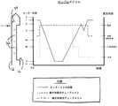
上記した「サンプル観察」モードと重なりうる別の例示的な動作モードは、「サンプル」サイクルを開始することができる「サンプル採取」モードである。「サンプル」サイクルにおいて、チューブ402、404を介して得られる流体連通に対する外側カニューレ12内のカッター50の位置の例示的なシーケンスが図61に示されている。このサイクルは、針部分10が患者の乳房内に挿入されてから開始される。針部分10が挿入された状態で、横方向真空および軸方向真空をかける。具体的には、ソレノイド456が作動されて、先端部476、478が上方に移動してチューブ402、404が実質的に係合解除され、チューブ402、404を介して真空を供給することができる。チューブ402と針マニホルド80、366ならびに壁30を貫通する横方向開口32が流体連通している場合、チューブ402を介した真空の供給により、カニューレ内腔20に対して横方向真空がかかる。この例では、チューブ404が組織サンプルホルダ140、368を介してカッター内腔52に流体連通している場合、チューブ404を介した真空の供給により、カッター内腔52内に軸方向真空がかかる。B. Exemplary “Sample Collection” Cycle Another exemplary mode of operation that may overlap with the “Sample Observation” mode described above is a “Sample Collection” mode that can initiate a “Sample” cycle. An exemplary sequence of the position of
上記したように軸方向真空および横方向真空がかかると、カッター50は、軸方向に引き戻される。このような軸方向の引戻しは、上記したように、モータ272、312およびカッターの回転/並進機構120を用いて行われる。カッター50の軸方向の引戻しにより、開口16が開き、これにより上記した真空の影響を受けて組織が開口16内に導入される。カッター50は、組織が十分に導入されるように所定時間に亘って引戻し位置に維持することができる。 As described above, when the axial vacuum and the lateral vacuum are applied, the
次いで、カッター50を遠位側に前進させて、開口16内に導入された組織を切除する。このような前進は、カッター50の引戻しの際にモータ272、312が回転する方向とは反対方向にモータ272、312を単に回転させて行うことができる。一部の実施形態では、真空内腔40は、カッター50が前進する際に真空から生理食塩水に切り替えられる。例えば、ソレノイド456が、先端部478を下方に移動させてチューブ402を締め付けて、チューブ402を介した真空のさらなる供給を防止し、先端部472を上方に移動させてチューブ408を実質的に係合解除して、チューブ408、402を介した生理食塩水の連通を可能にする。一部の他の実施形態では、真空内腔40は、カッター50が前進する際に真空から通気に切り替えられる。例えば、ソレノイド456が、先端部478を下方に移動させてチューブ402を締め付けて、チューブ402を介した真空のさらなる供給を防止し、先端部474を上方に移動させてチューブ410を実質的に係合解除して、チューブ408、402を介した通気(例えば、大気へ)を可能にする。さらに他の実施形態では、真空内腔40は、生理食塩水の連通と通気を交互に行う。カッター50が前進する際は、カッター内腔52を介した軸方向真空の供給を続ける。 The
カッター50の遠位端部が開口16の遠位縁を通過すると、カッター50が開口16を閉じ、導入された組織が切除され、少なくとも最初はカッター内腔52内に受容される。横方向開口32は、カッター50が開口16を閉じる位置に達しても、少なくとも1または複数の横方向開口32がカッター50によって覆われないように構成すべきである。開口16が閉じて、チューブ402を介して横方向開口32によって通気されている状態では、チューブ404によってカッター内腔52に供給される軸方向真空が、切除された組織サンプル4を、カッター内腔52を介して組織サンプルホルダ140、368のチャンバ166、388内に近位側に吸引する。また、カッター回転/並進機構120を制御して、遠位位置の僅かな運動範囲でカッター50を1または複数回往復運動させて、カッター50の1回目の通過で完全には切除されていない残りの部分を切除することもできる。 As the distal end of the
組織サンプル4がカッター内腔52内を近位側に移送される前に、開口16がカッター50によって閉じられ、真空内腔40がチューブ402、410によって通気され、カッター内腔52を介してチューブ404によって軸方向真空が供給されると、カッター50が僅かに引き戻されて、短時間、開口16の一部が露出される。この時に、チューブ402、408によって真空内腔40に生理食塩水を大気圧で供給することができる。カッター50のさらなる引戻しにより、より多くの横方向開口32が露出され、真空内腔40とカニューレ内腔20との間の流体連通が増大する。また、カッター50の引戻しにより、組織キャビティ(ここから組織サンプル4を得ることができる)の圧力が組織サンプル4の遠位面にかかる。この特定の例では、カッター50が僅かに引き戻されると、大気圧が組織サンプル4の遠位面にかかる可能性が増大して、切除された組織サンプル4が針部分10内に維持されないように助ける(「ドライタップ」とも呼ぶ)。次いで、カッター50を完全に遠位側に前進させて、開口16および全ての横方向開口32を閉じる。このような横方向開口32の閉鎖により、この時(サンプル採取とサンプル採取の間)に苦痛を緩和するために薬物を供給する場合は、薬物を、横方向開口32、カッター内腔52、および組織サンプルホルダ140、368を介して吸引するのではなく、外部開口22を介して乳房空洞部に到達させる。 Before the tissue sample 4 is transported proximally within the
カッター50が完全に前進して(例えば、全ての横方向開口32および開口16が閉じられ)、切除された組織サンプル4が、チューブ404による軸方向真空引きによってカッター内腔52を介してチャンバ166、388内に近位側に移送されると、生検装置100、101が準備完了状態になる。この準備完了状態では、真空内腔40は、大気に通じており、軸方向真空チューブ404が密閉されている(空転状態(dead-headed)とも呼ぶ)。言い換えれば、先端部472は、生理食塩水チューブ408を締め付けて、このチューブ408を介した流体連通を防止し、先端部474は、ベントチューブ410から実質的に係合解除されて、このチューブ410を介して大気に通じることができ、先端部476は、軸方向真空チューブ404を締め付けて、このチューブ404を介した流体連通を防止し、先端部478は、横方向真空チューブ404を締め付けて、このチューブ402を介した流体連通を防止している。この準備完了状態では、生検装置100、101は、例えば、上記したように別のサンプル採取シーケンスを開始することにより、別の組織サンプル4を採取する準備ができている。 The
「サンプル」サイクルは、様々な代替の方法で行うことができることを理解されたい。例えば、カッター50の運動は、組織サンプルを採取する処置の際に変更しても良い。さらに、横方向真空、軸方向真空、通気、および生理食塩水のタイミング、シーケンス、およびこれらの間の相互関係は、様々な方法で変更しても良い。したがって、発明者は、このような可変要素の様々な他の順序変更が可能であり、明確かつ詳細に上記した単なる例示的な順序変更に本発明が一切限定されるものではないと考える。 It should be understood that the “sample” cycle can be performed in a variety of alternative ways. For example, the motion of the
C.例示的な「プローブ内不要物除去」サイクル
生検装置100、101の使用中のある時点で、生検装置100、101が、組織または他の破片が詰まっている兆候が出る場合があることを理解されたい。このような兆候は、当業者であれば、本開示を読めば明らかになるであろう。このような時点または別の時点で、生検装置100、101の性能を向上させるために、このような組織または細片を除去できるシーケンスを開始するのが望ましいであろう。このために、生検システム2は、「プローブ内不要物除去」サイクルの開始を許可することができる。単なる例示的な「プローブ内不要物除去」サイクルは、詳細を後述するが、当業者であれば、「プローブ内不要物除去」サイクルの他の変更形態も、本開示を読めば明らかになるであろう。図62は、例示的な「プローブ内不要物除去」サイクルにおけるチューブ402、404を介して得られる流体連通に対する針部分10内のカッター50の位置の例示的なシーケンスを示している。C. Exemplary “removal of unwanted in probe” cycle At some point during use of the
生検システム2が上記した「サンプル観察」モードにある際に本例の「プローブ内不要物除去」サイクルを開始する場合は、マニホルド144、366を回転させて、チャンバ166、388を、3時の位置(または9時の位置)から12時の位置に戻す。本例の「プローブ内不要物除去」サイクルが開始された時に生検システム2が「サンプル観察」モードにないと、マニホルド144、366は回転しない。次いで、カッター50を僅かに引き戻して、短時間、開口16の一部を露出させる。この露出時間中に、空気および/または生理食塩水(大気圧)をチューブ402を介して連通させる。また、この露出時間中に、真空をチューブ404を介して供給する。次いで、カッター50を前進させて、全ての横方向開口32を覆わずに開口16を閉じる。この同じサイクルを数回(例えば、1回から4回など)繰り返して、「プローブ内不要物除去」サイクルを完了する。「プローブ内不要物除去」サイクルが終了したら、生検システム2が準備完了状態に入る。次の「サンプル」サイクルが所定時間(例えば、数秒間)内に開始されない場合は、次の「サンプル」サイクルが開始されるまで「サンプル観察」モードを再開することができる。 When the
「プローブ内不要物除去」サイクルは、様々な代替の方法で行うことができることを理解できよう。例えば、カッター50の運動は、プローブ102、103内不要物を除去する工程の際に変更しても良い。さらに、横方向真空、軸方向真空、通気、および生理食塩水のタイミング、シーケンス、およびこれらの間の相互関係は、様々な方法で変更しても良い。したがって、発明者は、このような可変要素の様々な他の順序変更が可能であり、明確かつ詳細に上記した単なる例示的な順序変更に本発明が一切限定されるものではないと考える。 It will be understood that the “removal of unwanted matter in the probe” cycle can be performed in various alternative ways. For example, the movement of the
D.例示的な「位置合わせ(position)」サイクル
図63は、例示的な「位置合わせ」サイクルにおけるチューブ402、404を介して得られる流体連通に対する針部分10内のカッター50の位置の例示的なシーケンスを示している。開口16が閉じられて(例えば、カッター50が遠位位置まで前進して)、生検装置100、101が準備完了状態にある時に「位置合わせ」サイクルを開始する場合は、カッター50を近位側に引き戻す。この時に、チューブ402は、大気に通じた状態に維持し、チューブ404は、先端部476による締付けによって密閉する(空転状態とも呼ぶ)。D. Exemplary “Position” Cycle FIG. 63 illustrates an exemplary sequence of the position of the
「位置合わせ」サイクルは、様々な状況で用いることができる。例えば、超音波ガイド処置または他の処置の際に、開口16が閉じた状態で、針10を組織内に挿入することができる。組織内の開口16の位置を確認するために、「位置合わせ」サイクルを開始して開口16を開け、開口16の視覚化を容易にすることができる。開口16の位置を確認したら、「位置合わせ」サイクルを開始して、開口16を閉じることができる。マーカーを、カッター内腔52を介して開口16から組織内に配置する時に、別の「位置合わせ」サイクルを行うことができる。この状況において、「位置合わせ」サイクルは、組織マーカーを開いた開口16を介して組織内に配置できるように開口16を開けるために開始することができる。「位置合わせ」サイクルの他の適当な使用も、当業者であれば、本開示から明らかになるであろう。 The “alignment” cycle can be used in a variety of situations. For example, the
開口16が開いて(例えば、カッター50が近位位置に引き戻されて)、生検装置100、101が準備完了状態にある時に「位置合わせ」サイクルを開始する場合は、カッター50を遠位側に前進させて開口16を閉じる。この時に、チューブ402は、大気に通じた状態に維持し、チューブ404は、先端部476による締付けによって密閉する(空転状態とも呼ぶ)。 If the
「位置合わせ」サイクルの変更形態を用いて、開口16が「サンプル」サイクルの際の所定の大きさよりも開かないように、カッター50を用いて開口16の大きさを変更しても良い。例えば、患者の皮膚の表面に比較的近い組織サンプル4を得るため、または他の目的のために、比較的長さの短い組織サンプル4を得るべく開口16の長さを短くするのが好ましいであろう。組織サンプル4の採取の際に開口16の大きさを変更するためのカッター50位置の例示的な使用が、参照して開示内容を本明細書に組み入れる、2006年9月7日公開の米国特許出願公開第2006/0200040号(名称:「可変側面開口を備えた生検装置(Biopsy Device with Variable Side Aperture)」)に開示されている。詳細を後述するように、ユーザーインターフェイス700、800を用いて、「サンプル」サイクルの際にどの程度開口16を開けるかを可変的に選択することができる。 A variation of the “alignment” cycle may be used to change the size of the
「位置合わせ」サイクルは、様々な代替の方法で行うことができることを理解されたい。例えば、カッター50の運動は、このカッター50の位置合わせの手順の際に変更しても良い。さらに、横方向真空、軸方向真空、通気、および生理食塩水のタイミング、シーケンス、およびこれらの間の相互関係は、様々な方法で変更しても良い。したがって、発明者は、このような可変要素の様々な他の順序変更が可能であり、明確かつ詳細に上記した単なる例示的な順序変更に本発明が一切限定されるものではないと考える。 It should be understood that the “alignment” cycle can be performed in a variety of alternative ways. For example, the movement of the
E.例示的な「吸引」サイクル
生検処置の際に生検部位から流体を除去するのが望ましいであろう。したがって、本例の生検システム2は、このような流体の除去または他の目的のために用いることができる「吸引」サイクルを含む。図64は、例示的な「吸引」サイクルにおけるチューブ402、404を介して得られる流体連通に対する針部分10内のカッター50の位置の例示的なシーケンスを示している。E. Exemplary “Aspiration” Cycle It may be desirable to remove fluid from the biopsy site during a biopsy procedure. Thus, the
本例の「吸引」サイクルを、生検システム2が上記した「サンプル観察」モードにある時に開始する場合は、マニホルド144、366を回転させて、チャンバ166、388を、3時の位置(または9時の位置)から12時の位置に戻す。生検システム2が、本例の「吸引」サイクルが開始された時に「サンプル観察」モードでないと、マニホルド144、366は回転しない。次いで、吸引ボタン(不図示)を作動させると、またはある種の他のユーザー入力を行うと、このような作動または入力が終わるまでカッター50が引き戻される。したがって、ボタンが押されているまたは他の入力が行われている時間が長ければ長い程、開口15が、より多くカッター50によって露出される。加えて、吸引ボタンを作動させる、または他のユーバー入力を行うと、真空がチューブ402、404の両方を介して供給される。したがって、このような真空は、カッター内腔52を介して軸方向に供給され、横方向開口32を介して横方向(カニューレ20に対して)に供給される。開口16が少なくとも部分的に開いている状態で、チューブ402、404を介して供給される真空は、生検部位から流体を吸引する役割を果たすことができることを理解されたい。このような流体は、本例の真空キャニスター500内に堆積される。 If the “suction” cycle of this example begins when the
吸引ボタンが解放される、または同様のユーザー入力が終了または変更されると、チューブ402は、横方向真空の供給から通気に切り替わることができる。言い換えれば、先端部478が、チューブ402に実質的に係合して、このチューブ402を介した真空のさらなる供給を防止し、先端部474が、チューブ410の係合を実質的に解除して、チューブ410、402を介した通気を可能にするようにソレノイド456を作動させることができる。加えて、先端部476がチューブ404に実質的に係合してチューブ402を介した真空のさらなる供給を防止するなどして、チューブ404を、この時点で密閉する(空転状態とも呼ぶ)。短い停止(例えば、2,3秒)の後、カッター50を完全に遠位側に前進させて、開口16を閉じ、横方向開口32を覆う。次いで、生検装置100、101が、再び準備完了状態になる。 When the suction button is released or similar user input is terminated or changed, the
「吸引」サイクルが開始された時に開口16が開いていると(例えば、カッター50が少なくとも部分的に引き戻されて)、開口16は、「吸引」サイクル中に開いた状態に維持され、吸引ボタンが作動されている間(またはある種の他のユーザー入力が行われている間)、チューブ402、404を介して真空が供給される。吸引ボタンが解放されると(または他のユーザー入力が終了または変更されると)、開口16は開いた状態に維持され、生検装置100、101が再び準備完了状態になる。したがって、カッター50は、「吸引」サイクル中に移動する必要がない。 If the
「吸引」サイクルは、様々な代替の方法で行うことができることを理解されたい。例えば、カッター50の運動は、プローブ102、103を介した吸引の手順の際に変更しても良い。さらに、横方向真空、軸方向真空、通気、および生理食塩水のタイミング、シーケンス、およびこれらの間の相互関係は、様々な方法で変更しても良い。したがって、発明者は、このような可変要素の様々な他の順序変更が可能であり、明確かつ詳細に上記した単なる例示的な順序変更に本発明が一切限定されるものではないと考える。 It should be understood that the “suction” cycle can be performed in a variety of alternative ways. For example, the motion of the
F.例示的な「スマート除去(Smart Vac)」サイクル
生検システム2の使用中に、組織サンプル4を一定時間採取しないで患者の乳房内に針部分10が挿入されて維持される場合がある。このような時は、生検部位から流体を除去するのが望ましいであろう。したがって、本例の生検システム2は、このような時にこのような流体を周期的に除去するため、または他の目的のために用いることができる「スマート除去」サイクルを含む。図65は、例示的な「スマート除去」サイクルにおけるチューブ402、404を介して得られる流体連通に対する針部分10内のカッター50の位置の例示的なシーケンスを示している。F. Exemplary “Smart Vac” Cycle During use of the
生検システム2が延長された時間(例えば、1分、30秒、または他の時間など)に亘って準備完了状態であり、このような延長時間の際にユーザー入力が一切行われない時に、本例の「スマート除去」サイクルを開始することができる。このような休止時間により、「スマート除去」サイクルが自動的に開始され、これによりカッター50が僅かに引き戻されて、短時間(例えば、3秒)の間、開口16の一部を露出させることができる。カッター50が僅かに引き戻された状態で、チューブ402、404を介して真空を供給して生検部位から流体を除去する。次いで、カッター50を自動的に前進させて開口16を閉じ、生検システム2を準備完了状態に戻す。第1の「スマート除去」サイクルが完了してから所定時間以内にさらなるユーザー入力が行われないと、「スマート除去」サイクルが再び自動的に繰り返される。この処置は、無期限に繰り返すことができる。 When the
代替の実施形態では、「スマート除去」サイクル中の真空のレベルは、他の動作サイクル中の真空レベルよりも低くすることができる。このような低い真空レベルは、様々な方法で実現することができる。例えば、先端部476、478がチューブ402、404を部分的に締め付けて制限はするけれども、チューブ402、404を介した流体連通が遮断されないようにする。あるいは、真空ポンプ440の動作を変更して、真空ポンプ444によって生成される真空レベルを調節することができる。真空レベルを変更できる他の方法も、当業者であれば、本開示を読めば明らかになるであろう。 In an alternative embodiment, the level of vacuum during the “smart removal” cycle can be lower than the vacuum level during other operating cycles. Such a low vacuum level can be achieved in various ways. For example, the
「スマート除去」サイクルは、様々な代替の方法で行うことができることを理解されたい。例えば、カッター50の運動は、生体部位から流体を除去する処置の際に変更しても良い。さらに、横方向真空、軸方向真空、通気、および生理食塩水のタイミング、シーケンス、およびこれらの間の相互関係は、様々な方法で変更しても良い。したがって、発明者は、このような可変要素の様々な他の順序変更が可能であり、明確かつ詳細に上記した単なる例示的な順序変更に本発明が一切限定されるものではないと考える。 It should be understood that the “smart removal” cycle can be performed in a variety of alternative ways. For example, the movement of the
VII.真空制御モジュールの例示的なユーザーインターフェイス
上記したように、ディスプレイ画面702、スイッチ704、およびスピーカー706は、全体としてユーザーインターフェイス700を構成していると見なすことができる。加えて、上記したように、フェース部分420は、このフェース部分420を介してディスプレイ画面702を視認できるように構成されており、容量性スイッチ704は、フェース部分420を介して作動させることができ、スピーカー706から出る音は、フェース部分420を介して聞くことができるように構成されている。容量性スイッチ704は、ユーザーの指がこのスイッチ704に十分に近づくと作動するように構成されている。具体的には、容量性スイッチ704は、磁界を生成し、ユーザーの指が近づくと磁界が妨害され、これを、指が近付けられたスイッチ704が検出することができる。容量性スイッチ704は、容量性スイッチ704を作動させるためにユーザーがフェース部分420に接触さえしなくても良いように十分な感度を有することができる。言い換えれば、容量性スイッチ704は、スイッチ704を作動させるためにユーザーの指が容量性スイッチ704の上のフェース部分420から所定の距離に到達するだけで良いように構成しても良い。もちろん、任意の他の適当な「非接触」技術(例えば、超広域レーダーなど)を、容量性スイッチ704の代わりまたはこれに加えて用いても良い。あるいは、他の入力装置(例えば、従来のボタン、スイッチ、スライダー、ダイヤルなど)を用いても良い。VII. Exemplary User Interface of Vacuum Control Module As described above, the
本例の容量性スイッチ704は、LED(不図示)で補完されている。具体的には、LEDが、関連する容量性スイッチ704がユーザーによって十分に作動されると視覚フィードバックを行うように、各容量性スイッチ704に対して配置されている。例えば、各容量性スイッチ704に関連したLEDは、初期設定によって点灯したままであり、その関連する容量性スイッチ704が十分に作動されると消灯に変わる。あるいは、各容量性スイッチ704に関連したLEDは、初期設定によって消灯されたままであり、その関連する容量性スイッチ704が十分に作動されると点灯に変わる。また、LEDを用いて、真空制御モジュール400の状態についての視覚フィードバックを行っても良い。例えば、状態LEDは、真空制御モジュール400が動作している時は常に点灯した状態とし、真空制御モジュール400が「スリープモード」(例えば、電源は入っているが活用されていない)にある時はパルス(例えば、減衰と増強)にすることができる。LEDや他の光源または視覚的表示を、容量性スイッチ704または他の要素と共に真空制御モジュールに組み入れることができる他の方法も、当業者であれば、本開示を読めば明らかになるであろう。 The
加えて、スピーカー706は、真空制御モジュール400の使用に関連したフィードバックを強化するために可聴音を発することができる。例えば、スピーカー706は、容量性スイッチ704が作動した時に音を発することができる。加えて、特定のスイッチ704は、専用の特定の音または音響パターンを有しても良い。同様に、詳細を後述する選択および動作などのユーザーのスイッチ704の作動によって行われる特定の選択はそれぞれ、区別できる音、関連した音、または音響パターンを有しても良い。もちろん、可聴音、音響パターン、またはスピーカー706の他の使用を真空制御モジュール400に組み入れることができ、これを様々な代替の方法で用いることができる。 In addition, the
図66〜図68は、ユーザーインターフェイス700の他の態様を示している。具体的には、図66〜図68は、ディスプレイ画面702上に表示することができる様々な例示的な画面720、740、760を示している。これらの単なる例示的な各画面720、740、760は、詳細を後述する。一実施形態では、フェース部分420およびディスプレイ画面702は、ディスプレイ画面702の周囲がフェース部分420を介して視認できないように構成されている。さらに、フェース部分420は、ディスプレイ画面702に関連した周囲を一切画定していない。したがって、ディスプレイ画面702上に表示されるテキスト、アイコン、および他の視覚的表示は、真空制御モジュール400のフェース部分に浮かんで出現する。もちろん、このような構成は、単なる任意選択である。 66-68 show other aspects of the
同様に図66〜図68に示すように、容量性スイッチ704は、画面720、740、760に近接して垂直方向に整合されたボタン708、710として表示されている。ボタン708、710は、画面720、740、760をサイクルさせるために用いる上部ボタン708と、表示画面720、740、760に対して入力を選択するために用いられる下側ボタン710を含む。具体的には、上部ボタン708が作動されるたびに、この作動により、ディスプレイ画面702が、表示画面を1つの画面720、740、760を次の画面720、740、760に変更する。 Similarly, as shown in FIGS. 66-68, the
各画面720、740、760は、それぞれに関連した対応するタブ722、742、762を有する。具体的には、「状態」タブ722は、状態画面720に関連し、「プローブ」タブ742は、プローブ画面740に関連し、「システム」タブ762は、システム画面760に関連している。タブ722、742、762は、対応する各画面720、740、760の上部に配置されており、所定の画面720、740、760が表示されている時でも他の画面720、740、760のタブ722、742、762も視認することができる。例えば、図66では、状態画面720が表示されているが、「プローブ」タブ742および「システム」タブ762も視認することができる。しかし、図66では、「状態」タブ722は、「プローブ」タブ742および「システム」タブ762よりも明るく点灯されている。図67では、プローブ画面740が表示されており、図68では、システム画面762が表示されている。当業者であれば、本開示を読めば、タブ722、742、762が単なる例示であり、タブ722、742、762を、様々な代替の方法でユーザーインターフェイス700に組み入れることができることを理解できよう。さらに、タブ722、742、762に加えてまたは代わりとして、使用できる様々な代替の機能構造が存在する。 Each
A.例示的な「状態」画面
再び図66を参照すると、単なる例示的な状態画面720は、いくつかの視覚的表示724、726、728、730を含む。例えば、「サンプル観察」表示724は、生検システム2が「サンプル観察」モードであるか否かを示しており、この例を詳細に後述する。図示するように、この例の「サンプル観察」表示724は、「サンプル観察」モードがオフであることを示すために丸に斜線のマークとして示されているアイコンを含む。「サンプル観察」モードがいつオンになったかを示すためにチェックマークまたは他の表示を用いても良い。詳細を後述するように、ユーザーは、プローブ画面740が表示されている時に「サンプル観察」モードをオンまたはオフにすることができる。もちろん、「サンプル観察」モードの状態を示すために、丸に斜線のマークおよび/またはチェックマークに加えてまたは代わりとして他の適当な視覚的表示を用いても良い。A. Exemplary “Status” Screen Referring again to FIG. 66, the exemplary
「真空レベル」表示726も、状態画面720に示されている。図示するように、この例の「真空レベル」表示726は、生検システム2の真空レベルを示すために一連の昇順バーとして示されているアイコンを含む。ユーザーは、詳細を後述するように、システム画面760が表示されている時に生検システム2の真空レベルを調節することができる。真空レベルの漸進的増大は、この例では、「真空レベル」表示726の一連の昇順バーにおける点灯バーの追加によって示される。言い換えれば、「真空レベル」表示726において点灯されているバーの数が、生検システム2の真空レベルを示す。もちろん、生検システム2内の真空レベルを示すために、昇順バーに加えてまたは代わりとして、任意の他の適当な視覚的表示(例えば、模擬針ゲージまたは数字など)を用いても良い。 A “vacuum level”
「針開口」表示728も、状態画面720に示されている。図示するように、この例の「針開口」表示726は、カッターが明るく点灯されている針端部として示されているアイコンを含む。この「針開口」表示726を用いて、生検システム2の使用中にカッター50が針部分10内に引き戻される最大距離を示すことができる。例えば、「位置合わせ」サイクルの文脈で記載したように、ユーザーは、開口16が乳房内で開く程度を制限するためにカッター50の近位側への運動を制限することを望む場合がある。生検処置の際に開口16の開きを変更するためのカッター50のこのような使用が、参照して開示内容を本明細書に組み入れる、2006年9月7日公開の米国特許出願公開第2006/0200040号(名称:「可変側面開口を備えた生検装置(Biopsy Device with Variable Side Aperture)」)に開示されている。ユーザーは、詳細を後述するように、プローブ画面740が表示されている時にこの有効針開口16を調節することができる。「針開口」表示726におけるアイコンの針部分に対する「針開口」表示726におけるアイコンのカッター部分の位置は、ユーザーが設定した有効針開口16を示すことができる。もちろん、ユーザーが設定した有効針開口を示すために、針およびカッター端部のレンダリングに加えてまたは代わりとして、任意の他の適当な視覚的表示を用いても良い。 A “needle opening”
「スマート除去パルス」表示730も、詳細を後述するように、生検システム2が「スマート除去」モードにあるか否かを示すために状態画面720に示されている。図示するように、この例の「スマート除去パルス」表示730は、「スマート除去パルス」モードがオンであることを示すためにチェックマークとして示されているアイコンを含む。丸に斜線のマークまたは他の表示を用いて、「スマート除去パルス」モードがいつオフになったかを示すことができる。ユーザーは、詳細を後述するように、プローブ画面740が表示されている時に「スマート除去」モードをオンまたはオフにすることができる。もちろん、「スマート除去」モードの状態を示すために、丸に斜線のマークおよび/またはチェックマークに加えてまたは代わりとして、他の適当な視覚的表示を用いても良い。 A “smart removal pulse”
上記を考慮すると、本例の状態画面720は、生検システム2内のいくつかの可変要素の状態を示すために単に用いられている。この特定の例の状態画面720は、これらの可変要素のいずれかを変更するため、または生検システム2の動作を他の方法で変更するためのユーザー入力を受け付けないように構成されている。ボタン710は、状態画面720が表示されている時は表示されていない。可変要素のいずれかを変更する際は、ユーザーが、状態画面720の上部ボタン708を作動させて、表示画面を状態画面720からプローブ画面740またはシステム画面760に変更し、可変要素を変更するべく入力しなければならない。しかし、他の実施形態では、状態画面720では、ユーザーは、状態がこの状態画面720に示されている可変要素の一部または全てを変更することができる。状態画面720または他の画面を実現できる他の方法も、当業者であれば、本開示を読めば明らかになるであろう。加えて、一部の実施形態では、状態画面720が、単に全て省かれている(例えば、プローブ画面740およびシステム画面760および/または他の画面のみが用いられるなど)。 In view of the above, the
B.例示的な「プローブ」画面
再び図67を参照すると、単なる例示的なプローブ画面740は、いくつかの視覚的表示744、746、748、750を含む。例えば、「開口」表示742は、生検システム2の使用中に針部分10内でカッター50が引き戻される最大距離を示している。例えば、上記したように、ユーザーは、開口16が乳房内で開く程度を制限するためにカッター50の近位側への運動を制限したい場合がある。ユーザーは、「開口」表示742の隣にあるボタン710を作動させてこの有効針開口16を調節することができる。ユーザーがこのボタン710を作動させるたびに、生検システム2が、コントローラ480などによって有効針開口16に適宜調節を行うことができる。このような調節は、開口16を50%開、75%開、または100%開などの増分で増大させることができるが、他の増分を用いても良い。加えて、ユーザーがこのボタン710を作動させるたびに、「開口」表示742におけるアイコンのカッター部分が、「開口」表示742におけるアイコンの針部分に対して移動する。ユーザーが選択した針の最大近位位置を強調するために、矢印が、アイコンの針部分の上に示されている。さらに、テキスト表示(例えば、「Sm」は、小さい開口16、「Lg」は大きい開口など)を、ユーザーが選択した有効開口16の大きさをさらに示すために含めても良い。B. Exemplary “Probe” Screen Referring again to FIG. 67, a mere
プローブ画面740上の「開口」表示742は、状態画面720上の「針開口」表示728に類似しているが、「プローブ画面740上の「開口」表示742が、ユーザーが選択した有効開口16の長さについての追加情報を示す点が異なっている。さらに、本例の状態画面720とは異なり、プローブ画面740は、ユーザーが、「開口」表示742の隣にあるボタン710を作動させることによって有効開口16の長さを調節することができる。ユーザーによるボタン710の各作動により、開口16の有効長さが、0に達するまで漸進的に減少し、0に達した時点で、ボタン710をさらに作動させると、開口16の有効長さがその全長まで「フリップバック(flipping back)」する。開口16の有効長さの漸進的な変更を可能にする代替として、ユーザーインターフェイス700により、ユーザーが、入力装置のタッチ式仮想表示(例えば、タッチ式画面上など)の使用を含め、スライダー、ダイヤル、ノブなどを用いて開口16の有効長さを漸進的に変更することができる。ユーザーが開口16の有効長さを調節することができる他の方法も、当業者であれば、本開示を読めば明らかになるであろう。加えて、ユーザーが設定した針の有効開口を示すために、針およびカッター端部のレンダリングに加えてまたはこの代わりとして、任意の他の適当な視覚的表示を用いても良い。 The “opening”
本例のプローブ画面740は、上記したように生検システム2が「サンプル観察」モードであるか否かを示す「サンプル観察」表示746も含む。図示するように、この例の「サンプル観察」表示746は、「サンプル観察」モードがオフであることを示すために丸に斜線のマークとして示されているアイコンを含む。「サンプル観察」モードをオンにする際は、ユーザーが、「サンプル観察」表示746の隣のボタン710を作動させることができる。「サンプル観察」モードがオンであることを示すために丸に斜線のマークの代わりとして、チェックマーク、他のアイコン、または表示を用いても良い。「サンプル観察」モードをオフに戻す際は、ユーザーが、同様に「サンプル観察」表示746の隣のボタン710を作動させることができる。 The
本開示を読めば、プローブ画面740上の「サンプル観察」表示746は、状態画面720上の「サンプル観察」表示724に類似しているが、プローブ画面740では、ユーザーが、「サンプル観察」表示746の隣にあるボタン710を作動させて「サンプル観察」モードをオン・オフできる点が異なっていることを理解できよう。もちろん、「サンプル観察」モードの状態を示すために、丸に斜線のマークおよび/またはチェックマークに加えてまたは代わりとして、他の適当な視覚的表示を用いても良い。 After reading this disclosure, the “sample observation”
本例のプローブ画面740は、「回転式リセット」表示748も含む。「回転式リセット」表示748は、マニホルド144、366の位置をリセットするために作動させることができる、「回転式リセット」表示748の隣にあるボタン710を示している。具体的には、上記したように、一部の実施形態では、生検装置100、101の使用中に、エンコーダホイール292およびセンサ296を用いてマニホルド144、366の回転位置をトラッキングする。ユーザーがマニホルド144、366を交換すると、カッター内腔52に整合していると生検システム2が見なしている最後のチャンバ166、388がカッター内腔52に整合しなくなるため、ユーザーは、新しいマニホルド144、366がプローブ102、103に結合したことを生検システム2に示すために「回転式リセット」表示748の隣にあるボタン710を作動させることができる。この結果、生検システム2が、所定のチャンバ166、388または通路158がカッター内腔52に整合していると見なす。ユーザーがマニホルド144、366を手動で回転させて所定のチャンバ166、388をカッター内腔52に整合させた時などの他の事情で、「回転式リセット」表示748の隣にあるボタン710を作動させることもできる。 The
本例のプローブ画面740は、詳細を後述するように、生検システム2が「スマート除去」モードにあるか否かを示す「スマート除去パルス」表示750も含む。図示するように、この例の「スマート除去パルス」表示750は、「スマート除去」モードがオンであることを示すためにチェックマークとして示されているアイコンを含む。丸に斜線のマークまたは他の表示を用いて、いつ「スマート除去」モードがオフになったかを示すことができる。「スマート除去」モードをオフにする際は、ユーザーが、「スマート除去パルス」表示750の隣にあるボタン710を作動させることができる。丸に斜線のマーク、他のアイコン、または表示を、「スマート除去」モードがオフになったことを示すためにチェックマークと交換しても良い。「スマート除去」モードをオンに戻す際は、ユーザーが、同様に「スマート除去パルス」表示750の隣にあるボタン710を作動させることができる。 The
本開示を読めば、プローブ画面740上の「スマート除去パルス」表示750が、状態画面720上の「スマート除去パルス」表示730に類似しているが、プローブ画面740では、ユーザーが、「スマート除去パルス」表示750の隣にあるボタン710を作動させて「スマート除去」モードをオン・オフできる点が異なっていることを理解できよう。もちろん、「スマート除去」モードの状態を示すために、丸に斜線のマークおよび/またはチェックマークに加えてまたは代わりとして、他の適当な視覚的表示を用いても良い。 After reading this disclosure, the “smart removal pulse”
C.例示的な「システム」画面
再び図68を参照すると、単なる例示的なシステム画面760は、いくつかの視覚的表示764、766、768、770を含む。例えば、「真空レベル」表示764が、システム画面760上に示されている。図示するように、この例の「真空レベル」表示764は、生検システム2の真空レベルを示すために一連の昇順バーとして示されているアイコンを含む。生検システム2の真空レベルを調節する際は、ユーザーが、「真空レベル」表示764の隣にあるボタン710を作動させることができる。ユーザーがこのボタン710を作動させるたびに、生検システム2の真空レベルを漸進的に上昇させることができる。このような漸進的な上昇は、「真空レベル」表示764の一連の昇順バーにおける点灯バーの追加によって示すことができる。言い換えれば、「真空レベル」表示764おいて点灯されているバーの数が、生検システム2の真空レベルを示す。C. Exemplary “System” Screen Referring again to FIG. 68, the
全てのバーが点灯されている時(例えば、真空レベルが最も高いことを示すことができる)に関連するボタン710をユーザーが作動させると、真空レベルが最低のレベルまで著しく低下し、一連のバーの第1のバーのみが点灯する。したがって、ユーザーは、「真空レベル」表示764の隣にあるボタン710を繰り返し作動させることによって様々な真空レベルに漸進的に循環させることができ、真空レベルにおけるこれらの漸進的変化を、「真空レベル」表示764の一連の昇順バーで示すことができる。 When the user activates the
システム画面760によってユーザーが選択した真空レベルの制御は、様々な方法で行うことができることを理解されたい。例えば、選択した真空レベルは、真空ポンプ440の動作を変更することによって行うことができる。あるいは、選択した真空レベルは、真空がチューブ402、404を介して供給される際に、先端部476、478がチューブ402、404を係合解除する程度を変更することによって行うことができる。例えば、ソレノイド456を作動させて、先端部476、478が、チューブ402、404を介した真空の供給を遮断することなくチューブ402、404に制限を設けるように、先端部476、478をチューブから僅かに離すことができる。別の変更形態では、任意の適当な位置にある追加の弁(不図示)または他の構成要素を用いて、ユーザーの選択に従って真空レベルを変更する。 It should be understood that control of the vacuum level selected by the user via
本開示を読めば、システム画面760上の「真空レベル」表示764が、状態画面720上の「真空レベル」表示764に類似しているが、システム画面760では、ユーザーが、「真空レベル」表示764の隣にあるボタン710を作動させることによって生検システム2の真空レベルを変更できる点が異なっていることを理解できよう。もちろん、生検システム2内の真空レベルを示すために、昇順バーに加えてまたは代わりとして、任意の他の視覚的表示(例えば、擬似針ゲージおよび数字など)を用いても良い。 After reading this disclosure, the “vacuum level” display 764 on the
本例のシステム画面760は、「音量」表示766も含む。図示するように、この例の「音量」表示766は、スピーカー706によって発せられる音の音量レベルを示すために、サイズが昇順の一連のバーとスピーカーとして示されているアイコンを含む。音量を調節する際は、ユーザーが、「音量」表示766の隣にあるボタン710を作動させることができる。ユーザーがこのボタン710を作動させるたびに、音量が漸進的に増大する。このような漸進的な増大は、「音量」表示766一連の昇順バーにおける点灯バーの追加によって示すことができる。言い換えれば、「音量」表示766において点灯されているバーの数が、スピーカー706によって発せられる音または他の音響の音量を示す。したがって、「音量」表示766およびその関連するボタン710は、上記した「真空レベル」表示764およびその関連するボタン710に類似しているが、「音量」表示766が音量レベルに関連し、「真空レベル」表示764が真空レベルに関連している点が異なる。もちろん、音量レベルを示すために、スピーカーとサイズが増大するバーに加えてまたは代わりとして、任意の他の適当な視覚的表示(例えば、擬似ダイヤルや数字など)を用いても良い。 The
本例のシステム画面760は、「待機中」表示768も含む。図示するように、この例の「待機中」表示768は、星と月として示されているアイコンを含む。生検システム2を待機中モードにする際は、ユーザーが、「待機中」表示768の隣にあるボタン710を作動させることができる。待機中モードの一変更形態では、真空ポンプ440がオフであり、少なくとも一部のユーザー入力装置(例えば、ホルスター202、302上のユーザーインターフェイス800、フットスイッチなど)が非作動状態である。待機中モードの他の変更形態も、当業者であれば、本開示を読めば明らかになるであろう。生検システム2を待機中モードから出る際は、ユーザーが、ユーザーインターフェイス700のいずれかの容量性スイッチ704を単に作動させる、ホルスター202、302上のいずれかのスイッチまたはボタンを作動させる、またはある種他の動作を行うことができる。 The
本例のシステム画面760は、「シャットダウン」表示770も含む。図示するように、この例の「シャットダウン」表示770は、電源ボタンを表すアイコンを含む。生検システム2をシャットダウンする際は、ユーザーが、「シャットダウン」表示770の隣にあるボタン710を作動させることができる。もちろん、ユーザーが生検システム2をシャットダウンできる様々な他の方法も存在する。 The
添付の図面には示していないが、ディスプレイ画面702は、明確に上記していない様々な他のディスプレイを表示できることを理解されたい。単なる例として、ケーブル484がポート482に接続されていない場合は、ディスプレイ画面702が、ケーブル484の接続をユーザーに指示するメッセージを表示することができる。同様に、真空キャニスター500がキャニスターコンパートメント458内に挿入されていない場合、または真空ポート462と514との間が十分に密閉されていない場合は、ディスプレイ画面702が、真空キャニスター500のキャニスターコンパートメント458内への適切な挿入をユーザーに指示するメッセージを表示することができる。 Although not shown in the accompanying drawings, it should be understood that the
VII.ホルスター上の例示的なユーザーインターフェイス
真空制御モジュール400に設けられているユーザーインターフェイス700に加えてまたは代わりとして、ユーザーインターフェイス800を生検装置100、101上に設けても良い。例えば、このようなユーザーインターフェイス800は、プローブ102、103および/またはホルスター202、302上に設けることができる。本例では、単なる例示的なユーザーインターフェイス800がホルスター202上に設けられている。また、本例では、真空制御モジュール400のユーザーインターフェイス700を介した制御は、生検システム2の設定により関連しているが、ホルスター202のユーザーインターフェイス800を介した制御は、生検装置100の実際の動作により関連している。しかし、このような役割は、逆にしたり、組み合わせたりしても良いことを理解されたい。例えば、ユーザーインターフェイス800は、ユーザーが、生検システム2の少なくとも一部の設定を調節できるように構成することができ、かつ/またはユーザーフェイス700は、ユーザーが生検装置100を操作できるように構成することができる。VII. Exemplary User Interface on Holster
図69を参照すると、本例のユーザーインターフェイス800は、側面パネル214、216の一方または両方に固定可能な膜として形成されている。ユーザーインターフェイス800はまた、少なくとも部分的にインモールドデコレーション(IMD)として形成しても良い。このようなIMD構造は、ユーザーインターフェイス800の存在により不所望の漏れ部位を生じないようにホルスター202を密閉することができる。しかも、IMD構造は、上記したボタン802、803、804、806、808などのユーザー入力のために柔軟な領域を提供することができる。他の実施形態では、ユーザーインターフェイス800は、少なくとも部分的に2段成形工程によって形成されている。ユーザーインターフェイス800を形成できる他の方法も、当業者であれば、本開示を読めば明らかになるであろう。 Referring to FIG. 69, the
本例のユーザーインターフェイス800は、それぞれ詳細を後述する5つのボタン802、803、804、806、808を含むが、任意の他の適当な数のボタンを用いても良い。一部の実施形態では、ボタン802、803、804、806、808は、膜の一部として薄膜スイッチとして形成されている。他の実施形態では、ボタン802、803、804、806、808は、膜が接着される側面パネル214、216に形成されている。さらに他の実施形態では、ボタン802、803、804、806、808は、容量性スイッチを含む。本例では、ボタン802、803、804、806、808(または少なくともボタン802、803、804、806、808の周囲)は、膜の後側のLEDまたは他の光源によって照明されている。ボタン802、803、804、806、808を形成できる他の方法も、当業者であれば、本開示を読めば明らかになるであろう。 The
本例のボタン802、803を作動、カッター50を前進または引き戻すことができる。このような前進または引戻しを用いて、サンプル採取サイクル中に、上記したように、開口16の有効サイズを選択的に縮小することができる。あるいは、ユーザーは、吸引している最中に開口16の大きさを変更したい場合があろう。ユーザーが、ボタン802、803を作動させることによってカッター50を前進または引き戻したいと望む他の状況も、当業者であれば、本開示を読めば明らかになるであろう。詳細を後述するように、ユーザーによるボタン802、803の作動によって得たカッター50の位置を、ユーザーインターフェイス800上のカッター位置表示810の個別照明部分812によって示すことができる。 The
本例のボタン804は、サンプル採取サイクルを開始するために作動させることができる。例示的なサンプル採取サイクルは、既に詳細を上記したため、ここではさらなる詳細は説明しない。サンプル採取サイクルを開始するためにボタン804を作動可能にすることができる他の方法も、当業者であれば、本開示を読めば明らかになるであろう。さらに一部の変更形態では、ボタン804は、ボタン802を省くことができるように、上記したボタン802と同じ機能を果たす。同様に、他の変更形態では、ボタン802は、ボタン804を省くことができるように、上記したボタン804と同じ機能と果たす。 The
本例のボタン806は、プローブ102内の横方向真空を開始するために作動可能である。例えば、ボタン806の作動により、真空をチューブ402を介して横方向開口32に供給することができる。横方向真空を開始するためにボタン806を作動可能にすることができる適当な方法は、当業者であれば、本開示を読めば明らかになるであろう。 The
本例のボタン808は、「プローブ内不要物除去」サイクルを開始するために作動可能である。例示的な「プローブ内不要物除去」サイクルは、既に詳細を記載したため、さらなる詳細は説明しない。「プローブ内不要物除去」サイクルを開始するためにボタン808を作動可能にすることができる適当な方法は、当業者であれば、本開示を読めば明らかになるであろう。 The
ユーザーインターフェイス800は、外側カニューレ12の遠位端部の表現および複数の個別照明部分812を含むカッター位置表示810も含む。単なる例として、1または複数のLEDまたは他の光源を用いて個別部分812を照明しても良い。個別部分812の照明により、開口16に対するカッター50の位置を示す働きをすることができる。例えば、照明された最後の個別部分812が、カッター50の遠位端部を示すことができる。一部の実施形態では、カッター50の位置に対応する個別部分812のみを照明し、残りの個別部分812は照明しない。他の実施形態では、カッター50の位置に対応する個別部分812をある色(例えば、赤色)で照明し、残りの個別部分812を別の色(例えば、黄色)で照明する。カッター位置表示810を用いてカッター50の位置を表示することができるさらに他の方法も、当業者であれば、本開示を読めば明らかになるであろう。加えて、カッター50の位置データをカッター位置表示810に有効に伝達できる様々な方法が存在する。単なる例として、1または複数のセンサを、カッター50、カッター回転/並進機構120、および/またはカッター駆動機構270に通信可能に接続しても良い。 The
ユーザーインターフェイス800は、トリガー242のための針発射準備方向を示すアイコン814、ならびにトリガー242のためのロック解除方向を示すアイコン816も含む。トリガー242を用いて針部分10を発射準備して発射する(例えば、ボタン244の作動と共に)方法は、詳細を後述する。アイコン814、816は、このような動作を完了するためにトリガー242を回転させる方向を単に視覚的に表示することができる。 The
加えて、ユーザーインターフェイス800は、エラーライト820を含む。エラーライト820は、様々な状態下で選択的に点灯することができる。例えば、エラーライト820は、組織が、カッター内腔52内または生検システム2内の他の部分に詰まった時に点灯することができる。また、エラーライト820は、特定の状態に関連した特定のシーケンスまたはパターンでフラッシュすることによって「故障コード」を示すこともできる。例えば、フラッシュのシーケンスを繰り返す前のエラーライト820のフラッシュ回数をエラーの状態に基づいて変更することができる。ユーザーインターフェイス800の他の構成要素を用いて、エラーライト820の代わりまたはこれに加えて、1または複数のエラー状況を示すことができることを理解されたい。例えば、カッター位置表示810の個別部分812は、特定のエラー状況を示すために特定のパターンまたはシーケンスでフラッシュまたは選択的に点灯することができる。エラー状況を光または他の手段によってユーザーに示すことができる他の方法も、当業者であれば、本開示を読めば明らかになるであろう。同様に、エラー状況を検出できる方法も、当業者であれば、本開示を読めば明らかになるであろう。 In addition, the
ホルスター202、302の両側面がボタン802、803、804、806、808を有する形態では、生検システム2は、ボタン802、803、804、806、808が作動される第1の側面をホルスター202、302の「動作」側面として割り当てるように構成することができる。同様に、生検システム2は、トリガー242またはボタン244を作動させる第1の側面をホルスター202、302の「動作」側面として割り当てることができる。単なる例として、上記したように「サンプル観察」モードを提供する形態では、このような「動作」側面の割り当ては、直近に採取された組織サンプル4が3時の位置または9時の位置に存在するか否かを決定することができる。言い換えれば、ユーザーが、組織サンプルホルダ140、368の3時の位置に相当する側面のボタン244、802、803、804、806、808またはトリガー242を初めに作動させると、マニホルド144、366が回転して直近に採取された組織サンプル4が3時の位置にユーザーに示すことができる。あるいは、生検システム2は、「動作」側面の割り当てに応答して他の機能を変更するように構成しても良いし、単に「動作」側面を一切割り当てなくても良い。 In a configuration in which the
様々な構成要素を用いて、ボタン802、803、804、806、808、照明される個別部分812、およびエラーライト820を機能させることができることを理解されたい。例えば、ホルスター202内に1または複数のプリント回路基板(不図示)を設けても良い。加えて、ユーザーインターフェイス800は、ケーブル484または他の手段を介するなどして真空制御モジュール400と少なくとも部分的に通信することができる。ユーザーインターフェイス800を生検システム2内に組み入れることができる他の方法、ならびにユーザーインターフェイス800の他の形態も、当業者であれば、本開示を読めば明らかになるであろう。 It should be understood that various components can be used to function
本発明の実施形態は、ロボット支援外科手術はもちろん、従来の内視鏡器具および開放外科手術器具に用いることができる。 Embodiments of the present invention can be used with conventional endoscopic instruments and open surgical instruments as well as robot-assisted surgery.
ここに開示した装置の実施形態は、1回使用した後に廃棄するように設計しても良いし、数回使用できるように設計しても良い。いずれかまたは両方の場合、実施形態は、少なくとも1回使用した後に再使用するために再生することができる。この再生には、装置の分解ステップ、続く特定の部品の洗浄または交換ステップ、続く再組立てステップの任意の組み合わせを含むことができる。具体的には、この装置の実施形態は、分解して、装置の任意の数の特定の部品または要素を任意の組み合わせで選択的に交換または除去することができる。特定の部品の洗浄および/または交換の際に、この装置の実施形態は、外科手術の直前に再生設備で、または外科手術チームによって次の使用のために再組立てすることができる。当業者であれば、装置の再生は、分解、洗浄/交換、および再組立てのための様々な技術を利用できることを理解できよう。このような技術の使用、および再生して得られた装置は、全て本明細書の範囲内である。 The device embodiments disclosed herein may be designed to be discarded after being used once, or may be designed to be used several times. In either or both cases, embodiments can be regenerated for reuse after at least one use. This regeneration can include any combination of equipment disassembly steps, subsequent cleaning or replacement steps for specific parts, and subsequent reassembly steps. In particular, embodiments of the device can be disassembled to selectively replace or remove any number of specific parts or elements of the device in any combination. Upon cleaning and / or replacement of particular parts, embodiments of the device can be reassembled for subsequent use either at a regenerative facility immediately prior to surgery or by a surgical team. One skilled in the art will appreciate that device regeneration can utilize a variety of techniques for disassembly, cleaning / replacement, and reassembly. The use of such techniques and the devices obtained by regeneration are all within the scope of this specification.
単なる例として、ここに開示した実施形態は、外科手術の前に処理することができる。まず、新品または使用された器具を入手して、必要に応じて洗浄する。次いで、器具を滅菌することができる。ある滅菌技術では、器具を、プラスチックまたはTYVEKバッグなどの密閉容器内に入れる。次いで、容器と器具を、γ線、x線、または高エネルギー電子などの容器を透過することができる放射線の場に配置することができる。このような放射線は、器具の表面または滅菌容器内の細菌を死滅させることができる。次いで、滅菌された器具を、滅菌容器内に保管することができる。この密閉容器は、医療施設で開封されるまで器具の滅菌を維持することができる。限定するものではないが、β線、γ線、エチレンオキシド、またはスチームなどを含め、当技術分野で周知の任意の他の適当な技術を用いて装置を滅菌しても良い。 By way of example only, the embodiments disclosed herein can be processed prior to surgery. First, a new or used instrument is obtained and cleaned as necessary. The instrument can then be sterilized. In one sterilization technique, the instrument is placed in a closed container such as a plastic or TYVEK bag. The container and instrument can then be placed in a field of radiation that can penetrate the container, such as gamma rays, x-rays, or high energy electrons. Such radiation can kill bacteria on the surface of the instrument or in sterile containers. The sterilized instrument can then be stored in a sterile container. This sealed container can maintain the sterility of the instrument until it is opened in the medical facility. The device may be sterilized using any other suitable technique known in the art including, but not limited to, beta rays, gamma rays, ethylene oxide, or steam.
本発明の様々な実施形態を図示および説明してきたが、ここに開示する方法およびシステムのさらなる応用は、本発明の範囲から逸脱することなく、当業者による適切な変更によって実現可能である。このようないくつかの潜在的な変更は、既に記載しており、他の変更も、当業者には明らかであろう。例えば、上記した例、実施形態、形状、材料、寸法、比率、およびステップなどは、例示であり、必ずしも必要ではない。したがって、本発明の範囲は、添付の特許請求の範囲から考慮すべきであり、本明細書に記載し、図面に示した構造および動作の詳細に限定されるものではないことを理解されたい。 While various embodiments of the present invention have been illustrated and described, further applications of the methods and systems disclosed herein can be realized by appropriate modifications by those skilled in the art without departing from the scope of the present invention. Some such potential modifications have already been described, and other modifications will be apparent to those skilled in the art. For example, the above-described examples, embodiments, shapes, materials, dimensions, ratios, steps, and the like are examples and are not necessarily required. Accordingly, it is to be understood that the scope of the present invention should be considered from the appended claims and not limited to the details of construction and operation described herein and shown in the drawings.
〔実施の態様〕
(1)生検装置において、
(a)カニューレであって、
(i)組織刺入先端部、および、
(ii)前記先端部の近位側に形成された横方向開口、
を有する、カニューレと、
(b)前記カニューレに対して並進可能なカッターであって、前記横方向開口内に導入された組織を切除するように構成され、かつカッター内腔を画定している、カッターと、
(c)前記カッターを前記カニューレに対して並進させるために動作可能なカッター作動機構と、
(d)前記カッター作動機構と通信するユーザーインターフェイスであって、
(i)サンプル採取サイクルを開始させるために動作可能なユーザー入力機能構造であって、前記サンプル採取サイクルが、前記カッター内腔を介して真空引きして前記カッターを並進させることを含む、ユーザー入力機能構造、および、
(ii)前記カニューレ内の前記カッターの長手方向位置を選択的かつ漸進的に調節するために動作可能な1または複数のユーザー入力機能構造、
を有する、ユーザーインターフェイスと、
を含む、生検装置。
(2)実施態様1記載の生検装置において、
ホルスター部分およびプローブ部分をさらに含み、
前記プロ−ブ部分は、前記ホルスター部分に選択的に結合するように構成されており、
前記カニューレが、前記プローブ部分から延びている、生検装置。
(3)実施態様2記載の生検装置において、
前記ユーザーインターフェイスは、前記ホルスター部分上に位置している、生検装置。
(4)実施態様1記載の生検装置において、
前記ユーザーインターフェイスは、インモールドデコレーション(in-mold decoration)として形成されている、生検装置。
(5)実施態様1記載の生検装置において、
前記ユーザーインターフェイスは、膜および薄膜スイッチをさらに含む、生検装置。Embodiment
(1) In the biopsy device,
(A) a cannula,
(I) a tissue insertion tip, and
(Ii) a lateral opening formed proximal to the tip;
A cannula,
(B) a cutter translatable relative to the cannula, the cutter configured to excise tissue introduced into the lateral opening and defining a cutter lumen;
(C) a cutter actuation mechanism operable to translate the cutter relative to the cannula;
(D) a user interface communicating with the cutter actuation mechanism,
(I) a user input functional structure operable to initiate a sample collection cycle, wherein the sample collection cycle includes evacuating through the cutter lumen to translate the cutter; Functional structure and
(Ii) one or more user input functional structures operable to selectively and incrementally adjust the longitudinal position of the cutter within the cannula;
Having a user interface, and
Including biopsy device.
(2) In the biopsy device according to
Further comprising a holster portion and a probe portion;
The probe portion is configured to selectively bind to the holster portion;
A biopsy device, wherein the cannula extends from the probe portion.
(3) In the biopsy device according to
The biopsy device, wherein the user interface is located on the holster portion.
(4) In the biopsy device according to
The biopsy device, wherein the user interface is formed as an in-mold decoration.
(5) In the biopsy device according to
The biopsy device, wherein the user interface further includes a membrane and a thin film switch.
(6)実施態様1記載の生検装置において、
前記ユーザーインターフェイスは、複数のボタンをさらに含む、生検装置。
(7)実施態様6記載の生検装置において、
前記ボタンを照明するように構成された複数のLEDをさらに含む、生検装置。
(8)実施態様1記載の生検装置において、
前記ユーザーインターフェイスは、前記横方向開口に対する前記カッターの長手方向位置を示す照明される表示(illuminated indicator)をさらに含む、生検装置。
(9)実施態様8記載の生検装置において、
前記照明される表示は、複数の個別照明部分を含む、生検装置。
(10)実施態様9記載の生検装置において、
前記個別照明部分は、互いに近接している、生検装置。(6) In the biopsy device according to
The biopsy device, wherein the user interface further includes a plurality of buttons.
(7) In the biopsy device according to
The biopsy device further comprising a plurality of LEDs configured to illuminate the button.
(8) In the biopsy device according to
The biopsy device, wherein the user interface further includes an illuminated indicator that indicates a longitudinal position of the cutter relative to the lateral opening.
(9) In the biopsy device according to
The biopsy device, wherein the illuminated display includes a plurality of individual illumination portions.
(10) In the biopsy device according to embodiment 9,
The biopsy device, wherein the individual illumination parts are close to each other.
(11)実施態様8記載の生検装置において、
前記照明される表示は、前記カニューレの視覚的表現および前記カッターの視覚的表現を含む、生検装置。
(12)実施態様1記載の生検装置において、
前記ユーザーインターフェイスは、エラー状況を示すように構成された故障ライトをさらに含む、生検装置。
(13)実施態様1記載の生検装置において、
前記カニューレを組織内に発射するように動作可能な発射機構をさらに含む、生検装置。
(14)実施態様13記載の生検装置において、
前記ユーザーインターフェイスは、前記発射機構と通信するトリガー機能構造をさらに含み、
前記トリガー機能構造は、前記カニューレの発射準備をして発射するように動作可能である、生検装置。
(15)実施態様14記載の生検装置において、
前記トリガー機能構造は、回転可能なトリガー部材およびボタンを含む、生検装置。(11) In the biopsy device according to
The biopsy device, wherein the illuminated display includes a visual representation of the cannula and a visual representation of the cutter.
(12) In the biopsy device according to
The biopsy device, wherein the user interface further includes a fault light configured to indicate an error condition.
(13) In the biopsy device according to
A biopsy device further comprising a firing mechanism operable to fire the cannula into tissue.
(14) In the biopsy device according to embodiment 13,
The user interface further includes a trigger function structure that communicates with the firing mechanism;
The biopsy device, wherein the trigger feature is operable to prepare and fire the cannula.
(15) In the biopsy device according to
The trigger function structure is a biopsy device including a rotatable trigger member and a button.
(16)実施態様15記載の生検装置において、
前記回転可能なトリガーは、前記トリガーが第1の方向に回転すると、前記カニューレの近位側への運動を開始するように構成され、
前記回転可能なトリガーは、前記トリガーが第2の方向に回転すると、前記ボタンの作動時に前記カニューレの遠位側への運動を可能にするように構成されている、生検装置。
(17)実施態様1記載の生検装置において、
前記ユーザーインターフェイスは、「プローブ内不要物除去」サイクルを開始するように動作可能なユーザー入力機能構造を含み、
前記「プローブ内不要物除去」サイクルは、前記カッター内腔を介して真空引きして、前記カッターを前記カニューレに対して往復運動させることを含む、生検装置。
(18)実施態様1記載の生検装置において、
前記カニューレは、前記カッターの外部の横方向内腔を画定しており、
前記横方向内腔は、前記カッター内腔に平行であり、
前記ユーザーインターフェイスは、横方向真空サイクルを開始するように動作可能なユーザー入力機能構造をさらに含み、
前記横方向真空サイクルは、前記横方向内腔を介して真空引きすることを含む、生検装置。
(19)生検装置において、
(a)カニューレであって、
(i)組織刺入先端部、および、
(ii)前記先端部の近位側に形成された横方向開口、
を有する、カニューレと、
(b)前記カニューレに対して並進可能なカッターであって、前記横方向開口内に導入された組織を切除するように構成され、カッター内腔を画定している、カッターと、
(c)前記カッターを前記カニューレに対して並進させるように動作可能なカッター作動機構と、
(d)前記カッター作動機構と通信するユーザーインターフェイスであって、
(i)サンプル採取サイクルを開始するように動作可能なユーザー入力機能構造であって、前記サンプル採取サイクルが、前記カッター内腔を介して真空引きして前記カッターを並進させることを含む、ユーザー入力機能構造、および、
(ii)「プローブ内不要物除去」サイクルを開始するように動作可能なユーザー入力機能構造であって、前記「プローブ内不要物除去」サイクルが、前記カッター内腔を介して真空引きして前記カッターを前記カニューレに対して往復運動させることを含む、ユーザー入力機能構造、
を有する、ユーザーインターフェイスと、
を含む、生検装置。
(20)生検装置において、
(a)カニューレであって、
(i)組織刺入先端部、および、
(ii)前記先端部の近位側に形成された横方向開口、
を有する、カニューレと、
(b)前記カニューレに対して並進可能なカッターであって、前記横方向開口内に導入された組織を切除するように構成され、カッター内腔を画定しており、前記カニューレが、前記カッターの外部に横方向内腔を画定しており、前記横方向内腔が、前記カッター内腔に平行である、カッターと、
(c)前記カッターを前記カニューレに対して並進させるように動作可能なカッター作動機構と、
(d)前記カッター作動機構と通信するユーザーインターフェイスであって、
(i)サンプル採取サイクルを開始するように動作可能なユーザー入力機能構造であって、前記サンプル採取サイクルが、前記カッター内腔を介して真空引きして前記カッターを並進させることを含む、ユーザー入力機能構造、および、
(ii)横方向真空サイクルを開始するように動作可能なユーザー入力機能構造であって、前記横方向真空サイクルが、前記横方向内腔を介して真空引きすることを含む、ユーザー入力機能構造、
を有する、ユーザーインターフェイスと、
を含む、生検装置。(16) In the biopsy device according to embodiment 15,
The rotatable trigger is configured to initiate proximal movement of the cannula when the trigger rotates in a first direction;
The biopsy device, wherein the rotatable trigger is configured to allow distal movement of the cannula upon actuation of the button when the trigger rotates in a second direction.
(17) In the biopsy device according to
The user interface includes a user input function structure operable to initiate a “removing unwanted matter in probe” cycle;
The biopsy device wherein the “removing unwanted matter in the probe” cycle includes evacuating through the cutter lumen to reciprocate the cutter relative to the cannula.
(18) In the biopsy device according to
The cannula defines a lateral lumen external to the cutter;
The lateral lumen is parallel to the cutter lumen;
The user interface further includes a user input functional structure operable to initiate a lateral vacuum cycle;
The biopsy device, wherein the lateral vacuum cycle includes evacuating through the lateral lumen.
(19) In the biopsy device,
(A) a cannula,
(I) a tissue insertion tip, and
(Ii) a lateral opening formed proximal to the tip;
A cannula,
(B) a cutter translatable relative to the cannula, the cutter configured to excise tissue introduced into the lateral opening and defining a cutter lumen;
(C) a cutter actuation mechanism operable to translate the cutter relative to the cannula;
(D) a user interface communicating with the cutter actuation mechanism,
(I) a user input functional structure operable to initiate a sample collection cycle, wherein the sample collection cycle includes evacuating through the cutter lumen to translate the cutter; Functional structure and
(Ii) a user input function structure operable to initiate a “removing unwanted matter in probe” cycle, wherein the “removing unwanted matter in probe” cycle is evacuated through the cutter lumen to A user input function structure comprising reciprocating a cutter relative to the cannula;
Having a user interface, and
Including biopsy device.
(20) In the biopsy device,
(A) a cannula,
(I) a tissue insertion tip, and
(Ii) a lateral opening formed proximal to the tip;
A cannula,
(B) a cutter that is translatable relative to the cannula and is configured to excise tissue introduced into the lateral opening, and defines a cutter lumen, the cannula of the cutter; A cutter defining an external lateral lumen externally, wherein the lateral lumen is parallel to the cutter lumen;
(C) a cutter actuation mechanism operable to translate the cutter relative to the cannula;
(D) a user interface communicating with the cutter actuation mechanism,
(I) a user input functional structure operable to initiate a sample collection cycle, wherein the sample collection cycle includes evacuating through the cutter lumen to translate the cutter; Functional structure and
(Ii) a user input functional structure operable to initiate a lateral vacuum cycle, wherein the lateral vacuum cycle includes evacuating through the lateral lumen;
Having a user interface, and
Including biopsy device.
Claims (10)
Translated fromJapanese(a)カニューレであって、
(i)組織刺入先端部、および、
(ii)前記先端部の近位側に形成された横方向開口、
を有する、カニューレと、
(b)前記カニューレに対して並進可能なカッターであって、前記横方向開口内に導入された組織を切除するように構成され、かつカッター内腔を画定している、カッターと、
(c)前記カッターを前記カニューレに対して並進させるために動作可能なカッター作動機構と、
(d)前記カッター作動機構と通信するユーザーインターフェイスであって、
(i)サンプル採取サイクルを開始させるために動作可能なユーザー入力機能構造であって、前記サンプル採取サイクルが、前記カッター内腔を介して真空引きして前記カッターを並進させることを含む、ユーザー入力機能構造、および、
(ii)前記カニューレ内の前記カッターの長手方向位置を選択的かつ漸進的に調節するために動作可能な1または複数のユーザー入力機能構造、
を有する、ユーザーインターフェイスと、
を含む、生検装置。In the biopsy device,
(A) a cannula,
(I) a tissue insertion tip, and
(Ii) a lateral opening formed proximal to the tip;
A cannula,
(B) a cutter translatable relative to the cannula, the cutter configured to excise tissue introduced into the lateral opening and defining a cutter lumen;
(C) a cutter actuation mechanism operable to translate the cutter relative to the cannula;
(D) a user interface communicating with the cutter actuation mechanism,
(I) a user input functional structure operable to initiate a sample collection cycle, wherein the sample collection cycle includes evacuating through the cutter lumen to translate the cutter; Functional structure and
(Ii) one or more user input functional structures operable to selectively and incrementally adjust the longitudinal position of the cutter within the cannula;
Having a user interface, and
Including biopsy device.
ホルスター部分およびプローブ部分をさらに含み、
前記プロ−ブ部分は、前記ホルスター部分に選択的に結合するように構成されており、
前記カニューレが、前記プローブ部分から延びている、生検装置。The biopsy device according to claim 1,
Further comprising a holster portion and a probe portion;
The probe portion is configured to selectively bind to the holster portion;
A biopsy device, wherein the cannula extends from the probe portion.
前記ユーザーインターフェイスは、前記ホルスター部分上に位置している、生検装置。The biopsy device according to claim 2,
The biopsy device, wherein the user interface is located on the holster portion.
前記ユーザーインターフェイスは、インモールドデコレーションとして形成されている、生検装置。The biopsy device according to claim 1,
The biopsy device, wherein the user interface is formed as an in-mold decoration.
前記ユーザーインターフェイスは、膜および薄膜スイッチをさらに含む、生検装置。The biopsy device according to claim 1,
The biopsy device, wherein the user interface further includes a membrane and a thin film switch.
前記ユーザーインターフェイスは、複数のボタンをさらに含む、生検装置。The biopsy device according to claim 1,
The biopsy device, wherein the user interface further includes a plurality of buttons.
前記ボタンを照明するように構成された複数のLEDをさらに含む、生検装置。The biopsy device according to claim 6,
The biopsy device further comprising a plurality of LEDs configured to illuminate the button.
前記ユーザーインターフェイスは、前記横方向開口に対する前記カッターの長手方向位置を示す照明される表示をさらに含む、生検装置。The biopsy device according to claim 1,
The biopsy device, wherein the user interface further includes an illuminated display that indicates a longitudinal position of the cutter relative to the lateral opening.
前記照明される表示は、複数の個別照明部分を含む、生検装置。The biopsy device according to claim 8,
The biopsy device, wherein the illuminated display includes a plurality of individual illumination portions.
前記個別照明部分は、互いに近接している、生検装置。The biopsy device according to claim 9,
The biopsy device, wherein the individual illumination parts are close to each other.
Applications Claiming Priority (1)
| Application Number | Priority Date | Filing Date | Title |
|---|---|---|---|
| US11/942,816US20090131819A1 (en) | 2007-11-20 | 2007-11-20 | User Interface On Biopsy Device |
Publications (1)
| Publication Number | Publication Date |
|---|---|
| JP2009160384Atrue JP2009160384A (en) | 2009-07-23 |
Family
ID=40344746
Family Applications (1)
| Application Number | Title | Priority Date | Filing Date |
|---|---|---|---|
| JP2008295311APendingJP2009160384A (en) | 2007-11-20 | 2008-11-19 | Biopsy device with user interface |
Country Status (7)
| Country | Link |
|---|---|
| US (1) | US20090131819A1 (en) |
| EP (1) | EP2062537B1 (en) |
| JP (1) | JP2009160384A (en) |
| CN (1) | CN101502426B (en) |
| AU (1) | AU2008246291B2 (en) |
| BR (1) | BRPI0806067A2 (en) |
| CA (1) | CA2644140C (en) |
Cited By (1)
| Publication number | Priority date | Publication date | Assignee | Title |
|---|---|---|---|---|
| JP2013544574A (en)* | 2010-11-01 | 2013-12-19 | デビコー・メディカル・プロダクツ・インコーポレイテッド | Handheld biopsy device with needle firing |
Families Citing this family (444)
| Publication number | Priority date | Publication date | Assignee | Title |
|---|---|---|---|---|
| US20070084897A1 (en) | 2003-05-20 | 2007-04-19 | Shelton Frederick E Iv | Articulating surgical stapling instrument incorporating a two-piece e-beam firing mechanism |
| US9060770B2 (en) | 2003-05-20 | 2015-06-23 | Ethicon Endo-Surgery, Inc. | Robotically-driven surgical instrument with E-beam driver |
| US11890012B2 (en) | 2004-07-28 | 2024-02-06 | Cilag Gmbh International | Staple cartridge comprising cartridge body and attached support |
| US8215531B2 (en) | 2004-07-28 | 2012-07-10 | Ethicon Endo-Surgery, Inc. | Surgical stapling instrument having a medical substance dispenser |
| US9072535B2 (en) | 2011-05-27 | 2015-07-07 | Ethicon Endo-Surgery, Inc. | Surgical stapling instruments with rotatable staple deployment arrangements |
| US11998198B2 (en) | 2004-07-28 | 2024-06-04 | Cilag Gmbh International | Surgical stapling instrument incorporating a two-piece E-beam firing mechanism |
| US10159482B2 (en) | 2005-08-31 | 2018-12-25 | Ethicon Llc | Fastener cartridge assembly comprising a fixed anvil and different staple heights |
| US7669746B2 (en) | 2005-08-31 | 2010-03-02 | Ethicon Endo-Surgery, Inc. | Staple cartridges for forming staples having differing formed staple heights |
| US9237891B2 (en) | 2005-08-31 | 2016-01-19 | Ethicon Endo-Surgery, Inc. | Robotically-controlled surgical stapling devices that produce formed staples having different lengths |
| US11484312B2 (en) | 2005-08-31 | 2022-11-01 | Cilag Gmbh International | Staple cartridge comprising a staple driver arrangement |
| US7934630B2 (en) | 2005-08-31 | 2011-05-03 | Ethicon Endo-Surgery, Inc. | Staple cartridges for forming staples having differing formed staple heights |
| US11246590B2 (en) | 2005-08-31 | 2022-02-15 | Cilag Gmbh International | Staple cartridge including staple drivers having different unfired heights |
| US20070106317A1 (en) | 2005-11-09 | 2007-05-10 | Shelton Frederick E Iv | Hydraulically and electrically actuated articulation joints for surgical instruments |
| US20110295295A1 (en) | 2006-01-31 | 2011-12-01 | Ethicon Endo-Surgery, Inc. | Robotically-controlled surgical instrument having recording capabilities |
| US11793518B2 (en) | 2006-01-31 | 2023-10-24 | Cilag Gmbh International | Powered surgical instruments with firing system lockout arrangements |
| US11224427B2 (en) | 2006-01-31 | 2022-01-18 | Cilag Gmbh International | Surgical stapling system including a console and retraction assembly |
| US7753904B2 (en) | 2006-01-31 | 2010-07-13 | Ethicon Endo-Surgery, Inc. | Endoscopic surgical instrument with a handle that can articulate with respect to the shaft |
| US11278279B2 (en) | 2006-01-31 | 2022-03-22 | Cilag Gmbh International | Surgical instrument assembly |
| US20120292367A1 (en) | 2006-01-31 | 2012-11-22 | Ethicon Endo-Surgery, Inc. | Robotically-controlled end effector |
| US8708213B2 (en) | 2006-01-31 | 2014-04-29 | Ethicon Endo-Surgery, Inc. | Surgical instrument having a feedback system |
| US8820603B2 (en) | 2006-01-31 | 2014-09-02 | Ethicon Endo-Surgery, Inc. | Accessing data stored in a memory of a surgical instrument |
| US20110024477A1 (en) | 2009-02-06 | 2011-02-03 | Hall Steven G | Driven Surgical Stapler Improvements |
| US8186555B2 (en) | 2006-01-31 | 2012-05-29 | Ethicon Endo-Surgery, Inc. | Motor-driven surgical cutting and fastening instrument with mechanical closure system |
| US7845537B2 (en) | 2006-01-31 | 2010-12-07 | Ethicon Endo-Surgery, Inc. | Surgical instrument having recording capabilities |
| US8992422B2 (en) | 2006-03-23 | 2015-03-31 | Ethicon Endo-Surgery, Inc. | Robotically-controlled endoscopic accessory channel |
| US8322455B2 (en) | 2006-06-27 | 2012-12-04 | Ethicon Endo-Surgery, Inc. | Manually driven surgical cutting and fastening instrument |
| US10568652B2 (en) | 2006-09-29 | 2020-02-25 | Ethicon Llc | Surgical staples having attached drivers of different heights and stapling instruments for deploying the same |
| US11980366B2 (en) | 2006-10-03 | 2024-05-14 | Cilag Gmbh International | Surgical instrument |
| US20140039343A1 (en) | 2006-12-13 | 2014-02-06 | Devicor Medical Products, Inc. | Biopsy system |
| US9345457B2 (en) | 2006-12-13 | 2016-05-24 | Devicor Medical Products, Inc. | Presentation of biopsy sample by biopsy device |
| US20130324882A1 (en) | 2012-05-30 | 2013-12-05 | Devicor Medical Products, Inc. | Control for biopsy device |
| US8632535B2 (en) | 2007-01-10 | 2014-01-21 | Ethicon Endo-Surgery, Inc. | Interlock and surgical instrument including same |
| US8684253B2 (en) | 2007-01-10 | 2014-04-01 | Ethicon Endo-Surgery, Inc. | Surgical instrument with wireless communication between a control unit of a robotic system and remote sensor |
| US8652120B2 (en) | 2007-01-10 | 2014-02-18 | Ethicon Endo-Surgery, Inc. | Surgical instrument with wireless communication between control unit and sensor transponders |
| US11291441B2 (en) | 2007-01-10 | 2022-04-05 | Cilag Gmbh International | Surgical instrument with wireless communication between control unit and remote sensor |
| US20080169333A1 (en) | 2007-01-11 | 2008-07-17 | Shelton Frederick E | Surgical stapler end effector with tapered distal end |
| US11039836B2 (en) | 2007-01-11 | 2021-06-22 | Cilag Gmbh International | Staple cartridge for use with a surgical stapling instrument |
| US7673782B2 (en) | 2007-03-15 | 2010-03-09 | Ethicon Endo-Surgery, Inc. | Surgical stapling instrument having a releasable buttress material |
| US8931682B2 (en) | 2007-06-04 | 2015-01-13 | Ethicon Endo-Surgery, Inc. | Robotically-controlled shaft based rotary drive systems for surgical instruments |
| US11564682B2 (en) | 2007-06-04 | 2023-01-31 | Cilag Gmbh International | Surgical stapler device |
| US7753245B2 (en) | 2007-06-22 | 2010-07-13 | Ethicon Endo-Surgery, Inc. | Surgical stapling instruments |
| US11849941B2 (en) | 2007-06-29 | 2023-12-26 | Cilag Gmbh International | Staple cartridge having staple cavities extending at a transverse angle relative to a longitudinal cartridge axis |
| US8454531B2 (en) | 2007-11-20 | 2013-06-04 | Devicor Medical Products, Inc. | Icon-based user interface on biopsy system control module |
| US7819298B2 (en) | 2008-02-14 | 2010-10-26 | Ethicon Endo-Surgery, Inc. | Surgical stapling apparatus with control features operable with one hand |
| US11986183B2 (en) | 2008-02-14 | 2024-05-21 | Cilag Gmbh International | Surgical cutting and fastening instrument comprising a plurality of sensors to measure an electrical parameter |
| US8636736B2 (en) | 2008-02-14 | 2014-01-28 | Ethicon Endo-Surgery, Inc. | Motorized surgical cutting and fastening instrument |
| JP5410110B2 (en) | 2008-02-14 | 2014-02-05 | エシコン・エンド−サージェリィ・インコーポレイテッド | Surgical cutting / fixing instrument with RF electrode |
| US8758391B2 (en) | 2008-02-14 | 2014-06-24 | Ethicon Endo-Surgery, Inc. | Interchangeable tools for surgical instruments |
| US9179912B2 (en) | 2008-02-14 | 2015-11-10 | Ethicon Endo-Surgery, Inc. | Robotically-controlled motorized surgical cutting and fastening instrument |
| US8573465B2 (en) | 2008-02-14 | 2013-11-05 | Ethicon Endo-Surgery, Inc. | Robotically-controlled surgical end effector system with rotary actuated closure systems |
| US7866527B2 (en) | 2008-02-14 | 2011-01-11 | Ethicon Endo-Surgery, Inc. | Surgical stapling apparatus with interlockable firing system |
| US9585657B2 (en) | 2008-02-15 | 2017-03-07 | Ethicon Endo-Surgery, Llc | Actuator for releasing a layer of material from a surgical end effector |
| US9386983B2 (en) | 2008-09-23 | 2016-07-12 | Ethicon Endo-Surgery, Llc | Robotically-controlled motorized surgical instrument |
| US11648005B2 (en) | 2008-09-23 | 2023-05-16 | Cilag Gmbh International | Robotically-controlled motorized surgical instrument with an end effector |
| US9005230B2 (en) | 2008-09-23 | 2015-04-14 | Ethicon Endo-Surgery, Inc. | Motorized surgical instrument |
| US8210411B2 (en) | 2008-09-23 | 2012-07-03 | Ethicon Endo-Surgery, Inc. | Motor-driven surgical cutting instrument |
| US8608045B2 (en) | 2008-10-10 | 2013-12-17 | Ethicon Endo-Sugery, Inc. | Powered surgical cutting and stapling apparatus with manually retractable firing system |
| US20100106052A1 (en)* | 2008-10-23 | 2010-04-29 | Margaret Uznanski | Surgical retractor |
| US20100152762A1 (en)* | 2008-12-16 | 2010-06-17 | Mark Joseph L | Tissue removal system with multi-directional foot actuator assembly for neurosurgical and spinal surgery applications |
| US8430825B2 (en) | 2008-12-16 | 2013-04-30 | Nico Corporation | Tissue removal device for neurosurgical and spinal surgery applications |
| US8702738B2 (en)* | 2008-12-16 | 2014-04-22 | Nico Corporation | Tissue removal device for neurosurgical and spinal surgery applications |
| US8657841B2 (en) | 2008-12-16 | 2014-02-25 | Nico Corporation | Tissue removal device for neurosurgical and spinal surgery applications |
| US8460327B2 (en)* | 2008-12-16 | 2013-06-11 | Nico Corporation | Tissue removal device for neurosurgical and spinal surgery applications |
| US10368890B2 (en) | 2008-12-16 | 2019-08-06 | Nico Corporation | Multi-functional surgical device for neurosurgical and spinal surgery applications |
| US8496599B2 (en)* | 2008-12-16 | 2013-07-30 | Nico Corporation | Tissue removal device for neurosurgical and spinal surgery applications |
| US10080578B2 (en) | 2008-12-16 | 2018-09-25 | Nico Corporation | Tissue removal device with adjustable delivery sleeve for neurosurgical and spinal surgery applications |
| US9504247B2 (en) | 2008-12-16 | 2016-11-29 | Nico Corporation | System for collecting and preserving tissue cores |
| US9279751B2 (en) | 2008-12-16 | 2016-03-08 | Nico Corporation | System and method of taking and collecting tissue cores for treatment |
| US9216031B2 (en)* | 2008-12-16 | 2015-12-22 | Nico Corporation | Tissue removal device with adjustable fluid supply sleeve for neurosurgical and spinal surgery applications |
| US8357175B2 (en)* | 2008-12-16 | 2013-01-22 | Nico Corporation | Positioning system for tissue removal device |
| US9931105B2 (en) | 2008-12-16 | 2018-04-03 | Nico Corporation | System and method of taking and collecting tissue cores for treatment |
| US9820480B2 (en) | 2008-12-16 | 2017-11-21 | Nico Corporation | System for collecting and preserving tissue cores |
| US9655639B2 (en)* | 2008-12-16 | 2017-05-23 | Nico Corporation | Tissue removal device for use with imaging devices in neurosurgical and spinal surgery applications |
| US8622927B2 (en) | 2008-12-18 | 2014-01-07 | Devicor Medical Products, Inc. | Mechanical tissue sample holder indexing device |
| US8517239B2 (en) | 2009-02-05 | 2013-08-27 | Ethicon Endo-Surgery, Inc. | Surgical stapling instrument comprising a magnetic element driver |
| RU2525225C2 (en) | 2009-02-06 | 2014-08-10 | Этикон Эндо-Серджери, Инк. | Improvement of drive surgical suturing instrument |
| US8851354B2 (en) | 2009-12-24 | 2014-10-07 | Ethicon Endo-Surgery, Inc. | Surgical cutting instrument that analyzes tissue thickness |
| US8220688B2 (en) | 2009-12-24 | 2012-07-17 | Ethicon Endo-Surgery, Inc. | Motor-driven surgical cutting instrument with electric actuator directional control assembly |
| US8376957B2 (en)* | 2010-02-22 | 2013-02-19 | Devicor Medical Products, Inc. | Biopsy device with auxiliary vacuum source |
| JP5144833B2 (en)* | 2010-04-08 | 2013-02-13 | 学校法人 久留米大学 | Suction puncture device |
| US8783543B2 (en) | 2010-07-30 | 2014-07-22 | Ethicon Endo-Surgery, Inc. | Tissue acquisition arrangements and methods for surgical stapling devices |
| WO2012033796A2 (en)* | 2010-09-10 | 2012-03-15 | Devicor Medical Products, Inc. | Biopsy device tissue sample holder with removable tray |
| US11812965B2 (en) | 2010-09-30 | 2023-11-14 | Cilag Gmbh International | Layer of material for a surgical end effector |
| US10945731B2 (en) | 2010-09-30 | 2021-03-16 | Ethicon Llc | Tissue thickness compensator comprising controlled release and expansion |
| US9788834B2 (en) | 2010-09-30 | 2017-10-17 | Ethicon Llc | Layer comprising deployable attachment members |
| US12213666B2 (en) | 2010-09-30 | 2025-02-04 | Cilag Gmbh International | Tissue thickness compensator comprising layers |
| US11925354B2 (en) | 2010-09-30 | 2024-03-12 | Cilag Gmbh International | Staple cartridge comprising staples positioned within a compressible portion thereof |
| US9386988B2 (en) | 2010-09-30 | 2016-07-12 | Ethicon End-Surgery, LLC | Retainer assembly including a tissue thickness compensator |
| US9016542B2 (en) | 2010-09-30 | 2015-04-28 | Ethicon Endo-Surgery, Inc. | Staple cartridge comprising compressible distortion resistant components |
| US9629814B2 (en) | 2010-09-30 | 2017-04-25 | Ethicon Endo-Surgery, Llc | Tissue thickness compensator configured to redistribute compressive forces |
| US9351730B2 (en) | 2011-04-29 | 2016-05-31 | Ethicon Endo-Surgery, Llc | Tissue thickness compensator comprising channels |
| US11298125B2 (en) | 2010-09-30 | 2022-04-12 | Cilag Gmbh International | Tissue stapler having a thickness compensator |
| US8695866B2 (en) | 2010-10-01 | 2014-04-15 | Ethicon Endo-Surgery, Inc. | Surgical instrument having a power control circuit |
| US9125640B2 (en) | 2010-12-30 | 2015-09-08 | C. R. Bard, Inc. | Biopsy device having a ratchet drive mechanism for driving a biopsy probe assembly |
| AU2012250197B2 (en) | 2011-04-29 | 2017-08-10 | Ethicon Endo-Surgery, Inc. | Staple cartridge comprising staples positioned within a compressible portion thereof |
| US11207064B2 (en) | 2011-05-27 | 2021-12-28 | Cilag Gmbh International | Automated end effector component reloading system for use with a robotic system |
| US9788820B2 (en) | 2011-12-15 | 2017-10-17 | Femasys Inc | Methods and devices for cervical cell and tissue sampling |
| US9044230B2 (en) | 2012-02-13 | 2015-06-02 | Ethicon Endo-Surgery, Inc. | Surgical cutting and fastening instrument with apparatus for determining cartridge and firing motion status |
| BR112014024098B1 (en) | 2012-03-28 | 2021-05-25 | Ethicon Endo-Surgery, Inc. | staple cartridge |
| JP6224070B2 (en) | 2012-03-28 | 2017-11-01 | エシコン・エンド−サージェリィ・インコーポレイテッドEthicon Endo−Surgery,Inc. | Retainer assembly including tissue thickness compensator |
| MX358135B (en) | 2012-03-28 | 2018-08-06 | Ethicon Endo Surgery Inc | Tissue thickness compensator comprising a plurality of layers. |
| US9101358B2 (en) | 2012-06-15 | 2015-08-11 | Ethicon Endo-Surgery, Inc. | Articulatable surgical instrument comprising a firing drive |
| US9408606B2 (en) | 2012-06-28 | 2016-08-09 | Ethicon Endo-Surgery, Llc | Robotically powered surgical device with manually-actuatable reversing system |
| US12383267B2 (en) | 2012-06-28 | 2025-08-12 | Cilag Gmbh International | Robotically powered surgical device with manually-actuatable reversing system |
| BR112014032776B1 (en) | 2012-06-28 | 2021-09-08 | Ethicon Endo-Surgery, Inc | SURGICAL INSTRUMENT SYSTEM AND SURGICAL KIT FOR USE WITH A SURGICAL INSTRUMENT SYSTEM |
| US9289256B2 (en) | 2012-06-28 | 2016-03-22 | Ethicon Endo-Surgery, Llc | Surgical end effectors having angled tissue-contacting surfaces |
| US9282974B2 (en) | 2012-06-28 | 2016-03-15 | Ethicon Endo-Surgery, Llc | Empty clip cartridge lockout |
| JP6290201B2 (en) | 2012-06-28 | 2018-03-07 | エシコン・エンド−サージェリィ・インコーポレイテッドEthicon Endo−Surgery,Inc. | Lockout for empty clip cartridge |
| US11278284B2 (en) | 2012-06-28 | 2022-03-22 | Cilag Gmbh International | Rotary drive arrangements for surgical instruments |
| US20140001231A1 (en) | 2012-06-28 | 2014-01-02 | Ethicon Endo-Surgery, Inc. | Firing system lockout arrangements for surgical instruments |
| US20140005718A1 (en) | 2012-06-28 | 2014-01-02 | Ethicon Endo-Surgery, Inc. | Multi-functional powered surgical device with external dissection features |
| US9468438B2 (en)* | 2013-03-01 | 2016-10-18 | Eticon Endo-Surgery, LLC | Sensor straightened end effector during removal through trocar |
| RU2672520C2 (en) | 2013-03-01 | 2018-11-15 | Этикон Эндо-Серджери, Инк. | Hingedly turnable surgical instruments with conducting ways for signal transfer |
| BR112015021082B1 (en) | 2013-03-01 | 2022-05-10 | Ethicon Endo-Surgery, Inc | surgical instrument |
| US9629629B2 (en) | 2013-03-14 | 2017-04-25 | Ethicon Endo-Surgey, LLC | Control systems for surgical instruments |
| US9808244B2 (en) | 2013-03-14 | 2017-11-07 | Ethicon Llc | Sensor arrangements for absolute positioning system for surgical instruments |
| US9826976B2 (en) | 2013-04-16 | 2017-11-28 | Ethicon Llc | Motor driven surgical instruments with lockable dual drive shafts |
| BR112015026109B1 (en) | 2013-04-16 | 2022-02-22 | Ethicon Endo-Surgery, Inc | surgical instrument |
| US9775609B2 (en) | 2013-08-23 | 2017-10-03 | Ethicon Llc | Tamper proof circuit for surgical instrument battery pack |
| MX369362B (en) | 2013-08-23 | 2019-11-06 | Ethicon Endo Surgery Llc | Firing member retraction devices for powered surgical instruments. |
| US9962161B2 (en) | 2014-02-12 | 2018-05-08 | Ethicon Llc | Deliverable surgical instrument |
| US12232723B2 (en) | 2014-03-26 | 2025-02-25 | Cilag Gmbh International | Systems and methods for controlling a segmented circuit |
| US20150272580A1 (en) | 2014-03-26 | 2015-10-01 | Ethicon Endo-Surgery, Inc. | Verification of number of battery exchanges/procedure count |
| BR112016021943B1 (en) | 2014-03-26 | 2022-06-14 | Ethicon Endo-Surgery, Llc | SURGICAL INSTRUMENT FOR USE BY AN OPERATOR IN A SURGICAL PROCEDURE |
| US10004497B2 (en) | 2014-03-26 | 2018-06-26 | Ethicon Llc | Interface systems for use with surgical instruments |
| US10013049B2 (en) | 2014-03-26 | 2018-07-03 | Ethicon Llc | Power management through sleep options of segmented circuit and wake up control |
| US10327764B2 (en) | 2014-09-26 | 2019-06-25 | Ethicon Llc | Method for creating a flexible staple line |
| CN106456159B (en) | 2014-04-16 | 2019-03-08 | 伊西康内外科有限责任公司 | Fastener Cartridge Assembly and Nail Retainer Cover Arrangement |
| US20150297225A1 (en) | 2014-04-16 | 2015-10-22 | Ethicon Endo-Surgery, Inc. | Fastener cartridges including extensions having different configurations |
| CN106456176B (en) | 2014-04-16 | 2019-06-28 | 伊西康内外科有限责任公司 | Fastener Cartridge Including Extensions With Different Configurations |
| BR112016023825B1 (en) | 2014-04-16 | 2022-08-02 | Ethicon Endo-Surgery, Llc | STAPLE CARTRIDGE FOR USE WITH A SURGICAL STAPLER AND STAPLE CARTRIDGE FOR USE WITH A SURGICAL INSTRUMENT |
| US10470768B2 (en) | 2014-04-16 | 2019-11-12 | Ethicon Llc | Fastener cartridge including a layer attached thereto |
| US11311294B2 (en) | 2014-09-05 | 2022-04-26 | Cilag Gmbh International | Powered medical device including measurement of closure state of jaws |
| US10135242B2 (en) | 2014-09-05 | 2018-11-20 | Ethicon Llc | Smart cartridge wake up operation and data retention |
| BR112017004361B1 (en) | 2014-09-05 | 2023-04-11 | Ethicon Llc | ELECTRONIC SYSTEM FOR A SURGICAL INSTRUMENT |
| US10105142B2 (en) | 2014-09-18 | 2018-10-23 | Ethicon Llc | Surgical stapler with plurality of cutting elements |
| CN107427300B (en) | 2014-09-26 | 2020-12-04 | 伊西康有限责任公司 | Surgical suture buttresses and auxiliary materials |
| US11523821B2 (en) | 2014-09-26 | 2022-12-13 | Cilag Gmbh International | Method for creating a flexible staple line |
| SE538474C2 (en) | 2014-10-03 | 2016-07-19 | Novoaim Ab | Biopsy kit |
| US10076325B2 (en) | 2014-10-13 | 2018-09-18 | Ethicon Llc | Surgical stapling apparatus comprising a tissue stop |
| US9924944B2 (en) | 2014-10-16 | 2018-03-27 | Ethicon Llc | Staple cartridge comprising an adjunct material |
| US11141153B2 (en) | 2014-10-29 | 2021-10-12 | Cilag Gmbh International | Staple cartridges comprising driver arrangements |
| US10517594B2 (en) | 2014-10-29 | 2019-12-31 | Ethicon Llc | Cartridge assemblies for surgical staplers |
| US9844376B2 (en) | 2014-11-06 | 2017-12-19 | Ethicon Llc | Staple cartridge comprising a releasable adjunct material |
| JP6689850B2 (en)* | 2014-11-26 | 2020-04-28 | デビコー・メディカル・プロダクツ・インコーポレイテッドDevicor Medical Products, Inc. | Graphic user interface of biopsy device |
| US10736636B2 (en) | 2014-12-10 | 2020-08-11 | Ethicon Llc | Articulatable surgical instrument system |
| US9943309B2 (en) | 2014-12-18 | 2018-04-17 | Ethicon Llc | Surgical instruments with articulatable end effectors and movable firing beam support arrangements |
| US9987000B2 (en) | 2014-12-18 | 2018-06-05 | Ethicon Llc | Surgical instrument assembly comprising a flexible articulation system |
| US9844375B2 (en) | 2014-12-18 | 2017-12-19 | Ethicon Llc | Drive arrangements for articulatable surgical instruments |
| US9844374B2 (en) | 2014-12-18 | 2017-12-19 | Ethicon Llc | Surgical instrument systems comprising an articulatable end effector and means for adjusting the firing stroke of a firing member |
| MX389118B (en) | 2014-12-18 | 2025-03-20 | Ethicon Llc | SURGICAL INSTRUMENT WITH AN ANVIL THAT CAN BE SELECTIVELY MOVED ON A DISCRETE, NON-MOBILE AXIS RELATIVE TO A STAPLE CARTRIDGE. |
| US10085748B2 (en) | 2014-12-18 | 2018-10-02 | Ethicon Llc | Locking arrangements for detachable shaft assemblies with articulatable surgical end effectors |
| US11154301B2 (en) | 2015-02-27 | 2021-10-26 | Cilag Gmbh International | Modular stapling assembly |
| US10687806B2 (en) | 2015-03-06 | 2020-06-23 | Ethicon Llc | Adaptive tissue compression techniques to adjust closure rates for multiple tissue types |
| US9924961B2 (en) | 2015-03-06 | 2018-03-27 | Ethicon Endo-Surgery, Llc | Interactive feedback system for powered surgical instruments |
| JP2020121162A (en) | 2015-03-06 | 2020-08-13 | エシコン エルエルシーEthicon LLC | Time dependent evaluation of sensor data to determine stability element, creep element and viscoelastic element of measurement |
| US10617412B2 (en) | 2015-03-06 | 2020-04-14 | Ethicon Llc | System for detecting the mis-insertion of a staple cartridge into a surgical stapler |
| US10548504B2 (en) | 2015-03-06 | 2020-02-04 | Ethicon Llc | Overlaid multi sensor radio frequency (RF) electrode system to measure tissue compression |
| US10245033B2 (en) | 2015-03-06 | 2019-04-02 | Ethicon Llc | Surgical instrument comprising a lockable battery housing |
| US9901342B2 (en) | 2015-03-06 | 2018-02-27 | Ethicon Endo-Surgery, Llc | Signal and power communication system positioned on a rotatable shaft |
| US10441279B2 (en) | 2015-03-06 | 2019-10-15 | Ethicon Llc | Multiple level thresholds to modify operation of powered surgical instruments |
| US9993248B2 (en) | 2015-03-06 | 2018-06-12 | Ethicon Endo-Surgery, Llc | Smart sensors with local signal processing |
| US10433844B2 (en) | 2015-03-31 | 2019-10-08 | Ethicon Llc | Surgical instrument with selectively disengageable threaded drive systems |
| EP3308716A4 (en)* | 2015-06-10 | 2019-01-30 | Olympus Corporation | Biopsy needle |
| US10835249B2 (en) | 2015-08-17 | 2020-11-17 | Ethicon Llc | Implantable layers for a surgical instrument |
| US10238386B2 (en) | 2015-09-23 | 2019-03-26 | Ethicon Llc | Surgical stapler having motor control based on an electrical parameter related to a motor current |
| US10105139B2 (en) | 2015-09-23 | 2018-10-23 | Ethicon Llc | Surgical stapler having downstream current-based motor control |
| US10299878B2 (en) | 2015-09-25 | 2019-05-28 | Ethicon Llc | Implantable adjunct systems for determining adjunct skew |
| US10433846B2 (en) | 2015-09-30 | 2019-10-08 | Ethicon Llc | Compressible adjunct with crossing spacer fibers |
| US10980539B2 (en) | 2015-09-30 | 2021-04-20 | Ethicon Llc | Implantable adjunct comprising bonded layers |
| US10478188B2 (en) | 2015-09-30 | 2019-11-19 | Ethicon Llc | Implantable layer comprising a constricted configuration |
| US11890015B2 (en) | 2015-09-30 | 2024-02-06 | Cilag Gmbh International | Compressible adjunct with crossing spacer fibers |
| WO2017091812A1 (en)* | 2015-11-25 | 2017-06-01 | Talon Medical, LLC | Tissue engagement devices, systems, and methods |
| US10265068B2 (en) | 2015-12-30 | 2019-04-23 | Ethicon Llc | Surgical instruments with separable motors and motor control circuits |
| US10368865B2 (en) | 2015-12-30 | 2019-08-06 | Ethicon Llc | Mechanisms for compensating for drivetrain failure in powered surgical instruments |
| US10292704B2 (en) | 2015-12-30 | 2019-05-21 | Ethicon Llc | Mechanisms for compensating for battery pack failure in powered surgical instruments |
| US10413291B2 (en) | 2016-02-09 | 2019-09-17 | Ethicon Llc | Surgical instrument articulation mechanism with slotted secondary constraint |
| BR112018016098B1 (en) | 2016-02-09 | 2023-02-23 | Ethicon Llc | SURGICAL INSTRUMENT |
| US11213293B2 (en) | 2016-02-09 | 2022-01-04 | Cilag Gmbh International | Articulatable surgical instruments with single articulation link arrangements |
| US10448948B2 (en) | 2016-02-12 | 2019-10-22 | Ethicon Llc | Mechanisms for compensating for drivetrain failure in powered surgical instruments |
| US11224426B2 (en) | 2016-02-12 | 2022-01-18 | Cilag Gmbh International | Mechanisms for compensating for drivetrain failure in powered surgical instruments |
| US10617413B2 (en) | 2016-04-01 | 2020-04-14 | Ethicon Llc | Closure system arrangements for surgical cutting and stapling devices with separate and distinct firing shafts |
| US10828028B2 (en) | 2016-04-15 | 2020-11-10 | Ethicon Llc | Surgical instrument with multiple program responses during a firing motion |
| US10357247B2 (en) | 2016-04-15 | 2019-07-23 | Ethicon Llc | Surgical instrument with multiple program responses during a firing motion |
| US11607239B2 (en) | 2016-04-15 | 2023-03-21 | Cilag Gmbh International | Systems and methods for controlling a surgical stapling and cutting instrument |
| US10492783B2 (en) | 2016-04-15 | 2019-12-03 | Ethicon, Llc | Surgical instrument with improved stop/start control during a firing motion |
| US10426467B2 (en) | 2016-04-15 | 2019-10-01 | Ethicon Llc | Surgical instrument with detection sensors |
| US10335145B2 (en) | 2016-04-15 | 2019-07-02 | Ethicon Llc | Modular surgical instrument with configurable operating mode |
| US11179150B2 (en) | 2016-04-15 | 2021-11-23 | Cilag Gmbh International | Systems and methods for controlling a surgical stapling and cutting instrument |
| US10456137B2 (en) | 2016-04-15 | 2019-10-29 | Ethicon Llc | Staple formation detection mechanisms |
| US11317917B2 (en) | 2016-04-18 | 2022-05-03 | Cilag Gmbh International | Surgical stapling system comprising a lockable firing assembly |
| US10363037B2 (en) | 2016-04-18 | 2019-07-30 | Ethicon Llc | Surgical instrument system comprising a magnetic lockout |
| US20170296173A1 (en) | 2016-04-18 | 2017-10-19 | Ethicon Endo-Surgery, Llc | Method for operating a surgical instrument |
| US10500000B2 (en) | 2016-08-16 | 2019-12-10 | Ethicon Llc | Surgical tool with manual control of end effector jaws |
| WO2018102713A2 (en)* | 2016-12-02 | 2018-06-07 | Devicor Medical Products, Inc. | Apparatus to allow biopsy sample visualization during tissue removal |
| US10758229B2 (en) | 2016-12-21 | 2020-09-01 | Ethicon Llc | Surgical instrument comprising improved jaw control |
| US10542982B2 (en) | 2016-12-21 | 2020-01-28 | Ethicon Llc | Shaft assembly comprising first and second articulation lockouts |
| JP6983893B2 (en) | 2016-12-21 | 2021-12-17 | エシコン エルエルシーEthicon LLC | Lockout configuration for surgical end effectors and replaceable tool assemblies |
| CN110087565A (en) | 2016-12-21 | 2019-08-02 | 爱惜康有限责任公司 | Surgical stapling system |
| JP2020501815A (en) | 2016-12-21 | 2020-01-23 | エシコン エルエルシーEthicon LLC | Surgical stapling system |
| MX2019007295A (en) | 2016-12-21 | 2019-10-15 | Ethicon Llc | Surgical instrument system comprising an end effector lockout and a firing assembly lockout. |
| US11419606B2 (en) | 2016-12-21 | 2022-08-23 | Cilag Gmbh International | Shaft assembly comprising a clutch configured to adapt the output of a rotary firing member to two different systems |
| US10695055B2 (en) | 2016-12-21 | 2020-06-30 | Ethicon Llc | Firing assembly comprising a lockout |
| JP7010956B2 (en) | 2016-12-21 | 2022-01-26 | エシコン エルエルシー | How to staple tissue |
| US10568625B2 (en) | 2016-12-21 | 2020-02-25 | Ethicon Llc | Staple cartridges and arrangements of staples and staple cavities therein |
| US10898186B2 (en) | 2016-12-21 | 2021-01-26 | Ethicon Llc | Staple forming pocket arrangements comprising primary sidewalls and pocket sidewalls |
| US10485543B2 (en) | 2016-12-21 | 2019-11-26 | Ethicon Llc | Anvil having a knife slot width |
| US10980536B2 (en) | 2016-12-21 | 2021-04-20 | Ethicon Llc | No-cartridge and spent cartridge lockout arrangements for surgical staplers |
| US11090048B2 (en) | 2016-12-21 | 2021-08-17 | Cilag Gmbh International | Method for resetting a fuse of a surgical instrument shaft |
| US10813638B2 (en) | 2016-12-21 | 2020-10-27 | Ethicon Llc | Surgical end effectors with expandable tissue stop arrangements |
| US11134942B2 (en) | 2016-12-21 | 2021-10-05 | Cilag Gmbh International | Surgical stapling instruments and staple-forming anvils |
| US20180168615A1 (en) | 2016-12-21 | 2018-06-21 | Ethicon Endo-Surgery, Llc | Method of deforming staples from two different types of staple cartridges with the same surgical stapling instrument |
| JP7010957B2 (en) | 2016-12-21 | 2022-01-26 | エシコン エルエルシー | Shaft assembly with lockout |
| US10973516B2 (en) | 2016-12-21 | 2021-04-13 | Ethicon Llc | Surgical end effectors and adaptable firing members therefor |
| US20180168625A1 (en) | 2016-12-21 | 2018-06-21 | Ethicon Endo-Surgery, Llc | Surgical stapling instruments with smart staple cartridges |
| US10582928B2 (en) | 2016-12-21 | 2020-03-10 | Ethicon Llc | Articulation lock arrangements for locking an end effector in an articulated position in response to actuation of a jaw closure system |
| US10201396B2 (en)* | 2017-03-07 | 2019-02-12 | Carefusion 2200, Inc. | Trocar assembly with a cleaning element for use during a laparoscopic procedure |
| US10368905B2 (en)* | 2017-03-07 | 2019-08-06 | Carefusion 2200, Inc. | Trocar assembly with a cleaning element for use during a laparoscopic procedure |
| USD890784S1 (en) | 2017-06-20 | 2020-07-21 | Ethicon Llc | Display panel with changeable graphical user interface |
| US10779820B2 (en) | 2017-06-20 | 2020-09-22 | Ethicon Llc | Systems and methods for controlling motor speed according to user input for a surgical instrument |
| USD879809S1 (en) | 2017-06-20 | 2020-03-31 | Ethicon Llc | Display panel with changeable graphical user interface |
| US10888321B2 (en) | 2017-06-20 | 2021-01-12 | Ethicon Llc | Systems and methods for controlling velocity of a displacement member of a surgical stapling and cutting instrument |
| US10624633B2 (en) | 2017-06-20 | 2020-04-21 | Ethicon Llc | Systems and methods for controlling motor velocity of a surgical stapling and cutting instrument |
| US11090046B2 (en) | 2017-06-20 | 2021-08-17 | Cilag Gmbh International | Systems and methods for controlling displacement member motion of a surgical stapling and cutting instrument |
| US11517325B2 (en) | 2017-06-20 | 2022-12-06 | Cilag Gmbh International | Closed loop feedback control of motor velocity of a surgical stapling and cutting instrument based on measured displacement distance traveled over a specified time interval |
| US10881396B2 (en) | 2017-06-20 | 2021-01-05 | Ethicon Llc | Surgical instrument with variable duration trigger arrangement |
| US10307170B2 (en) | 2017-06-20 | 2019-06-04 | Ethicon Llc | Method for closed loop control of motor velocity of a surgical stapling and cutting instrument |
| USD879808S1 (en) | 2017-06-20 | 2020-03-31 | Ethicon Llc | Display panel with graphical user interface |
| US10813639B2 (en) | 2017-06-20 | 2020-10-27 | Ethicon Llc | Closed loop feedback control of motor velocity of a surgical stapling and cutting instrument based on system conditions |
| US11382638B2 (en) | 2017-06-20 | 2022-07-12 | Cilag Gmbh International | Closed loop feedback control of motor velocity of a surgical stapling and cutting instrument based on measured time over a specified displacement distance |
| US10646220B2 (en) | 2017-06-20 | 2020-05-12 | Ethicon Llc | Systems and methods for controlling displacement member velocity for a surgical instrument |
| US10881399B2 (en) | 2017-06-20 | 2021-01-05 | Ethicon Llc | Techniques for adaptive control of motor velocity of a surgical stapling and cutting instrument |
| US11071554B2 (en) | 2017-06-20 | 2021-07-27 | Cilag Gmbh International | Closed loop feedback control of motor velocity of a surgical stapling and cutting instrument based on magnitude of velocity error measurements |
| US11653914B2 (en) | 2017-06-20 | 2023-05-23 | Cilag Gmbh International | Systems and methods for controlling motor velocity of a surgical stapling and cutting instrument according to articulation angle of end effector |
| US10980537B2 (en) | 2017-06-20 | 2021-04-20 | Ethicon Llc | Closed loop feedback control of motor velocity of a surgical stapling and cutting instrument based on measured time over a specified number of shaft rotations |
| US11090049B2 (en) | 2017-06-27 | 2021-08-17 | Cilag Gmbh International | Staple forming pocket arrangements |
| US10856869B2 (en) | 2017-06-27 | 2020-12-08 | Ethicon Llc | Surgical anvil arrangements |
| US11324503B2 (en) | 2017-06-27 | 2022-05-10 | Cilag Gmbh International | Surgical firing member arrangements |
| US10993716B2 (en) | 2017-06-27 | 2021-05-04 | Ethicon Llc | Surgical anvil arrangements |
| US10772629B2 (en) | 2017-06-27 | 2020-09-15 | Ethicon Llc | Surgical anvil arrangements |
| US11266405B2 (en) | 2017-06-27 | 2022-03-08 | Cilag Gmbh International | Surgical anvil manufacturing methods |
| EP3420947B1 (en) | 2017-06-28 | 2022-05-25 | Cilag GmbH International | Surgical instrument comprising selectively actuatable rotatable couplers |
| US10765427B2 (en) | 2017-06-28 | 2020-09-08 | Ethicon Llc | Method for articulating a surgical instrument |
| US11259805B2 (en) | 2017-06-28 | 2022-03-01 | Cilag Gmbh International | Surgical instrument comprising firing member supports |
| USD906355S1 (en) | 2017-06-28 | 2020-12-29 | Ethicon Llc | Display screen or portion thereof with a graphical user interface for a surgical instrument |
| US10716614B2 (en) | 2017-06-28 | 2020-07-21 | Ethicon Llc | Surgical shaft assemblies with slip ring assemblies with increased contact pressure |
| US11246592B2 (en) | 2017-06-28 | 2022-02-15 | Cilag Gmbh International | Surgical instrument comprising an articulation system lockable to a frame |
| US10903685B2 (en) | 2017-06-28 | 2021-01-26 | Ethicon Llc | Surgical shaft assemblies with slip ring assemblies forming capacitive channels |
| US11484310B2 (en) | 2017-06-28 | 2022-11-01 | Cilag Gmbh International | Surgical instrument comprising a shaft including a closure tube profile |
| US11564686B2 (en) | 2017-06-28 | 2023-01-31 | Cilag Gmbh International | Surgical shaft assemblies with flexible interfaces |
| US10758232B2 (en) | 2017-06-28 | 2020-09-01 | Ethicon Llc | Surgical instrument with positive jaw opening features |
| US11007022B2 (en) | 2017-06-29 | 2021-05-18 | Ethicon Llc | Closed loop velocity control techniques based on sensed tissue parameters for robotic surgical instrument |
| US10898183B2 (en) | 2017-06-29 | 2021-01-26 | Ethicon Llc | Robotic surgical instrument with closed loop feedback techniques for advancement of closure member during firing |
| US10932772B2 (en) | 2017-06-29 | 2021-03-02 | Ethicon Llc | Methods for closed loop velocity control for robotic surgical instrument |
| US11471155B2 (en) | 2017-08-03 | 2022-10-18 | Cilag Gmbh International | Surgical system bailout |
| US11304695B2 (en) | 2017-08-03 | 2022-04-19 | Cilag Gmbh International | Surgical system shaft interconnection |
| US11974742B2 (en) | 2017-08-03 | 2024-05-07 | Cilag Gmbh International | Surgical system comprising an articulation bailout |
| US11944300B2 (en) | 2017-08-03 | 2024-04-02 | Cilag Gmbh International | Method for operating a surgical system bailout |
| US10695060B2 (en) | 2017-09-01 | 2020-06-30 | RevMedica, Inc. | Loadable power pack for surgical instruments |
| US11331099B2 (en) | 2017-09-01 | 2022-05-17 | Rev Medica, Inc. | Surgical stapler with removable power pack and interchangeable battery pack |
| USD907647S1 (en) | 2017-09-29 | 2021-01-12 | Ethicon Llc | Display screen or portion thereof with animated graphical user interface |
| US10729501B2 (en) | 2017-09-29 | 2020-08-04 | Ethicon Llc | Systems and methods for language selection of a surgical instrument |
| US10743872B2 (en) | 2017-09-29 | 2020-08-18 | Ethicon Llc | System and methods for controlling a display of a surgical instrument |
| US11399829B2 (en) | 2017-09-29 | 2022-08-02 | Cilag Gmbh International | Systems and methods of initiating a power shutdown mode for a surgical instrument |
| USD907648S1 (en) | 2017-09-29 | 2021-01-12 | Ethicon Llc | Display screen or portion thereof with animated graphical user interface |
| US10765429B2 (en) | 2017-09-29 | 2020-09-08 | Ethicon Llc | Systems and methods for providing alerts according to the operational state of a surgical instrument |
| USD917500S1 (en) | 2017-09-29 | 2021-04-27 | Ethicon Llc | Display screen or portion thereof with graphical user interface |
| US11090075B2 (en) | 2017-10-30 | 2021-08-17 | Cilag Gmbh International | Articulation features for surgical end effector |
| US11134944B2 (en) | 2017-10-30 | 2021-10-05 | Cilag Gmbh International | Surgical stapler knife motion controls |
| US10842490B2 (en) | 2017-10-31 | 2020-11-24 | Ethicon Llc | Cartridge body design with force reduction based on firing completion |
| US10779903B2 (en) | 2017-10-31 | 2020-09-22 | Ethicon Llc | Positive shaft rotation lock activated by jaw closure |
| US11033267B2 (en) | 2017-12-15 | 2021-06-15 | Ethicon Llc | Systems and methods of controlling a clamping member firing rate of a surgical instrument |
| US10828033B2 (en) | 2017-12-15 | 2020-11-10 | Ethicon Llc | Handheld electromechanical surgical instruments with improved motor control arrangements for positioning components of an adapter coupled thereto |
| US10966718B2 (en) | 2017-12-15 | 2021-04-06 | Ethicon Llc | Dynamic clamping assemblies with improved wear characteristics for use in connection with electromechanical surgical instruments |
| US10687813B2 (en) | 2017-12-15 | 2020-06-23 | Ethicon Llc | Adapters with firing stroke sensing arrangements for use in connection with electromechanical surgical instruments |
| US10869666B2 (en) | 2017-12-15 | 2020-12-22 | Ethicon Llc | Adapters with control systems for controlling multiple motors of an electromechanical surgical instrument |
| US10743874B2 (en) | 2017-12-15 | 2020-08-18 | Ethicon Llc | Sealed adapters for use with electromechanical surgical instruments |
| US10779825B2 (en) | 2017-12-15 | 2020-09-22 | Ethicon Llc | Adapters with end effector position sensing and control arrangements for use in connection with electromechanical surgical instruments |
| US11006955B2 (en) | 2017-12-15 | 2021-05-18 | Ethicon Llc | End effectors with positive jaw opening features for use with adapters for electromechanical surgical instruments |
| US10779826B2 (en) | 2017-12-15 | 2020-09-22 | Ethicon Llc | Methods of operating surgical end effectors |
| US10743875B2 (en) | 2017-12-15 | 2020-08-18 | Ethicon Llc | Surgical end effectors with jaw stiffener arrangements configured to permit monitoring of firing member |
| US11071543B2 (en) | 2017-12-15 | 2021-07-27 | Cilag Gmbh International | Surgical end effectors with clamping assemblies configured to increase jaw aperture ranges |
| US11197670B2 (en) | 2017-12-15 | 2021-12-14 | Cilag Gmbh International | Surgical end effectors with pivotal jaws configured to touch at their respective distal ends when fully closed |
| US11045270B2 (en) | 2017-12-19 | 2021-06-29 | Cilag Gmbh International | Robotic attachment comprising exterior drive actuator |
| US10835330B2 (en) | 2017-12-19 | 2020-11-17 | Ethicon Llc | Method for determining the position of a rotatable jaw of a surgical instrument attachment assembly |
| USD910847S1 (en) | 2017-12-19 | 2021-02-16 | Ethicon Llc | Surgical instrument assembly |
| US10729509B2 (en) | 2017-12-19 | 2020-08-04 | Ethicon Llc | Surgical instrument comprising closure and firing locking mechanism |
| US11020112B2 (en) | 2017-12-19 | 2021-06-01 | Ethicon Llc | Surgical tools configured for interchangeable use with different controller interfaces |
| US10716565B2 (en) | 2017-12-19 | 2020-07-21 | Ethicon Llc | Surgical instruments with dual articulation drivers |
| US11129680B2 (en) | 2017-12-21 | 2021-09-28 | Cilag Gmbh International | Surgical instrument comprising a projector |
| US11179151B2 (en) | 2017-12-21 | 2021-11-23 | Cilag Gmbh International | Surgical instrument comprising a display |
| US11076853B2 (en) | 2017-12-21 | 2021-08-03 | Cilag Gmbh International | Systems and methods of displaying a knife position during transection for a surgical instrument |
| US12336705B2 (en) | 2017-12-21 | 2025-06-24 | Cilag Gmbh International | Continuous use self-propelled stapling instrument |
| US11311290B2 (en) | 2017-12-21 | 2022-04-26 | Cilag Gmbh International | Surgical instrument comprising an end effector dampener |
| US11253256B2 (en) | 2018-08-20 | 2022-02-22 | Cilag Gmbh International | Articulatable motor powered surgical instruments with dedicated articulation motor arrangements |
| US10912559B2 (en) | 2018-08-20 | 2021-02-09 | Ethicon Llc | Reinforced deformable anvil tip for surgical stapler anvil |
| US10856870B2 (en) | 2018-08-20 | 2020-12-08 | Ethicon Llc | Switching arrangements for motor powered articulatable surgical instruments |
| US11324501B2 (en) | 2018-08-20 | 2022-05-10 | Cilag Gmbh International | Surgical stapling devices with improved closure members |
| US11045192B2 (en) | 2018-08-20 | 2021-06-29 | Cilag Gmbh International | Fabricating techniques for surgical stapler anvils |
| US10779821B2 (en) | 2018-08-20 | 2020-09-22 | Ethicon Llc | Surgical stapler anvils with tissue stop features configured to avoid tissue pinch |
| US11083458B2 (en) | 2018-08-20 | 2021-08-10 | Cilag Gmbh International | Powered surgical instruments with clutching arrangements to convert linear drive motions to rotary drive motions |
| USD914878S1 (en) | 2018-08-20 | 2021-03-30 | Ethicon Llc | Surgical instrument anvil |
| US11291440B2 (en) | 2018-08-20 | 2022-04-05 | Cilag Gmbh International | Method for operating a powered articulatable surgical instrument |
| US11207065B2 (en) | 2018-08-20 | 2021-12-28 | Cilag Gmbh International | Method for fabricating surgical stapler anvils |
| US20200054321A1 (en) | 2018-08-20 | 2020-02-20 | Ethicon Llc | Surgical instruments with progressive jaw closure arrangements |
| US11039834B2 (en) | 2018-08-20 | 2021-06-22 | Cilag Gmbh International | Surgical stapler anvils with staple directing protrusions and tissue stability features |
| US10842492B2 (en) | 2018-08-20 | 2020-11-24 | Ethicon Llc | Powered articulatable surgical instruments with clutching and locking arrangements for linking an articulation drive system to a firing drive system |
| EP3616625B1 (en)* | 2018-09-03 | 2021-03-24 | NeoDynamics AB | Biopsy arrangement |
| US11172929B2 (en) | 2019-03-25 | 2021-11-16 | Cilag Gmbh International | Articulation drive arrangements for surgical systems |
| US11147551B2 (en) | 2019-03-25 | 2021-10-19 | Cilag Gmbh International | Firing drive arrangements for surgical systems |
| US11696761B2 (en) | 2019-03-25 | 2023-07-11 | Cilag Gmbh International | Firing drive arrangements for surgical systems |
| US11147553B2 (en) | 2019-03-25 | 2021-10-19 | Cilag Gmbh International | Firing drive arrangements for surgical systems |
| CN110037751B (en)* | 2019-04-25 | 2022-05-27 | 江苏华创高新医疗科技有限公司 | Sampling tool for tumor slices |
| US11903581B2 (en) | 2019-04-30 | 2024-02-20 | Cilag Gmbh International | Methods for stapling tissue using a surgical instrument |
| US11253254B2 (en) | 2019-04-30 | 2022-02-22 | Cilag Gmbh International | Shaft rotation actuator on a surgical instrument |
| US11432816B2 (en) | 2019-04-30 | 2022-09-06 | Cilag Gmbh International | Articulation pin for a surgical instrument |
| US11648009B2 (en) | 2019-04-30 | 2023-05-16 | Cilag Gmbh International | Rotatable jaw tip for a surgical instrument |
| US11426251B2 (en) | 2019-04-30 | 2022-08-30 | Cilag Gmbh International | Articulation directional lights on a surgical instrument |
| US11452528B2 (en) | 2019-04-30 | 2022-09-27 | Cilag Gmbh International | Articulation actuators for a surgical instrument |
| US11471157B2 (en) | 2019-04-30 | 2022-10-18 | Cilag Gmbh International | Articulation control mapping for a surgical instrument |
| US11298127B2 (en) | 2019-06-28 | 2022-04-12 | Cilag GmbH Interational | Surgical stapling system having a lockout mechanism for an incompatible cartridge |
| US12004740B2 (en) | 2019-06-28 | 2024-06-11 | Cilag Gmbh International | Surgical stapling system having an information decryption protocol |
| US11523822B2 (en) | 2019-06-28 | 2022-12-13 | Cilag Gmbh International | Battery pack including a circuit interrupter |
| US11241235B2 (en) | 2019-06-28 | 2022-02-08 | Cilag Gmbh International | Method of using multiple RFID chips with a surgical assembly |
| US11051807B2 (en) | 2019-06-28 | 2021-07-06 | Cilag Gmbh International | Packaging assembly including a particulate trap |
| US11684434B2 (en) | 2019-06-28 | 2023-06-27 | Cilag Gmbh International | Surgical RFID assemblies for instrument operational setting control |
| US11478241B2 (en) | 2019-06-28 | 2022-10-25 | Cilag Gmbh International | Staple cartridge including projections |
| US11259803B2 (en) | 2019-06-28 | 2022-03-01 | Cilag Gmbh International | Surgical stapling system having an information encryption protocol |
| US11376098B2 (en) | 2019-06-28 | 2022-07-05 | Cilag Gmbh International | Surgical instrument system comprising an RFID system |
| US11426167B2 (en) | 2019-06-28 | 2022-08-30 | Cilag Gmbh International | Mechanisms for proper anvil attachment surgical stapling head assembly |
| US11219455B2 (en) | 2019-06-28 | 2022-01-11 | Cilag Gmbh International | Surgical instrument including a lockout key |
| US11660163B2 (en) | 2019-06-28 | 2023-05-30 | Cilag Gmbh International | Surgical system with RFID tags for updating motor assembly parameters |
| US11464601B2 (en) | 2019-06-28 | 2022-10-11 | Cilag Gmbh International | Surgical instrument comprising an RFID system for tracking a movable component |
| US11224497B2 (en) | 2019-06-28 | 2022-01-18 | Cilag Gmbh International | Surgical systems with multiple RFID tags |
| US11298132B2 (en) | 2019-06-28 | 2022-04-12 | Cilag GmbH Inlernational | Staple cartridge including a honeycomb extension |
| US11246678B2 (en) | 2019-06-28 | 2022-02-15 | Cilag Gmbh International | Surgical stapling system having a frangible RFID tag |
| US11291451B2 (en) | 2019-06-28 | 2022-04-05 | Cilag Gmbh International | Surgical instrument with battery compatibility verification functionality |
| US11399837B2 (en) | 2019-06-28 | 2022-08-02 | Cilag Gmbh International | Mechanisms for motor control adjustments of a motorized surgical instrument |
| US11627959B2 (en) | 2019-06-28 | 2023-04-18 | Cilag Gmbh International | Surgical instruments including manual and powered system lockouts |
| US11638587B2 (en) | 2019-06-28 | 2023-05-02 | Cilag Gmbh International | RFID identification systems for surgical instruments |
| US11771419B2 (en) | 2019-06-28 | 2023-10-03 | Cilag Gmbh International | Packaging for a replaceable component of a surgical stapling system |
| US11497492B2 (en) | 2019-06-28 | 2022-11-15 | Cilag Gmbh International | Surgical instrument including an articulation lock |
| US11553971B2 (en) | 2019-06-28 | 2023-01-17 | Cilag Gmbh International | Surgical RFID assemblies for display and communication |
| CN110236639A (en)* | 2019-07-09 | 2019-09-17 | 霍君艺 | A kind of plastic operation file |
| US12290257B2 (en) | 2019-07-19 | 2025-05-06 | RevMedica, Inc. | Surgical clip applier with removable power pack |
| EP3998960A4 (en) | 2019-07-19 | 2022-12-14 | Revmedica, Inc. | Surgical stapler with removable power pack |
| US12357307B2 (en) | 2022-05-13 | 2025-07-15 | RevMedica, Inc. | Power pack for activating surgical instruments and providing user feedback |
| US12279770B2 (en) | 2019-07-19 | 2025-04-22 | RevMedica, Inc. | Power pack for activating surgical instruments and providing user feedback |
| US12279771B2 (en) | 2019-07-19 | 2025-04-22 | RevMedica, Inc. | Power pack for activating surgical instruments and providing user feedback |
| CN114630624B (en)* | 2019-10-28 | 2025-09-30 | Devicor医疗产业收购公司 | User interface for biopsy device |
| US11464512B2 (en) | 2019-12-19 | 2022-10-11 | Cilag Gmbh International | Staple cartridge comprising a curved deck surface |
| US11529139B2 (en) | 2019-12-19 | 2022-12-20 | Cilag Gmbh International | Motor driven surgical instrument |
| US11559304B2 (en) | 2019-12-19 | 2023-01-24 | Cilag Gmbh International | Surgical instrument comprising a rapid closure mechanism |
| US11607219B2 (en) | 2019-12-19 | 2023-03-21 | Cilag Gmbh International | Staple cartridge comprising a detachable tissue cutting knife |
| US11576672B2 (en) | 2019-12-19 | 2023-02-14 | Cilag Gmbh International | Surgical instrument comprising a closure system including a closure member and an opening member driven by a drive screw |
| US11931033B2 (en) | 2019-12-19 | 2024-03-19 | Cilag Gmbh International | Staple cartridge comprising a latch lockout |
| US11911032B2 (en) | 2019-12-19 | 2024-02-27 | Cilag Gmbh International | Staple cartridge comprising a seating cam |
| US11844520B2 (en) | 2019-12-19 | 2023-12-19 | Cilag Gmbh International | Staple cartridge comprising driver retention members |
| US11529137B2 (en) | 2019-12-19 | 2022-12-20 | Cilag Gmbh International | Staple cartridge comprising driver retention members |
| US12035913B2 (en) | 2019-12-19 | 2024-07-16 | Cilag Gmbh International | Staple cartridge comprising a deployable knife |
| US11234698B2 (en) | 2019-12-19 | 2022-02-01 | Cilag Gmbh International | Stapling system comprising a clamp lockout and a firing lockout |
| US11291447B2 (en) | 2019-12-19 | 2022-04-05 | Cilag Gmbh International | Stapling instrument comprising independent jaw closing and staple firing systems |
| US11304696B2 (en) | 2019-12-19 | 2022-04-19 | Cilag Gmbh International | Surgical instrument comprising a powered articulation system |
| US11701111B2 (en) | 2019-12-19 | 2023-07-18 | Cilag Gmbh International | Method for operating a surgical stapling instrument |
| US11504122B2 (en) | 2019-12-19 | 2022-11-22 | Cilag Gmbh International | Surgical instrument comprising a nested firing member |
| US11446029B2 (en) | 2019-12-19 | 2022-09-20 | Cilag Gmbh International | Staple cartridge comprising projections extending from a curved deck surface |
| USD974560S1 (en) | 2020-06-02 | 2023-01-03 | Cilag Gmbh International | Staple cartridge |
| USD967421S1 (en) | 2020-06-02 | 2022-10-18 | Cilag Gmbh International | Staple cartridge |
| USD966512S1 (en) | 2020-06-02 | 2022-10-11 | Cilag Gmbh International | Staple cartridge |
| USD975278S1 (en) | 2020-06-02 | 2023-01-10 | Cilag Gmbh International | Staple cartridge |
| USD976401S1 (en) | 2020-06-02 | 2023-01-24 | Cilag Gmbh International | Staple cartridge |
| USD975851S1 (en) | 2020-06-02 | 2023-01-17 | Cilag Gmbh International | Staple cartridge |
| USD975850S1 (en) | 2020-06-02 | 2023-01-17 | Cilag Gmbh International | Staple cartridge |
| US11871925B2 (en) | 2020-07-28 | 2024-01-16 | Cilag Gmbh International | Surgical instruments with dual spherical articulation joint arrangements |
| US11931025B2 (en) | 2020-10-29 | 2024-03-19 | Cilag Gmbh International | Surgical instrument comprising a releasable closure drive lock |
| US11896217B2 (en) | 2020-10-29 | 2024-02-13 | Cilag Gmbh International | Surgical instrument comprising an articulation lock |
| USD1013170S1 (en) | 2020-10-29 | 2024-01-30 | Cilag Gmbh International | Surgical instrument assembly |
| US11517390B2 (en) | 2020-10-29 | 2022-12-06 | Cilag Gmbh International | Surgical instrument comprising a limited travel switch |
| US11534259B2 (en) | 2020-10-29 | 2022-12-27 | Cilag Gmbh International | Surgical instrument comprising an articulation indicator |
| US11844518B2 (en) | 2020-10-29 | 2023-12-19 | Cilag Gmbh International | Method for operating a surgical instrument |
| USD980425S1 (en) | 2020-10-29 | 2023-03-07 | Cilag Gmbh International | Surgical instrument assembly |
| US11779330B2 (en) | 2020-10-29 | 2023-10-10 | Cilag Gmbh International | Surgical instrument comprising a jaw alignment system |
| US11717289B2 (en) | 2020-10-29 | 2023-08-08 | Cilag Gmbh International | Surgical instrument comprising an indicator which indicates that an articulation drive is actuatable |
| US12053175B2 (en) | 2020-10-29 | 2024-08-06 | Cilag Gmbh International | Surgical instrument comprising a stowed closure actuator stop |
| US11617577B2 (en) | 2020-10-29 | 2023-04-04 | Cilag Gmbh International | Surgical instrument comprising a sensor configured to sense whether an articulation drive of the surgical instrument is actuatable |
| US11452526B2 (en) | 2020-10-29 | 2022-09-27 | Cilag Gmbh International | Surgical instrument comprising a staged voltage regulation start-up system |
| US11744581B2 (en) | 2020-12-02 | 2023-09-05 | Cilag Gmbh International | Powered surgical instruments with multi-phase tissue treatment |
| US11944296B2 (en) | 2020-12-02 | 2024-04-02 | Cilag Gmbh International | Powered surgical instruments with external connectors |
| US11737751B2 (en) | 2020-12-02 | 2023-08-29 | Cilag Gmbh International | Devices and methods of managing energy dissipated within sterile barriers of surgical instrument housings |
| US11890010B2 (en) | 2020-12-02 | 2024-02-06 | Cllag GmbH International | Dual-sided reinforced reload for surgical instruments |
| US11678882B2 (en) | 2020-12-02 | 2023-06-20 | Cilag Gmbh International | Surgical instruments with interactive features to remedy incidental sled movements |
| US11627960B2 (en) | 2020-12-02 | 2023-04-18 | Cilag Gmbh International | Powered surgical instruments with smart reload with separately attachable exteriorly mounted wiring connections |
| US11653920B2 (en) | 2020-12-02 | 2023-05-23 | Cilag Gmbh International | Powered surgical instruments with communication interfaces through sterile barrier |
| US11849943B2 (en) | 2020-12-02 | 2023-12-26 | Cilag Gmbh International | Surgical instrument with cartridge release mechanisms |
| US11653915B2 (en) | 2020-12-02 | 2023-05-23 | Cilag Gmbh International | Surgical instruments with sled location detection and adjustment features |
| US11701113B2 (en) | 2021-02-26 | 2023-07-18 | Cilag Gmbh International | Stapling instrument comprising a separate power antenna and a data transfer antenna |
| US11744583B2 (en) | 2021-02-26 | 2023-09-05 | Cilag Gmbh International | Distal communication array to tune frequency of RF systems |
| US11730473B2 (en) | 2021-02-26 | 2023-08-22 | Cilag Gmbh International | Monitoring of manufacturing life-cycle |
| US12108951B2 (en) | 2021-02-26 | 2024-10-08 | Cilag Gmbh International | Staple cartridge comprising a sensing array and a temperature control system |
| US12324580B2 (en) | 2021-02-26 | 2025-06-10 | Cilag Gmbh International | Method of powering and communicating with a staple cartridge |
| US11950777B2 (en) | 2021-02-26 | 2024-04-09 | Cilag Gmbh International | Staple cartridge comprising an information access control system |
| US11696757B2 (en) | 2021-02-26 | 2023-07-11 | Cilag Gmbh International | Monitoring of internal systems to detect and track cartridge motion status |
| US11793514B2 (en) | 2021-02-26 | 2023-10-24 | Cilag Gmbh International | Staple cartridge comprising sensor array which may be embedded in cartridge body |
| US11723657B2 (en) | 2021-02-26 | 2023-08-15 | Cilag Gmbh International | Adjustable communication based on available bandwidth and power capacity |
| US11812964B2 (en) | 2021-02-26 | 2023-11-14 | Cilag Gmbh International | Staple cartridge comprising a power management circuit |
| US11749877B2 (en) | 2021-02-26 | 2023-09-05 | Cilag Gmbh International | Stapling instrument comprising a signal antenna |
| US11751869B2 (en) | 2021-02-26 | 2023-09-12 | Cilag Gmbh International | Monitoring of multiple sensors over time to detect moving characteristics of tissue |
| US11925349B2 (en) | 2021-02-26 | 2024-03-12 | Cilag Gmbh International | Adjustment to transfer parameters to improve available power |
| US11950779B2 (en) | 2021-02-26 | 2024-04-09 | Cilag Gmbh International | Method of powering and communicating with a staple cartridge |
| US11980362B2 (en) | 2021-02-26 | 2024-05-14 | Cilag Gmbh International | Surgical instrument system comprising a power transfer coil |
| US12178535B2 (en) | 2021-03-01 | 2024-12-31 | RevMedica, Inc. | Power pack for activating surgical instruments |
| US11723658B2 (en) | 2021-03-22 | 2023-08-15 | Cilag Gmbh International | Staple cartridge comprising a firing lockout |
| US11759202B2 (en) | 2021-03-22 | 2023-09-19 | Cilag Gmbh International | Staple cartridge comprising an implantable layer |
| US11737749B2 (en) | 2021-03-22 | 2023-08-29 | Cilag Gmbh International | Surgical stapling instrument comprising a retraction system |
| US11826042B2 (en) | 2021-03-22 | 2023-11-28 | Cilag Gmbh International | Surgical instrument comprising a firing drive including a selectable leverage mechanism |
| US11717291B2 (en) | 2021-03-22 | 2023-08-08 | Cilag Gmbh International | Staple cartridge comprising staples configured to apply different tissue compression |
| US11826012B2 (en) | 2021-03-22 | 2023-11-28 | Cilag Gmbh International | Stapling instrument comprising a pulsed motor-driven firing rack |
| US11806011B2 (en) | 2021-03-22 | 2023-11-07 | Cilag Gmbh International | Stapling instrument comprising tissue compression systems |
| US11849945B2 (en) | 2021-03-24 | 2023-12-26 | Cilag Gmbh International | Rotary-driven surgical stapling assembly comprising eccentrically driven firing member |
| US11896218B2 (en) | 2021-03-24 | 2024-02-13 | Cilag Gmbh International | Method of using a powered stapling device |
| US11744603B2 (en) | 2021-03-24 | 2023-09-05 | Cilag Gmbh International | Multi-axis pivot joints for surgical instruments and methods for manufacturing same |
| US11786243B2 (en) | 2021-03-24 | 2023-10-17 | Cilag Gmbh International | Firing members having flexible portions for adapting to a load during a surgical firing stroke |
| US11793516B2 (en) | 2021-03-24 | 2023-10-24 | Cilag Gmbh International | Surgical staple cartridge comprising longitudinal support beam |
| US11903582B2 (en) | 2021-03-24 | 2024-02-20 | Cilag Gmbh International | Leveraging surfaces for cartridge installation |
| US11849944B2 (en) | 2021-03-24 | 2023-12-26 | Cilag Gmbh International | Drivers for fastener cartridge assemblies having rotary drive screws |
| US11944336B2 (en) | 2021-03-24 | 2024-04-02 | Cilag Gmbh International | Joint arrangements for multi-planar alignment and support of operational drive shafts in articulatable surgical instruments |
| US11896219B2 (en) | 2021-03-24 | 2024-02-13 | Cilag Gmbh International | Mating features between drivers and underside of a cartridge deck |
| US11786239B2 (en) | 2021-03-24 | 2023-10-17 | Cilag Gmbh International | Surgical instrument articulation joint arrangements comprising multiple moving linkage features |
| US11832816B2 (en) | 2021-03-24 | 2023-12-05 | Cilag Gmbh International | Surgical stapling assembly comprising nonplanar staples and planar staples |
| US12102323B2 (en) | 2021-03-24 | 2024-10-01 | Cilag Gmbh International | Rotary-driven surgical stapling assembly comprising a floatable component |
| US11857183B2 (en) | 2021-03-24 | 2024-01-02 | Cilag Gmbh International | Stapling assembly components having metal substrates and plastic bodies |
| US11826047B2 (en) | 2021-05-28 | 2023-11-28 | Cilag Gmbh International | Stapling instrument comprising jaw mounts |
| CN113509247B (en)* | 2021-07-23 | 2023-04-11 | 北京箴石医疗科技有限公司 | Operation puncture device |
| CN113827281B (en)* | 2021-10-05 | 2024-04-02 | 哈尔滨理工大学 | Left wheel type puncture biopsy device |
| US11877745B2 (en) | 2021-10-18 | 2024-01-23 | Cilag Gmbh International | Surgical stapling assembly having longitudinally-repeating staple leg clusters |
| US12239317B2 (en) | 2021-10-18 | 2025-03-04 | Cilag Gmbh International | Anvil comprising an arrangement of forming pockets proximal to tissue stop |
| US11957337B2 (en) | 2021-10-18 | 2024-04-16 | Cilag Gmbh International | Surgical stapling assembly with offset ramped drive surfaces |
| US11980363B2 (en) | 2021-10-18 | 2024-05-14 | Cilag Gmbh International | Row-to-row staple array variations |
| US12089841B2 (en) | 2021-10-28 | 2024-09-17 | Cilag CmbH International | Staple cartridge identification systems |
| US11937816B2 (en) | 2021-10-28 | 2024-03-26 | Cilag Gmbh International | Electrical lead arrangements for surgical instruments |
| US12432790B2 (en) | 2021-10-28 | 2025-09-30 | Cilag Gmbh International | Method and device for transmitting UART communications over a security short range wireless communication |
| US20250061983A1 (en)* | 2023-08-19 | 2025-02-20 | Pathology Watch Inc. | Systems, methods, and devices for a cancer pathology laboratory information system (lis) |
| EP4555941A3 (en)* | 2023-11-20 | 2025-06-18 | Suzhou Leapmed Healthcare Corporation | Illumination assembly, gear shifting assembly, and electric tube cutting needle |
| CN119867912B (en)* | 2025-03-26 | 2025-06-24 | 四川省肿瘤医院 | Suction LEEP knife |
Family Cites Families (101)
| Publication number | Priority date | Publication date | Assignee | Title |
|---|---|---|---|---|
| US3732858A (en)* | 1968-09-16 | 1973-05-15 | Surgical Design Corp | Apparatus for removing blood clots, cataracts and other objects from the eye |
| US3734099A (en)* | 1971-04-07 | 1973-05-22 | H Bender | Powered surgical cutter |
| US3945375A (en)* | 1972-04-04 | 1976-03-23 | Surgical Design Corporation | Rotatable surgical instrument |
| US3889657A (en)* | 1974-02-12 | 1975-06-17 | Gomco Surgical Mfg Co | Uterine aspirating curette |
| US4083706A (en)* | 1974-10-25 | 1978-04-11 | Wiley Corless W | Sterile trap accessory for use with surgical aspirator |
| US4203444A (en)* | 1977-11-07 | 1980-05-20 | Dyonics, Inc. | Surgical instrument suitable for closed surgery such as of the knee |
| US4320761A (en)* | 1979-02-06 | 1982-03-23 | Haddad Heskel M | Surgical device for excision of tissue |
| US4316465A (en)* | 1979-03-30 | 1982-02-23 | Dotson Robert S Jun | Ophthalmic handpiece with pneumatically operated cutter |
| US4257425A (en)* | 1979-06-04 | 1981-03-24 | Codman & Shurtleff, Inc. | Biopsy specimen collector |
| DE2943064C2 (en)* | 1979-10-25 | 1987-01-08 | Süddeutsche Kühlerfabrik Julius Fr. Behr GmbH & Co KG, 7000 Stuttgart | Device for operating a liquid circuit |
| US4393879A (en)* | 1980-04-11 | 1983-07-19 | Milex Products, Inc. | Tissue-collecting apparatus |
| US4517977A (en)* | 1981-07-24 | 1985-05-21 | Unisearch Limited | Co-axial tube surgical infusion/suction cutter tip |
| US4600014A (en)* | 1984-02-10 | 1986-07-15 | Dan Beraha | Transrectal prostate biopsy device and method |
| US5217478A (en)* | 1987-02-18 | 1993-06-08 | Linvatec Corporation | Arthroscopic surgical instrument drive system |
| DE3805179A1 (en)* | 1988-02-19 | 1989-08-31 | Wolf Gmbh Richard | DEVICE WITH A ROTATING DRIVEN SURGICAL INSTRUMENT |
| US4989614A (en)* | 1988-02-23 | 1991-02-05 | Vance Products Incorporated | Fine-needle aspiration cell sampling methods |
| US4919146A (en)* | 1988-10-25 | 1990-04-24 | Medrad, Inc. | Biopsy device |
| US5226909A (en)* | 1989-09-12 | 1993-07-13 | Devices For Vascular Intervention, Inc. | Atherectomy device having helical blade and blade guide |
| US5112299A (en)* | 1989-10-25 | 1992-05-12 | Hall Surgical Division Of Zimmer, Inc. | Arthroscopic surgical apparatus and method |
| US5295980A (en)* | 1989-10-30 | 1994-03-22 | Ersek Robert A | Multi-use cannula system |
| US5505210A (en)* | 1989-11-06 | 1996-04-09 | Mectra Labs, Inc. | Lavage with tissue cutting cannula |
| US5415169A (en)* | 1989-11-21 | 1995-05-16 | Fischer Imaging Corporation | Motorized mammographic biopsy apparatus |
| US5431645A (en)* | 1990-05-10 | 1995-07-11 | Symbiosis Corporation | Remotely activated endoscopic tools such as endoscopic biopsy forceps |
| JPH06114070A (en)* | 1990-06-22 | 1994-04-26 | Vance Prod Inc | Tissue abscission device for surgery |
| US5275609A (en)* | 1990-06-22 | 1994-01-04 | Vance Products Incorporated | Surgical cutting instrument |
| US5111828A (en)* | 1990-09-18 | 1992-05-12 | Peb Biopsy Corporation | Device for percutaneous excisional breast biopsy |
| EP0481760B1 (en)* | 1990-10-19 | 1998-05-27 | Smith & Nephew, Inc. | Surgical device |
| IL96352A (en)* | 1990-11-14 | 1994-11-11 | Du Kedem Tech Ltd | Hard tissue biopsy instrument |
| US6346107B1 (en)* | 1990-12-14 | 2002-02-12 | Robert L. Cucin | Power-assisted liposuction instrument with cauterizing cannual assembly |
| US5217479A (en)* | 1991-02-14 | 1993-06-08 | Linvatec Corporation | Surgical cutting instrument |
| US5108381A (en)* | 1991-03-11 | 1992-04-28 | Kolozsi William Z | Tissue sample collection trap |
| DE4122474A1 (en)* | 1991-07-06 | 1993-01-07 | Basf Ag | FUNGICIDAL MIXTURE |
| US5320110A (en)* | 1991-10-29 | 1994-06-14 | Wang Ko P | Pleural biopsy syringe-needles |
| US5213110A (en)* | 1992-03-16 | 1993-05-25 | Du-Kedem Projects Ltd. | Pistol-grip vacuum soft tissue biopsy device |
| US5354299A (en)* | 1992-12-07 | 1994-10-11 | Linvatec Corporation | Method of revising a screw in a tunnel |
| US5403276A (en)* | 1993-02-16 | 1995-04-04 | Danek Medical, Inc. | Apparatus for minimally invasive tissue removal |
| US5643304A (en)* | 1993-02-16 | 1997-07-01 | Danek Medical, Inc. | Method and apparatus for minimally invasive tissue removal |
| US5424625A (en)* | 1993-03-26 | 1995-06-13 | Haner; Lambert | Repulsion motor |
| US5601585A (en)* | 1994-02-08 | 1997-02-11 | Boston Scientific Corporation | Multi-motion side-cutting biopsy sampling device |
| US5423844A (en)* | 1993-10-22 | 1995-06-13 | Promex, Inc. | Rotary surgical cutting instrument |
| US5649547A (en)* | 1994-03-24 | 1997-07-22 | Biopsys Medical, Inc. | Methods and devices for automated biopsy and collection of soft tissue |
| US5526822A (en)* | 1994-03-24 | 1996-06-18 | Biopsys Medical, Inc. | Method and apparatus for automated biopsy and collection of soft tissue |
| JPH10508504A (en)* | 1994-09-16 | 1998-08-25 | バイオプシス メディカル インコーポレイテッド | Method and apparatus for identifying and marking tissue |
| US5520635A (en)* | 1994-12-16 | 1996-05-28 | Gelbfish; Gary A. | Method and associated device for removing clot |
| US5817034A (en)* | 1995-09-08 | 1998-10-06 | United States Surgical Corporation | Apparatus and method for removing tissue |
| US5769086A (en)* | 1995-12-06 | 1998-06-23 | Biopsys Medical, Inc. | Control system and method for automated biopsy device |
| US5685822A (en)* | 1996-08-08 | 1997-11-11 | Vision-Sciences, Inc. | Endoscope with sheath retaining device |
| US5913857A (en)* | 1996-08-29 | 1999-06-22 | Ethicon End0-Surgery, Inc. | Methods and devices for collection of soft tissue |
| US5910139A (en)* | 1996-08-29 | 1999-06-08 | Storz Instrument Co. | Numeric keypad simulated on touchscreen |
| US5871454A (en)* | 1997-04-22 | 1999-02-16 | Majlessi; Heshmat | Percutaneous excisional biopsy device |
| US6014316A (en)* | 1997-06-13 | 2000-01-11 | Irvine Sensors Corporation | IC stack utilizing BGA contacts |
| US6080113A (en)* | 1998-09-11 | 2000-06-27 | Imagyn Medical Technologies California, Inc. | Incisional breast biopsy device |
| US6050955A (en)* | 1997-09-19 | 2000-04-18 | United States Surgical Corporation | Biopsy apparatus and method |
| US6019733A (en)* | 1997-09-19 | 2000-02-01 | United States Surgical Corporation | Biopsy apparatus and method |
| US6013956A (en)* | 1998-02-23 | 2000-01-11 | Cooper Automotive Products, Inc. | Touch control switches for vehicles |
| US6454727B1 (en)* | 1998-03-03 | 2002-09-24 | Senorx, Inc. | Tissue acquisition system and method of use |
| US6061446A (en)* | 1998-04-01 | 2000-05-09 | Siemens Information And Communication Networks, Inc. | Mousepad telephone |
| US6347241B2 (en)* | 1999-02-02 | 2002-02-12 | Senorx, Inc. | Ultrasonic and x-ray detectable biopsy site marker and apparatus for applying it |
| US6077230A (en)* | 1998-05-14 | 2000-06-20 | Ethicon Endo-Surgery, Inc. | Biopsy instrument with removable extractor |
| US6022362A (en)* | 1998-09-03 | 2000-02-08 | Rubicor Medical, Inc. | Excisional biopsy devices and methods |
| US6245084B1 (en)* | 1998-10-20 | 2001-06-12 | Promex, Inc. | System for controlling a motor driven surgical cutting instrument |
| US6725083B1 (en)* | 1999-02-02 | 2004-04-20 | Senorx, Inc. | Tissue site markers for in VIVO imaging |
| US6120462A (en)* | 1999-03-31 | 2000-09-19 | Ethicon Endo-Surgery, Inc. | Control method for an automated surgical biopsy device |
| US6086544A (en)* | 1999-03-31 | 2000-07-11 | Ethicon Endo-Surgery, Inc. | Control apparatus for an automated surgical biopsy device |
| US6231957B1 (en)* | 1999-05-06 | 2001-05-15 | Horst G. Zerbe | Rapidly disintegrating flavor wafer for flavor enrichment |
| US6675037B1 (en)* | 1999-09-29 | 2004-01-06 | Regents Of The University Of Minnesota | MRI-guided interventional mammary procedures |
| US6428487B1 (en)* | 1999-12-17 | 2002-08-06 | Ethicon Endo-Surgery, Inc. | Surgical biopsy system with remote control for selecting an operational mode |
| US6231522B1 (en)* | 2000-02-18 | 2001-05-15 | Ethicon Endo-Surgery, Inc. | Biopsy instrument with breakable sample segments |
| US6712774B2 (en)* | 2000-10-13 | 2004-03-30 | James W. Voegele | Lockout for a surgical biopsy device |
| US6602203B2 (en) | 2000-10-13 | 2003-08-05 | Ethicon Endo-Surgery, Inc. | Remote thumbwheel for a surgical biopsy device |
| US6758824B1 (en)* | 2000-11-06 | 2004-07-06 | Suros Surgical Systems, Inc. | Biopsy apparatus |
| US6409970B1 (en)* | 2000-12-18 | 2002-06-25 | Christopher R. Phifer | Biopsy collection system |
| IL140494A0 (en)* | 2000-12-22 | 2002-02-10 | Pneumatic control system for a biopsy device | |
| US20050004559A1 (en)* | 2003-06-03 | 2005-01-06 | Senorx, Inc. | Universal medical device control console |
| US6626849B2 (en) | 2001-11-01 | 2003-09-30 | Ethicon Endo-Surgery, Inc. | MRI compatible surgical biopsy device |
| US6722404B2 (en)* | 2001-11-15 | 2004-04-20 | Forhealth Technologies, Inc. | Syringe bandolier with control feature |
| US20050082518A1 (en)* | 2001-12-18 | 2005-04-21 | Kunitz Walter M. | Fencing system |
| WO2003075207A2 (en)* | 2002-03-01 | 2003-09-12 | Planar Systems, Inc. | Reflection resistant touch screens |
| US8109885B2 (en)* | 2002-03-19 | 2012-02-07 | C. R. Bard, Inc. | Biopsy device for removing tissue specimens using a vacuum |
| EP1524940B1 (en)* | 2002-03-19 | 2011-08-24 | Bard Dublin ITC Limited | Biopsy device and biopsy needle module that can be inserted into the biopsy device |
| DE10212154A1 (en)* | 2002-03-19 | 2003-10-09 | Norbert F Heske | Handheld biopsy unit for the removal of tissue, comprises at least one tensioning and launching unit, and a needle unit with an outer hollow needle and a hollow biopsy needle |
| GB2392391B (en)* | 2002-08-27 | 2004-07-21 | Lien-Chuan Yang | Rowing apparatus |
| JP4754474B2 (en)* | 2003-02-25 | 2011-08-24 | エシコン・エンド−サージェリィ・インコーポレイテッド | Biopsy device with variable speed cutter |
| US7156815B2 (en)* | 2003-03-19 | 2007-01-02 | Biomedical Resources, Inc. | Soft tissue biopsy instrument |
| US7001341B2 (en)* | 2003-08-13 | 2006-02-21 | Scimed Life Systems, Inc. | Marking biopsy sites |
| US7053586B2 (en)* | 2003-11-04 | 2006-05-30 | Dynamotors, Inc. | Brushless repulsion motor speed control system |
| US7465279B2 (en) | 2004-03-31 | 2008-12-16 | Ethicon Endo-Surgery, Inc. | Marker device and method of deploying a cavity marker using a surgical biopsy device |
| US8932233B2 (en)* | 2004-05-21 | 2015-01-13 | Devicor Medical Products, Inc. | MRI biopsy device |
| US7276032B2 (en)* | 2004-09-29 | 2007-10-02 | Ethicon Endo-Surgery, Inc. | Biopsy apparatus and method |
| US20060074345A1 (en)* | 2004-09-29 | 2006-04-06 | Hibner John A | Biopsy apparatus and method |
| US8062230B1 (en)* | 2004-10-14 | 2011-11-22 | Suros Surgical Systems, Inc. | Surgical site marker delivery system |
| US20060085759A1 (en)* | 2004-10-18 | 2006-04-20 | Claus Knapheide | User interface display system |
| US7517322B2 (en) | 2005-03-04 | 2009-04-14 | Ethicon Endo-Surgery, Inc. | Biopsy device with variable side aperture |
| US7867173B2 (en)* | 2005-08-05 | 2011-01-11 | Devicor Medical Products, Inc. | Biopsy device with replaceable probe and incorporating vibration insertion assist and static vacuum source sample stacking retrieval |
| US7828748B2 (en)* | 2005-08-05 | 2010-11-09 | Devicor Medical Products, Inc. | Vacuum syringe assisted biopsy device |
| US20080004545A1 (en)* | 2005-08-05 | 2008-01-03 | Garrison William A | Trigger Fired Radial Plate Specimen Retrieval Biopsy Instrument |
| US20070055173A1 (en)* | 2005-08-23 | 2007-03-08 | Sanarus Medical, Inc. | Rotational core biopsy device with liquid cryogen adhesion probe |
| US7736382B2 (en)* | 2005-09-09 | 2010-06-15 | Lockheed Martin Corporation | Apparatus for optical stimulation of nerves and other animal tissue |
| US20070191732A1 (en)* | 2006-02-10 | 2007-08-16 | Voegele James W | Cryogenic probe |
| US9345457B2 (en)* | 2006-12-13 | 2016-05-24 | Devicor Medical Products, Inc. | Presentation of biopsy sample by biopsy device |
| US7806835B2 (en)* | 2007-11-20 | 2010-10-05 | Devicor Medical Products, Inc. | Biopsy device with sharps reduction feature |
- 2007
- 2007-11-20USUS11/942,816patent/US20090131819A1/ennot_activeAbandoned
- 2008
- 2008-11-19JPJP2008295311Apatent/JP2009160384A/enactivePending
- 2008-11-19CACA2644140Apatent/CA2644140C/ennot_activeExpired - Fee Related
- 2008-11-20AUAU2008246291Apatent/AU2008246291B2/ennot_activeCeased
- 2008-11-20EPEP08253776Apatent/EP2062537B1/ennot_activeNot-in-force
- 2008-11-20CNCN2008101766760Apatent/CN101502426B/enactiveActive
- 2008-11-21BRBRPI0806067-3Apatent/BRPI0806067A2/ennot_activeApplication Discontinuation
Cited By (4)
| Publication number | Priority date | Publication date | Assignee | Title |
|---|---|---|---|---|
| JP2013544574A (en)* | 2010-11-01 | 2013-12-19 | デビコー・メディカル・プロダクツ・インコーポレイテッド | Handheld biopsy device with needle firing |
| KR20180074794A (en)* | 2010-11-01 | 2018-07-03 | 데비코어 메디컬 프로덕츠, 인코포레이티드 | Handheld biopsy device with needle firing |
| USRE47148E1 (en) | 2010-11-01 | 2018-12-04 | Devicor Medical Products, Inc. | Handheld biopsy device with needle firing |
| KR101999986B1 (en) | 2010-11-01 | 2019-07-15 | 데비코어 메디컬 프로덕츠, 인코포레이티드 | Handheld biopsy device with needle firing |
Also Published As
| Publication number | Publication date |
|---|---|
| CN101502426A (en) | 2009-08-12 |
| CA2644140A1 (en) | 2009-05-20 |
| US20090131819A1 (en) | 2009-05-21 |
| AU2008246291A1 (en) | 2009-06-04 |
| EP2062537A1 (en) | 2009-05-27 |
| BRPI0806067A2 (en) | 2010-01-19 |
| EP2062537B1 (en) | 2011-05-11 |
| CN101502426B (en) | 2012-09-05 |
| AU2008246291B2 (en) | 2013-09-19 |
| CA2644140C (en) | 2016-10-25 |
Similar Documents
| Publication | Publication Date | Title |
|---|---|---|
| JP5752776B2 (en) | Biopsy device with motorized needle firing mechanism | |
| JP5340702B2 (en) | Tissue sample holder for biopsy devices | |
| JP5340701B2 (en) | Rotating tissue sample holder for biopsy devices | |
| JP2009160384A (en) | Biopsy device with user interface | |
| JP2014042836A (en) | Tissue sample holder | |
| US10905403B2 (en) | Presentation of biopsy sample by biopsy device | |
| US9433403B2 (en) | Icon-based user interface on biopsy system control module | |
| US7858038B2 (en) | Biopsy device with illuminated tissue holder | |
| US7806835B2 (en) | Biopsy device with sharps reduction feature | |
| US8052616B2 (en) | Biopsy device with fine pitch drive train | |
| US9039634B2 (en) | Biopsy device tissue sample holder rotation control | |
| CA2969611A1 (en) | Biopsy device, system, and method | |
| HK1178767A (en) | Biopsy device, system, and method | |
| HK1178767B (en) | Biopsy device, system, and method |
Legal Events
| Date | Code | Title | Description |
|---|---|---|---|
| RD04 | Notification of resignation of power of attorney | Free format text:JAPANESE INTERMEDIATE CODE: A7424 Effective date:20100722 |