JP2009159678A - Power distribution system - Google Patents
Power distribution systemDownload PDFInfo
- Publication number
- JP2009159678A JP2009159678AJP2007332829AJP2007332829AJP2009159678AJP 2009159678 AJP2009159678 AJP 2009159678AJP 2007332829 AJP2007332829 AJP 2007332829AJP 2007332829 AJP2007332829 AJP 2007332829AJP 2009159678 AJP2009159678 AJP 2009159678A
- Authority
- JP
- Japan
- Prior art keywords
- power
- power supply
- supply line
- unit
- power failure
- Prior art date
- Legal status (The legal status is an assumption and is not a legal conclusion. Google has not performed a legal analysis and makes no representation as to the accuracy of the status listed.)
- Pending
Links
Images

Classifications
- Y—GENERAL TAGGING OF NEW TECHNOLOGICAL DEVELOPMENTS; GENERAL TAGGING OF CROSS-SECTIONAL TECHNOLOGIES SPANNING OVER SEVERAL SECTIONS OF THE IPC; TECHNICAL SUBJECTS COVERED BY FORMER USPC CROSS-REFERENCE ART COLLECTIONS [XRACs] AND DIGESTS
- Y02—TECHNOLOGIES OR APPLICATIONS FOR MITIGATION OR ADAPTATION AGAINST CLIMATE CHANGE
- Y02B—CLIMATE CHANGE MITIGATION TECHNOLOGIES RELATED TO BUILDINGS, e.g. HOUSING, HOUSE APPLIANCES OR RELATED END-USER APPLICATIONS
- Y02B10/00—Integration of renewable energy sources in buildings
- Y02B10/70—Hybrid systems, e.g. uninterruptible or back-up power supplies integrating renewable energies
- Y—GENERAL TAGGING OF NEW TECHNOLOGICAL DEVELOPMENTS; GENERAL TAGGING OF CROSS-SECTIONAL TECHNOLOGIES SPANNING OVER SEVERAL SECTIONS OF THE IPC; TECHNICAL SUBJECTS COVERED BY FORMER USPC CROSS-REFERENCE ART COLLECTIONS [XRACs] AND DIGESTS
- Y02—TECHNOLOGIES OR APPLICATIONS FOR MITIGATION OR ADAPTATION AGAINST CLIMATE CHANGE
- Y02B—CLIMATE CHANGE MITIGATION TECHNOLOGIES RELATED TO BUILDINGS, e.g. HOUSING, HOUSE APPLIANCES OR RELATED END-USER APPLICATIONS
- Y02B90/00—Enabling technologies or technologies with a potential or indirect contribution to GHG emissions mitigation
- Y02B90/10—Applications of fuel cells in buildings
- Y—GENERAL TAGGING OF NEW TECHNOLOGICAL DEVELOPMENTS; GENERAL TAGGING OF CROSS-SECTIONAL TECHNOLOGIES SPANNING OVER SEVERAL SECTIONS OF THE IPC; TECHNICAL SUBJECTS COVERED BY FORMER USPC CROSS-REFERENCE ART COLLECTIONS [XRACs] AND DIGESTS
- Y02—TECHNOLOGIES OR APPLICATIONS FOR MITIGATION OR ADAPTATION AGAINST CLIMATE CHANGE
- Y02E—REDUCTION OF GREENHOUSE GAS [GHG] EMISSIONS, RELATED TO ENERGY GENERATION, TRANSMISSION OR DISTRIBUTION
- Y02E60/00—Enabling technologies; Technologies with a potential or indirect contribution to GHG emissions mitigation
- Y02E60/10—Energy storage using batteries
Landscapes
- Stand-By Power Supply Arrangements (AREA)
- Distribution Board (AREA)
- Charge And Discharge Circuits For Batteries Or The Like (AREA)
- Secondary Cells (AREA)
Abstract
Translated fromJapaneseDescription
Translated fromJapanese本発明は、配電システムに関するものである。 The present invention relates to a power distribution system.
従来、住宅やオフィス等の建屋内に配設される配電系統としては、商用電源を供給する交流の配電系統や、商用電源を直流電圧に変換した直流電源を供給する直流の配電系統があるが、いずれも電力供給線路を通して電気機器(負荷)に各電力が供給される。そして、停電時のバックアップ電源として二次電池等が設けられている。(例えば、特許文献1参照)。
しかし、停電時に二次電池等の電池を用いる場合、その容量は商用電源に比べて小さく、電気機器に供給できる電力には限界があり、停電後に電気機器を動作可能な時間は短かった。 However, when a battery such as a secondary battery is used at the time of a power failure, its capacity is smaller than that of a commercial power supply, and there is a limit to the power that can be supplied to the electrical device, and the time during which the electrical device can be operated after a power failure is short.
本発明は、上記事由に鑑みてなされたものであり、その目的は、商用電源の停電時にバックアップ電源として電池を用いて、長時間の負荷の動作が可能な配電システムを提供することにある。 This invention is made | formed in view of the said reason, The objective is to provide the power distribution system which can operate | move for a long time load using a battery as a backup power supply at the time of a power failure of a commercial power supply.
請求項1の発明は、商用電源を供給源とする第1の電源、電池を供給源とする第2の電源、第1,第2の電源が供給する各電力の配分を制御する協調制御手段を具備する電力供給手段と、電力供給手段の出力から配設された電力供給線路と、電力供給線路を介して電力供給手段から電力を供給され、電力供給線路を介して受信した信号に基づいて動作する負荷と、商用電源の停電を検知すると電力供給線路を介して停電検知信号を送信する停電検知手段とを備え、協調制御手段は、停電検知手段が停電を検知した場合、第2の電源のみから電力供給線路を介して負荷へ電力を供給し、電力供給線路を介して停電検知信号を受信した負荷は、消費電力が低減する方向へ動作することを特徴とする。 The invention according to claim 1 is a cooperative control means for controlling distribution of each power supplied by a first power source using a commercial power source, a second power source using a battery as a power source, and the first and second power sources. A power supply means comprising: a power supply line disposed from an output of the power supply means; and a power supplied from the power supply means via the power supply line and based on a signal received via the power supply line A power failure detection means for transmitting a power failure detection signal via a power supply line when a power failure is detected in the commercial power supply, and the cooperative control means, when the power failure detection means detects a power failure, The load that supplies power to the load via the power supply line alone and receives the power failure detection signal via the power supply line operates in a direction that reduces power consumption.
この発明によれば、商用電源の停電時に、負荷は消費電力が低減する方向へ動作するので、商用電源の停電時にバックアップ電源として電池を用いて、長時間の負荷の動作が可能になる。 According to the present invention, the load operates in a direction in which the power consumption is reduced at the time of a power failure of the commercial power supply. Therefore, it is possible to operate the load for a long time using the battery as a backup power source at the time of the power failure of the commercial power supply.
請求項2の発明は、請求項1において、前記負荷は、互いに通話を行うモニタ機能付きインターホン親機およびカメラ機能付きドアホン子器と、撮像データをインターホン親機へ送信するカメラ子器と、人または物の状態を検知して検知結果をインターホン親機へ送信するセンサとで構成され、センサの検知結果に基づいて少なくともインターホン親機が報知を行うものであり、各負荷が電力供給線路を介して停電検知信号を受信した場合、カメラ子器は、撮像動作を停止し、インターホン親機は、ドアホン子器との通話動作を停止してセンサの検知結果に基づく報知のみを行うことを特徴とする。 According to a second aspect of the present invention, in the first aspect, the load includes an interphone master unit with a monitor function and a doorphone slave unit with a camera function for communicating with each other, a camera slave unit that transmits imaging data to the interphone master unit, and a human Or a sensor that detects the state of an object and transmits the detection result to the interphone base unit, and at least the interphone base unit reports based on the detection result of the sensor, and each load passes through the power supply line. When the power failure detection signal is received, the camera slave unit stops the imaging operation, and the interphone master unit stops the call operation with the door phone slave unit and performs only notification based on the detection result of the sensor. To do.
この発明によれば、商用電源の停電時に、インターホンによる通話処理やモニタ処理を停止し、センサによる監視処理のみを行うことで、防災および防犯上必要な監視処理を長時間動作させることができる。 According to this invention, at the time of a power failure of the commercial power supply, the telephone call process and the monitor process by the interphone are stopped, and only the monitor process by the sensor is performed, so that the monitor process necessary for disaster prevention and crime prevention can be operated for a long time.
請求項3の発明は、請求項1において、前記負荷は、ユーザが操作する操作手段を設けるとともにユーザが携行する認証情報格納手段から認証情報を取得して認証を行う認証手段と、人の出入り口を開閉するドアに設けられて認証手段がユーザを認証した場合に開錠を行う電気錠とで構成され、認証手段は、電力供給線路を介して停電検知信号を受信した場合、ユーザによる操作手段の操作によって電力供給線路からの給電をオン・オフし、停電検知信号を受信していない場合、電力供給線路からの給電を常時オンしていることを特徴とする。 According to a third aspect of the present invention, in the first aspect, the load is provided with an operation unit that is operated by a user, an authentication unit that performs authentication by acquiring authentication information from an authentication information storage unit carried by the user, and a person entrance / exit And an electric lock that is unlocked when the authentication means authenticates the user and the authentication means receives the power failure detection signal via the power supply line, and the operation means by the user When the power supply from the power supply line is turned on / off by the above operation and the power failure detection signal is not received, the power supply from the power supply line is always turned on.
この発明によれば、商用電源の停電時に、認証手段への電力供給を手動で行うことで、認証処理を長時間動作させることができる。 According to the present invention, the authentication process can be operated for a long time by manually supplying power to the authentication means at the time of a power failure of the commercial power source.
請求項4の発明は、請求項1乃至3いずれかにおいて、前記第1の電源は、商用電力を直流電力に変換するAC/DCコンバータで構成され、前記第2の電源は、直流電力を出力する電池で構成され、前記電力供給手段は直流電力を供給することを特徴とする。 According to a fourth aspect of the present invention, in any one of the first to third aspects, the first power source includes an AC / DC converter that converts commercial power into DC power, and the second power source outputs DC power. The power supply means supplies DC power.
この発明によれば、直流電源系統において、商用電源の停電時にバックアップ電源として電池を用いて、長時間の負荷の動作が可能になる。 According to the present invention, in a DC power supply system, it is possible to operate a load for a long time by using a battery as a backup power supply when a commercial power supply fails.
以上説明したように、本発明では、商用電源の停電時にバックアップ電源として電池を用いて、長時間の負荷の動作が可能になるという効果がある。 As described above, the present invention has an effect that it is possible to operate a load for a long time by using a battery as a backup power source in the event of a power failure of the commercial power source.
以下、本発明の実施の形態を図面に基づいて説明する。 Hereinafter, embodiments of the present invention will be described with reference to the drawings.
(実施形態1)
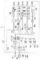
以下に説明する実施形態は、本発明を適用する建物として戸建て住宅の家屋を想定して説明するが、本発明の技術思想を集合住宅に適用することを妨げるものではない。建屋Hには、図3に示すように、直流電力を出力する直流電力供給部101と、直流電力により駆動される電気機器である直流機器102とが設けられ、直流電力供給部101の出力端部に接続した直流供給線路Wdcを通して直流機器102に直流電力が供給される。直流電力供給部101と直流機器102との間には、直流供給線路Wdcに流れる電流を監視し、異常を検知したときに直流給電線路Wdc上で直流電力供給部101から直流機器102への給電を制限ないし遮断する直流ブレーカ114が設けられる。(Embodiment 1)
The embodiments described below are described assuming a detached house as a building to which the present invention is applied, but this does not preclude the application of the technical idea of the present invention to an apartment house. As shown in FIG. 3, the building H is provided with a DC
直流供給線路Wdcは、直流電力の給電路であるとともに通信路としても兼用されており、高周波の搬送波を用いてデータを伝送する通信信号を直流電圧に重畳することにより直流供給線路Wdcに接続された機器間での通信を可能にしている。この技術は、交流電力を供給する電力線において交流電圧に通信信号を重畳させる電力線搬送技術と類似した技術である。 The DC supply line Wdc is used as both a DC power supply path and a communication path, and is connected to the DC supply line Wdc by superimposing a communication signal for transmitting data on a DC voltage using a high-frequency carrier wave. Enables communication between devices. This technique is similar to a power line carrier technique in which a communication signal is superimposed on an AC voltage in a power line that supplies AC power.
直流供給線路Wdcは、直流電力供給部101を介して宅内サーバ116に接続される。宅内サーバ116は、宅内の通信網(以下、「宅内網」という)を構築する主装置であり、宅内網において直流機器102が構築するサブシステムなどと通信を行う。 The DC supply line Wdc is connected to the
図示例では、サブシステムとして、パーソナルコンピュータ、無線アクセスポイント、ルータ、IP電話機のような情報系の直流機器102からなる情報機器システムK101、照明器具のような照明系の直流機器102からなる照明システムK102,K105、来客対応や侵入者の監視などを行う直流機器102からなるインターホンシステムK103、火災感知器のような警報系の直流機器102からなる住警器システムK104などがある。各サブシステムは、自立分散システムを構成しており、サブシステム単独でも動作が可能になっている。 In the example shown in the drawing, as an subsystem, an illumination system comprising an information equipment system K101 comprising an information-
上述した直流ブレーカ114は、サブシステムに関連付けて設けられており、図示例では、情報機器システムK101、照明システムK102、インターホンシステムK103および住警器システムK104、照明システムK105に関連付けて4個の直流ブレーカ114を設けている。1台の直流ブレーカ114に複数個のサブシステムを関連付ける場合には、サブシステムごとに直流供給線路Wdcの系統を分割する接続ボックス121が設けられる。図示例においては、インターホンシステムK103と住警器システムK104の間に接続ボックス121が設けられている。 The
情報機器システムK101としては、壁コンセントあるいは床コンセントの形態で建屋Hに先行配置(建屋Hの建築時に施工)される直流コンセント131に接続される直流機器102からなる情報機器システムK101が設けられる。 As the information equipment system K101, there is provided an information equipment system K101 composed of a
照明システムK102、K105としては、建屋Hに先行配置される照明器具(直流機器102)からなる照明システムK102と、天井に先行配置される引掛シーリング132に接続する照明器具(直流機器102)からなる照明システムK105とが設けられる。引掛シーリング132には、建屋Hの内装施工時に施工業者が照明器具を取り付けるか、または家人自身が照明器具を取り付ける。 The lighting systems K102 and K105 include a lighting system K102 including a lighting device (DC device 102) arranged in advance in the building H and a lighting device (DC device 102) connected to a
照明システムK102を構成する直流機器102である照明器具に対する制御の指示は、赤外線リモコン装置を用いて与えるほか、直流供給線路Wdcに接続されたスイッチ141から通信信号を用いて与えることができる。すなわち、スイッチ141は直流機器102とともに通信の機能を有している。また、スイッチ141の操作によらず、宅内網の別の直流機器102あるいは宅内サーバ116から通信信号により制御の指示がなされることもある。照明器具への指示には、点灯、消灯、調光、点滅点灯などがある。 In addition to using an infrared remote control device, a control instruction for the lighting apparatus that is the
上述した直流コンセント131、引掛シーリング132には、任意の直流機器102を接続することができ、接続された直流機器102に直流電力を出力するから、以下では直流コンセント131、引掛シーリング132を区別する必要がない場合には「直流アウトレット」と呼ぶ。 Since any
これらの直流アウトレットは、直流機器102に直接設けた接触子(図示しないプラグの栓刃や導体片等)または接続線を介して設けた接触子が差し込まれる差込式の接続口が器体に開口し、接続口に差し込まれた接触子に直接接触する接触子受けが器体に保持された構造を有しており、接触式で給電を行う。直流アウトレットに接続された直流機器102が通信機能を有する場合には、直流供給線路Wdcを通して通信信号を伝送することが可能になる。直流機器102だけではなく直流アウトレットにも通信機能が設けられている。 These DC outlets have contacts on the DC device 102 (plug blades, conductor pieces, etc., not shown) or plug-in connection ports into which contacts provided via connecting wires are inserted. It has a structure in which a contact receiver that is open and directly contacts the contact inserted into the connection port is held by the container, and supplies power in a contact manner. When the
宅内サーバ116は、宅内網に接続されるだけではなく、インターネットを構築する広域網NTに接続される接続口を有している。宅内サーバ116が広域網NTに接続されている場合には、広域網NTに接続されたコンピュータサーバであるセンタサーバ200によるサービスを享受することができる。 The
センタサーバ200が提供するサービスには、広域網NTを通して宅内網に接続された機器(主として直流機器102であるが通信機能を有した他の機器も含む)の監視や制御を可能にするサービスがある。このサービスにより、パーソナルコンピュータ、インターネットTV、移動体電話機などのブラウザ機能を備える通信端末(図示せず)を用いて宅内網に接続された機器の監視や制御が可能になる。 The service provided by the
宅内サーバ116は、広域網NTに接続されたセンタサーバ200との間の通信と、宅内網に接続された機器との間の通信との両方の機能を備え、宅内網の機器に関する識別情報(ここでは、IPアドレスを用いるものとする)の取得の機能を備える。 The in-
宅内サーバ116は、センタサーバ200との通信機能を用いることにより、広域網NTに接続された通信端末からセンタサーバ200を通して宅内の機器の監視や制御を可能にする。センタサーバ200は、宅内の機器と広域網NT上の通信端末とを仲介する。 The
通信端末から宅内の機器の監視や制御を行う場合は、監視や制御の要求をセンタサーバ200に記憶させ、宅内の機器は定期的に片方向のポーリング通信を行うことにより、通信端末からの監視や制御の要求を受信する。この動作により、通信端末から宅内の機器の監視や制御が可能になる。 When monitoring and controlling home devices from a communication terminal, monitoring and control requests are stored in the
また、宅内の機器において火災検知など通信端末に通知すべきイベントが生じたときには、宅内の機器からセンタサーバ200に通知し、センタサーバ200から通信端末に対して電子メールによる通知を行う。 Further, when an event that should be notified to the communication terminal, such as a fire detection, occurs in the home device, the home device notifies the
宅内サーバ116における宅内網との通信機能のうち重要な機能は、宅内網を構成する機器の検出と管理である。宅内サーバ116では、UPnP(Universal Plug and Play)を応用して宅内網に接続された機器を自動的に検出する。宅内サーバ116はブラウザ機能を有する表示器117を備え、検出した機器の一覧を表示器117に表示する。この表示器117はタッチパネル式もしくは操作部が付設された構成を有し、表示器117の画面に表示された選択肢から所望の内容を選択する操作が可能になっている。したがって、宅内サーバ116の利用者(施工業者あるいは家人)は、表示器117の画面上で機器の監視ないし制御が可能になる。表示器117は宅内サーバ116とは分離して設けてもよい。 An important function among the communication functions with the home network in the
宅内サーバ116では、機器の接続に関する情報を管理しており、宅内網に接続された機器の種類や機能とアドレスとを把握する。したがって、宅内網の機器を連動動作させることができる。機器の接続に関する情報は上述のように自動的に検出されるが、機器を連動動作させるには、機器自身が保有する属性により自動的に関係付けを行うほか、宅内サーバ116にパーソナルコンピュータのような情報端末を接続し、情報端末のブラウザ機能を利用して機器の関係付けを行うこともできる。 The in-
機器の連動動作の関係は各機器がそれぞれ保持する。したがって、機器は宅内サーバ116を通すことなく連動動作することができる。各機器について、連動動作の関係付けを行うことにより、たとえば、機器であるスイッチの操作により、機器である照明器具の点灯あるいは消灯の動作を行うことが可能になる。また、連動動作の関係付けはサブシステム内で行うことが多いが、サブシステムを超える関係付けも可能である。 Each device holds the relationship of the interlocking operation of the devices. Therefore, the device can operate in an interlocked manner without passing through the
ところで、直流電力供給部101は、基本的には、商用電源のように宅外から供給される交流電源ACの電力変換により直流電力を生成する。図示する構成では、交流電源ACは、分電盤110に内器として取り付けられた主幹ブレーカ111を通して、スイッチング電源を含むAC/DCコンバータ112に入力される。AC/DCコンバータ112から出力される直流電力は、協調制御部113を通して各直流ブレーカ114に接続される。 By the way, the DC
直流電力供給部101には、交流電源ACから電力が供給されない期間(たとえば、商用電源ACの停電期間)に備えて二次電池162が設けられている。また、直流電力を生成する太陽電池161や燃料電池163を併用することも可能になっている。交流電源ACから直流電力を生成するAC/DCコンバータ112を備える主電源(第1の電源)に対して、太陽電池161や二次電池162や燃料電池163は分散電源(第2の電源)になる。なお、図示例において、太陽電池161、二次電池162、燃料電池163は出力電圧を制御する回路部を含み、二次電池162は放電だけではなく充電を制御する回路部も含んでいる。 The DC
分散電源のうち太陽電池161や燃料電池163は必ずしも設けなくてもよいが、二次電池162は必ず設けられる。二次電池162は主電源や他の分散電源により適時充電され、二次電池162の放電は、交流電源ACから電力が供給されない期間だけではなく必要に応じて適時に行われる。二次電池162の充放電や主電源と分散電源との協調は、協調制御部113により行われる。すなわち、協調制御部113は、直流電力供給部101を構成する主電源および分散電源から直流機器102への電力の配分を制御する直流電力制御部として機能する。なお、太陽電池161、二次電池162、燃料電池163の出力を交流電力に変換し、AC/DCコンバータ112の入力電力として用いる構成を採用してもよい。 Of the distributed power sources, the
直流機器102の駆動電圧は機器に応じた複数種類の電圧から選択されるから、協調制御部113にDC/DCコンバータを設け、主電源および分散電源から得られる直流電圧を必要な電圧に変換するのが望ましい。通常は、1系統のサブシステム(もしくは1台の直流ブレーカ114に接続された直流機器102)に対して1種類の電圧が供給されるが、1系統のサブシステムに対して3線以上を用いて複数種類の電圧を供給するように構成してもよい。あるいはまた、直流供給線路Wdcを2線式とし、線間に印加する電圧を時間経過に伴って変化させる構成を採用することも可能である。DC/DCコンバータは、直流ブレーカと同様に複数に分散して設けてもよい。 Since the driving voltage of the
上述の構成例では、AC/DCコンバータ112を1個だけ図示しているが、複数個のAC/DCコンバータ112を並設することが可能であり、複数個のAC/DCコンバータ112を設けるときには、負荷の大きさに応じて運転するAC/DCコンバータ112の台数を増減させるのが望ましい。 In the above configuration example, only one AC /
上述したAC/DCコンバータ112、協調制御部113、直流ブレーカ114、太陽電池161、二次電池162、燃料電池163には通信機能が設けられており、主電源および分散電源や直流機器102を含む負荷の状態に対処する連携動作を行うことを可能にしている。この通信に用いる通信信号は、直流機器102に用いる通信信号と同様に直流電圧に重畳する形式で伝送する。 The AC /
上述の例では主幹ブレーカ111から出力された交流電力をAC/DCコンバータ112により直流電力に変換するために、AC/DCコンバータ112を分電盤110内に配置しているが、主幹ブレーカ111の出力側において分電盤110内に設けた分岐ブレーカ(図示せず)で交流供給線路を複数系統に分岐し、各系統の交流供給線路にAC/DCコンバータを設けて系統ごとに直流電力に変換する構成を採用してもよい。 In the above example, the AC /
この場合、建屋Hの各階や各部屋を単位としてAC/DCコンバータを設けることができるから、AC/DCコンバータを系統別に管理することができ、しかも、直流電力を利用する直流機器102との間の直流供給線路Wdcの距離が小さくなるから、直流供給線路Wdcでの電圧降下による電力損失を低減させることができる。また、主幹ブレーカ111および分岐ブレーカを分電盤110に収納し、AC/DCコンバータ112と協調制御部113と直流ブレーカ114と宅内サーバ116とを分電盤110とは別の盤に収納してもよい。 In this case, since the AC / DC converter can be provided for each floor or room of the building H, the AC / DC converter can be managed for each system, and between the
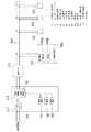
そして、本実施形態の配電システムは、図1、図3に示すように、協調制御部113内に停電検知部118を配置しており、停電検知部118は、商用電源ACの停電を検知すると(すなわち、AC/DCコンバータ112の出力が停止すると)、協調制御部113に対して、直流供給線路Wdcを介して供給される直流機器102への電力の配分として、太陽電池161、二次電池162、燃料電池163からの出力を100%、AC/DCコンバータ112からの出力を0%にして、分散電源からの100%供給に切り換えるように指示する。さらに、停電検知部118は、停電検知信号を直流供給線路Wdcの直流電圧に重畳して、直流ブレーカ114を介して全ての直流機器102へ送信する。 And the power distribution system of this embodiment has arrange | positioned the power
直流機器102は、機能部102a、通信部102b、省電力制御部102cを備える。 The
機能部102aは、各直流機器102が有する機能(例えば、インターホン機能、カメラ機能、照明機能、空調機能、センサ機能、通信機能、スピーカ機能、LANのハブ機能、暖房機能等)を構成しており、通常は、動作指示に基づいて各機能が実行される通常モードで動作している。この動作指示は、直流機器102に設けたスイッチ(図示なし)の操作や、赤外線等のリモコン装置(図示なし)からのリモコン信号や、宅内網の別の直流機器102あるいは宅内サーバ116から受信した通信信号によって発生する。 The
通信部102bは、直流供給線路Wdcの直流電圧に信号を重畳させたり、直流供給線路Wdcの直流電圧に重畳している信号を復調することで、直流供給線路Wdcを介して電源重畳多重伝送を行うものであり、停電検知部118からの停電検知信号を受信する。 The
省電力制御部102cは、停電検知信号を受信すると、図示しないメモリ内に予め設定されたプログラムに基づいて、機能部102aを、消費電力が低減する方向へ負荷を動作させる省電力モードに切り換えて動作させる。 Upon receiving the power failure detection signal, the power saving
以下、省電力モードにおける各直流機器102の動作について説明する。 Hereinafter, the operation of each
まず、図2に示すように、インターホンシステムK103においては、来客対応や侵入者の監視などを行う直流機器102として、建屋H内に設置したインターホン親機1021、建屋Hの玄関外に設置したドアホン子器1022、建屋H外の庭等の敷地内に設置したセンサライト付きカメラ子器1023、玄関等の出入口を開閉するドアに設けられた電気錠1024、建屋Hの玄関外に設置して電気錠1024の開錠動作を行う際に必要な認証を行う非接触式キーリーダー1025とを備え、住警器システムK104においては、建屋H内に設置して火災検知を行う複数の火災警報器(火災センサ)1026を備えており、インターホンシステムK103および住警器システムK104で、来客対応機能、防犯機能、防災機能を有している。 First, as shown in FIG. 2, in the intercom system K103, the
そして、来客対応機能としては、屋内のインターホン親機1021と屋外のドアホン子器1022との間で通話可能に構成されており、家人と来客との間で通話できるとともに、ドアホン子器1022に設けたカメラ1022aによって撮像された来客の映像データをインターホン親機1021に送信し、インターホン親機1021では、受け取った撮像データを表示画面1021aに表示して来客の姿をモニタしながら通話が可能となる。 And as a function corresponding to a visitor, it is configured so that a call can be made between an indoor
また、家人は認証情報を格納したICカードCDを携行しており、玄関等の出入口から建屋H内に入る際には、ICカードCDを非接触式キーリーダー1025に近づけることで、マイクロ波等を用いた通信によって非接触式キーリーダー1025がICカードCD内の認証情報を取得し、取得した認証情報が予め記憶しているいずれかの認証情報と一致すれば、非接触式キーリーダー1025から電気錠1024へ錠開信号が送信され、電気錠1024は開錠する。通常モードでは、非接触式キーリーダー1025の電源は常に直流供給線路Wdcから供給されており、家人はICカードCDを非接触式キーリーダー1025に近づけるだけで認証情報の取得処理が行われる。 Also, the family member carries an IC card CD storing authentication information, and when entering the building H from the entrance / exit of the entrance or the like, the IC card CD is brought close to the non-contact
また、防犯機能としては、カメラ子器1023は人感センサ1023aおよびライト1023bを具備しており、人感センサ1023aが敷地内への侵入者を検知すると、ライト1023bを点灯させるとともにカメラ1023cで撮像した敷地内の撮像データをインターホン親機1021へ送信する。インターホン親機1021は、受け取った撮像データを表示画面1021aに表示することで、侵入者の監視が可能となる。 As a security function, the
さらに、防災機能としては、いずれかの火災警報器1026が火災を検知した場合に火災報知として警報音を鳴動させるとともに、インターホン親機1021および他の火災警報器1026に火災検知信号を送信し、インターホン親機1021および他の火災警報器1026も火災報知として警報音を連動して鳴動させる。 Further, as a disaster prevention function, when any of the
このようなインターホンシステムK103および住警器システムK104では、省電力モードに切り換わると、カメラ子器1023は撮像動作を停止し、インターホン親機1021は、ドアホン子器1022との通話機能およびモニタ機能を停止して、火災警報器1026からの火災検知信号のみを受け付けて、火災報知のみを行う。火災警報器1026は、通常モードと同様に火災検知、火災報知を行う。したがって、商用電源ACの停電時に、インターホンによる通話処理やモニタ処理を停止し、火災警報器1026による監視・報知処理のみを行うことで、防災上必要な監視・報知処理を長時間動作させることができる。 In such an intercom system K103 and the residential security system K104, when the mode is switched to the power saving mode, the
また、住警器システムK104に、防犯用の警報器を設け、省電力モードでは上記火災警報器1026と同様に動作させることで、防犯上必要な監視・報知処理を長時間動作させることができる。 Moreover, the alarm device for crime prevention is provided in the residence alarm system K104, and the monitoring / notification processing necessary for crime prevention can be operated for a long time by operating in the same manner as the
さらに、非接触式キーリーダー1025は、内部に設けた接点(図示無し)がオフすることで、直流供給線路Wdcからの電源供給を停止させて、認証情報の取得処理は行われず、本体に設けた押ボタンスイッチ1025aを押下したときのみ、上記接点がオンして直流供給線路Wdcから電源を供給され、認証情報の取得処理が行われる。したがって、商用電源ACの停電時に、非接触式キーリーダー1025への電力供給を手動で行うことで、防犯上必要な認証処理を長時間動作させることができる。 Further, the non-contact type
なお、インターホンシステムK103および住警器システムK104における省電力モード時の上記動作は一例であり、インターホン親機1021は、省電力モード時の動作としてドアホン子器1022との通話機能のみを行い、火災警報器1026は火災検知時に警報音を鳴動させるが、インターホン親機1021および他の火災警報器1026には火災検知信号を送信しない構成でもよい。 Note that the above operation in the power saving mode in the intercom system K103 and the residential alarm system K104 is an example, and the
次に、情報機器システムK101において、パーソナルコンピュータ、無線アクセスポイント、ルータ、IP電話機のような情報系の直流機器102は、省電力モードに切り換わると、現在の情報処理を完了させて必要なデータを保存した後、動作を停止する。 Next, in the information device system K101, when the information-
次に、照明システムK102,K105において、照明器具のような照明系の直流機器102は、省電力モードに切り換わると、調光レベルを下げて点灯する。または、最小限必要な照明器具のみを調光レベルを下げて点灯し、他の照明器具は消灯させる。 Next, in the lighting systems K102 and K105, when the
したがって、商用電源ACの停電時には、停電検知部118から全直流機器102に対して停電検知信号を送信し、各直流機器102では、動作指示に基づいて各機能が実行される通常モードから、消費電力が低減する方向へ負荷を動作させる省電力モードに切り換わるので、バックアップ電源である太陽電池161、二次電池162、燃料電池163の負担も軽くなり、停電後においても長時間の直流機器102の動作が可能となる。 Therefore, at the time of a power failure of the commercial power supply AC, a power failure detection signal is transmitted from the power
また、上記直流機器102の省電力モードでの動作は、各直流機器102の省電力制御部102cに格納されているプログラムで設定されるので、各直流機器102の使い方や稼働状況等に応じた最適な動作とすることができ、さらには変更も容易となる。 The operation of the
なお、交流配電系統に本実施形態と同様の構成を適用してもよい。この場合、太陽電池161、二次電池162、燃料電池163の出力を交流電力に変換するDC/ACコンバータが設けられ、協調制御部113の入力には、商用電源ACとDC/ACコンバータとが接続される。 In addition, you may apply the structure similar to this embodiment to an alternating current power distribution system. In this case, a DC / AC converter that converts the output of the
101 直流電力供給部
112 AC/DCコンバータ
113 協調制御部
118 停電検知部
161 太陽電池
162 二次電池
163 燃料電池
102 直流機器
102a 機能部
102b 通信部
102c 省電力制御部
Wdc 直流供給線路
AC 商用電源DESCRIPTION OF
Claims (4)
Translated fromJapanese電力供給手段の出力から配設された電力供給線路と、
電力供給線路を介して電力供給手段から電力を供給され、電力供給線路を介して受信した信号に基づいて動作する負荷と、
商用電源の停電を検知すると電力供給線路を介して停電検知信号を送信する停電検知手段と、
を備え、
協調制御手段は、停電検知手段が停電を検知した場合、第2の電源のみから電力供給線路を介して負荷へ電力を供給し、電力供給線路を介して停電検知信号を受信した負荷は、消費電力が低減する方向へ動作する
ことを特徴とする配電システム。A first power source that uses a commercial power source, a second power source that uses a battery as a source, and a power supply unit that includes a cooperative control unit that controls the distribution of each power supplied by the first and second power sources; ,
A power supply line arranged from the output of the power supply means;
A load that is supplied with power from the power supply means via the power supply line and operates based on a signal received via the power supply line;
A power failure detection means that transmits a power failure detection signal via a power supply line when a commercial power failure is detected,
With
When the power failure detection means detects a power failure, the cooperative control means supplies power from the second power source only to the load via the power supply line, and the load that receives the power failure detection signal via the power supply line is consumed. A power distribution system that operates in a direction that reduces power.
各負荷が電力供給線路を介して停電検知信号を受信した場合、カメラ子器は、撮像動作を停止し、インターホン親機は、ドアホン子器との通話動作を停止してセンサの検知結果に基づく報知のみを行うことを特徴とする請求項1記載の配電システム。The load includes an interphone master unit with a monitor function and a door phone slave unit with a camera function that communicate with each other, a camera slave unit that transmits imaging data to the interphone master unit, and a detection result by detecting the state of a person or an object. It is composed of a sensor that transmits to the base unit, and at least the intercom base unit performs notification based on the detection result of the sensor,
When each load receives a power failure detection signal via the power supply line, the camera sub unit stops the imaging operation, and the interphone base unit stops the call operation with the door phone sub unit and is based on the detection result of the sensor. The power distribution system according to claim 1, wherein only the notification is performed.
認証手段は、電力供給線路を介して停電検知信号を受信した場合、ユーザによる操作手段の操作によって電力供給線路からの給電をオン・オフし、停電検知信号を受信していない場合、電力供給線路からの給電を常時オンしていることを特徴とする請求項1記載の配電システム。The load is provided on the authentication means for obtaining authentication information from the authentication information storage means carried by the user and authenticating by the user, and on the door for opening and closing a person's doorway. It consists of an electric lock that unlocks when it authenticates
When the authentication means receives the power failure detection signal via the power supply line, the power supply line is turned on / off by the operation of the operation means by the user and when the power failure detection signal is not received. The power distribution system according to claim 1, wherein power supply from is always on.
Priority Applications (1)
| Application Number | Priority Date | Filing Date | Title |
|---|---|---|---|
| JP2007332829AJP2009159678A (en) | 2007-12-25 | 2007-12-25 | Power distribution system |
Applications Claiming Priority (1)
| Application Number | Priority Date | Filing Date | Title |
|---|---|---|---|
| JP2007332829AJP2009159678A (en) | 2007-12-25 | 2007-12-25 | Power distribution system |
Publications (1)
| Publication Number | Publication Date |
|---|---|
| JP2009159678Atrue JP2009159678A (en) | 2009-07-16 |
Family
ID=40963081
Family Applications (1)
| Application Number | Title | Priority Date | Filing Date |
|---|---|---|---|
| JP2007332829APendingJP2009159678A (en) | 2007-12-25 | 2007-12-25 | Power distribution system |
Country Status (1)
| Country | Link |
|---|---|
| JP (1) | JP2009159678A (en) |
Cited By (7)
| Publication number | Priority date | Publication date | Assignee | Title |
|---|---|---|---|---|
| JP2011130644A (en)* | 2009-12-21 | 2011-06-30 | Panasonic Electric Works Co Ltd | Dc power distribution system |
| WO2012002530A1 (en)* | 2010-07-02 | 2012-01-05 | シャープ株式会社 | Dc-dc converter, method of controlling thereof, and dc power feeding system |
| CN104782014A (en)* | 2012-08-16 | 2015-07-15 | 罗伯特·博世有限公司 | DC building system with energy storage and control system |
| CN106099215A (en)* | 2015-04-30 | 2016-11-09 | 保时捷股份公司 | Battery system |
| JP2018136691A (en)* | 2017-02-21 | 2018-08-30 | 富士電機株式会社 | DC concentrated power supply system |
| WO2020129580A1 (en)* | 2018-12-21 | 2020-06-25 | パナソニックIpマネジメント株式会社 | Intercom vestibule device, intercom system, information terminal, reporting method, and program |
| JP2021057743A (en)* | 2019-09-30 | 2021-04-08 | 大和ハウス工業株式会社 | Sensor system |
Citations (10)
| Publication number | Priority date | Publication date | Assignee | Title |
|---|---|---|---|---|
| JPS63209437A (en)* | 1987-02-24 | 1988-08-31 | 松下電工株式会社 | Electric source backup system of central monitoring board |
| JPH03124233A (en)* | 1989-10-06 | 1991-05-27 | Fujitsu Ltd | Power supply with backup battery |
| JPH05207172A (en)* | 1992-01-29 | 1993-08-13 | Sharp Corp | Information transmission system |
| JP2000067334A (en)* | 1998-08-26 | 2000-03-03 | Matsushita Electric Works Ltd | Multiple dwelling housing fire alarm system |
| JP2003163666A (en)* | 2001-11-27 | 2003-06-06 | Matsushita Electric Works Ltd | Intercommunication system |
| JP2003244866A (en)* | 2002-02-15 | 2003-08-29 | Toshiba Corp | Power line carrier communication system, centralized control device, and controlled device |
| JP2004135197A (en)* | 2002-10-11 | 2004-04-30 | Matsushita Electric Works Ltd | Integrated control/monitor system for residence |
| JP2005042350A (en)* | 2003-07-25 | 2005-02-17 | Oki Electric Ind Co Ltd | Lock control system, lock controller and key device |
| JP2005236581A (en)* | 2004-02-18 | 2005-09-02 | Matsushita Electric Works Ltd | Monitoring/calling system for apartment house |
| JP2007146586A (en)* | 2005-11-30 | 2007-06-14 | Alpha Corp | Electric lock controller |
- 2007
- 2007-12-25JPJP2007332829Apatent/JP2009159678A/enactivePending
Patent Citations (10)
| Publication number | Priority date | Publication date | Assignee | Title |
|---|---|---|---|---|
| JPS63209437A (en)* | 1987-02-24 | 1988-08-31 | 松下電工株式会社 | Electric source backup system of central monitoring board |
| JPH03124233A (en)* | 1989-10-06 | 1991-05-27 | Fujitsu Ltd | Power supply with backup battery |
| JPH05207172A (en)* | 1992-01-29 | 1993-08-13 | Sharp Corp | Information transmission system |
| JP2000067334A (en)* | 1998-08-26 | 2000-03-03 | Matsushita Electric Works Ltd | Multiple dwelling housing fire alarm system |
| JP2003163666A (en)* | 2001-11-27 | 2003-06-06 | Matsushita Electric Works Ltd | Intercommunication system |
| JP2003244866A (en)* | 2002-02-15 | 2003-08-29 | Toshiba Corp | Power line carrier communication system, centralized control device, and controlled device |
| JP2004135197A (en)* | 2002-10-11 | 2004-04-30 | Matsushita Electric Works Ltd | Integrated control/monitor system for residence |
| JP2005042350A (en)* | 2003-07-25 | 2005-02-17 | Oki Electric Ind Co Ltd | Lock control system, lock controller and key device |
| JP2005236581A (en)* | 2004-02-18 | 2005-09-02 | Matsushita Electric Works Ltd | Monitoring/calling system for apartment house |
| JP2007146586A (en)* | 2005-11-30 | 2007-06-14 | Alpha Corp | Electric lock controller |
Cited By (11)
| Publication number | Priority date | Publication date | Assignee | Title |
|---|---|---|---|---|
| JP2011130644A (en)* | 2009-12-21 | 2011-06-30 | Panasonic Electric Works Co Ltd | Dc power distribution system |
| WO2012002530A1 (en)* | 2010-07-02 | 2012-01-05 | シャープ株式会社 | Dc-dc converter, method of controlling thereof, and dc power feeding system |
| JP2012016203A (en)* | 2010-07-02 | 2012-01-19 | Sharp Corp | DC / DC converter, its control method, and DC power supply system |
| CN104782014A (en)* | 2012-08-16 | 2015-07-15 | 罗伯特·博世有限公司 | DC building system with energy storage and control system |
| JP2015525057A (en)* | 2012-08-16 | 2015-08-27 | ロベルト・ボッシュ・ゲゼルシャフト・ミト・ベシュレンクテル・ハフツングRobert Bosch Gmbh | DC building system with energy storage and control system |
| CN106099215A (en)* | 2015-04-30 | 2016-11-09 | 保时捷股份公司 | Battery system |
| JP2018136691A (en)* | 2017-02-21 | 2018-08-30 | 富士電機株式会社 | DC concentrated power supply system |
| JP7054991B2 (en) | 2017-02-21 | 2022-04-15 | 富士電機株式会社 | DC centralized power supply system |
| WO2020129580A1 (en)* | 2018-12-21 | 2020-06-25 | パナソニックIpマネジメント株式会社 | Intercom vestibule device, intercom system, information terminal, reporting method, and program |
| JP2021057743A (en)* | 2019-09-30 | 2021-04-08 | 大和ハウス工業株式会社 | Sensor system |
| JP7376301B2 (en) | 2019-09-30 | 2023-11-08 | 大和ハウス工業株式会社 | sensor system |
Similar Documents
| Publication | Publication Date | Title |
|---|---|---|
| KR100780601B1 (en) | Intelligent integrated automatic control device and method | |
| JP5204473B2 (en) | Power supply system | |
| JP2010040389A (en) | Wiring device, and feeding system using wiring device | |
| JP5027642B2 (en) | Lighting control system | |
| JP2009159678A (en) | Power distribution system | |
| JP2009148009A (en) | Power supply system | |
| WO2007072594A1 (en) | Information management providing system and method | |
| CN104635687A (en) | Digital intelligent home security alarm system | |
| JP2009153339A (en) | DC power distribution system | |
| JP2009153304A (en) | Power supply system | |
| RU2281614C1 (en) | Integrated multi-functional controlling and monitoring system | |
| CN106125698A (en) | Internet of things intelligent household burglary-resisting system | |
| JP4944755B2 (en) | Housing information system | |
| CN214480996U (en) | Conference room reservation system and device adaptive according to environmental information | |
| RU2257682C2 (en) | Multi-functional door buzzer device | |
| JP4966180B2 (en) | Power distribution system | |
| JP2009146779A (en) | DC connection device | |
| JP2009165251A (en) | DC power distribution system | |
| JP2009165250A (en) | DC power distribution system | |
| JP4981650B2 (en) | Power distribution system | |
| JP2009159780A (en) | Power distribution system | |
| JP2009177924A (en) | Power supply system and outlet used therefor | |
| JP5914816B2 (en) | Energy management system | |
| JP2009159728A (en) | DC power distribution system | |
| JP2009159732A (en) | DC power distribution system |
Legal Events
| Date | Code | Title | Description |
|---|---|---|---|
| A621 | Written request for application examination | Free format text:JAPANESE INTERMEDIATE CODE: A621 Effective date:20100623 | |
| RD04 | Notification of resignation of power of attorney | Free format text:JAPANESE INTERMEDIATE CODE: A7424 Effective date:20100812 | |
| A711 | Notification of change in applicant | Free format text:JAPANESE INTERMEDIATE CODE: A712 Effective date:20120112 | |
| A977 | Report on retrieval | Free format text:JAPANESE INTERMEDIATE CODE: A971007 Effective date:20120116 | |
| A131 | Notification of reasons for refusal | Free format text:JAPANESE INTERMEDIATE CODE: A131 Effective date:20120403 | |
| A521 | Written amendment | Free format text:JAPANESE INTERMEDIATE CODE: A523 Effective date:20120604 | |
| A131 | Notification of reasons for refusal | Free format text:JAPANESE INTERMEDIATE CODE: A131 Effective date:20121016 | |
| A02 | Decision of refusal | Free format text:JAPANESE INTERMEDIATE CODE: A02 Effective date:20130305 |