JP2009159469A - Imaging apparatus and its control method - Google Patents
Imaging apparatus and its control methodDownload PDFInfo
- Publication number
- JP2009159469A JP2009159469AJP2007337332AJP2007337332AJP2009159469AJP 2009159469 AJP2009159469 AJP 2009159469AJP 2007337332 AJP2007337332 AJP 2007337332AJP 2007337332 AJP2007337332 AJP 2007337332AJP 2009159469 AJP2009159469 AJP 2009159469A
- Authority
- JP
- Japan
- Prior art keywords
- unit
- signal
- imaging
- image signal
- optical path
- Prior art date
- Legal status (The legal status is an assumption and is not a legal conclusion. Google has not performed a legal analysis and makes no representation as to the accuracy of the status listed.)
- Withdrawn
Links
- 238000003384imaging methodMethods0.000titleclaimsabstractdescription100
- 238000000034methodMethods0.000titleclaimsdescription21
- 238000009792diffusion processMethods0.000claimsabstractdescription52
- 230000003287optical effectEffects0.000claimsabstractdescription35
- 238000001514detection methodMethods0.000claimsdescription9
- XLYOFNOQVPJJNP-UHFFFAOYSA-NwaterSubstancesOXLYOFNOQVPJJNP-UHFFFAOYSA-N0.000abstractdescription13
- 238000006243chemical reactionMethods0.000description10
- 230000006835compressionEffects0.000description10
- 238000007906compressionMethods0.000description10
- 230000006837decompressionEffects0.000description8
- 230000006870functionEffects0.000description7
- 238000005286illuminationMethods0.000description7
- 238000003780insertionMethods0.000description3
- 230000037431insertionEffects0.000description3
- 230000000295complement effectEffects0.000description2
- 239000004065semiconductorSubstances0.000description2
- 239000003086colorantSubstances0.000description1
- 230000002596correlated effectEffects0.000description1
- 230000000875corresponding effectEffects0.000description1
- 230000007613environmental effectEffects0.000description1
- 238000009434installationMethods0.000description1
- 239000004973liquid crystal related substanceSubstances0.000description1
- 239000011159matrix materialSubstances0.000description1
- 229910044991metal oxideInorganic materials0.000description1
- 150000004706metal oxidesChemical class0.000description1
- 238000005070samplingMethods0.000description1
Images


Landscapes
- Transforming Light Signals Into Electric Signals (AREA)
- Color Television Image Signal Generators (AREA)
- Processing Of Color Television Signals (AREA)
- Studio Devices (AREA)
Abstract
Description
Translated fromJapaneseこの発明は、撮像装置とその制御方法に関する。詳しくは、水中で撮像を行うときに自然な色再現の撮像画像を容易に得られるようにするものである。 The present invention relates to an imaging apparatus and a control method thereof. More specifically, a captured image with natural color reproduction can be easily obtained when imaging is performed underwater.
従来、ディジタルスチルカメラやビデオカメラ等の撮像装置では、照明光の色温度が異なる場合でも被写体の色を正しく再現できるように、ホワイトバランス調整が行われている。例えば特許文献1の発明では、自動的にホワイトバランスを調整し続ける自動ホワイトバランス機能と、ユーザの操作に応じてホワイトバランスを調整できるワンプシュホワイトバランス機能を設けることが開示されている。ワンプッシュホワイトバランス機能は、高輝度で無彩色の領域が画像に含まれるように撮像を行っているときにワンプッシュホワイトバランス操作を行い、この高輝度で無彩色の部分を積分した値から、色信号のバランスを検出してホワイトバランスの調整を行うものである。 Conventionally, in an imaging apparatus such as a digital still camera or a video camera, white balance adjustment is performed so that the color of a subject can be correctly reproduced even when the color temperature of illumination light is different. For example, the invention of
また、水中で撮像装置を用いて撮像を行う場合、太陽光の一部の成分が水によって吸収されてしまい、水中の被写体が青みを帯びた状態となる。このため、特許文献2の発明では、撮像時の環境に応じた適切な発光色で照明光を発光する可変色照明手段と、撮像時の環境情報を取得する環境情報取得手段を設けて、取得された環境情報に基づいて撮像装置が水中にあることを検出したとき、照明光の発光色を水中に入射する太陽光の補色に合致するよう制御することが行われている。 In addition, when imaging is performed using an imaging device underwater, some components of sunlight are absorbed by the water, and the underwater subject becomes bluish. For this reason, the invention of Patent Document 2 is provided with variable color illumination means for emitting illumination light with an appropriate emission color according to the environment at the time of imaging, and environment information acquisition means for acquiring environment information at the time of imaging. When it is detected that the imaging device is underwater based on the environmental information, control is performed so that the emission color of the illumination light matches the complementary color of sunlight that enters the water.
ところで、水中で撮像を行う場合、上述のように太陽光の一部の成分(低波長である赤成分等)が水によって吸収されたり、プランクトンからの反射光が生じることで、水中の光源は陸上の光源と大きく異なったものとなる。このため、特許文献1の発明の自動ホワイトバランス機能を働かせていても、光源の変化がホワイトバランス機能の追従可能範囲を超えてしまい、自然な色再現を行うことができなくなってしまう。また、ワンプシュホワイトバランス機能を用いるものとすれば、ホワイトバランスの調整が可能となるが、水中に無彩色の板等を持ち込んで、この無彩色の板が撮像されている状態でワンプッシュホワイトバランス操作を行わなければならない。また、無彩色の板が撮像されている状態とするために例えば手中で無彩色の板を固定する必要もある。したがって、簡単かつ容易にプッシュホワイトバランス機能を用いることもできない。 By the way, when imaging in water, as described above, a part of sunlight (red component having a low wavelength, etc.) is absorbed by water, or reflected light from plankton is generated. It is very different from the light source on land. For this reason, even if the automatic white balance function of the invention of
また、特許文献2の発明を用いるものとした場合、撮像時の環境に応じた適切な発光色で照明光を発光する可変色照明手段を設けて、照明光の色を環境情報に基づいて制御しなければならない。したがって、撮像装置が複雑になってしまう。 When the invention of Patent Document 2 is used, variable color illumination means for emitting illumination light with an appropriate emission color according to the environment at the time of imaging is provided, and the color of the illumination light is controlled based on the environment information. Must. Therefore, the imaging device becomes complicated.
そこで、この発明では、水中で撮像を行うときに自然な色再現の撮像画像を容易に得ることができる撮像装置とその制御方法を提供するものである。 Therefore, the present invention provides an imaging apparatus that can easily obtain a captured image with natural color reproduction when imaging in water and a control method therefor.
この発明の概念は、撮像画像の画像信号を生成する撮像部に入射される被写体光の光路上に挿脱可能に半透明の拡散板を設けておき、水中で撮像を行うときの位置変化が閾値を超えるとき、光源の変化が生じている場合があるとして、半透明の拡散板を光路上に挿入させて、このときの画像信号から色成分ごとのゲインを設定することにある。 The concept of the present invention is that a translucent diffuser plate is provided on the optical path of subject light incident on an imaging unit that generates an image signal of a captured image so that the position change when imaging is performed underwater. When the threshold value is exceeded, a change in the light source may occur, and a translucent diffusion plate is inserted on the optical path, and the gain for each color component is set from the image signal at this time.
この発明の撮像装置は、入射された被写体光を電気信号に変換することで画像信号を生成する撮像部と、画像信号の色成分ごとに設定されているゲインで画像信号の色成分ごとの信号レベルを調整するホワイトバランス調整部と、位置変化を判別するための判別情報を生成する情報生成部と、 撮像部に入射される被写体光の光路上に挿脱可能として設けられた半透明の拡散板と、動作モードが水中撮像モードとされている場合において、判別情報に基づいて判別した位置変化が閾値を超えているとき、光路上に拡散板を挿入して、このとき撮像部で生成された画像信号を用いて色成分ごとのゲインを設定する制御部を備えるものである。 The imaging device of the present invention includes an imaging unit that generates an image signal by converting incident subject light into an electrical signal, and a signal for each color component of the image signal with a gain set for each color component of the image signal. A white balance adjustment unit that adjusts the level, an information generation unit that generates discrimination information for discriminating a change in position, and a translucent diffusion that is detachable on the optical path of the subject light incident on the imaging unit When the position change determined based on the discriminating information exceeds the threshold when the plate and the operation mode are the underwater imaging mode, a diffuser plate is inserted on the optical path and generated at this time by the imaging unit And a control unit for setting a gain for each color component using the image signal.
また、撮像装置の制御方法は、入射された被写体光を電気信号に変換することで画像信号を生成する工程と、画像信号の色成分ごとに設定されているゲインで画像信号の色成分ごとの信号レベルを調整する工程と、位置変化を判別するための判別情報を生成する工程と、動作モードが水中撮像モードとされている場合において、判別情報に基づいて判別した位置変化が閾値を超えているとき、撮像部に入射される被写体光の光路上に半透明の拡散板を挿入して、このとき生成された画像信号を用いて色成分ごとのゲインを設定する工程を設けたものである。 Further, the control method of the imaging apparatus includes a step of generating an image signal by converting incident subject light into an electric signal, and a gain set for each color component of the image signal for each color component of the image signal. The step of adjusting the signal level, the step of generating discrimination information for discriminating the position change, and the position change determined based on the discrimination information exceed the threshold when the operation mode is the underwater imaging mode. A step of inserting a translucent diffuser plate on the optical path of the subject light incident on the imaging unit and setting a gain for each color component using the image signal generated at this time is provided. .
この発明においては、位置変化を判別するための判別情報として、撮像部で生成された画像信号を用いて光源の推定を行うことにより得られた推定結果や、圧力センサで生成されたセンサ信号、動き検出センサで生成されたセンサ信号が用いられる。ここで、位置変化が閾値を超えたとき、光路上に無彩色あるいは単一色の拡散板を挿入させる。例えば、拡散板を光路上に挿脱可能に駆動する拡散板駆動部を設けて、この拡散板駆動部に駆動信号を供給して光路上に拡散板を自動的に挿入させる。または、ユーザに対して指示を行う指示部を設けて、光路上に拡散板を設ける操作をユーザに行わせる指示を指示部で表示させる。このようにして拡散板が挿入された状態とされているときの画像信号を用いて色成分ごとのゲインが設定される。 In this invention, as discrimination information for discriminating a change in position, an estimation result obtained by estimating a light source using an image signal generated by an imaging unit, a sensor signal generated by a pressure sensor, A sensor signal generated by the motion detection sensor is used. Here, when the position change exceeds the threshold value, an achromatic or single color diffuser is inserted on the optical path. For example, a diffusing plate driving unit that removably drives the diffusing plate on the optical path is provided, and a driving signal is supplied to the diffusing plate driving unit to automatically insert the diffusing plate on the optical path. Alternatively, an instruction unit for instructing the user is provided, and an instruction for causing the user to perform an operation of providing a diffusion plate on the optical path is displayed on the instruction unit. In this way, the gain for each color component is set using the image signal when the diffusion plate is inserted.
この発明によれば、位置変化が閾値を超えたとき、撮像部に入射される被写体光の光路上に半透明の拡散板が挿入されて、このとき撮像部で生成された画像信号を用いて色成分ごとのゲインが設定される。このため、水中等に移動したときホワイトバランスのキャリブレーションを簡単に行うことが可能となり、特殊な光源の下でも自然な色再現の撮像画像を容易に得ることができる。 According to the present invention, when the position change exceeds the threshold value, the translucent diffuser is inserted on the optical path of the subject light incident on the imaging unit, and the image signal generated by the imaging unit at this time is used. Gain for each color component is set. For this reason, it is possible to easily perform white balance calibration when moving underwater or the like, and a captured image with natural color reproduction can be easily obtained even under a special light source.
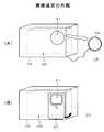
以下、図を参照しながら、この発明の実施の一形態について説明する。図1は撮像装置を用いた撮像装置10の外観を例示している。この撮像装置10は、水中で撮像を行うことができるようにしたものであり、撮像装置本体20を水中ハウジング(防水ケース)70に収納した構成とされている。また、撮像装置本体20または水中ハウジング70には、半透明の拡散板60が設けられている。 Hereinafter, an embodiment of the present invention will be described with reference to the drawings. FIG. 1 illustrates an appearance of an
拡散板60は、ホワイトバランスのキャリブレーションを行うときに、撮像装置本体20の撮像素子に入射される被写体光の光路上に挿入されて、拡散板60を透過した光を撮像素子に入射させるものである。したがって、拡散板60は、撮像装置本体20のレンズ部21に対向する水中ハウジング70の内面側または外面側に挿脱可能に設ける。また、拡散板60は撮像装置本体20のレンズ部21の前面側またはレンズ部21の後面側に設けるものとしてもよい。さらに、拡散板60の挿脱は自動あるいは手動のいずれであってもよい。なお、図1の(A)に示す撮像装置10では、水中ハウジング70の外面側に拡散板60を手動で装着、または装着されている拡散板60を手動で脱着する場合を例示している。 The
水中ハウジング70の外面側に手動で拡散板60を設ける場合、図1の(A)に示すように、拡散板60をレンズキャップ状に形成する。このように形成すれば、ホワイトバランスのキャリブレーションを行う際に、拡散板60が水中ハウジング70から簡単に脱落してしまうことを防止できる。また、容易に拡散板60を被写体光の光路上に挿入することができる。さらに、撮像装置本体20の動作が停止されているときレンズ部分を保護することも可能となる。 When the
図1の(B)に示す撮像装置10では、外面側あるいは内面側に拡散板60をスライド可能に設けるものとして、この拡散板60を撮像装置本体20からの駆動信号によって駆動する場合を例示している。 In the
水中ハウジング70の外面側あるいは内面側に拡散板60をスライド可能に設ける場合、ホワイトバランスのキャリブレーションを行うとき、拡散板60を撮像装置本体20のレンズ部21の前面側にスライドさせることで、拡散板60を被写体光の光路上に挿入する。この場合、拡散板60をレンズキャップ状に形成する方法に比べて、速やかに拡散板60を被写体光の光路上に挿入できる。 When the
図2は、撮像装置本体20の構成を示している。なお、図2に示す撮像装置本体20は、被写体光の光路上への拡散板60の挿脱を、レンズ部21の前面側で自動的に行う場合の構成を提示している。 FIG. 2 shows a configuration of the imaging apparatus
レンズ部21は、被写体光を撮像部22における撮像素子221の撮像面上に収束させるためのものである。また、レンズ部21は、撮像面上に形成される被写体像の大きさを調整するズーム動作等も行う。 The
撮像部22の撮像素子221は、固体撮像素子例えばCMOS(Complementary Metal Oxide Semiconductor)やCCD(Charge Coupled Device)のイメージセンサが用いられている。撮像素子221は、入射された被写体光を光電変換によって電気信号に変換して、得られた三原色信号を撮像画像の画像信号としてアナログ信号処理部222に供給する。アナログ信号処理部222は、例えば相関二重サンプリング回路やAGC回路を用いて構成されており、画像信号のノイズ除去や信号レベル調整を行ってA/D変換部223に供給する。A/D変換部223は、アナログ信号処理部222から供給された画像信号をディジタルの画像信号DVaに変換して、ホワイトバランス調整部23と制御部51に供給する。 As the
ホワイトバランス調整部23は、後述する制御部51によって設定されたゲインで画像信号DVaの色成分ごとの信号レベルを調整して、調整後の画像信号DVbをガンマ補正部24に供給する。例えば制御部51によって、赤色成分がゲインMR、緑色成分がゲインMG,青色成分がゲインMBに設定されているとき、ホワイトバランス調整部23は、撮像部22から供給された画像信号DVaの各色信号DVaR,DVaG,DVaBに対して、式(1)に示すようにゲインMR,MG(=1),MBを乗算して信号レベルを調整する。さらに、ホワイトバランス調整部23は、信号レベル調整後の各色信号DVbR,DVbG,DVbBを画像信号DVbとしてガンマ補正部24に供給する。 DVbR=MR×DVaR,DVbG=1×DVaB,DVbB=MB×DVaB ・・・(1) The white balance adjustment unit 23 adjusts the signal level for each color component of the image signal DVa with a gain set by the control unit 51 described later, and supplies the adjusted image signal DVb to the
ガンマ補正部24は、画像信号DVbを用いてガンマ補正処理を行い、補正後の画像信号DVcを信号変換部25に供給する。信号変換部25は、所望の形式の画像信号に変換する。例えば、信号変換部25は、三原色の画像信号DVcを輝度信号DYと色差信号D(R-Y),D(B-Y)に変換して、得られた輝度信号DYを圧縮伸長部31に供給する。また、信号変換部25は、得られた色差信号D(R-Y),D(B-Y)を色差信号補正部26に供給する。 The
色差信号補正部26は、ホワイトバランス調整部23で用いられるゲインMR,MG(=1),MBが明らかとなっていることから、この結果を用いて色差信号D(R-Y),D(B-Y)に対して色補正マトリクスにより色再現の補正を行ってから圧縮伸長部31に供給する。 Since the color difference
圧縮伸長部31は、輝度信号DYと色差信号D(R-Y),D(B-Y)を用いて符号化処理を行い、得られた符号化データDWを記録再生部32に供給する。また、圧縮伸長部31は、記録再生部32から供給された符号化データDRの復号化処理を行い、得られた例えば輝度信号DYdと色差信号D(R-Y)d,D(B-Y)dを表示部33に供給する。この圧縮伸長部31では、例えばJPEG方式やMPEG方式の符号化処理や復号化処理を行う。 The compression /
記録再生部32は、記録媒体例えば半導体メモリや光ディスク、磁気ディスク等に、圧縮伸長部31から供給された符号化データDWを書き込む。また、記録再生部32は、記録媒体に記録されている符号化データの読み出しを行い、読み出した符号化データDRを圧縮伸長部31に供給する。 The recording / reproducing
表示部33は、表示素子例えば液晶表示素子や有機EL表示素子と、表示素子を駆動する表示駆動部等で構成されている。表示部33は、信号変換部25で生成された輝度信号DYと色差信号D(R-Y),D(B-Y)を用いて撮像画像の表示を行う。また、表示部33は、圧縮伸長部31で復号化処理を行うことにより得られた輝度信号DYdと色差信号D(R-Y)d,D(B-Y)dを用いて再生画像の表示を行う。また、制御部51からの表示制御信号HSに基づき、種々のメニュー表示や、ユーザに対する指示を文字や図形で示したユーザ指示表示等を行う。 The
拡散板駆動部41は、無彩色あるいは所望の単一色である半透明の拡散板60と接続されている。拡散板駆動部41は、制御部51からの駆動信号FDに基づき拡散板60を駆動して、拡散板60を被写体光の光路上に挿入または離脱させる。 The diffusing plate driving unit 41 is connected to a
発光制御部42は、発光部43が接続されている。発光制御部42は、制御部51からの発光制御部LDに基づき発光部43を駆動して、所望の明るさの撮像画像が得られるように、被写体の照明を行う。 The light
情報生成部45は、位置変化を判別するための判別情報JGを生成する。情報生成部45は、撮像装置本体20が用いられている位置の情報や、被写体を照らしている光源の変化を示す情報を、位置変化を判別するための判別情報として生成する。 The information generation unit 45 generates discrimination information JG for discriminating a change in position. The information generation unit 45 generates information on the position where the imaging apparatus
情報生成部45は、光源の変化を示す情報を生成する場合、撮像部22で得られた画像信号DVaを用いて光源の推定を行い、推定結果を判別情報JGとする。情報生成部45は、例えば画像信号DVaの色信号ごとに全画素の信号レベルから平均値を算出して、色信号ごとの平均値を光源の推定結果として用いる。このように判別情報JGを生成すると、陸上から水中に移動して撮像画像が青みがかった色となったとき、青色信号の平均値が大きくなる。したがって、後述する制御部51は、判別情報JGによって位置の移動を判別することが可能となる。 When generating information indicating a change in the light source, the information generation unit 45 estimates the light source using the image signal DVa obtained by the imaging unit 22, and sets the estimation result as the discrimination information JG. For example, the information generation unit 45 calculates an average value from the signal levels of all pixels for each color signal of the image signal DVa, and uses the average value for each color signal as a light source estimation result. When the discrimination information JG is generated in this way, the average value of the blue signal increases when the captured image moves to the water from the land and becomes a bluish color. Therefore, the control unit 51 described later can determine the movement of the position based on the determination information JG.
また、情報生成部45は、撮像装置本体20が用いられている位置の情報を生成する場合、圧力センサや動き検出センサ等で生成されたセンサ信号を判別情報JGとして用いる。このように圧力センサのセンサ信号を判別情報JGとすれば、例えば水中で撮像を行っているときの水深の変化に応じてセンサ信号の信号レベルが変化する。したがって、制御部51は、圧力センサのセンサ信号を利用して位置変化を判別することが可能となる。また、動き検出センサのセンサ信号を判別情報JGとすれば、センサ信号で撮像装置本体20の動きを検知できる。したがって、制御部51は、センサ信号に基づく動きの検知結果から位置変化を判別することが可能となる。 Further, when generating information on the position where the imaging apparatus
制御部51には、ユーザインタフェース部52が接続されている。ユーザインタフェース部52は、シャッターボタンや撮像装置本体20の設定切換等を行うための操作ダイヤル等で構成されており、ユーザ操作に応じた操作信号SSを生成して制御部51に供給する。 A
制御部51は、メモリ(図示せず)に記憶されているプログラムを読み出して実行することにより、撮像装置本体20の動作を開始させる。また、制御部51は、ユーザインタフェース部52から供給された操作信号SSに応じて制御信号CTを生成して各部に供給することで、ユーザ操作に応じて撮像装置本体20を動作させる。 The control unit 51 reads out and executes a program stored in a memory (not shown) to start the operation of the imaging apparatus
また、制御部51は、表示制御信号HSを表示部33に供給して、上述のように種々のメニュー表示や、ユーザに対する指示を文字や図形で示したユーザ指示表示等を表示部33で行わせる。 Further, the control unit 51 supplies the display control signal HS to the
さらに、制御部51は、撮像装置本体20の動作モードが水中で撮像を行う水中撮像モードとされている場合、情報生成部45から取得した判別情報JGと、既に情報生成部45から取得して記憶している判別情報JGmを用いて位置変化の変化量を算出する。また、制御部51は、算出した変化量に基づきホワイトバランスのキャリブレーションが必要であるか否かの判別を行い、ホワイトバランスのキャリブレーションが必要であると判別したとき、指示部例えば表示部33からユーザに対する指示を行って、または駆動信号FDを生成して拡散板駆動部41に供給することで拡散板の挿脱を自動的に行ってキャリブレーション処理を行う。 Furthermore, when the operation mode of the imaging apparatus
なお、図2に示す撮像装置本体20は、三原色信号を用いてホワイトバランス調整のゲイン設定を行うものとしたが、色差信号を用いてゲインの設定を行うものとしてもよい。例えば、制御部51は、拡散板60が光路上に挿入されているときの青色差信号(青信号−輝度信号)と赤色差信号(赤色信号−輝度信号)についてそれぞれの積分値を算出して、算出した積分値からゲインを算出するものとしてもよい。また、色成分ごとに設定されているゲインで三原色信号の信号レベルを調整するものとしたが、色差信号の信号レベルを調整してホワイトバランス調整を行うものとしてもよい。また、圧縮伸長部31や表示部33で用いる信号は、輝度信号と色差信号に限られるものではなく、三原色信号を用いるものとしてもよい。 Note that the imaging apparatus
また、撮像装置本体20は、動作モードとして水中撮像モードのみを有するものや、他の動作モード例えば地上での撮像を行う通常撮像モード等を有してモードの切り替えが可能とされているものであってもよい。ここで、モードの切り替えは、ユーザインタフェース部52からの操作信号SSに基づいて行うものとしてもよく、また圧力センサ等のセンサ信号に基づいて自動的に行うものとしてもよい。 The
次に、水中撮像モードとされている場合の動作について図3のフローチャートと図4の表示画像を用いて説明する。撮像装置本体20のユーザインタフェース部52でパワーオン操作が行われると、ステップST1で制御部51は、撮像装置本体20をパワーオン状態としてステップST2に進む。また、制御部51は、表示制御信号HSを表示部33に供給して、動作が開始されたことをユーザが識別可能とするための表示、例えば図4の(A)に例示する表示を行う。 Next, the operation in the underwater imaging mode will be described using the flowchart in FIG. 3 and the display image in FIG. When a power-on operation is performed in the
ステップST2で制御部51は、判別情報JGの取得を行う。制御部51は、情報生成部45から判別情報JGを取得してステップST3に進む。 In step ST2, the control unit 51 acquires the discrimination information JG. The control unit 51 acquires the discrimination information JG from the information generation unit 45 and proceeds to step ST3.
ステップST3で制御部51は、位置変化の変化量を算出する。制御部51は、ステップST2で取得した判別情報JGと既に記憶している判別情報JGmから、位置変化の変化量を算出してステップST4に進む。 In step ST3, the control unit 51 calculates the amount of change in position. The control unit 51 calculates the change amount of the position change from the discrimination information JG acquired in step ST2 and the discrimination information JGm already stored, and proceeds to step ST4.
制御部51は、判別情報JGとして光源の変化を示す情報が生成されている場合、例えば全画素の色信号ごとの平均値から光源が推定されているとき、既に記憶されている判別情報JGmで示された光源との色の差を変化量とする。具体的には、全画素の色信号ごとの平均値と判別情報JGmで示された平均値との違いや各色信号の割合の違い等から、光源の色の違いを示す変化量を生成する。 When the information indicating the change of the light source is generated as the discrimination information JG, for example, when the light source is estimated from the average value for each color signal of all pixels, the control unit 51 uses the discrimination information JGm already stored. The difference in color from the indicated light source is taken as the amount of change. Specifically, the amount of change indicating the difference in color of the light source is generated from the difference between the average value for each color signal of all pixels and the average value indicated by the discrimination information JGm, the difference in the ratio of each color signal, and the like.
制御部51は、判別情報JGとして圧力センサや動き検出センサからのセンサ信号が用いられる場合、センサ信号から変化量を決定する。ここで、圧力センサからのセンサ信号が用いられる場合、制御部51は、例えば取得した判別情報JGが示す信号レベルと既に記憶されている判別情報JGmで示された信号レベルとの差を変化量とする。また、動き検出センサからのセンサ信号が用いられる場合、制御部51は、例えば動き検出センサからのセンサ信号を用いて移動方向と移動距離を推定して、予め判別情報JGmの記憶処理を行うものとしたときの位置からの距離を変化量とする。 When the sensor signal from the pressure sensor or the motion detection sensor is used as the discrimination information JG, the control unit 51 determines the amount of change from the sensor signal. Here, when the sensor signal from the pressure sensor is used, the control unit 51 determines, for example, the difference between the signal level indicated by the acquired discrimination information JG and the signal level indicated by the discrimination information JGm already stored. And When the sensor signal from the motion detection sensor is used, the control unit 51 estimates the movement direction and the movement distance using the sensor signal from the motion detection sensor, for example, and performs the storage process of the discrimination information JGm in advance. The distance from the position is taken as the amount of change.
なお、制御部51は、判別情報JGmがないとき、位置変化の変化量を閾値よりも大きい変化量としてステップST4に進む。 When there is no discrimination information JGm, the control unit 51 sets the change amount of the position change to a change amount larger than the threshold value, and proceeds to step ST4.
ステップST4で制御部51は、位置変化の変化量が上述の閾値を超えているか否か判別する。制御部51は、変化量が閾値を超えていると判別したときステップST5に進み、閾値を超えていると判別されないときステップST9に進む。 In step ST4, the control unit 51 determines whether or not the change amount of the position change exceeds the above-described threshold value. When it is determined that the amount of change exceeds the threshold, the control unit 51 proceeds to step ST5, and when it is not determined that the change exceeds the threshold, the control unit 51 proceeds to step ST9.
ステップST5で制御部51は、拡散板60の挿入処理を行う。制御部51は、自動で拡散板60を被写体光の光路上に挿入する場合、駆動信号FDを拡散板駆動部41に供給して、拡散板60を被写体光の光路上に移動させてステップST6に進む。また、手動で拡散板60の挿入処理を行う場合、制御部51は、ユーザに対して、拡散板60を被写体光の光路上に挿入させる指示を行う。例えば制御部51は、表示制御信号HSを表示部33に供給して、表示部33の画面上に、拡散板60を水中ハウジング70に装着する旨の文字表示やアイコン表示を行う。さらに、制御部51は、拡散板60の装着が完了したことを示すユーザ操作が行われたとき、拡散板60を装着する旨の指示を終了してステップST6に進む。 In step ST5, the control unit 51 performs the insertion process of the
図4の(B)は、手動で拡散板60の挿入処理を行う場合の指示画像を例示しており、制御部51は、表示部33を制御して、拡散板60を装着させる旨の文字表示を行う。このような指示画像が表示されているとき、拡散板60の装着が完了したことを示すユーザ操作がユーザインタフェース部52で行われると、制御部51は、指示表示を終了してステップST6に進む。 FIG. 4B illustrates an instruction image when manually inserting the
ステップST6で制御部51はホワイトバランスキャリブレーション処理を行う。制御部51は、拡散板60を撮像しているときに撮像部22から出力された画像信号DVaの各色信号DVaR,DVaG,DVaBを用いて式(2)の演算を行い、全画素の積分値Riv,Giv,Bivを算出する。なお、式(2)において、「i」は水平方向の画素位置、「j」は垂直方向の画素位置を示している。 Riv=ΣDVaR(i,j)、Giv=ΣDVaG(i,j)、Biv=ΣDVaB(i,j) ・・・(2) In step ST6, the control unit 51 performs white balance calibration processing. The control unit 51 performs the calculation of Expression (2) using the color signals DVaR, DVaG, DVaB of the image signal DVa output from the imaging unit 22 when imaging the
次に、制御部51は、積分値Riv,Giv,Bivを用いて式(3)の演算を行い、各積分値の逆数に緑信号の積分値Givを乗算して色ごとのゲインMR,MG,MBを算出する。 MR=(Giv/Riv)、MG=(Giv/Giv)、MB=(Giv/Biv) ・・・(3) Next, the control unit 51 performs the calculation of Expression (3) using the integral values Riv, Giv, Biv, and multiplies the reciprocal of each integral value by the integral value Giv of the green signal, thereby gains MR, MG for each color. , MB is calculated. MR = (Giv / Riv), MG = (Giv / Giv), MB = (Giv / Biv) (3)
また、制御部51は、表示制御信号HSを表示部33に供給して、ホワイトバランスキャリブレーション処理が行われていることをユーザが識別可能とするための表示、例えば図4の(C)に例示する表示を行う。 Further, the control unit 51 supplies a display control signal HS to the
ステップST7で制御部51は、拡散板60の離脱処理を行う。制御部51は、自動で拡散板60を離脱させる場合、駆動信号FDを拡散板駆動部41に供給して、被写体光の光路上から拡散板60が取り除かれるように移動させてステップST8に進む。また、手動で拡散板60を離脱させる場合、制御部51は、ユーザに対して、拡散板60を離脱させる旨の指示を行う。例えば制御部51は、表示部33の画面上に、拡散板60を離脱させる旨の文字表示やアイコン表示を行う。さらに、制御部51は、拡散板60の離脱が完了したことを示すユーザ操作が行われたとき、拡散板60を離脱させる旨の指示を終了してステップST8に進む。 In step ST <b> 7, the control unit 51 performs the detachment process of the
図4の(D)は、手動で拡散板60の離脱処理を行う場合の指示画像を例示しており、制御部51は、表示部33を制御して、拡散板60を離脱させる旨の文字表示を行う。このような指示画像が表示されているとき、拡散板60の脱着が完了したことを示すユーザ操作がユーザインタフェース部52で行われると、制御部51は、指示表示を終了してステップST8に進む。 FIG. 4D illustrates an instruction image when manually performing the detachment process of the
ステップST8で制御部51は、ステップST3で取得した判別情報を保存してステップST9に進む。また、判別情報JGmが保存されているとき、制御部51は、ステップST3で取得した判別情報に保存されている判別情報JGmを更新する。 In step ST8, the control unit 51 stores the discrimination information acquired in step ST3, and proceeds to step ST9. Further, when the discrimination information JGm is stored, the control unit 51 updates the discrimination information JGm stored in the discrimination information acquired in step ST3.
ステップST9で制御部51は、撮像動作を開始してステップST10に進む。このとき、制御部51は、ステップST6で算出した色成分ごとのゲインMR,MG,MBをホワイトバランス調整部23に供給する。ホワイトバランス調整部23は、撮像部22から供給された画像信号DVbの各色信号にDVbR,DVbG,DVbBに対して、式(1)に示すようにゲインMR,MG,MBを乗算して各色信号の信号レベルを調整して画像信号DVbを生成する。このため、ホワイトバランス調整部23から出力される画像信号DVbは、被写体の色が正しく再現された画像信号となる。 In step ST9, the control unit 51 starts an imaging operation and proceeds to step ST10. At this time, the control unit 51 supplies the gains MR, MG, and MB for each color component calculated in step ST6 to the white balance adjustment unit 23. The white balance adjustment unit 23 multiplies each color signal of the image signal DVb supplied from the image pickup unit 22 by DVbR, DVbG, DVbB and gains MR, MG, MB as shown in Expression (1). Is adjusted to generate an image signal DVb. Therefore, the image signal DVb output from the white balance adjustment unit 23 is an image signal in which the color of the subject is correctly reproduced.
また、制御部51は、表示部33を制御して、信号変換部25で生成された輝度信号DYと色差信号D(R-Y),D(G-Y)、またはガンマ補正部24から出力された画像信号DVcに基づいた撮像画像を図4の(E)に示すように表示させる。 In addition, the control unit 51 controls the
ステップST10で制御部51は、パワーオフ操作が行われたか否か判別する。ここで、制御部51は、パワーオフ操作が行われたことを判別していないときステップST2に戻り、パワーオフ操作が行われたことを判別したときステップST11に進む。 In step ST10, the control unit 51 determines whether a power-off operation has been performed. Here, when it is not determined that the power-off operation has been performed, the control unit 51 returns to step ST2, and when it is determined that the power-off operation has been performed, the control unit 51 proceeds to step ST11.
ステップST11で制御部51は、撮像装置10をパワーオフ状態として動作を終了する。 In step ST11, the control unit 51 sets the
なお、水中撮像モードとされている場合の動作は、図3に示す場合に限られるものではない。例えばステップST3で判別情報を取得するときの時間間隔を長くする場合(例えば2分〜3分)、ステップST4で位置変化の変化量が閾値を超えていないときステップST8に進むものとしてもよい。この場合、判別情報が取得されてから次に判別情報が取得されるまでの期間中に生じた位置変化が閾値を超えるものであるとき、キャリブレーション処理を行うようにできる。 The operation in the underwater imaging mode is not limited to the case shown in FIG. For example, when the time interval for obtaining the discrimination information in step ST3 is increased (for example, 2 to 3 minutes), the process may advance to step ST8 when the change amount of the position change does not exceed the threshold value in step ST4. In this case, the calibration process can be performed when the position change that occurs during the period from when the discrimination information is acquired until the next time when the discrimination information is acquired exceeds the threshold value.
このように、撮像装置10では、撮像部に入射される被写体光の光路上に半透明の拡散板を挿脱可能に設けて、位置変化が閾値を超えたとき、拡散板を光路上に挿入してホワイトバランスキャリブレーション処理が行われる。また、ホワイトバランスキャリブレーション処理が終了したときは、拡散板を光路上から離脱させる処理が行われる。このため、例えば陸上から水中に移動したとき、拡散板を光路上に挿入してホワイトバランスキャリブレーション処理が行われることから、水中でも自然な色合いの撮像画像を得ることができる。 As described above, in the
また、深度が変化して光源の色味が変わるような場合、ホワイトバランスキャリブレーション処理が行われることから、常に自然な色合いの撮像画像を得ることができる。 Further, when the depth changes and the color of the light source changes, the white balance calibration process is performed, so that a captured image with a natural hue can always be obtained.
さらに、半透明な拡散板として無彩色例えば白色の拡散板を用いれば、白色の被写体が正しく白色として表現された撮像画像を得ることができる。また、単一色の拡散板を用いるものとすれば、所望の色を強調した撮像画像を得ることができる。例えば黄色の拡散板を用いることで、簡単に青色を強調した撮像画像を得ることができる。 Furthermore, if an achromatic color, for example, a white diffusion plate is used as the translucent diffusion plate, a captured image in which a white subject is correctly expressed as white can be obtained. If a single color diffuser plate is used, a captured image in which a desired color is emphasized can be obtained. For example, by using a yellow diffusion plate, a captured image in which blue is emphasized can be easily obtained.
また、ストロボ発光時やワンプッシュホワイトバランス動作を行うとき、挿脱可能に設けられている拡散板60を用いてキャリブレーション処理を行うものとしてもよい。 In addition, when performing strobe light emission or performing a one-push white balance operation, calibration processing may be performed using the
10・・・撮像装置、20・・・撮像装置本体、21・・・レンズ部、22・・・撮像部、23・・・ホワイトバランス調整部、24・・・ガンマ補正部、25・・・信号変換部、26・・・色差信号補正部、31・・・圧縮伸長部、32・・・記録再生部、33・・・表示部、41・・・拡散板駆動部、42・・・発光制御部、43・・・発光部、45・・・情報生成部、51・・・制御部、52・・・ユーザインタフェース部、60・・・拡散板、70・・・水中ハウジング、221・・・撮像素子、222・・・アナログ信号処理部、223・・・A/D変換部 DESCRIPTION OF
Claims (8)
Translated fromJapanese前記画像信号の色成分ごとに設定されているゲインで前記画像信号の色成分ごとの信号レベルを調整するホワイトバランス調整部と、
位置変化を判別するための判別情報を生成する情報生成部と、
前記撮像部に入射される被写体光の光路上に挿脱可能として設けられた半透明の拡散板と、
動作モードが水中撮像モードとされている場合において、前記判別情報に基づいて判別した前記位置変化が閾値を超えたとき、前記光路上に前記拡散板を挿入して、このとき前記撮像部で生成された画像信号を用いて前記色成分ごとのゲインを設定する制御部を備える
ことを特徴とする撮像装置。An imaging unit that generates an image signal by converting incident subject light into an electrical signal;
A white balance adjustment unit that adjusts a signal level for each color component of the image signal with a gain set for each color component of the image signal;
An information generation unit for generating discrimination information for discriminating a position change;
A translucent diffuser plate provided so as to be detachable on an optical path of subject light incident on the imaging unit;
When the operation mode is the underwater imaging mode, when the position change determined based on the determination information exceeds a threshold value, the diffusion plate is inserted on the optical path, and is generated by the imaging unit at this time. An imaging apparatus comprising: a control unit that sets a gain for each of the color components using the image signal that has been processed.
ことを特徴とする請求項1記載の撮像装置。The imaging apparatus according to claim 1, wherein the information generation unit estimates a light source using an image signal generated by the imaging unit, and uses an estimation result as the discrimination information.
ことを特徴とする請求項1記載の撮像装置。The imaging apparatus according to claim 1, wherein the information generation unit includes a pressure sensor, and uses a sensor signal generated by the pressure sensor as the discrimination information.
ことを特徴とする請求項1記載の撮像装置。The imaging apparatus according to claim 1, wherein the information generation unit is configured using a motion detection sensor and uses a sensor signal generated by the motion detection sensor as the discrimination information.
前記制御部は、前記位置変化が閾値を超えたとき、前記光路上に前記拡散板を挿入し、前記色成分ごとのゲインの設定が完了したとき、前記拡散板を前記光路上から離脱する駆動信号を生成して前記拡散板駆動部に供給する
ことを特徴とする請求項1記載の撮像装置。A diffusing plate driving unit that drives the diffusing plate to be detachable from the optical path is provided,
The controller is configured to insert the diffuser plate on the optical path when the position change exceeds a threshold value, and to drive the diffuser plate off the optical path when the gain setting for each color component is completed. The imaging apparatus according to claim 1, wherein a signal is generated and supplied to the diffusion plate driving unit.
前記制御部は、前記位置変化が閾値を超えたとき、前記光路上に前記拡散板を設ける操作を前記ユーザに行わせる指示を前記指示部で行ったのち、前記画像信号を用いて前記色成分ごとのゲインを設定する
ことを特徴とする請求項1記載の撮像装置。An instruction unit for instructing the user;
When the position change exceeds a threshold value, the control unit performs an instruction to cause the user to perform an operation of providing the diffusion plate on the optical path, and then uses the image signal to perform the color component. The imaging apparatus according to claim 1, wherein a gain for each is set.
ことを特徴とする請求項1記載の撮像装置。The imaging device according to claim 1, wherein the diffusion plate is achromatic or single color.
前記画像信号の色成分ごとに設定されているゲインで前記画像信号の色成分ごとの信号レベルを調整する工程と、
位置変化を判別するための判別情報を生成する工程と、
動作モードが水中撮像モードとされている場合において、前記判別情報に基づいて判別した前記位置変化が閾値を超えたとき、前記撮像部に入射される被写体光の光路上に半透明の拡散板を挿入して、このとき生成された画像信号を用いて前記色成分ごとのゲインを設定する工程を設けた
ことを特徴とする撮像装置の制御方法。A step of generating an image signal by converting incident subject light into an electrical signal;
Adjusting the signal level for each color component of the image signal with a gain set for each color component of the image signal;
Generating discrimination information for discriminating a change in position;
When the operation mode is the underwater imaging mode, when the position change determined based on the determination information exceeds a threshold value, a translucent diffusion plate is disposed on the optical path of the subject light incident on the imaging unit. A method for controlling an imaging apparatus, comprising the step of inserting and setting a gain for each of the color components using an image signal generated at this time.
Priority Applications (1)
| Application Number | Priority Date | Filing Date | Title |
|---|---|---|---|
| JP2007337332AJP2009159469A (en) | 2007-12-27 | 2007-12-27 | Imaging apparatus and its control method |
Applications Claiming Priority (1)
| Application Number | Priority Date | Filing Date | Title |
|---|---|---|---|
| JP2007337332AJP2009159469A (en) | 2007-12-27 | 2007-12-27 | Imaging apparatus and its control method |
Publications (1)
| Publication Number | Publication Date |
|---|---|
| JP2009159469Atrue JP2009159469A (en) | 2009-07-16 |
Family
ID=40962941
Family Applications (1)
| Application Number | Title | Priority Date | Filing Date |
|---|---|---|---|
| JP2007337332AWithdrawnJP2009159469A (en) | 2007-12-27 | 2007-12-27 | Imaging apparatus and its control method |
Country Status (1)
| Country | Link |
|---|---|
| JP (1) | JP2009159469A (en) |
Cited By (4)
| Publication number | Priority date | Publication date | Assignee | Title |
|---|---|---|---|---|
| JP2011151707A (en)* | 2010-01-25 | 2011-08-04 | Ihi Corp | Imaging device |
| US8373769B2 (en) | 2009-11-17 | 2013-02-12 | Casio Computer Co., Ltd. | Imaging apparatus, imaging processing method and recording medium |
| JP2013121007A (en)* | 2011-12-06 | 2013-06-17 | Canon Inc | Imaging apparatus and imaging apparatus control method |
| JP2022124250A (en)* | 2021-02-15 | 2022-08-25 | エスゼット ディージェイアイ テクノロジー カンパニー リミテッド | Processing device, calibration method, camera, and underwater drone |
- 2007
- 2007-12-27JPJP2007337332Apatent/JP2009159469A/ennot_activeWithdrawn
Cited By (4)
| Publication number | Priority date | Publication date | Assignee | Title |
|---|---|---|---|---|
| US8373769B2 (en) | 2009-11-17 | 2013-02-12 | Casio Computer Co., Ltd. | Imaging apparatus, imaging processing method and recording medium |
| JP2011151707A (en)* | 2010-01-25 | 2011-08-04 | Ihi Corp | Imaging device |
| JP2013121007A (en)* | 2011-12-06 | 2013-06-17 | Canon Inc | Imaging apparatus and imaging apparatus control method |
| JP2022124250A (en)* | 2021-02-15 | 2022-08-25 | エスゼット ディージェイアイ テクノロジー カンパニー リミテッド | Processing device, calibration method, camera, and underwater drone |
Similar Documents
| Publication | Publication Date | Title |
|---|---|---|
| US8928783B2 (en) | Imaging apparatus including switchable edge extraction | |
| JP5253000B2 (en) | Imaging device | |
| CN105379248A (en) | Control device, control method and electronic device | |
| US8885078B2 (en) | Image processing apparatus, image processing method, and recording medium storing image processing program | |
| JP2009159469A (en) | Imaging apparatus and its control method | |
| JP2009272813A (en) | Imaging apparatus, and image display method | |
| EP2515543B1 (en) | Image capturing apparatus and image capturing method | |
| JP2016143951A (en) | Image processing apparatus, imaging device, image processing method and image processing program | |
| JP2009055077A (en) | Imaging apparatus | |
| JP2012163679A (en) | Imaging device, stroboscope control method, and stroboscope control program | |
| JP4210920B2 (en) | White balance adjustment method and camera | |
| CN102025904A (en) | Digital photographing apparatus and method of controlling the same | |
| JP2000224472A (en) | Image pickup controller and image pickup controlling method | |
| JP6606981B2 (en) | Output control device, output control method, and program | |
| US20100259606A1 (en) | Imaging device and method for controlling imaging device | |
| JP2009276610A (en) | Device and method for displaying image, and image-pickup device | |
| JP2008085915A (en) | Imaging apparatus, and imaging method | |
| JP2010245810A (en) | Imaging apparatus | |
| JP2009118001A (en) | Imaging apparatus | |
| JP2007060327A (en) | Imaging apparatus | |
| JP2006109046A (en) | Imaging device | |
| JP2015023313A (en) | Imaging device, image processing device, imaging method, image processing method, and program | |
| JP2005159888A (en) | Imaging device | |
| JP2009272837A (en) | Imaging apparatus, and control method thereof | |
| JP2014011767A (en) | Imaging device and imaging method |
Legal Events
| Date | Code | Title | Description |
|---|---|---|---|
| RD03 | Notification of appointment of power of attorney | Free format text:JAPANESE INTERMEDIATE CODE: A7423 Effective date:20090911 | |
| RD04 | Notification of resignation of power of attorney | Free format text:JAPANESE INTERMEDIATE CODE: A7424 Effective date:20091110 | |
| A300 | Application deemed to be withdrawn because no request for examination was validly filed | Free format text:JAPANESE INTERMEDIATE CODE: A300 Effective date:20110301 |