JP2009153620A - Instrument and method for joining biological tissue - Google Patents
Instrument and method for joining biological tissueDownload PDFInfo
- Publication number
- JP2009153620A JP2009153620AJP2007333010AJP2007333010AJP2009153620AJP 2009153620 AJP2009153620 AJP 2009153620AJP 2007333010 AJP2007333010 AJP 2007333010AJP 2007333010 AJP2007333010 AJP 2007333010AJP 2009153620 AJP2009153620 AJP 2009153620A
- Authority
- JP
- Japan
- Prior art keywords
- electrodes
- pairs
- electrode
- pressure
- biological tissue
- Prior art date
- Legal status (The legal status is an assumption and is not a legal conclusion. Google has not performed a legal analysis and makes no representation as to the accuracy of the status listed.)
- Pending
Links
- 238000000034methodMethods0.000titleclaimsdescription10
- 230000007246mechanismEffects0.000claimsabstractdescription43
- 210000001519tissueAnatomy0.000description64
- 230000003872anastomosisEffects0.000description45
- 210000001035gastrointestinal tractAnatomy0.000description29
- 102000008186CollagenHuman genes0.000description26
- 108010035532CollagenProteins0.000description26
- 229920001436collagenPolymers0.000description26
- 230000000968intestinal effectEffects0.000description20
- 102000016942ElastinHuman genes0.000description7
- 108010014258ElastinProteins0.000description7
- 229920002549elastinPolymers0.000description7
- 230000008901benefitEffects0.000description5
- 238000002844meltingMethods0.000description5
- 230000008018meltingEffects0.000description5
- 229920000747poly(lactic acid)Polymers0.000description4
- 230000008859changeEffects0.000description3
- OKTJSMMVPCPJKN-UHFFFAOYSA-NCarbonChemical compound[C]OKTJSMMVPCPJKN-UHFFFAOYSA-N0.000description2
- 239000000853adhesiveSubstances0.000description2
- 230000001070adhesive effectEffects0.000description2
- 229910052799carbonInorganic materials0.000description2
- 230000007423decreaseEffects0.000description2
- 238000010586diagramMethods0.000description2
- 230000005611electricityEffects0.000description2
- 239000002245particleSubstances0.000description2
- 229920000767polyanilinePolymers0.000description2
- 229920000128polypyrrolePolymers0.000description2
- 229920000123polythiophenePolymers0.000description2
- 102000010834Extracellular Matrix ProteinsHuman genes0.000description1
- 108010037362Extracellular Matrix ProteinsProteins0.000description1
- 210000004204blood vesselAnatomy0.000description1
- 230000003247decreasing effectEffects0.000description1
- 238000001514detection methodMethods0.000description1
- 230000000694effectsEffects0.000description1
- 238000002674endoscopic surgeryMethods0.000description1
- 210000002744extracellular matrixAnatomy0.000description1
- 230000020169heat generationEffects0.000description1
- 238000011065in-situ storageMethods0.000description1
- 239000011810insulating materialSubstances0.000description1
- 238000002350laparotomyMethods0.000description1
- 239000000155meltSubstances0.000description1
- 230000002093peripheral effectEffects0.000description1
- 239000004626polylactic acidSubstances0.000description1
- 229920000642polymerPolymers0.000description1
- 230000008569processEffects0.000description1
- 230000000717retained effectEffects0.000description1
- 238000002560therapeutic procedureMethods0.000description1
- 210000000626ureterAnatomy0.000description1
Images


Landscapes
- Surgical Instruments (AREA)
Abstract
Description
Translated fromJapanese本発明は、生体組織接合装置および生体組織接合方法に関するものである。 The present invention relates to a biological tissue bonding apparatus and a biological tissue bonding method.
従来、接合されるべき一対の生体組織を重ね合わせた状態に挟んで、超音波エネルギを付与することにより、生体組織を接合する接合装置が知られている(例えば、特許文献1参照。)。 2. Description of the Related Art Conventionally, there has been known a joining device that joins living tissues by applying ultrasonic energy while sandwiching a pair of living tissues to be joined in an overlapped state (see, for example, Patent Document 1).
しかしながら、特許文献1の接合装置によれば、生体組織を挟んで超音波エネルギを供給するだけで生体組織を接合することができるが、例えば、消化管等の管状の生体組織の端面を突き合わせ状態にして接合する場合に、接合面積が極めて小さいため、十分な接合強度を得ることができないという不都合がある。特に、生体組織の端面を突き合わせ状態にして電極間に同時に挟むだけでは、端面が離れる方向に生体組織が逃げるので、端面の突き合わせ状態を維持することが困難となり、接合すること自体困難になるという問題がある。 However, according to the joining apparatus of Patent Document 1, the living tissue can be joined simply by supplying ultrasonic energy across the living tissue. For example, the end face of a tubular living tissue such as the digestive tract is in a butted state In the case of joining, there is a disadvantage that sufficient joining strength cannot be obtained because the joining area is extremely small. In particular, if the end surfaces of the living tissue are in a butted state and are sandwiched between the electrodes at the same time, the living tissue will escape in the direction in which the end surfaces leave, so it will be difficult to maintain the butted state of the end surfaces, and it will be difficult to join them. There's a problem.
本発明は上述した事情に鑑みてなされたものであって、特に、生体組織を突き合わせ状態に接合する場合に、より確実な接合を可能とし、十分な接合強度を得ることができる生体組織接合装置および生体組織接合方法を提供することを目的としている。 The present invention has been made in view of the above-described circumstances, and in particular, when a living tissue is bonded to a butted state, a living tissue joining apparatus that enables more reliable joining and can obtain sufficient joining strength. And it aims at providing the biological tissue joining method.
上記目的を達成するために、本発明は以下の手段を提供する。
本発明は、2対の電極と、各対の電極間に電力を供給する電力供給部と、接合されるべき生体組織を挟んだ位置に配置された各対の電極を相互に近接させる方向に移動させる加圧機構と、電極対どうしを相互に近接させる方向に移動させる電極移動機構と、前記電力供給部、前記加圧機構および前記電極移動機構を制御する制御部とを備え、該制御部が、生体組織を2対の電極によって所定の圧力で挟んだ状態で前記電力供給部により電極間に電力を供給し、その後、前記加圧機構により2対の電極が生体組織を挟む圧力を増加させた状態で、前記電極移動機構により電極対どうしを相互に近接させる方向に移動させるよう制御する生体組織接合装置を提供する。In order to achieve the above object, the present invention provides the following means.
In the present invention, two pairs of electrodes, a power supply unit that supplies power between each pair of electrodes, and each pair of electrodes arranged at a position sandwiching a living tissue to be joined are brought close to each other. A pressure mechanism that moves, an electrode movement mechanism that moves the electrode pairs in a direction to bring them close to each other, and a control unit that controls the power supply unit, the pressure mechanism, and the electrode movement mechanism, the control unit However, power is supplied between the electrodes by the power supply unit in a state where the living tissue is sandwiched between the two pairs of electrodes at a predetermined pressure, and then the pressure by which the two pairs of electrodes sandwich the living tissue is increased by the pressurizing mechanism. In such a state, a biological tissue bonding apparatus is provided that controls the electrode pairs to move in the direction in which the electrode pairs are brought close to each other by the electrode moving mechanism.
本発明によれば、接合されるべき生体組織を挟んで2対の電極を配置し、電極対間に生体組織の接合面を突き当てた状態に配置して、加圧機構を作動させて各対の電極を相互に近接させて生体組織を加圧した状態で、電力供給部の作動により電極間に電力を供給することにより、生体組織内のコラーゲンを溶融させることができる。このとき、加圧機構による加圧力を比較的低く抑えることで、溶融したコラーゲンが外部に漏れるのを防止することができる。この状態で、加圧機構による圧力を上昇させて電極対どうしを近接させることにより、圧力の上昇によって生体組織のインピーダンスを上昇させ、発生する熱量を低減させる。これにより、溶融していたコラーゲンの温度が低下し、より粘度が高い状態に変性する。そして、電極対どうしを近接させることで、粘性が高まったコラーゲンを逃がすことなく接合面の方向に効率的に集めることができ、生体組織間の十分な接合強度を得ることができる。 According to the present invention, two pairs of electrodes are arranged with biological tissues to be bonded interposed therebetween, arranged in a state where the bonding surface of the biological tissue is abutted between the electrode pairs, and the pressurizing mechanism is operated to The collagen in the living tissue can be melted by supplying electric power between the electrodes by operating the power supply unit in a state where the pair of electrodes are brought close to each other and the living tissue is pressurized. At this time, it is possible to prevent the molten collagen from leaking to the outside by keeping the pressure applied by the pressurizing mechanism relatively low. In this state, the pressure by the pressurizing mechanism is increased to bring the electrode pairs close to each other, thereby increasing the impedance of the living tissue by increasing the pressure and reducing the amount of heat generated. As a result, the temperature of the collagen that has melted is lowered, and the collagen is denatured to a higher viscosity. By bringing the electrode pairs close to each other, collagen with increased viscosity can be efficiently collected in the direction of the joint surface without escaping, and sufficient joint strength between living tissues can be obtained.
上記発明においては、前記制御部は、前記2対の電極が第1の圧力で生体組織を挟むように前記加圧機構を作動させた状態で、前記電力供給部により電極間に電力を供給した後に、前記2対の電極が第1の圧力より高い第2の圧力で生体組織を挟むように前記加圧機構を作動させた状態で、前記電極移動機構により電極対どうしを相互に近接させる方向に移動させるよう制御することとしてもよい。
圧力を2段階に切り替えることで制御を容易にすることができる。In the above invention, the control unit supplies power between the electrodes by the power supply unit in a state where the pressurizing mechanism is operated so that the two pairs of electrodes sandwich the living tissue with the first pressure. Later, in a state where the pressurizing mechanism is operated so that the two pairs of electrodes sandwich the living tissue with a second pressure higher than the first pressure, the electrode pairs are brought close to each other by the electrode moving mechanism. It is good also as controlling to move to.
Control can be facilitated by switching the pressure to two stages.
また、上記発明においては、前記制御部が、前記加圧機構により圧力を増加させる際に、前記電力供給部による電力を低下させてもよい。
電力供給部による電力の供給を低下させることで、溶融したコラーゲンの温度を低下させ、より迅速に粘性の高い状態へと変性させることができる。Moreover, in the said invention, when the said control part increases a pressure with the said pressurization mechanism, you may reduce the electric power by the said electric power supply part.
By reducing the supply of electric power by the electric power supply unit, the temperature of the molten collagen can be reduced, and can be denatured more rapidly into a highly viscous state.
また、上記発明においては、前記加圧機構および前記電極移動機構を連動させる連動手段を備えていてもよい。
このように構成することで、連動手段の作動により、加圧機構と電極移動機構とを連動させ、コラーゲンを接合面の方向に集める作業と、コラーゲンを固める作業とを効率よいタイミングで自動的に実施することが可能となる。Moreover, in the said invention, you may provide the interlocking means which interlocks the said pressurization mechanism and the said electrode moving mechanism.
With this configuration, the operation of the interlocking means causes the pressurization mechanism and the electrode movement mechanism to interlock to automatically collect the collagen in the direction of the joint surface and to solidify the collagen at an efficient timing. It becomes possible to carry out.
また、上記発明においては、前記加圧機構および前記電極移動機構が、2対4個の電極を相互に同時に近接させる方向に移動させるアクチュエータにより構成されていてもよい。
このようにすることで、アクチュエータの作動により、2対4個の電極が同時に相互に近接する方向に移動され、生体組織の接合面を密着させる方向への付勢してコラーゲンを集める作業と、集められたコラーゲンを固める作業とを同時に行うことができる。アクチュエータを共通化することで、装置をコンパクトに構成することができる。Moreover, in the said invention, the said pressurization mechanism and the said electrode moving mechanism may be comprised by the actuator which moves to the direction which makes 2 to 4 electrodes adjoin mutually mutually simultaneously.
By doing in this way, by the operation of the actuator, 2 to 4 electrodes are simultaneously moved in the direction of approaching each other, and the work of collecting collagen by urging in the direction of closely contacting the joint surface of the living tissue, The work of solidifying the collected collagen can be performed simultaneously. By sharing the actuator, the apparatus can be configured compactly.
また、本発明は、2対の電極によって接合されるべき生体組織を第1の圧力で挟んだ状態で電極間に電力を供給し、その後、生体組織を第1の圧力よりも高い第2の圧力で挟んだ状態で、電極対どうしを相互に近接させる方向に移動させる生体組織接合方法を提供する。
上記発明においては、前記第2の圧力で生体組織を挟む際に電極間に供給する電力を低下させることとしてもよい。Further, according to the present invention, power is supplied between the electrodes in a state where the living tissue to be joined by the two pairs of electrodes is sandwiched between the first pressure, and then the living tissue is set to the second pressure higher than the first pressure. Provided is a biological tissue bonding method for moving electrode pairs in a direction in which they are brought close to each other in a state of being sandwiched by pressure.
In the above invention, the power supplied between the electrodes may be reduced when the living tissue is sandwiched by the second pressure.
本発明によれば、特に、生体組織を突き合わせ状態に接合する場合に、より確実な接合を可能とし、十分な接合強度を得ることができるという効果を奏する。 According to the present invention, particularly when the living tissues are joined in a butted state, there is an effect that more reliable joining is possible and sufficient joining strength can be obtained.
以下、本発明の一実施形態に係る生体組織接合装置1および生体組織接合方法について、図1〜図14を参照して以下に説明する。
本実施形態に係る生体組織接合装置1は、生体組織として、例えば、図7〜図14に示されるように、管状の生体組織である腸管2,3を吻合するための装置であって、後述する筒状の吻合用部材4を介在させて突き合わせ状態に配置された一対の腸管2,3の接合端部2a,3aを接合する装置である。Hereinafter, a biological tissue joining apparatus 1 and a biological tissue joining method according to an embodiment of the present invention will be described below with reference to FIGS.
The biological tissue joining apparatus 1 according to the present embodiment is an apparatus for anastomosing
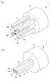
本実施形態に係る生体組織接合装置1は、図1および図2に示されるように、2対4個の電極5を備える装置本体6と、該装置本体6が接続される制御ユニット7と、該制御ユニット7に接続されたスイッチ8とを備えている。 As shown in FIGS. 1 and 2, the biological tissue bonding apparatus 1 according to the present embodiment includes a device
装置本体6は、先端に備えた電極5を、開腹部から体内に挿入するための細長いロッド9と、該ロッド9の基端側に配置され、電極5を手動により開閉するためのハンドル10とを備えている。
電極5は、ロッド9の先端に備えられたアクチュエータ11(例えば、MSC社製MHS4−16D)によって、相互に近接させる方向に連動して移動させられるようになっている。各電極5は、図2(b)に示されるように、電極5どうしが最も近接させられたときに、各対の相手の電極5との直接的な接触を防止するための絶縁材料からなる突起5aを有している。The apparatus
The
制御ユニット7は、図3に示されるように、接合に先立って電極5間に微弱電圧を加え、流れる電流を検出することにより、接合すべき生体組織の抵抗値(インピーダンス)を測定する抵抗値測定部12と、該抵抗値測定部12により測定された抵抗値に応じて、生体組織内に含有されているコラーゲンおよびエラスチンを溶融させる電圧値を算出する電圧値算出部13と、該電圧値算出部13により算出された電圧を電極5間に加える電圧印加部14と、アクチュエータ11により腸管2,3に加える圧力を発生する圧力印加部15と、これらを制御する制御部16とを備えている。 As shown in FIG. 3, the control unit 7 applies a weak voltage between the
前記スイッチ8は、例えば、フットスイッチであって、電極5によって生体組織が挟まれて接合の準備が整った状態で押下されることにより、前記制御ユニット7に備えられた制御部15にトリガ入力を付与するようになっている。制御部15は、スイッチ8からのトリガが入力されると、上述した抵抗値検出、電圧値算出、電圧の印加および圧力の印加の各作業を行わせるようになっている。 The
さらに具体的には、スイッチ8からトリガが入力され、電圧値算出部13に電圧値を算出させた制御部16は、電圧印加部14により印加する電圧と、圧力印加部15により印加する圧力とを連動して変化させるようになっている。すなわち、制御部16は、当初の圧力値を低く、時間の経過とともに徐々に高くなる圧力指令をアクチュエータ11に送るように圧力印加部15を制御するようになっている。また、制御部16は、上記圧力印加部15による圧力値の変化に同期して、当初の電圧値が高く、その後電圧値が低くなるように電圧印加部14を制御するようになっている。 More specifically, the
本実施形態においては、ハンドル10の操作によりアクチュエータ11が作動させられる場合には腸管2,3に対して過大な圧力が作用しないように、比較的低い力が発生されるように設定されている。一方、制御ユニット7によってアクチュエータ11が作動させられる場合には、それよりも大きな力を発生させることができるようになっている。 In this embodiment, when the
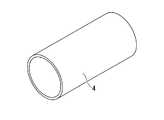
前記吻合用部材4は、図5に示されるように、筒状部材であって、ポリアニリン、ポリピロール、ポリチオフェンを複合し、あるいはカーボン粒子をドーピングしたポリ乳酸系ポリマーにより構成されている。
吻合用部材4は、ポリ乳酸系ポリマーにより構成されることによって、図6(a),(b)に示されるように、外力Fにより半径方向に潰されて、その内部開口を閉塞し内面を密着させても破断しない柔軟性を有している。また、吻合用部材4は、ポリ乳酸系ポリマーにより構成されることにより、コラーゲンの融点より高い温度に加熱されても変性しない耐熱性を有している。As shown in FIG. 5, the
As shown in FIGS. 6A and 6B, the
また、吻合用部材4は、ポリ乳酸系ポリマーにより構成されることにより、外力Fにより潰れた状態でコラーゲンの融点より高い温度に加熱された後に外力Fを解放すると、閉塞していた内部開口を開通させるように復元することができる弾性を有している。
さらに、吻合用部材4は、ポリアニリン、ポリピロール、ポリチオフェンを複合し、あるいはカーボン粒子をドーピングすることにより、導電性を有している。本実施形態においては、例えば、吻合しようとする生体組織よりも十分に低い抵抗値となるように十分に高い導電性を有している。In addition, the
Further, the
このように構成された本実施形態に係る生体組織接合装置1を用いた生体組織接合方法について、以下に説明する。
本実施形態に係る生体組織接合装置1を用いて、生体組織として、例えば、管状の生体組織である腸管2,3を吻合する場合について説明する。
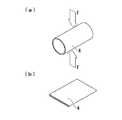
まず、図7に示されるように、吻合すべき一対の腸管2,3の接合端部2a,3aの開口に、本実施形態に係る吻合用部材4を挿入し、図8に示されるように、一対の腸管2,3の接合端部2a,3aを突き合わせた状態とする。A biological tissue joining method using the biological tissue joining apparatus 1 according to the present embodiment configured as described above will be described below.
A case will be described in which, for example, an
First, as shown in FIG. 7, the
この状態で、図8に示されるように、接合端部2a,3a近傍の半径方向外方に、本実施形態に係る生体組織接合装置1の装置本体6の先端に配置された2対の電極5を近接させる。このとき、2つの電極5対の中間位置に、一対の腸管2,3の接合端部2a,3aが配置されるようにする。そして、ハンドル10を操作することによってアクチュエータ11を作動させる。 In this state, as shown in FIG. 8, two pairs of electrodes arranged at the distal end of the
アクチュエータ11は、図2(a)および図8に矢印Aで示されるように、2対4個の電極5を相互に近接させる方向に移動させるので、図9に示されるように、その移動途中で接触した腸管2,3の外面との摩擦力によって、腸管2,3どうしをその接合端部2a,3aに向かう方向に引き寄せる。そして、図10に示されるように、吻合用部材4の内面が完全に潰れて密着するまで電極5を移動させると、腸管2,3および吻合用部材4が外力Fで半径方向に挟み込まれる。 Since the
このハンドル10の操作によるアクチュエータ11の作動により吻合用部材4に加わる外力Fによって、吻合用部材4が比較的低い圧力で挟まれる。そして、これと同時に、電極5と腸管2,3との摩擦力によって、腸管2,3どうしを、その接合端部2a,3aが相互に押し付けられる方向に付勢される。 The
吻合用部材4は、柔軟性を有しているので、図10に示されるように、外力Fによってその内部開口が閉塞され内面が密着するまで潰れることができる。この状態で、制御ユニット7に接続されているフットスイッチ8を押下することにより、図11および図12に示されるように、制御部15の作動によって、最初に抵抗値測定部12が作動させられて、電極5間に挟まれた腸管2,3の抵抗値が測定され、電圧値算出部13の作動により、印加される電圧の値が算出される。そして、制御部15は電圧印加部14を作動させて、電圧値算出部13により算出された電圧を電極5間に加える。 Since the
吻合用部材4は導電性を有しているので、電極5間には、腸管2,3および吻合用部材4を貫通して電流Iが流れ、腸管2,3の抵抗値の大きさと電流Iの大きさの2乗との積に比例した発熱量で発熱するようになる。 Since the
この場合において、本実施形態に係る吻合用部材4は、腸管2,3の抵抗値よりも十分に小さい抵抗値となるように高い導電性を有しているので、通電により吻合用部材4において発生する熱量は小さく、エネルギが無駄に浪費されることがない。また、吻合用部材4は、コラーゲンの溶融温度より高い耐熱性を有しているので、コラーゲンが溶融する温度まで加熱させられても変性せずにその性質を維持することができる。 In this case, the
そして、腸管2,3における発熱により、コラーゲンの溶融温度より若干高い温度となるように、電圧値算出部13により電極5間に加える電圧を調節しておくことにより、腸管2,3内に含有されている細胞外基質であるコラーゲンおよびエラスチンを溶融させることができる。
この状態においては、腸管2,3に含有されている溶融したコラーゲンやエラスチンが外部に染み出して流動し易くなる。Then, by adjusting the voltage applied between the
In this state, the melted collagen and elastin contained in the
本実施形態においては、このとき、電極5により腸管2,3に加えられる圧力が、比較的低く設定されているので、腸管2,3が押し潰されることなく、溶融したコラーゲンやエラスチンがその場に保持される。そして、制御部16は、電圧印加部14を制御して、発生する電圧値を十分に低下させるとともに、これに連動して、圧力印加部15を制御して、加える圧力値を増大させていく。 In the present embodiment, at this time, the pressure applied to the
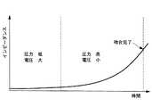
このとき、腸管2,3に加える圧力が時間的に増加すると、図4に示されるように、腸管2,3の抵抗値が時間とともに増加していく。制御部16から加える電圧値が同じであれば、腸管2,3に供給される電力量は低下していく。その結果、溶融したコラーゲンやエラスチンの温度が低下し、より粘性の高い状態へと変性する。 At this time, when the pressure applied to the
さらに、腸管2,3に加える電圧値を低下させることにより、腸管2,3に供給される電力量は低下するので、溶融したコラーゲンやエラスチンの粘性を増大させることができる。そして、電極5により加える圧力値を増大させて、4本の電極5を相互に近接する方向にさらに移動させることにより、溶融しているコラーゲンやエラスチンをしごくようにして接続端部2a,3aの方向に集めることができる。
また、4本の電極5を相互に近接する方向に移動させることにより、腸管2,3の接合端部2a,3aが離れることが防止され、より確実に接合することができる。Further, by reducing the voltage value applied to the
Further, by moving the four
その結果、接合に必要十分なコラーゲンを集めて、安定した接合力を発生させることができ、かつ、接合後の腸管2,3における柔軟性を維持することができるという利点がある。 As a result, there is an advantage that collagen necessary and sufficient for joining can be collected, a stable joining force can be generated, and flexibility in the
この状態から、電極5に加えていた電圧を停止し、図13および図14に示されるように、電極5に加えていた外力Fを解除する。吻合用部材4は弾性を有しているので、外力Fが解除されると、半径方向外方に広がるように復元し、閉塞されていた内部開口が開通する。 From this state, the voltage applied to the
すなわち、吻合用部材4の外周面においては、腸管2,3と吻合用部材4との間には、コラーゲンが浸透しているので、それが接着剤となって腸管2,3と吻合用部材4とが接着されている。一方、吻合用部材4の内面においては、接着剤となるコラーゲンは存在していないので、密着していた内面どうしは接着されず、外力Fが解除されると吻合用部材4の弾性によって離間し、開口するようになる。 That is, on the outer peripheral surface of the
これにより、図13に示されるように、電極5により挟まれていた、腸管2,3の接合端部近傍の領域Bと、その半径方向内方に配置されている吻合用部材4とが全周にわたって接着された状態で、一対の腸管2,3の接合端部2a,3aが突き合わせ状態に接合され、一体化させられる。
すなわち、本実施形態に係る生体組織接合装置1によれば、2対の電極5によって所定の外力Fにより挟みつつ電圧を加えるだけで、一対の管状の生体組織である腸管2,3を、一度に簡単に吻合することができる。As a result, as shown in FIG. 13, the region B in the vicinity of the joint end of the
That is, according to the biological tissue joining apparatus 1 according to the present embodiment, the
その結果、縫合による従来の吻合や、周方向に複数回にわたって超音波を加えることによる吻合と比較して、その作業を大幅に簡易化することができるという利点がある。特に、エネルギ治療器を取り回すための空間の少ない内視鏡的手術において、腸管2,3を半径方向に1回挟むだけのスペースを確保すれば足りるので、その吻合作業の繁雑さを大幅に低減することができるという利点がある。 As a result, there is an advantage that the operation can be greatly simplified as compared with the conventional anastomosis by suturing and the anastomosis by applying ultrasonic waves multiple times in the circumferential direction. In particular, in endoscopic surgery with little space for the energy therapy device, it is sufficient to secure a space for pinching the
また、吻合用部材4によれば、腸管2,3の内壁にコラーゲンによって接着されるので、摩擦のみによって固定していた従来の吻合用部材と比較して、その吻合状態を安定して維持することができるという利点がある。さらに、吻合用部材4によれば、生体分解性の高いポリ乳酸系ポリマーにより構成されているので、吻合手術後は、経時的に分解されて消滅するようになる。すなわち、吻合された領域Aが相互に接合して治癒する頃には、本実施形態に係る吻合用部材4が消滅することにより、体内に異物を残さなくて済むという利点もある。 Further, according to the
なお、本実施形態においては、各対の電極5を相互に近接させる加圧機構と、電極5の対どうしを近接する方向に移動させる電極移動機構と、これらを連動させる連動手段とをアクチュエータ11により一体的に構成することとし、生体組織接合装置1の先端部分の省スペースを図っているが、これらを別個に設けることにしてもよい。 In the present embodiment, the
また、本実施形態に係る生体組織接合装置1により接合する生体組織としては、腸管2,3に限定されるものではなく、他の消化管、血管あるいは尿管等の任意の管状の生体組織や皮膚等の平坦な生体組織に適用することができる。
また、本実施形態の説明においては、筒状の吻合用部材4を介在させた状態で腸管2,3を接合させることとしたが、これに代えて、吻合用部材4の形態に制限はなく、また、吻合用部材4を用いることなく接合させることとしてもよい。In addition, the biological tissue to be joined by the biological tissue joining apparatus 1 according to the present embodiment is not limited to the
In the description of the present embodiment, the
また、本実施形態においては、腸管2,3に加える圧力を増大させるのと同時に加える電圧値を低下させることとしたが、これに代えて、電圧値については一定に維持することにしてもよい。
また、本実施形態においては、生体組織に供給するエネルギとして電極5により電気エネルギを供給することとしたが、これに代えて、超音波振動子を接触させることにより超音波振動を供給することにしてもよい。Further, in the present embodiment, the voltage value applied at the same time as increasing the pressure applied to the
In the present embodiment, the electrical energy is supplied from the
1 生体組織接合装置
2,3 腸管(生体組織)
5 電極
11 アクチュエータ(加圧機構、電極移動機構、連動手段)
14 電力供給部
16 制御部1 Biological
5
14
Claims (7)
Translated fromJapanese各対の電極間に電力を供給する電力供給部と、
接合されるべき生体組織を挟んだ位置に配置された各対の電極を相互に近接させる方向に移動させる加圧機構と、
電極対どうしを相互に近接させる方向に移動させる電極移動機構と、
前記電力供給部、前記加圧機構および前記電極移動機構を制御する制御部とを備え、
該制御部が、生体組織を2対の電極によって所定の圧力で挟んだ状態で前記電力供給部により電極間に電力を供給し、その後、前記加圧機構により2対の電極が生体組織を挟む圧力を増加させて、前記電極移動機構により電極対どうしを相互に近接させる方向に移動させるよう制御する生体組織接合装置。Two pairs of electrodes;
A power supply for supplying power between each pair of electrodes;
A pressurizing mechanism for moving each pair of electrodes arranged at positions sandwiching the biological tissues to be joined in a direction to approach each other;
An electrode moving mechanism for moving electrode pairs in a direction to bring them close to each other;
A controller that controls the power supply unit, the pressurizing mechanism, and the electrode moving mechanism;
The control unit supplies power between the electrodes by the power supply unit in a state where the biological tissue is sandwiched between the two pairs of electrodes at a predetermined pressure, and then the two pairs of electrodes sandwich the biological tissue by the pressurizing mechanism. A biological tissue joining apparatus that controls to increase the pressure and move the electrode pairs in a direction to bring them close to each other by the electrode moving mechanism.
その後、生体組織を第1の圧力よりも高い第2の圧力で挟んだ状態で、電極対どうしを相互に近接させる方向に移動させる生体組織接合方法。Supplying power between the electrodes in a state where the living tissue to be joined by the two pairs of electrodes is sandwiched between the first pressures,
Thereafter, the living tissue joining method of moving the electrode pairs in a direction to bring them close to each other in a state where the living tissue is sandwiched between the second pressure higher than the first pressure.
Priority Applications (1)
| Application Number | Priority Date | Filing Date | Title |
|---|---|---|---|
| JP2007333010AJP2009153620A (en) | 2007-12-25 | 2007-12-25 | Instrument and method for joining biological tissue |
Applications Claiming Priority (1)
| Application Number | Priority Date | Filing Date | Title |
|---|---|---|---|
| JP2007333010AJP2009153620A (en) | 2007-12-25 | 2007-12-25 | Instrument and method for joining biological tissue |
Publications (1)
| Publication Number | Publication Date |
|---|---|
| JP2009153620Atrue JP2009153620A (en) | 2009-07-16 |
Family
ID=40958292
Family Applications (1)
| Application Number | Title | Priority Date | Filing Date |
|---|---|---|---|
| JP2007333010APendingJP2009153620A (en) | 2007-12-25 | 2007-12-25 | Instrument and method for joining biological tissue |
Country Status (1)
| Country | Link |
|---|---|
| JP (1) | JP2009153620A (en) |
Cited By (1)
| Publication number | Priority date | Publication date | Assignee | Title |
|---|---|---|---|---|
| WO2015025745A1 (en) | 2013-08-21 | 2015-02-26 | オリンパスメディカルシステムズ株式会社 | Treatment tool and treatment system |
Citations (5)
| Publication number | Priority date | Publication date | Assignee | Title |
|---|---|---|---|---|
| JPS50126083U (en)* | 1974-04-01 | 1975-10-16 | ||
| JPH10510460A (en)* | 1995-09-19 | 1998-10-13 | ヴァリーラブ・インコーポレーテッド | Energy supply system for vessel sealing |
| JP2002502660A (en)* | 1998-02-12 | 2002-01-29 | コンソーシアム マネージメント サービスィズ グループ インコーポレイテッド | Soft tissue joining method by passing high-frequency current inside |
| JP2005515016A (en)* | 2002-01-25 | 2005-05-26 | エルベ エレクトロメディツィン ゲーエムベーハー | Device for forming an anastomosis between hollow organs |
| JP2009125442A (en)* | 2007-11-27 | 2009-06-11 | Olympus Corp | Biotissue joining device |
- 2007
- 2007-12-25JPJP2007333010Apatent/JP2009153620A/enactivePending
Patent Citations (5)
| Publication number | Priority date | Publication date | Assignee | Title |
|---|---|---|---|---|
| JPS50126083U (en)* | 1974-04-01 | 1975-10-16 | ||
| JPH10510460A (en)* | 1995-09-19 | 1998-10-13 | ヴァリーラブ・インコーポレーテッド | Energy supply system for vessel sealing |
| JP2002502660A (en)* | 1998-02-12 | 2002-01-29 | コンソーシアム マネージメント サービスィズ グループ インコーポレイテッド | Soft tissue joining method by passing high-frequency current inside |
| JP2005515016A (en)* | 2002-01-25 | 2005-05-26 | エルベ エレクトロメディツィン ゲーエムベーハー | Device for forming an anastomosis between hollow organs |
| JP2009125442A (en)* | 2007-11-27 | 2009-06-11 | Olympus Corp | Biotissue joining device |
Cited By (1)
| Publication number | Priority date | Publication date | Assignee | Title |
|---|---|---|---|---|
| WO2015025745A1 (en) | 2013-08-21 | 2015-02-26 | オリンパスメディカルシステムズ株式会社 | Treatment tool and treatment system |
Similar Documents
| Publication | Publication Date | Title |
|---|---|---|
| JP6940537B2 (en) | Equipment and methods for sealing tissues with low power | |
| CA2321247C (en) | Bonding of soft biological tissues by passing high frequency electric current therethrough | |
| CN102292045B (en) | Treatment device and treatment tool for treatment | |
| EP2197380B1 (en) | Electrosurgical instrument and method | |
| JP5123437B2 (en) | THERAPEUTIC TREATMENT TOOL, THERAPEUTIC TREATMENT DEVICE, AND THERAPEUTIC TREATMENT METHOD | |
| JP5231658B2 (en) | THERAPEUTIC TREATMENT DEVICE AND METHOD OF CONTROLLING THE TREATMENT TREATMENT DEVICE | |
| JP5123435B2 (en) | THERAPEUTIC TREATMENT TOOL, THERAPEUTIC TREATMENT DEVICE, AND THERAPEUTIC TREATMENT METHOD | |
| US20090024126A1 (en) | Tissue fusion device | |
| WO2006104836A3 (en) | Apparatus for regulating tissue welder jaws | |
| US9050088B2 (en) | Anastomosis ring and anastomosis ring arrangement | |
| JP2016511096A (en) | Surgical instrument with multiple clamping mechanisms | |
| AU2011302615A1 (en) | Electrosurgical tissue sealing augmented with a seal-enhancing composition | |
| JP5389996B2 (en) | THERAPEUTIC TREATMENT TOOL, THERAPEUTIC TREATMENT DEVICE, AND THERAPEUTIC TREATMENT METHOD | |
| KR20200088329A (en) | Electrically weldable suture material, apparatus and method for forming welded suture loops and other welded structures | |
| US9750562B2 (en) | Treatment instrument | |
| JP2008301955A (en) | Biomedical tissue joining apparatus | |
| JP2009153620A (en) | Instrument and method for joining biological tissue | |
| JP2009125442A (en) | Biotissue joining device | |
| US9370344B2 (en) | Method of fusing layers of biological tissue | |
| JP5127307B2 (en) | Anastomosis | |
| JP2010057688A (en) | High frequency therapeutic apparatus | |
| JP5519244B2 (en) | Biological tissue treatment device | |
| JP2010057686A (en) | Living body tissue bonding device | |
| JP2011101744A (en) | Living tissue treatment apparatus | |
| JP6203459B1 (en) | Energy device |
Legal Events
| Date | Code | Title | Description |
|---|---|---|---|
| A621 | Written request for application examination | Free format text:JAPANESE INTERMEDIATE CODE: A621 Effective date:20101027 | |
| A977 | Report on retrieval | Free format text:JAPANESE INTERMEDIATE CODE: A971007 Effective date:20120830 | |
| A131 | Notification of reasons for refusal | Free format text:JAPANESE INTERMEDIATE CODE: A131 Effective date:20120904 | |
| A02 | Decision of refusal | Free format text:JAPANESE INTERMEDIATE CODE: A02 Effective date:20130108 |