JP2009149249A - Image display device and image display program, and driving assist system using image display device - Google Patents
Image display device and image display program, and driving assist system using image display deviceDownload PDFInfo
- Publication number
- JP2009149249A JP2009149249AJP2007330650AJP2007330650AJP2009149249AJP 2009149249 AJP2009149249 AJP 2009149249AJP 2007330650 AJP2007330650 AJP 2007330650AJP 2007330650 AJP2007330650 AJP 2007330650AJP 2009149249 AJP2009149249 AJP 2009149249A
- Authority
- JP
- Japan
- Prior art keywords
- vehicle
- image information
- image
- host vehicle
- image display
- Prior art date
- Legal status (The legal status is an assumption and is not a legal conclusion. Google has not performed a legal analysis and makes no representation as to the accuracy of the status listed.)
- Pending
Links
Images


Landscapes
- Fittings On The Vehicle Exterior For Carrying Loads, And Devices For Holding Or Mounting Articles (AREA)
Abstract
Description
Translated fromJapanese本発明は、自車両が後退する際に自車両周辺の画像を表示する画像表示装置及び画像表示プログラム、並びに画像表示装置を用いた運転支援装置に関する。 The present invention relates to an image display device and an image display program for displaying an image around the host vehicle when the host vehicle moves backward, and a driving support device using the image display device.
近年、移動体としての車両を走行させる運転者が、特に確認しにくい車両の後方をバックカメラを用いて容易に確認できる構成が知られている。この構成は、バックカメラを車両の後方の状況が撮像可能に配設するとともに、撮像した画像データを車内に配設した表示手段に表示させる。例えば、以下の特許文献1に記載されたナビゲーション装置では、バックカメラにより車両の後方を撮像しておき、移動方向認識手段により車両が後退していることが認識された場合に、撮像された車両後方の画像データを表示部に表示させる制御を行うことが記載されている。 2. Description of the Related Art In recent years, a configuration is known in which a driver traveling a vehicle as a moving body can easily check the rear of a vehicle that is particularly difficult to check using a back camera. In this configuration, the rear camera is disposed so that the situation behind the vehicle can be imaged, and the captured image data is displayed on the display means disposed in the vehicle. For example, in the navigation device described in Patent Document 1 below, the vehicle is imaged when the rear of the vehicle is imaged by the back camera and the movement direction recognition means recognizes that the vehicle is moving backward. It is described that control for displaying rear image data on a display unit is performed.
安全確認を容易とするため車両の後退時に車両後方の画像データを取得して表示手段に表示させることは勿論有用である。しかし、従来から行われているバックカメラによる撮像では、表示部に表示される画像は車両後方の限られた範囲のみであった。そのため、例えば、道路に面した駐車場に前向きに駐車をした後、後退しながら出庫して道路に合流する場合や、道路を走行中に切り返しを行う際に後退しながら道路に合流する場合等には、車両後方の画像データを表示するだけでは、当該道路上を通常の走行速度で走行している車両や車両の側方から接近してくる歩行者等を適切に確認することができないため、結局、運転者は合流しようとする道路の他の車両の走行状況や歩行者の通行状況等を目視で確認しながらゆっくりと後退する必要があった。 In order to facilitate safety confirmation, it is of course useful to acquire the image data behind the vehicle and display it on the display means when the vehicle moves backward. However, in conventional imaging with a back camera, the image displayed on the display unit is only a limited range behind the vehicle. Therefore, for example, after parking forward in a parking lot facing the road, when leaving the car and rejoining the road, or when joining the road while retreating when turning on the road, etc. Therefore, simply displaying the image data behind the vehicle cannot adequately confirm a vehicle traveling on the road at a normal traveling speed or a pedestrian approaching from the side of the vehicle. Eventually, the driver needed to slowly retreat while visually confirming the traveling conditions of other vehicles on the road to be merged and the traffic conditions of pedestrians.
また、合流しようとする道路の他の車両の走行状況や歩行者の通行状況等を目視で確認するにしても、その確認できる範囲はやはり限られており、いずれにしても、車両を後退させながら道路に合流する際は注意を払うべき項目が非常に多く、運転者には多大な労力がかかっていた。 In addition, even if the traveling conditions of other vehicles on the road to be joined and the traffic conditions of pedestrians are visually confirmed, the range that can be confirmed is still limited. However, there were a lot of items to pay attention to when joining the road, and the driver took a lot of labor.
本発明は、上記課題に鑑みてなされたものであり、車両を後退させながら道路に合流する場合に、ユーザに適切に安全を確認させることのできる画像表示装置及び画像表示プログラム、並びに画像表示装置を用いた運転支援装置を提供すること目的とする。 The present invention has been made in view of the above-described problems, and an image display device, an image display program, and an image display device that allow a user to appropriately confirm safety when joining a road while reversing a vehicle. It is an object of the present invention to provide a driving support device using a vehicle.
この目的を達成するための本発明に係る、自車両が後退する際に自車両周辺の画像を表示する画像表示装置の特徴構成は、自車両の後方の画像情報である後方画像情報、自車両の後部右方の画像情報である右方画像情報、及び、自車両の後部左方の画像情報である左方画像情報、をそれぞれ独立に取得する画像情報取得手段と、自車両が後退しながら車両の走行エリアに合流しようとしているか否かを判定する合流判定手段と、前記合流判定手段による判定結果に基づいて、前記後方画像情報のみを表示する状態と、前記右方画像情報及び前記左方画像情報の少なくとも一方を表示する状態と、を切り替える画像表示手段と、を備える点にある。 In order to achieve this object, according to the present invention, a characteristic configuration of an image display device that displays an image around the host vehicle when the host vehicle is moving backward includes rear image information that is image information behind the host vehicle, and the host vehicle. Image information acquisition means for independently acquiring right-side image information, which is image information on the rear right side, and left-side image information, which is image information on the rear left side of the host vehicle, while the host vehicle is moving backward Junction determining means for determining whether or not to join the traveling area of the vehicle, a state in which only the rear image information is displayed based on a determination result by the merge determining means, the right image information and the left An image display means for switching between a state in which at least one of the image information is displayed and an image display means for switching the image information.
上記の特徴構成によれば、画像情報取得手段が後方画像情報、右方画像情報及び左方画像情報をそれぞれ独立に取得するとともに、合流判定手段により、自車両が後退しながら車両の走行エリアに合流しようとしているか否かを判定する。ここで、本明細書において走行エリアとは、車両や人等の移動体が移動するためのエリアを意味し、一般の道路や駐車場内通行路等の車両の通行エリア、更には歩行者が歩行するための歩行エリアをも含む概念である。そして、合流判定手段による判定結果に基づいて、画像表示手段に表示される画像情報が、後方画像情報のみを含むものと、右方画像情報及び左方画像情報の少なくとも一方を含むものと、の間で切り替えられる。よって、車両の後方だけでなく後部左右方向の画像情報をも画像表示手段に表示することができる。また、自車両が後退しながら車両の走行エリアに合流しようとしているか単に後退しようとしているだけかに応じて、画像表示手段に表示する画像情報を適切に切り替えることができる。したがって、ユーザに適切に安全を確認させることが可能となる。 According to the above characteristic configuration, the image information acquisition unit acquires the rear image information, the right side image information, and the left side image information independently, and the merge determination unit sets the vehicle information in the traveling area of the vehicle while moving backward. Judge whether or not to join. Here, in this specification, the traveling area means an area for moving a moving body such as a vehicle or a person, and a traffic area of a vehicle such as a general road or a traffic path in a parking lot, and further a pedestrian walks. It is a concept that includes a walking area to do. Then, based on the determination result by the merging determination unit, the image information displayed on the image display unit includes only the rear image information and the one including at least one of the right image information and the left image information. Can be switched between. Therefore, not only the rear of the vehicle but also the image information in the rear left and right direction can be displayed on the image display means. In addition, the image information displayed on the image display means can be appropriately switched depending on whether the host vehicle is going to join the traveling area of the vehicle while moving backward or simply going backward. Therefore, it is possible to make the user confirm safety appropriately.
ここで、前記画像表示手段は、前記合流判定手段が自車両が後退しながら車両の走行エリアに合流しようとしていると判定した場合には、前記右方画像情報及び前記左方画像情報を表示し、前記合流判定手段が自車両が後退しながら車両の走行エリアに合流しようとしていないと判定した場合には、前記後方画像情報を表示すると好適である。 Here, the image display means displays the right image information and the left image information when the merge determining means determines that the own vehicle is going to merge into the traveling area of the vehicle while moving backward. When the joining determination means determines that the host vehicle is not going to join the traveling area of the vehicle while moving backward, it is preferable to display the rear image information.
自車両が後退しながら車両の走行エリアに合流する場合には、走行エリアを走行する他の車両や走行エリアに沿って歩行する歩行者の有無を確認する必要性が高い。一方、自車両が後退するものの車両の走行エリアに合流するわけではない場合、例えば、自車両を駐車場に駐車する場合等には、自車両の後方に存在する障害物の有無を確認する必要性が高い。よって、この構成によれば、画像表示手段は、合流判定手段が自車両が後退しながら車両の走行エリアに合流しようとしていると判定した場合には右方画像情報及び左方画像情報を表示し、合流判定手段が自車両が後退しながら車両の走行エリアに合流しようとしていないと判定した場合には後方画像情報を表示する。よって、車両の後退時の状況に合わせてそれぞれ確認すべき方向に応じた画像情報を画像表示手段に表示して、ユーザに適切に安全を確認させることが可能となる。 When the host vehicle retreats and merges with the traveling area of the vehicle, there is a high need to confirm the presence of other vehicles traveling in the traveling area and the presence of pedestrians walking along the traveling area. On the other hand, when the host vehicle moves backward but does not merge with the traveling area of the vehicle, for example, when the host vehicle is parked in a parking lot, it is necessary to check whether there is an obstacle behind the host vehicle. High nature. Therefore, according to this configuration, the image display means displays the right image information and the left image information when the merging determination means determines that the host vehicle is going backward and is about to merge with the traveling area of the vehicle. When the joining determination means determines that the host vehicle is not moving and is not going to join the traveling area of the vehicle, the rear image information is displayed. Therefore, it is possible to display the image information corresponding to the direction to be confirmed according to the situation when the vehicle is moving backward on the image display means, and to allow the user to appropriately confirm the safety.
また、自車両の現在位置を表す自車位置情報を取得する自車位置情報取得手段と、前記自車位置情報に基づいて、自車位置周辺の地図情報を取得する地図情報取得手段と、を備え、前記合流判定手段は、自車両が後退していると判定された場合であって、かつ、自車位置周辺の道路リンクに対して自車位置が近づく方向に移動している場合に、自車両が後退しながら車両の走行エリアに合流しようとしていると判定すると好適である。 In addition, own vehicle position information acquisition means for acquiring own vehicle position information representing the current position of the own vehicle, and map information acquisition means for acquiring map information around the own vehicle position based on the own vehicle position information, The merging determination means is a case where it is determined that the host vehicle is moving backward, and when the host vehicle position is moving in a direction approaching a road link around the host vehicle position, It is preferable to determine that the host vehicle is going to join the traveling area of the vehicle while moving backward.
自車両が合流しようとしている車両の走行エリアが一般の道路である場合には、当該道路に対応する道路リンクの情報が地図情報に含まれている。この構成によれば、自車両が後退していると判定された場合において、この道路リンクの情報と自車位置情報とを利用して、自車両が後退しながら車両の走行エリアに合流しようとしているか否かを判定することができ、上記したような効果を得ることができる。 When the traveling area of the vehicle that the host vehicle is about to join is a general road, the map information includes road link information corresponding to the road. According to this configuration, when it is determined that the host vehicle is moving backward, the road vehicle information and the vehicle position information are used to join the vehicle traveling area while the host vehicle is moving backward. It is possible to determine whether or not there is an effect as described above.
また、自車両が走行中の運転状況を検知する運転状況検知手段を備え、前記合流判定手段は、前記運転状況検知手段により検知される自車両の運転状況に基づいて、自車両が切り返して後退を始める前の状況であると判定した場合に、自車両が後退しながら車両の走行エリアに合流しようとしていると判定すると好適である。 In addition, the vehicle is provided with a driving condition detection unit that detects a driving condition while the host vehicle is traveling, and the merging determination unit is configured to switch back based on the driving condition of the host vehicle detected by the driving condition detection unit. When it is determined that the situation is before starting the vehicle, it is preferable to determine that the host vehicle is going to join the traveling area of the vehicle while moving backward.
車両が道路を走行中に切り返しを行う場合にも、後退しながら車両の走行エリアに合流する場面が生じる。このとき、切り返して後退を始める前の運転状況には一定のパターンがあり、このパターンと自車両の実際の運転状況とを照合することで切り返して後退しようとしていることを判定することができる。よって、この構成によれば、運転状況検知手段により検知される自車両の運転状況に基づいて、自車両が後退しながら車両の走行エリアに合流しようとしているか否かを判定することができ、上記したような効果を得ることができる。 Even when the vehicle turns over while traveling on the road, there is a scene where the vehicle joins the traveling area of the vehicle while moving backward. At this time, there is a certain pattern in the driving situation before turning back and starting to reverse, and it can be determined that the vehicle is turning back and going backward by comparing this pattern with the actual driving situation of the host vehicle. Therefore, according to this configuration, it is possible to determine whether or not the own vehicle is going to join the traveling area of the vehicle while retreating based on the driving situation of the own vehicle detected by the driving situation detecting unit. The effect which was done can be acquired.
また、車両のエンジンが始動してからの経過時間を表す始動経過時間を計測する経過時間計測手段を備え、前記合流判定手段は、前記合流判定手段は、前記経過時間取得手段により取得された始動経過時間が予め設定された所定時間に達する前に自車両が後退していると判定された場合に、自車両が後退しながら車両の走行エリアに合流しようとしていると判定すると好適である。 The apparatus further comprises elapsed time measuring means for measuring an elapsed elapsed time representing an elapsed time since the start of the vehicle engine, wherein the merge determining means is the start acquired by the elapsed time acquiring means. If it is determined that the host vehicle is moving backward before the elapsed time reaches a predetermined time, it is preferable to determine that the host vehicle is going to join the traveling area of the vehicle while moving backward.
車両に乗って移動する際に、エンジンをかけてすぐに後退する場合には、駐車スペースから後退して出る場合と考えられるので、後退しながら車両の走行エリアに合流する場面が生じ得る。よって、この構成によれば、少なくともエンジンの始動後一定の時間が経過するまでの間には、自車両が後退を開始するまでの時間に基づいて、自車両が後退しながら車両の走行エリアに合流しようとしているか否かを判定することができ、上記したような効果を得ることができる。 When moving on a vehicle, if the engine is turned back immediately after starting the engine, it is considered that the vehicle moves backward from the parking space, so that there may be a scene where the vehicle merges into the traveling area of the vehicle while moving backward. Therefore, according to this configuration, at least until a certain time has elapsed after the engine is started, based on the time until the host vehicle starts to move backward, the host vehicle moves back into the traveling area of the vehicle. It can be determined whether or not to join, and the above-described effects can be obtained.
本発明に係る運転支援装置の特徴構成は、上記の各構成を備えた画像表示装置と、道路上を移動する車両又は人を対象障害物とし、前記後方画像情報、前記右方画像情報及び前記左方画像情報に含まれる前記対象障害物の画像認識処理を行う障害物認識手段と、前記障害物認識手段により前記対象障害物の画像認識に成功した場合に警告を発する警告手段と、を備える点にある。 The characteristic configuration of the driving support device according to the present invention is an image display device having each of the above configurations, a vehicle or a person moving on a road as a target obstacle, the rear image information, the right image information, and the Obstacle recognition means for performing image recognition processing of the target obstacle included in the left image information; and warning means for issuing a warning when the obstacle recognition means has succeeded in image recognition of the target obstacle. In the point.
この特徴構成によれば、画像表示装置は、自車両が後退しながら車両の走行エリアに合流しようとしているか否かに応じて、それぞれ適した画像情報を画像表示手段に表示するとともに、警告手段は、取得された画像情報に含まれる道路上を移動する車両又は人を画像認識した場合に警告を発する。よって、ユーザに適切に安全を確認させることが可能となるとともに、安全運転を支援することが可能となる。 According to this characteristic configuration, the image display device displays suitable image information on the image display unit according to whether or not the host vehicle is going to join the traveling area of the vehicle while moving backward, and the warning unit is When a vehicle or a person moving on the road included in the acquired image information is recognized as an image, a warning is issued. Therefore, it is possible to allow the user to appropriately confirm safety and to support safe driving.
また、本発明に係る自車両が後退する際に自車両周辺の画像を表示する画像表示プログラムの特徴構成は、自車両の後方の画像情報である後方画像情報、自車両の後部右方の画像情報である右方画像情報、及び、自車両の後部左方の画像情報である左方画像情報、をそれぞれ独立に取得する画像情報取得ステップと、自車両が後退しながら車両の走行エリアに合流しようとしているか否かを判定する合流判定ステップと、前記合流判定ステップによる判定結果に基づいて、前記後方画像情報のみを表示する状態と、前記右方画像情報及び前記左方画像情報の少なくとも一方を表示する状態と、を切り替える画像表示ステップと、をコンピュータに実行させる点にある。 In addition, the characteristic configuration of the image display program for displaying an image around the host vehicle when the host vehicle according to the present invention moves backward includes rear image information that is image information behind the host vehicle, and an image on the rear right side of the host vehicle. Image information acquisition step for independently acquiring right image information that is information and left image information that is image information on the rear left side of the host vehicle, and the host vehicle joins the vehicle travel area while moving backward Based on a determination result obtained by the merge determination step for determining whether or not to perform the determination, the state in which only the rear image information is displayed, and at least one of the right image information and the left image information are displayed. The image display step for switching between the display state and the display state is performed by the computer.
この特徴構成によれば、画像情報取得ステップにより後方画像情報、右方画像情報及び左方画像情報をそれぞれ独立に取得するとともに、合流判定ステップにより、自車両が後退しながら車両の走行エリアに合流しようとしているか否かを判定する。そしてその判定結果に基づいて、画像表示ステップにおいて、画像情報が、後方画像情報のみを含むものと右方画像情報及び左方画像情報の少なくとも一方を含むものとの間で切り替えられて表示される。よって、車両の後方だけでなく後部左右方向の画像情報をも画像表示手段に表示することができる。また、画像表示手段に表示する画像情報を、自車両が後退しながら車両の走行エリアに合流しようとしているか単に後退しようとしているだけかに応じて、それぞれ適した画像情報を表示することができる。したがって、ユーザに適切に安全を確認させることが可能となる。 According to this feature configuration, the rear image information, the right image information, and the left image information are independently acquired by the image information acquisition step, and the own vehicle is rejoined to the traveling area of the vehicle while retreating by the merge determination step. Determine if you are going to do it. Based on the determination result, in the image display step, the image information is switched and displayed between the information including only the rear image information and the information including at least one of the right image information and the left image information. . Therefore, not only the rear of the vehicle but also the image information in the rear left and right direction can be displayed on the image display means. Also, the image information displayed on the image display means can be displayed as appropriate image information depending on whether the host vehicle is going to join the traveling area of the vehicle while moving backward or simply going backward. Therefore, it is possible to make the user confirm safety appropriately.
〔第一の実施形態〕
次に、本発明の第一の実施形態について図面を参照して説明する。
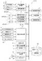
図1は、本実施形態に係る画像表示装置3を備える運転支援装置2を含むナビゲーション装置1の概略構成を示すブロック図である。ナビゲーション装置1は、自車位置表示、目的地までの進路案内等の通常のナビゲーション機能を発揮する。画像表示装置3は、自車両が後退する際に自車両周辺の画像を表示するものであって、後方画像情報GB、右方画像情報GR及び左方画像情報GLをそれぞれ独立に取得する。また、画像表示装置3は、自車両が後退しながら車両の走行エリア41(図4参照)に合流しようとしているか否かを判定し、その判定結果に基づいて画像表示手段に表示する画像情報Gを、後方画像情報GBのみを含むものと右方画像情報GR及び左方画像情報GLの少なくとも一方を含むものとの間で切り替える。これにより、車両を後退させながら道路に合流する場合に、適切に安全を確認することが可能となる。また、画像情報Gに含まれる車両又は人等の障害物を画像認識した場合に、警告を発してユーザに対して注意喚起を行う。これにより、安全運転を支援することが可能となる。[First embodiment]
Next, a first embodiment of the present invention will be described with reference to the drawings.
FIG. 1 is a block diagram illustrating a schematic configuration of a navigation device 1 including a driving support device 2 including an image display device 3 according to the present embodiment. The navigation device 1 exhibits normal navigation functions such as displaying the position of the vehicle and guiding the route to the destination. The image display device 3 displays an image around the host vehicle when the host vehicle moves backward, and independently acquires the rear image information GB, the right image information GR, and the left image information GL. Further, the image display device 3 determines whether or not the host vehicle is going to join the traveling area 41 (see FIG. 4) of the vehicle while moving backward, and the image information G displayed on the image display means based on the determination result. Are switched between those including only the rear image information GB and those including at least one of the right image information GR and the left image information GL. This makes it possible to appropriately check safety when joining the road while the vehicle is moving backward. Further, when an obstacle such as a vehicle or a person included in the image information G is recognized as an image, a warning is issued to alert the user. This makes it possible to support safe driving.
図1に示すナビゲーション装置1の各機能部、具体的には、自車位置情報取得部4、地図情報取得部5、画像情報取得部6、後退判定部7、合流判定部8、ナビゲーション用演算部12及び障害物認識部13は、CPU等の演算処理装置を中核部材として、入力されたデータに対して種々の処理を行うための機能部がハードウェア又はソフトウェア(プログラム)或いはその両方により実装されて構成されている。そして、これらの各機能部は、互いに情報の受け渡しを行うことができるように構成されている。また、ナビゲーション装置1は、これらの各機能部からの出力に基づいて必要な画像を表示する画像表示部9を備え、地図データベースDBは、例えば、ハードディスクドライブ、DVD−ROMを備えたDVDドライブ、CD−ROMを備えたCDドライブ等のように、情報を記憶可能な記録媒体とその駆動手段とを有する装置をハードウェア構成として備えている。以下、本実施形態に係るナビゲーション装置1の各部の構成について詳細に説明する。 Each function part of the navigation apparatus 1 shown in FIG. 1, specifically, the own vehicle position information acquisition part 4, the map
1.地図データベース
地図データベースDBは、所定の区画毎に分けられた地図情報Mが記憶されたデータベースである。図2は、地図データベースDBに記憶されている地図情報Mの構成の例を示す図である。この図に示すように、地図情報Mは、交差点に対応する多数のノードnと、各交差点間を結ぶ道路に対応するリンクkとの接続関係により道路ネットワークを表す道路情報を有している。各ノードnは、緯度及び経度で表現された地図上の位置(座標)の情報を有している。各リンクkは、ノードnを介して接続されており、その属性情報として、道路種別、地域種別、リンク長、道路幅、リンク形状を表現するための形状補間点等の情報を有している。1. Map database The map database DB is a database in which map information M divided into predetermined sections is stored. FIG. 2 is a diagram illustrating an example of the configuration of the map information M stored in the map database DB. As shown in this figure, the map information M has road information representing a road network by connection relations between a large number of nodes n corresponding to intersections and links k corresponding to roads connecting the intersections. Each node n has information on the position (coordinates) on the map expressed by latitude and longitude. Each link k is connected via the node n, and has attribute information such as road type, area type, link length, road width, and shape interpolation point for expressing the link shape. .
2.自車位置情報取得部
自車位置情報取得部4は、自車両の現在位置を示す自車位置情報Pを取得する自車位置情報取得手段として機能する。ここでは、自車位置情報取得部4は、GPS受信機21、方位センサ22、及び距離センサ23と接続されている。ここで、GPS受信機21は、GPS(Global Positioning System)衛星からのGPS信号を受信する装置である。このGPS信号は、通常1秒おきに受信され、自車位置情報取得部4へ出力される。自車位置情報取得部4では、GPS受信機21で受信されたGPS衛星からの信号を解析し、自車両の現在位置(緯度及び経度)、進行方位、移動速度等の情報を取得することができる。方位センサ22は、自車両の進行方位又はその進行方位の変化を検出するセンサである。この方位センサ22は、例えば、ジャイロセンサ、地磁気センサ、ハンドルの回転部に取り付けた光学的な回転センサや回転型の抵抗ボリューム、車輪部に取り付ける角度センサ等により構成される。そして、方位センサ22は、その検出結果を自車位置情報取得部4へ出力する。距離センサ23は、自車両の車速や移動距離を検出するセンサである。この距離センサ23は、例えば、車両のドライブシャフトやホイール等が一定量回転する毎にパルス信号を出力する車速パルスセンサ、自車両の加速度を検知するヨー・Gセンサ及び検知された加速度を積分する回路等により構成される。そして、距離センサ23は、その検出結果としての車速及び移動距離の情報を自車位置情報取得部4へ出力する。2. Own vehicle position information acquisition unit The own vehicle position information acquisition unit 4 functions as own vehicle position information acquisition means for acquiring own vehicle position information P indicating the current position of the own vehicle. Here, the vehicle position information acquisition unit 4 is connected to the
そして、自車位置情報取得部4は、これらのGPS受信機21、方位センサ22及び距離センサ23からの出力に基づいて、公知の方法により自車位置を特定する演算を行い、緯度及び経度で表された自車両の現在位置の情報、及び自車両の進行方位の情報を含む自車位置情報Pを取得する。 And the own vehicle position information acquisition part 4 performs the calculation which pinpoints an own vehicle position by a well-known method based on the output from these
3.地図情報取得部
地図情報取得部5は、後退判定部7による後退判定の処理に用いるために、自車位置情報Pに基づいて、自車位置周辺の地図情報Mを地図データベースDBから取得する地図情報取得手段として機能する。地図情報取得部5により抽出された地図情報Mは、後退判定部7へ出力される。また、地図情報取得部5は、ナビゲーション用演算部12によるナビゲーション処理に用いるために、ナビゲーション用演算部12から要求があった領域の地図情報Mを地図データベースDBから抽出し、ナビゲーション用演算部12へ出力する。3. Map information acquisition unit The map
4.画像情報取得部
画像情報取得部6は、自車両の後方の画像情報である後方画像情報GB、自車両の後部右方の画像情報である右方画像情報GR、及び、自車両の後部左方の画像情報である左方画像情報GL、を取得する画像情報取得手段として機能する。ここで、後方画像情報GB、右方画像情報GR及び左方画像情報GLは、それぞれ後方撮像装置24B、右方撮像装置24R及び左方撮像装置24Lを用いて独立に取得される。なお、本明細書における以下の説明において「画像情報G」とは、特に明記しない限り、後方画像情報GB、右方画像情報GR及び左方画像情報GLのうち、不特定のいずれか一つ以上を意味するものとし、同様に「撮像装置24」とは、特に明記しない限り、後方撮像装置24B、右方撮像装置24R及び左方撮像装置24Lのうち、不特定のいずれか一つ以上を意味するものとする。4). Image information acquisition unit The image
撮像装置24は、撮像素子を備えた車載カメラ等である。後方撮像装置24Bは、少なくとも自車両の後方周辺を撮像可能な位置に設けられる。このような後方撮像装置24Bとしては、例えば図3に示すような、自車両の後方を撮像するバックカメラを用いると好適である。また、右方撮像装置24R及び左方撮像装置24Lは、少なくとも自車両の後部右方及び後部左方を撮像可能な位置に設けられる。右方撮像装置24R及び左方撮像装置24Lは、後方撮像装置24Bに比べて比較的遠方までの領域を撮像可能となっている。このような右方撮像装置24R及び左方撮像装置24Lとしては、例えば図3に示すような、自車両の後部右方及び後部左方を撮像するバックサイドカメラを用いると好適である。
なお、右方撮像装置24R及び左方撮像装置24Lは、それぞれ自車両の後部において幅方向に沿って外側向きに配置され、各撮像装置24の軸方向を基準とする一定角度内の領域を撮像可能となっている。図3(b)にはその一例として軸方向を基準とする±45度内の領域を撮像可能に構成してある例を示した。また、後方撮像装置24Bは、自車両の後方周辺の比較的自車両に近い領域を幅広く撮像可能である。これらの撮像装置24により、自車両の後方及び後部左右方向の全領域がほぼ死角なく撮像される。The
Note that the
画像情報取得部6は、撮像装置24により撮像したアナログの撮像情報を所定の時間間隔で取り込み、デジタル信号の画像情報Gに変換して取得する。この際の画像情報Gの取り込みの時間間隔は、例えば、10〜50ms程度とすることができる。これにより、画像情報取得部6は、撮像装置24により撮像した複数フレームの画像情報Gを連続的に取得することができる。ここで取得された画像情報Gは、画像表示部9及び障害物認識部13へ出力される。 The image
5.後退判定部
後退判定部7は、自車両が後退しているか否かを判定する後退判定手段として機能する。本実施形態において、後退判定部7は、車両のシフトレバーの位置を示すシフト位置に基づいて自車両が後退しているか否かを判定する。具体的には、車両の変速機のシフトレバーにシフト位置検出センサ31が内蔵されており、このシフト位置検出センサ31が、シフト位置が「P(パーキング)」、「N(ニュートラル)」、「R(リバース)」、「D(ドライブ)」、「2(セカンド)」、「L(ロー)」のいずれの位置となっているかを検出する。そして、シフト位置が「R(リバース)」の位置となっていることを検出した場合に、後退判定部7はその検出結果を受け取って自車両が後退していると判定する。一方、シフト位置が「R(リバース)」以外の位置となっている場合には、自車両は後退していないと判定する。後退判定部7による判定結果は合流判定部8及び障害物認識部13へ出力される。5. Reverse determination unit The
6.合流判定部
合流判定部8は、自車両が後退していると判定された場合であって、かつ、自車両が後退しながら車両の走行エリア41に合流しようとしているか否かを判定する合流判定手段として機能する。本実施形態においては、合流判定部8による合流判定は、後退判定部7から自車両が後退しているとの判定結果を受け取った場合に行われる。また、本実施形態において合流判定部8は、自車位置情報取得部4により取得される自車位置情報P及び地図情報取得部5により取得される自車位置周辺の地図情報Mに基づき、リンクkに対して自車位置が近づく方向に移動している場合に、自車両が後退しながら車両の走行エリア41に合流しようとしていると判定する。一方、リンクkに対して自車位置が離れる方向に移動している場合や、リンクkに対して自車位置が近づきも離れもしていない場合には、自車両が後退しながら車両の走行エリア41に合流しようとしていないと判定する。6). Join determination unit The
図4は、本実施形態における合流判定を説明するための説明図である。この図においては、自車両が後退しながら車両の走行エリア41に合流する可能性がある場合の一例として、駐車場内の駐車スペース42が道路に直接面している場合について説明する。例えば、道路沿いに位置する住宅や賃貸マンション等の駐車スペース42が道路に直接面している場合が考えられる。このような場合には、駐車スペース42に自車両を駐車する際に前向きに入庫する場合も多く、出庫の際には後退しながら道路に合流しなければならないことになる。図4(a)には出庫の際の自車両の走行軌跡を実際の道路状況に応じて示し、更に図4(b)には、自車位置情報取得部4により取得される自車位置情報P及び地図情報取得部5により取得される地図情報Mに基づき、リンクkと自車位置との位置関係を図4(a)に対応させて示した。なお、図4(b)において○と△の組み合わせで示されている自車位置マーク43が自車位置を示している。この図から分かるように、自車両が駐車スペース42から道路に合流する際には、当該道路に対応するリンクkに対して自車位置マーク43が近づく方向に移動する。そのため、この場合において合流判定部8は、自車両が後退しながら車両の走行エリア41に合流しようとしていると判定し、その結果を表示画像選択部10へ出力する。 FIG. 4 is an explanatory diagram for explaining the merge determination in the present embodiment. In this figure, the case where the
一方、上記の例において、後退しながら入庫して後ろ向きに駐車する場合について考えてみる。この場合、図示はしないが、自車両が道路から駐車スペース42に入庫する際には、当該道路に対応するリンクkから自車位置マーク43が離れる方向に移動することになる。そのため、この場合において合流判定部8は、自車両が後退しながら車両の走行エリア41に合流しようとしていないと判定し、その結果を表示画像選択部10へ出力する。 On the other hand, in the above example, let us consider a case where the user enters the vehicle while retreating and parks backward. In this case, although not shown, when the host vehicle enters the
7.画像表示部
画像表示部9は、合流判定部8による判定結果に基づいて、後方画像情報GBのみを表示する状態と、右方画像情報GR及び左方画像情報GLの少なくとも一方を表示する状態と、を切り替える画像表示手段として機能する。画像表示部9は、合流判定部8による判定結果に基づいて、画像表示部9に表示する画像情報Gを選択する表示画像選択部10と、表示画像選択部10により選択された画像情報Gを表示する表示部11と、を備える。本明細書においては、特に区別して使用しない限り、画像表示部9とは、表示画像選択部10と表示部11とを合わせたものを意味するものとする。7). Image display unit The image display unit 9 displays only the rear image information GB based on the determination result by the
7−1.表示画像選択部
表示画像選択部10は、合流判定部8による判定結果に基づいて、画像表示部9に表示する画像情報Gを、後方画像情報GBのみを含むものと、右方画像情報GR及び左方画像情報GLの少なくとも一方を含むものと、から選択する表示画像選択手段として機能する。本実施形態においては、表示画像選択部10は、合流判定部8が、自車両が後退しながら車両の走行エリア41に合流しようとしていないと判定した場合には、後方画像情報GBのみを選択する。一方、合流判定部8が、自車両が後退しながら車両の走行エリア41に合流しようとしていると判定した場合には、右方画像情報GR及び左方画像情報GLの二つを選択する。表示画像選択部10により選択された画像情報Gは、表示部11へ出力される。7-1. Display Image Selection Unit The display
7−2.表示部
表示部11は、表示画像選択部10により選択された画像情報Gを表示する表示手段として機能する。本実施形態においては、表示部11は、表示画像選択部10からの出力を受け取り、合流判定部8が、自車両が後退しながら車両の走行エリア41に合流しようとしていないと判定した場合、例えば、駐車場内で単に後退しながら駐車スペース42に入庫しようとしている場合等には、図5(a)に示すように後方画像情報GBを単独表示する。一方、合流判定部8が、自車両が後退しながら車両の走行エリア41に合流しようとしていると判定した場合、例えば、図4を参照して説明したような場合等には、図5(b)に示すように右方画像情報GR及び左方画像情報GLを並べて表示する。なお、図5においては、表示部11を幅方向に二分割し、右側に右方画像情報GRを、左側に左方画像情報GLを配置して、二つの画像情報Gを左右に並べて表示している。7-2. Display Unit The
なお、本実施形態においては、画像表示部9は液晶表示装置等の表示装置とタッチパネル等の入力装置とが一体として構成されている。 In the present embodiment, the image display unit 9 is configured by integrating a display device such as a liquid crystal display device and an input device such as a touch panel.
8.ナビゲーション用演算部
ナビゲーション用演算部12は、自車位置表示、出発地から目的地までの進路案内、目的地検索等のナビゲーション機能を実行するためにアプリケーションプログラムAPに従って動作する演算処理手段である。例えば、ナビゲーション用演算部12は、地図情報取得部5を介して自車位置情報Pに基づいて地図データベースDBから自車両周辺の地図情報Mを取得し、画像表示部9に地図の画像を表示するとともに、当該地図の画像上に自車位置情報Pに基づいて自車位置マーク43を重ね合わせて表示する処理を行う。また、ナビゲーション用演算部12は、ユーザから目的地の設定を受け付け、設定された目的地と地図データベースDBに記憶された地図情報Mとに基づいて、自車位置から目的地までの経路探索を行う。また、ナビゲーション用演算部12は、画像表示部9及びスピーカ等を有して構成された音声出力装置25に接続されており、探索された出発地から目的地までの経路と自車位置情報Pとに基づいて、画像表示部9及び音声出力装置25の一方又は双方を用いて、ユーザに対する経路案内を行う。8). Navigation Calculation Unit The
なお、ナビゲーション用演算部12は、障害物認識部13からの出力を受け、その出力内容に応じた運転支援案内を画像表示部9及び音声出力装置25の一方又は双方に対して出力する。具体的には、障害物認識部13からの出力が「対象障害物の画像が抽出できた」ものである場合には、ナビゲーション用演算部12は「車両又は人が近づいているので注意すべき」旨の案内を出力し、一方、障害物認識部13からの出力が「対象障害物の画像が抽出できなかった」ものである場合には、ナビゲーション用演算部12は「注意しながらであれば後退しても良い」旨の案内を出力する。したがって、本実施形態においては、ナビゲーション用演算部12と音声出力装置25とが一体となって、障害物認識部13により対象障害物Oの画像認識に成功した場合に警告を発する警告手段として機能している。 The
9.障害物認識部
障害物認識部13は、道路上を移動する車両又は人を対象障害物Oとし、後方画像情報GB、右方画像情報GR及び左方画像情報GLに含まれる対象障害物Oの画像認識処理を行う障害物認識手段として機能する。本実施形態において障害物認識部13は、後退判定部7から、自車両が後退している旨の出力を受けたとき、画像情報取得部6で取得された画像情報Gに含まれる障害物(車両、人又は道路上の固定物等)の画像認識処理を開始する。判定地物の画像認識に際しては、画像情報Gに対して二値化処理やエッジ検出処理等を行い、当該画像情報Gに含まれている障害物の輪郭情報を抽出する。障害物認識部13は、抽出した障害物の輪郭情報と対象障害物Oである車両又は人の形態の特徴量とのパターンマッチングを行うことにより、画像情報Gに含まれる対象障害物Oの画像を抽出する。車両又は人の形態の特徴量は、予め記憶されている。障害物認識部13は、取得された画像情報Gに対して対象障害物Oの画像認識処理を行い、対処障害物の画像を抽出できたか否かについての結果を、ナビゲーション用演算部12に出力する。9. Obstacle recognizing unit The
10.運転支援処理の手順
次に、本実施形態に係るナビゲーション装置1に含まれる、画像表示装置3を備えた運転支援装置2において実行される運転支援処理の手順について説明する。図6は、本実施形態に係る画像表示処理を含む運転支援処理の手順を示すフローチャートである。以下に説明する運転支援処理の手順は、上記の運転支援装置2の各機能部を構成するハードウェア又はソフトウェア(プログラム)或いはその両方の組み合せにより実行される。運転支援装置2の各機能部がプログラムにより構成される場合には、運転支援装置2が有する演算処理装置は、上記の各機能部を構成する画像表示プログラム及びこれを含む運転支援プログラムを実行するコンピュータとして動作する。10. Next, the procedure of the driving support process executed in the driving support device 2 including the image display device 3 included in the navigation device 1 according to the present embodiment will be described. FIG. 6 is a flowchart illustrating a procedure of driving support processing including image display processing according to the present embodiment. The procedure of the driving support process described below is executed by hardware or software (program) constituting each functional unit of the driving support device 2 or a combination of both. When each functional unit of the driving support device 2 is configured by a program, the arithmetic processing device included in the driving support device 2 executes the image display program configuring each of the above functional units and the driving support program including the image display program. Operates as a computer.
まず、自車位置情報取得部4は、自車位置情報Pを取得する(ステップ#01)。次に地図情報取得部5は、自車位置情報Pに基づいて自車位置周辺の地図情報Mを取得する(ステップ#02)。このとき地図情報Mに含まれるリンクkの情報が取得される。次にシフト位置検出センサ31は、シフトレバーが後退を示す位置にあるか否かを判定する(ステップ#03)。シフトレバーが後退を示す位置にあると判定されたとき(ステップ#03:Yes)、後退判定部7は自車両が後退していると判定して、画像情報Gを取得する(ステップ#04)。一方、シフトレバーが後退を示す位置にあると判定されなかった場合には(ステップ#03:No)処理は終了する。次に合流判定部8は、自車位置情報P及び自車位置周辺の地図情報Mに基づき、リンクkに対して自車位置が近づく方向に移動しているか否かを判定する(ステップ#05)。リンクkに対して自車位置が近づく方向に移動していると判定されたとき(ステップ#05:Yes)、画像表示部9は右方画像情報GR及び左方画像情報GLを並べて表示する(ステップ#06)。一方、リンクkに対して自車位置が近づく方向に移動していないと判定されたとき(ステップ#05:No)、画像表示部9は後方画像情報GBを表示する(ステップ#07)。
このような画像表示処理によれば、自車両が後退しながら車両の走行エリア41に合流しようとしているか否かに応じて、それぞれ適した画像情報Gを表示することができる。すなわち、自車両が後退しながら車両の走行エリア41に合流しようとしている場合には、接近中の車両や歩行者がいないかどうかを確認するべく走行エリア41に沿った左右方向の画像情報Gを表示し、自車両が後退しながら車両の走行エリア41に合流しようとしているわけではない場合には、自車両の後方に他の車両や固定物等がないかどうかを確認するべく比較的自車両に近く幅広い領域の後方画像情報GBを表示することができる。したがって、ユーザに適切に安全を確認させることが可能となる。First, the vehicle position information acquisition unit 4 acquires the vehicle position information P (step # 01). Next, the map
According to such image display processing, it is possible to display suitable image information G depending on whether or not the host vehicle is going to join the traveling
次に、障害物認識部13は、道路上を移動する車両又は人を対象障害物Oとして、画像情報Gに含まれる対象障害物Oの画像認識処理を行う(ステップ#08)。障害物認識部13は、画像情報Gに含まれている障害物から抽出した輪郭情報と対象障害物Oである車両又は人の形態の特徴量とのパターンマッチングを行うことにより、画像情報Gに対象障害物Oの画像が含まれるか否かを判断する(ステップ#09)。画像情報Gに対象障害物Oの画像が含まれると判定された場合には(ステップ#09:Yes)、ナビゲーション用演算部12は、画像表示部9及び音声出力装置25の一方又は双方を介してユーザに対して注意喚起等の警告を行う(ステップ#10)。一方、画像情報Gに対象障害物Oの画像が含まれないと判定された場合には(ステップ#09:No)、ナビゲーション用演算部12は、ユーザに対して注意しながら後退するように案内する(ステップ#11)。次にシフト位置検出センサ31は、シフトレバーが後退を示す位置にあるか否かを判定する(ステップ#12)。シフトレバーが後退を示す位置にあると判定されたとき(ステップ#12:Yes)、再度ステップ#05〜#11の処理を繰り返す。一方、シフトレバーが後退以外を示す位置にあると判定された場合には(ステップ#12:No)処理は終了する。
このような運転支援処理によれば、取得された画像情報Gに含まれる道路上を移動する車両又は人の画像認識に成功した場合には警告を発し、それ以外の場合には注意しながら後退するように案内する。よって、ユーザの安全運転を支援することが可能となる。Next, the
According to such a driving support process, a warning is issued when image recognition of a vehicle or a person moving on a road included in the acquired image information G is successful, and the vehicle retreats with caution in other cases. Guide you to do. Therefore, it is possible to support the user's safe driving.
〔第二の実施形態〕
次に、本発明の第二の実施形態について説明する。
図7は、本実施形態に係る画像表示装置3を備える運転支援装置2を含むナビゲーション装置1の概略構成を示すブロック図である。基本的には第一の実施形態の場合とほぼ同様であるが、運転状況検知部14を備える点、合流判定部8が合流判定を行うための判断基準及び画像表示部9に表示される画像情報Gが第一の実施形態と相違している。以下では、本実施形態に係るナビゲーション装置1について、第一の実施形態との相違点を中心に説明する。[Second Embodiment]
Next, a second embodiment of the present invention will be described.
FIG. 7 is a block diagram illustrating a schematic configuration of the navigation device 1 including the driving support device 2 including the image display device 3 according to the present embodiment. Basically, it is almost the same as in the case of the first embodiment, except that the driving
11.運転状況検知部
運転状況検知部14は、自車両が走行中の運転状況を検知する運転状況検知手段として機能する。運転状況検知部14には、車速センサ32、操舵角センサ33、シフト位置検出センサ31、アクセルセンサ34、ブレーキセンサ35などのセンサが接続されている。車速センサ32は、車両の車輪に取り付けられたアクティブ車輪速センサからなり、車輪の回転速度を検出して速度信号として出力する。操舵角センサ33は、ステアリング装置の内部に取り付けられており、ステアリングホイールを転舵した場合の舵角を検出して操舵角信号として出力する。シフト位置検出センサ31は、シフトレバーに内蔵され、シフト位置が「P(パーキング)」、「N(ニュートラル)」、「R(リバース)」、「D(ドライブ)」、「2(セカンド)」、「L(ロー)」のいずれの位置となっているかを検出する。アクセルセンサ34は運転者のアクセル操作量を検出し、ブレーキセンサ35は運転者のブレーキ操作量を検出する。運転状況検知部14は、これらのセンサ群からの信号入力に基づいて、車両の運転状況、例えば、通常走行状況や後進走行状況、その他にも切り返しを行う前の切返前走行状況等も判定することができる。運転状況検知部14により検知された車両の運転状況は、合流判定部8及び表示画像選択部10へ出力される。11. Driving situation detection unit The driving
なお、運転状況検知部14は、車速センサ32からのセンサ出力に基づいて、自車両が後退しているか否かを判定することもできる。具体的には、車速センサ32から出力される電気信号に対応する車輪の回転速度が負の値をとる場合に自車両が後退していると判定し、一方、車輪の回転速度が正の値をとる場合には、自車両は後退していないと判定する。したがって、運転状況検知部14は、自車両が後退しているか否かを判定する後退判定手段としても機能し、自車両の運転状況の検知と同時に後退判定を行うことが可能となっている。 The driving
12.合流判定部
合流判定部8は、自車両が後退しながら車両の走行エリア41に合流しようとしているか否かを判定する合流判定手段として機能する。本実施形態においては、合流判定部8は、運転状況検知部14により検知される自車両の運転状況に基づいて、自車両が切り返して後退を始める前の状況であると判定した場合に、自車両が後退しながら車両の走行エリア41に合流しようとしていると判定する。一方、自車両が切り返して後退を始める前の状況ではないと判定された場合には、自車両が後退しながら車両の走行エリア41に合流しようとしていないと判定する。このように、本実施形態においては、後退判定と合流判定とが同時に実行される。12 Junction Determining Unit The
図8は、本実施形態における合流判定を説明するための説明図である。図8では、自車両が後退しながら車両の走行エリア41に合流する可能性がある場合の一例として、車両が道路を走行中に切り返しを行う場合について説明する。この図には切り返しを行う際の自車両の走行軌跡を実際の道路状況に応じて示している。このときの、ユーザによる車両の操作状況としては、まず状態(A)ではシフト位置を「D(ドライブ)」としてアクセルを踏み、通常の走行をしている。その後、ユーザが切り返しを行う場合、切返地点に向けて減速するため状態(A)から状態(B)までの間、アクセルを放して徐々にブレーキを踏み込む。状態(B)の時点では十分に減速されており、ここから状態(C)までの間、ステアリング装置を操作して道路脇の空きスペースへ向けて車両の進行方向を変更するとともに、更にブレーキを踏み込んで状態(C)において完全に停止させる。その後、シフトレバーのシフト位置を「D(ドライブ)」から「R(リバース)」に切り替える。ここから状態(D)にかけて、ステアリング装置を適切に操作して車両が所望の方向を向くように操作して停止する。最後に、シフトレバーのシフト位置を「R(リバース)」から「D(ドライブ)」に切り替え、アクセルを踏み込んで発進する。運転状況検知部14は、このユーザの操作状況に対応した車両の運転状況を検知する。 FIG. 8 is an explanatory diagram for explaining the merge determination in the present embodiment. In FIG. 8, as an example of a case where the host vehicle may join the traveling
合流判定部8は、運転状況検知部14により検知された車両の運転状況に基づいて、自車両が切り返して後退を始める前の状況であるか否かを判定する。なお、上記の説明における、状態(C)においてシフトレバーのシフト位置を「D(ドライブ)」から「R(リバース)」に切り替えるまでの一連の動作に対応した運転状況が、ここでいう切返前走行状況となる。合流判定部8は、運転状況検知部14により検知される自車両の運転状況が、切返前走行状況であると判定した場合には自車両が後退しながら車両の走行エリア41に合流しようとしていると判定し、その結果を表示画像選択部10へ出力する。 Based on the driving situation of the vehicle detected by the driving
13.画像表示部
画像表示部9は、合流判定部8による判定結果に基づいて、後方画像情報GBのみを表示する状態と、右方画像情報GR及び左方画像情報GLの少なくとも一方を表示する状態と、を切り替える画像表示手段として機能する。画像表示部9は、合流判定部8による判定結果に基づいて、画像表示部9に表示する画像情報Gを選択する表示画像選択部10と、表示画像選択部10により選択された画像情報Gを表示する表示部11と、を備える。13. Image display unit The image display unit 9 displays only the rear image information GB based on the determination result by the
13−1.表示画像選択部
表示画像選択部10は、合流判定部8による判定結果に基づいて、画像表示部9に表示する画像情報Gを、後方画像情報GBのみを含むものと、右方画像情報GR及び左方画像情報GLの少なくとも一方を含むものと、から選択する表示画像選択手段として機能する。本実施形態においては、表示画像選択部10は、合流判定部8が、自車両が後退しながら車両の走行エリア41に合流しようとしていないと判定した場合には、後方画像情報GBのみを選択する。一方、合流判定部8が、自車両が後退しながら車両の走行エリア41に合流しようとしていると判定した場合には、右方画像情報GR、左方画像情報GL、後方画像情報GBの三つ全てを選択する。表示画像選択部10により選択された画像情報Gは、表示部11へ出力される。13-1. Display Image Selection Unit The display
13−2.表示部
表示部11は、表示画像選択部10により選択された画像情報Gを表示する表示手段として機能する。本実施形態においては、表示部11は、表示画像選択部10からの出力を受け取り、合流判定部8が、自車両が後退しながら車両の走行エリア41に合流しようとしていないと判定した場合には、図9(a)に示すように後方画像情報GBを単独表示する。一方、合流判定部8が、自車両が後退しながら車両の走行エリア41に合流しようとしていると判定した場合には、図9(b)に示すように後方画像情報GB、右方画像情報GR、左方画像情報GLの全てを表示する。このようにすれば、常にユーザに車両の後方の安全を確認させることを可能としつつ、状況に応じて車両の後部左右方向の安全を確認させることも可能となる。
なお、図9(b)の例では、表示部11をまず上下に二分割して下側に後方画像情報GBを表示し、上側を更に左右に二分割して右側に右方画像情報GRを、左側に左方画像情報GLを表示している。しかし、これらの画像情報Gの配置についてはこの限りではなく、例えば、表示部11を幅方向を三等分して三つの画像情報Gを順に並べて表示しても良い。その場合、配列の順序についても任意の順序とすることができる。13-2. Display Unit The
In the example of FIG. 9B, the
14.運転支援処理の手順
次に、本実施形態に係るナビゲーション装置1に含まれる、画像表示装置3を備えた運転支援装置2において実行される運転支援処理の手順について説明する。図10は、本実施形態に係る画像表示処理を含む運転支援処理の手順を示すフローチャートである。以下に説明する運転支援処理の手順は、上記の運転支援装置2の各機能部を構成するハードウェア又はソフトウェア(プログラム)或いはその両方の組み合せにより実行される。運転支援装置2の各機能部がプログラムにより構成される場合には、運転支援装置2が有する演算処理装置は、上記の各機能部を構成する画像表示プログラム及びこれを含む運転支援プログラムを実行するコンピュータとして動作する。14 Next, the procedure of the driving support process executed in the driving support device 2 including the image display device 3 included in the navigation device 1 according to the present embodiment will be described. FIG. 10 is a flowchart illustrating a procedure of driving support processing including image display processing according to the present embodiment. The procedure of the driving support process described below is executed by hardware or software (program) constituting each functional unit of the driving support device 2 or a combination of both. When each functional unit of the driving support device 2 is configured by a program, the arithmetic processing device included in the driving support device 2 executes the image display program configuring each of the above functional units and the driving support program including the image display program. Operates as a computer.
まず、運転状況検知部14は、車両の運転状況を検知する(ステップ#21)。画像情報取得部6は画像情報Gを取得する(ステップ#22)。次に、合流判定部8は、運転状況検知部14により検知される自車両の運転状況が、切返前走行状況であるか否かを判定する(ステップ#23)。切返前走行状況であると判定された場合には(ステップ#23:Yes)、画像表示部9は後方画像情報GB、右方画像情報GR、左方画像情報GLの全てを表示する(ステップ#24)。一方、切返前走行状況ではないと判定された場合には(ステップ#23:No)、次に運転状況検知部14は、自車両が後退しているか否かを判定する(ステップ#25)。自車両が後退していると判定された場合には(ステップ#25:Yes)、画像表示部9は後方画像情報GBを表示する(ステップ#26)。一方、自車両が後退していないと判定された場合には(ステップ#25:No)、処理は終了する。 First, the driving
次に、障害物認識部13は、道路上を移動する車両又は人を対象障害物Oとして、画像情報Gに含まれる対象障害物Oの画像認識処理を行う(ステップ#27)。障害物認識部13は、画像情報Gに含まれている障害物から抽出した輪郭情報と対象障害物Oである車両又は人の形態の特徴量とのパターンマッチングを行うことにより、画像情報Gに対象障害物Oの画像が含まれるか否かを判断する(ステップ#28)。画像情報Gに対象障害物Oの画像が含まれると判定された場合には(ステップ#28:Yes)、ナビゲーション用演算部12は、画像表示部9及び音声出力装置25の一方又は双方を介してユーザに対して注意喚起等の警告を行う(ステップ#29)。一方、画像情報Gに対象障害物Oの画像が含まれないと判定された場合には(ステップ#28:No)、ナビゲーション用演算部12は、ユーザに対して注意しながら後退するように案内する(ステップ#30)。次に運転状況検知部14は、車速センサ32からの出力に基づいて自車両が後退しているか否かを判定する(ステップ#31)。自車両が後退していると判定された場合には(ステップ#31:Yes)、再度ステップ#23〜#30の処理を繰り返す。一方、自車両が後退していないと判定された場合には(ステップ#31:No)処理は終了する。 Next, the
〔第三の実施形態〕
次に、本発明の第三の実施形態について説明する。
本実施形態に係るナビゲーション装置1の概略構成は、基本的には第一の実施形態の場合とほぼ同様であるが、図1において一点破線で示している経過時間計測部15を備えている点及び合流判定部8が合流判定を行うための判断基準が第一の実施形態と相違している。以下では、本実施形態に係るナビゲーション装置1について、第一の実施形態との相違点を中心に説明する。[Third embodiment]
Next, a third embodiment of the present invention will be described.
The schematic configuration of the navigation device 1 according to the present embodiment is basically the same as that of the first embodiment, but includes an elapsed
15.経過時間計測部
経過時間計測部15は、車両のエンジンが始動してからの経過時間を表す始動経過時間を計測する経過時間計測手段として機能する。経過時間計測部15は、車両のイグニッションスイッチがONとなった時点を基準として経過時間の計測を始める。経過時間計測部15により計測された始動経過時間は、合流判定部8へ出力される。15. Elapsed Time Measurement Unit The elapsed
16.合流判定部
合流判定部8は、自車両が後退しながら車両の走行エリア41に合流しようとしているか否かを判定する合流判定手段として機能する。本実施形態においては、合流判定部8は、経過時間計測部15により計測された始動経過時間が予め設定された所定時間に達する前に、後退判定部7により自車両が後退していると判定された場合に、自車両が後退しながら車両の走行エリア41に合流しようとしていると判定する。一方、経過時間計測部15により計測された始動経過時間が予め設定された所定時間に達する前に、後退判定部7により自車両が後退していると判定されなかった場合には、自車両が後退しながら車両の走行エリア41に合流しようとしていないと判定する。このような合流判定は、駐車していた車両に乗って移動する際に、エンジンをかけてすぐに後退する場合には、駐車スペース42から後退して出る場合と考えられるので、道路、あるいは駐車場内の車両の通行エリアに合流する場合があるという事象に基づくものである。16. Junction Determining Unit The
17.運転支援処理の手順
次に、本実施形態に係るナビゲーション装置1に含まれる、画像表示装置3を備えた運転支援装置2において実行される運転支援処理の手順について説明する。図11は、本実施形態に係る画像表示処理を含む運転支援処理の手順を示すフローチャートである。以下に説明する運転支援処理の手順は、上記の運転支援装置2の各機能部を構成するハードウェア又はソフトウェア(プログラム)或いはその両方の組み合せにより実行される。運転支援装置2の各機能部がプログラムにより構成される場合には、運転支援装置2が有する演算処理装置は、上記の各機能部を構成する画像表示プログラム及びこれを含む運転支援プログラムを実行するコンピュータとして動作する。17. Next, the procedure of the driving support process executed in the driving support device 2 including the image display device 3 included in the navigation device 1 according to the present embodiment will be described. FIG. 11 is a flowchart showing a procedure of driving support processing including image display processing according to the present embodiment. The procedure of the driving support process described below is executed by hardware or software (program) constituting each functional unit of the driving support device 2 or a combination of both. When each functional unit of the driving support device 2 is configured by a program, the arithmetic processing device included in the driving support device 2 executes the image display program configuring each of the above functional units and the driving support program including the image display program. Operates as a computer.
まず、ユーザによるイグニッションスイッチのON操作を受け付け(ステップ#41)、エンジンの始動と同時に、経過時間計測部15は始動経過時間の計測を開始する(ステップ#42)。次にシフト位置検出センサ31は、シフトレバーが後退を示す位置にあるか否かを判定する(ステップ#43)。シフトレバーが後退を示す位置にあると判定されたとき(ステップ#43:Yes)、後退判定部7は自車両が後退していると判定して、画像情報Gを取得する(ステップ#44)。一方、シフトレバーが後退を示す位置にあると判定されなかった場合には(ステップ#43:No)処理は終了する。次に合流判定部8は、始動経過時間が所定時間を経過する前にシフトレバーが後退を示す位置に変更されたか否かを判定する(ステップ#45)。始動経過時間が所定時間を経過する前にシフトレバーが後退を示す位置に変更されたと判定された場合(ステップ#45:Yes)、画像表示部9は右方画像情報GR及び左方画像情報GLを並べて表示する(ステップ#46)。一方、始動経過時間が所定時間を経過する前にシフトレバーが後退を示す位置に変更されたと判定された場合には(ステップ#45:No)、画像表示部9は後方画像情報GBを表示する(ステップ#47)。 First, an ON operation of the ignition switch by the user is accepted (step # 41), and the elapsed
次に、障害物認識部13は、道路上を移動する車両又は人を対象障害物Oとして、画像情報Gに含まれる対象障害物Oの画像認識処理を行う(ステップ#48)。障害物認識部13は、画像情報Gに含まれている障害物から抽出した輪郭情報と対象障害物Oである車両又は人の形態の特徴量とのパターンマッチングを行うことにより、画像情報Gに対象障害物Oの画像が含まれるか否かを判断する(ステップ#49)。画像情報Gに対象障害物Oの画像が含まれると判定された場合には(ステップ#49:Yes)、ナビゲーション用演算部12は、画像表示部9及び音声出力装置25の一方又は双方を介してユーザに対して注意喚起等の警告を行う(ステップ#50)。一方、画像情報Gに対象障害物Oの画像が含まれないと判定された場合には(ステップ#49:No)、ナビゲーション用演算部12は、ユーザに対して注意しながら後退するように案内する(ステップ#51)。次にシフト位置検出センサ31は、シフトレバーが後退を示す位置にあるか否かを判定する(ステップ#52)。シフトレバーが後退を示す位置にあると判定されたとき(ステップ#52:Yes)、再度ステップ#45〜#51の処理を繰り返す。一方、シフトレバーが後退以外を示す位置にあると判定された場合には(ステップ#52:No)処理は終了する。 Next, the
〔その他の実施形態〕
(1)上記の各実施形態においては、合流判定部8が自車両が後退しながら車両の走行エリア41に合流しようとしていると判定するための判定条件をそれぞれ具体的に説明したが、これら以外の条件に基づいて合流判定を行うように構成されていても良い。例えば、シフト位置が「R(リバース)」の位置にあって、かつ、後方撮像装置24Bからの後方画像情報GBに含まれる、路側帯との境界を示す白線等の道路標示の画像認識に成功した場合に、合流判定部8は自車両が後退しながら車両の走行エリア41に合流しようとしていると判定しても良い。[Other Embodiments]
(1) In each of the above-described embodiments, the determination conditions for determining that the merging
(2)上記の各実施形態においては、合流判定部8はそれぞれ異なる判定条件に基づいて合流判定を行う例について説明した。しかし、これらの判定条件を複数個備えた構成として、その中の任意の数の条件を満たした場合、例えば、いずれか一つの条件を満たした場合や、全ての条件を満たした場合に、合流判定部8は自車両が後退しながら車両の走行エリア41に合流しようとしていると判定するようにしても良い。(2) In each of the embodiments described above, the example in which the merging
(3)上記の第一及び第三の実施形態においては、合流判定部8が自車両が後退しながら車両の走行エリア41に合流しようとしていると判定した場合には、画像表示部9に右方画像情報GR及び左方画像情報GLを表示する例を示し、上記の第二の実施形態においては、合流判定部8が自車両が後退しながら車両の走行エリア41に合流しようとしていると判定した場合には、画像表示部9には後方画像情報GB、右方画像情報GR、左方画像情報GLの全てを表示する例を示した。しかし、合流判定部8が自車両が車両の走行エリア41に合流しようとしていると判定した場合に画像表示部9に表示する画像情報Gには、右方画像情報GR及び左方画像情報GLの少なくとも一方が含まれていれば良く、例えば、後退時の進行方向に応じて右方画像情報GR又は左方画像情報GLをそれぞれ単独で表示したり、後方画像情報GB及び右方画像情報GRを並べて表示したり、あるいは、後方画像情報GB及び左方画像情報GLを並べて表示したりしても良い。(3) In the first and third embodiments described above, when the joining
本発明は、自車両が後退する際に自車両周辺の画像を表示する画像表示装置及び画像表示プログラム、並びに画像表示装置を用いた運転支援装置に好適に利用することができる。 INDUSTRIAL APPLICABILITY The present invention can be suitably used for an image display device and an image display program that display an image around the host vehicle when the host vehicle moves backward, and a driving support device using the image display device.
2 運転支援装置
3 画像表示装置
4 自車位置情報取得部
5 地図情報取得部
6 画像情報取得部
8 合流判定部
9 画像表示部
13 障害物認識部
14 運転状況検知部
15 経過時間計測部
25 音声出力装置(警告手段)
M 地図情報
P 自車位置情報
k リンク
GB 後方画像情報
GR 右方画像情報
GL 左方画像情報
O 対象障害物2 Driving support device 3 Image display device 4 Own vehicle position
M Map information P Own vehicle position information k Link GB Rear image information GR Right image information GL Left image information O Target obstacle
Claims (7)
Translated fromJapanese自車両の後方の画像情報である後方画像情報、自車両の後部右方の画像情報である右方画像情報、及び、自車両の後部左方の画像情報である左方画像情報、をそれぞれ独立に取得する画像情報取得手段と、
自車両が後退しながら車両の走行エリアに合流しようとしているか否かを判定する合流判定手段と、
前記合流判定手段による判定結果に基づいて、前記後方画像情報のみを表示する状態と、前記右方画像情報及び前記左方画像情報の少なくとも一方を表示する状態と、を切り替える画像表示手段と、
を備える画像表示装置。An image display device that displays an image of the vicinity of the host vehicle when the host vehicle moves backward,
Rear image information, which is image information behind the host vehicle, right image information, which is image information on the right rear of the host vehicle, and left image information, which is image information on the left rear of the host vehicle, are independent of each other. Image information acquisition means for acquiring,
Merging determination means for determining whether or not the own vehicle is going to merge with the traveling area of the vehicle while reversing;
Image display means for switching between a state in which only the rear image information is displayed and a state in which at least one of the right image information and the left image information is displayed based on a determination result by the merge determination means;
An image display device comprising:
前記合流判定手段が自車両が後退しながら車両の走行エリアに合流しようとしていると判定した場合には、前記右方画像情報及び前記左方画像情報を表示し、
前記合流判定手段が自車両が後退しながら車両の走行エリアに合流しようとしていないと判定した場合には、前記後方画像情報を表示する請求項1に記載の画像表示装置。The image display means includes
When it is determined that the joining determination means is about to join the traveling area of the vehicle while the host vehicle is moving backward, the right image information and the left image information are displayed,
The image display device according to claim 1, wherein the rear image information is displayed when the joining determination unit determines that the host vehicle is not moving and is not going to join the traveling area of the vehicle.
前記自車位置情報に基づいて、自車位置周辺の地図情報を取得する地図情報取得手段と、を備え、
前記合流判定手段は、自車両が後退していると判定された場合であって、かつ、自車位置周辺の道路リンクに対して自車位置が近づく方向に移動している場合に、自車両が後退しながら車両の走行エリアに合流しようとしていると判定する請求項1又は2に記載の画像表示装置。Own vehicle position information acquisition means for acquiring own vehicle position information representing the current position of the own vehicle;
Map information acquisition means for acquiring map information around the vehicle position based on the vehicle position information,
The joining determination means is a case where it is determined that the host vehicle is moving backward, and the host vehicle is moving in a direction in which the host vehicle position approaches the road link around the host vehicle position. The image display device according to claim 1, wherein the image display device determines that the vehicle is going to join the traveling area of the vehicle while retreating.
前記合流判定手段は、前記運転状況検知手段により検知される自車両の運転状況に基づいて、自車両が切り返して後退を始める前の状況であると判定した場合に、自車両が後退しながら車両の走行エリアに合流しようとしていると判定する請求項1から3のいずれか一項に記載の画像表示装置。Provided with driving status detection means for detecting the driving status while the vehicle is traveling,
The merging determination means determines that the situation is a situation before the own vehicle turns back and starts to reverse based on the driving situation of the own vehicle detected by the driving situation detection means. The image display device according to claim 1, wherein the image display device determines that the vehicle is about to join the traveling area.
前記合流判定手段は、前記経過時間取得手段により取得された始動経過時間が予め設定された所定時間に達する前に自車両が後退していると判定された場合に、自車両が後退しながら車両の走行エリアに合流しようとしていると判定する請求項1から4のいずれか一項に記載の画像表示装置。Elapsed time measuring means for measuring the elapsed elapsed time representing the elapsed time since the start of the vehicle engine,
The merging determination means determines that the own vehicle is moving backward when it is determined that the own vehicle is moving backward before the elapsed start time acquired by the elapsed time acquiring means reaches a predetermined time set in advance. 5. The image display device according to claim 1, wherein the image display device determines that the vehicle is about to join the traveling area.
道路上を移動する車両又は人を対象障害物とし、前記後方画像情報、前記右方画像情報及び前記左方画像情報に含まれる前記対象障害物の画像認識処理を行う障害物認識手段と、
前記障害物認識手段により前記対象障害物の画像認識に成功した場合に警告を発する警告手段と、
を備える運転支援装置。An image display device according to any one of claims 1 to 5,
A vehicle or a person moving on a road as a target obstacle, obstacle recognition means for performing image recognition processing of the target obstacle included in the rear image information, the right image information, and the left image information;
Warning means for issuing a warning when image recognition of the target obstacle is successful by the obstacle recognition means;
A driving support apparatus comprising:
自車両の後方の画像情報である後方画像情報、自車両の後部右方の画像情報である右方画像情報、及び、自車両の後部左方の画像情報である左方画像情報、をそれぞれ独立に取得する画像情報取得ステップと、
自車両が後退しながら車両の走行エリアに合流しようとしているか否かを判定する合流判定ステップと、
前記合流判定ステップによる判定結果に基づいて、前記後方画像情報のみを表示する状態と、前記右方画像情報及び前記左方画像情報の少なくとも一方を表示する状態と、を切り替える画像表示ステップと、
をコンピュータに実行させる画像表示プログラム。An image display program for displaying an image around the host vehicle when the host vehicle moves backward,
Rear image information, which is image information behind the host vehicle, right image information, which is image information on the right rear of the host vehicle, and left image information, which is image information on the left rear of the host vehicle, are independent of each other. An image information acquisition step to be acquired,
A join determination step for determining whether or not the host vehicle is going to join the traveling area of the vehicle while reversing;
An image display step for switching between a state in which only the rear image information is displayed and a state in which at least one of the right side image information and the left side image information is displayed based on the determination result in the merging determination step,
An image display program that causes a computer to execute.
Priority Applications (1)
| Application Number | Priority Date | Filing Date | Title |
|---|---|---|---|
| JP2007330650AJP2009149249A (en) | 2007-12-21 | 2007-12-21 | Image display device and image display program, and driving assist system using image display device |
Applications Claiming Priority (1)
| Application Number | Priority Date | Filing Date | Title |
|---|---|---|---|
| JP2007330650AJP2009149249A (en) | 2007-12-21 | 2007-12-21 | Image display device and image display program, and driving assist system using image display device |
Publications (1)
| Publication Number | Publication Date |
|---|---|
| JP2009149249Atrue JP2009149249A (en) | 2009-07-09 |
Family
ID=40918938
Family Applications (1)
| Application Number | Title | Priority Date | Filing Date |
|---|---|---|---|
| JP2007330650APendingJP2009149249A (en) | 2007-12-21 | 2007-12-21 | Image display device and image display program, and driving assist system using image display device |
Country Status (1)
| Country | Link |
|---|---|
| JP (1) | JP2009149249A (en) |
Cited By (6)
| Publication number | Priority date | Publication date | Assignee | Title |
|---|---|---|---|---|
| JP2012010002A (en)* | 2010-06-23 | 2012-01-12 | Fujitsu General Ltd | Driving support apparatus |
| CN102473353A (en)* | 2009-07-22 | 2012-05-23 | 丰田自动车株式会社 | Driving support device |
| JP2013216181A (en)* | 2012-04-06 | 2013-10-24 | Mitsubishi Motors Corp | Drive supporting device |
| US9064408B2 (en) | 2011-09-26 | 2015-06-23 | Toyota Jidosha Kabushiki Kaisha | Rear cross traffic alert device |
| US9123248B2 (en) | 2011-09-12 | 2015-09-01 | Toyota Jidosha Kabushiki Kaisha | Alarm device |
| JP2016030447A (en)* | 2014-07-25 | 2016-03-07 | スズキ株式会社 | Parking support system |
- 2007
- 2007-12-21JPJP2007330650Apatent/JP2009149249A/enactivePending
Cited By (7)
| Publication number | Priority date | Publication date | Assignee | Title |
|---|---|---|---|---|
| CN102473353A (en)* | 2009-07-22 | 2012-05-23 | 丰田自动车株式会社 | Driving support device |
| CN102473353B (en)* | 2009-07-22 | 2014-02-26 | 丰田自动车株式会社 | driving aids |
| JP2012010002A (en)* | 2010-06-23 | 2012-01-12 | Fujitsu General Ltd | Driving support apparatus |
| US9123248B2 (en) | 2011-09-12 | 2015-09-01 | Toyota Jidosha Kabushiki Kaisha | Alarm device |
| US9064408B2 (en) | 2011-09-26 | 2015-06-23 | Toyota Jidosha Kabushiki Kaisha | Rear cross traffic alert device |
| JP2013216181A (en)* | 2012-04-06 | 2013-10-24 | Mitsubishi Motors Corp | Drive supporting device |
| JP2016030447A (en)* | 2014-07-25 | 2016-03-07 | スズキ株式会社 | Parking support system |
Similar Documents
| Publication | Publication Date | Title |
|---|---|---|
| US8112222B2 (en) | Lane determining device, method, and program | |
| JP4446204B2 (en) | Vehicle navigation apparatus and vehicle navigation program | |
| JP4661639B2 (en) | Driving assistance device | |
| JP3803021B2 (en) | Driving assistance device | |
| JP6036371B2 (en) | Vehicle driving support system and driving support method | |
| JP4985095B2 (en) | Safe driving support device, safe driving support method and program | |
| JP4861851B2 (en) | Lane determination device, lane determination method, and navigation device using the same | |
| JP2006309445A (en) | Driving-support device | |
| KR102513745B1 (en) | Driving assistance device | |
| WO2017123233A1 (en) | Assessing u-turn feasibility | |
| EP3650284B1 (en) | Parking assistance method and parking assistance device | |
| JP2008276642A (en) | Traveling lane recognition device and traveling lane recognition method | |
| JP2009149249A (en) | Image display device and image display program, and driving assist system using image display device | |
| JP2008070128A (en) | Driving history recording device and program used for the same | |
| JP2002154375A (en) | Visibility assist device for vehicles | |
| JP2009015504A (en) | Traffic restriction position detection device, traffic restriction position detection method and computer program | |
| JP2009245340A (en) | Driving support device, driving support method and computer program | |
| JP2020129331A (en) | Reverse run determination system, reverse run determination method, and reverse run determination program | |
| JP2008305101A (en) | Warning device upon vehicle right or left turn | |
| JP4631519B2 (en) | Parking assistance device and parking assistance method | |
| JP4416021B2 (en) | Vehicle navigation device | |
| JP4645254B2 (en) | Vehicle periphery visual recognition device | |
| JP6107618B2 (en) | Peripheral mobile object display device | |
| JP4765362B2 (en) | Vehicle periphery visual recognition device | |
| JP2007042039A (en) | Vehicle circumference monitoring device |