JP2009147163A - Transport cart - Google Patents
Transport cartDownload PDFInfo
- Publication number
- JP2009147163A JP2009147163AJP2007323720AJP2007323720AJP2009147163AJP 2009147163 AJP2009147163 AJP 2009147163AJP 2007323720 AJP2007323720 AJP 2007323720AJP 2007323720 AJP2007323720 AJP 2007323720AJP 2009147163 AJP2009147163 AJP 2009147163A
- Authority
- JP
- Japan
- Prior art keywords
- air
- clean room
- exhaust port
- clean
- flow
- Prior art date
- Legal status (The legal status is an assumption and is not a legal conclusion. Google has not performed a legal analysis and makes no representation as to the accuracy of the status listed.)
- Withdrawn
Links
Images


Landscapes
- Platform Screen Doors And Railroad Systems (AREA)
- Container, Conveyance, Adherence, Positioning, Of Wafer (AREA)
Abstract
Translated fromJapaneseDescription
Translated fromJapanese本発明は搬送台車に係り、特にクリーンルーム内での搬送作業に使用される搬送台車に関する。 The present invention relates to a transport cart, and more particularly to a transport cart used for transport work in a clean room.
液晶や半導体等を製造するクリーンルーム設備では、清浄室の天井面に複数台のFFUが設置されており、このFFUによって除塵された清浄エアがクリーンルーム内にダウンフローされる。クリーンルームには、グレーチングと呼ばれる網目状の通風可能な床や、側面下部に形成された開口が排気口として設けられており、これらの排気口からクリーンルーム内のエアが外部に排気される。これにより、クリーンルーム内に清浄エアの気流が形成されるので、クリーンルーム内に浮遊する塵埃を速やかに外部に排出することができ、クリーンルーム内を高い清浄度に維持することができる。 In a clean room facility that manufactures liquid crystals, semiconductors, and the like, a plurality of FFUs are installed on the ceiling surface of the clean room, and clean air dedusted by the FFUs is downflowed into the clean room. In a clean room, a mesh-like floor called a grating that can be ventilated and an opening formed in the lower part of the side are provided as exhaust ports, and air in the clean room is exhausted to the outside from these exhaust ports. Thereby, since the air flow of clean air is formed in the clean room, dust floating in the clean room can be quickly discharged to the outside, and the clean room can be maintained at high cleanliness.
ところで、クリーンルーム設備では、被搬送物(たとえば半導体ウエハを収容する密閉容器等)を搬送する際に、搬送台車が一般に用いられる。搬送台車は、床面上に敷設したレールに沿って走行するように構成される。さらに搬送台車は、走行時に塵埃が上方に巻き上げられないように工夫されており、たとえば、搬送台車そのものを上昇気流が生じにくい形状としたり、車輪から塵埃が巻き上がりにくい車輪カバーを採用したりしている。しかし、現在では、走行速度180m/minといった高速搬送が要求されており、搬送台車の形状や車輪カバーを変更するだけでは、塵埃の巻き上げを防止することが困難になっている。 By the way, in a clean room facility, a transport carriage is generally used when transporting an object to be transported (for example, a sealed container for housing a semiconductor wafer). The transport carriage is configured to travel along a rail laid on the floor surface. In addition, the transport cart is devised so that dust does not wind up when traveling. For example, the transport cart itself has a shape that does not generate ascending airflow, or a wheel cover that prevents dust from rolling up from the wheels. ing. However, at present, high-speed conveyance at a traveling speed of 180 m / min is required, and it is difficult to prevent dust from being rolled up only by changing the shape of the conveyance carriage and the wheel cover.
特許文献1には、台車本体の上面に吸込グリルを設けるとともに、台車本体の下面に排気口を設け、吸込グリルから吸い込んだエアを排気口からグレーチング床に向けて大きな風速で吹き出すようにした搬送台車が記載されている。この搬送台車によれば、搬送台車の上方で乱流が発生することを防止することができる。 In Patent Document 1, a suction grill is provided on the upper surface of the cart body, an exhaust port is provided on the lower surface of the cart body, and air sucked from the suction grill is blown from the exhaust port toward the grating floor at a high wind speed. The dolly is listed. According to this transport cart, it is possible to prevent turbulent flow from occurring above the transport cart.
また、特許文献2には、搬送台車の下面の外周部に排気口が下向きに形成され、グレーチング床に直接排出するようにした搬送台車が記載されている。この搬送台車によれば、排気口から高速でエアを吹き出すことによって、走行時に車輪から巻き上がる塵埃を強制的にグレーチング床に排出することができる。
しかしながら、特許文献1、2は、グレーチング床に向けて吹き出したエアがグレーチング床を速やかに通過せず、かえって乱流が発生して、塵埃が巻き上がるという問題があった。 However, Patent Documents 1 and 2 have a problem that the air blown toward the grating floor does not quickly pass through the grating floor, and instead turbulence is generated and dust is rolled up.
本発明はこのような事情に鑑みて成されたもので、走行時に車輪等から発生する塵埃が巻き上がることを防止できる搬送台車を提供することを目的とする。 The present invention has been made in view of such circumstances, and an object of the present invention is to provide a transport carriage that can prevent dust generated from wheels and the like from rolling up during traveling.
請求項1に記載の発明は前記目的を達成するために、清浄エアの気流が排気口に向けて形成されるクリーンルーム内を走行する搬送台車であって、台車本体の下部に設けられた車輪によって走行する搬送台車において、前記車輪の近傍に設けた吹出口から、周囲のエアを前記クリーンルームの排気口に向けて吹き出すとともに、前記吹出口から吹き出すエアの流速を、前記クリーンルームに吹き出す清浄エアの気流の流速よりも大きく、且つ、前記排気口から排気する排気エアの気流の流速以下に小さく制御する塵埃防止用気流発生装置を備えたことを特徴とする。 In order to achieve the above object, the invention according to claim 1 is a transport carriage that travels in a clean room in which a flow of clean air is formed toward an exhaust port, and is provided by a wheel provided at a lower portion of the carriage body. In a traveling carriage, a clean air flow that blows ambient air from an air outlet provided in the vicinity of the wheels toward an exhaust port of the clean room and a flow rate of air blown from the air outlet to the clean room. And a dust-preventing airflow generating device that controls the airflow to be lower than the airflow velocity of the exhaust air exhausted from the exhaust port.
本発明によれば、車輪から発生した塵埃は、周囲のエアとともに、吹出口からクリーンルームの排気口に向けて吹き出される。その際、吹出口から吹き出されたエアの流速が前記クリーンルームに吹き出す清浄エアの気流の流速よりも大きく、且つ、前記排気口から排気する排気エアの気流の流速以下に制御されるので、吹出口から吹き出されたエアは、クリーンルームの排気口に強制的に誘導される。したがって、車輪から発生した塵埃は周囲に拡散することなく、クリーンルームの排気口へ誘導され、クリーンルームから排出される。これにより、搬送台車を走行させた際に発生する塵埃が巻き上がることを防止でき、クリーンルーム内を高い清浄度に維持することができる。 According to the present invention, the dust generated from the wheels is blown out together with the surrounding air from the blowout port toward the clean room exhaust port. At that time, since the flow velocity of the air blown out from the blowout port is controlled to be larger than the flow velocity of the clean air flow blown out to the clean room and below the flow velocity of the exhaust air flow exhausted from the exhaust port, The air blown out from the air is forcibly guided to the exhaust port of the clean room. Therefore, the dust generated from the wheels is guided to the exhaust port of the clean room without being diffused to the surroundings and is discharged from the clean room. Thereby, it can prevent that the dust which generate | occur | produces when driving | running | working a conveyance trolley can roll up, and can maintain the inside of a clean room at high cleanliness.
請求項2に記載の発明は請求項1の発明において、前記クリーンルームの排気口は、該クリーンルームの床面に部分的に設けられるとともに、上下に貫通された複数の開口であり、前記吹出口は下方に向けて形成されることを特徴とする。本発明によれば、吹出口から吹き出されたエアは、排気口から確実に排気される。 According to a second aspect of the present invention, in the first aspect of the invention, the exhaust port of the clean room is partially provided on the floor surface of the clean room, and is a plurality of openings penetrating vertically. It is characterized by being formed downward. According to the present invention, the air blown out from the outlet is reliably exhausted from the exhaust port.
請求項3に記載の発明は請求項1の発明において、前記クリーンルームの排気口は、前記搬送台車の側方に、該走行軌道に沿って設けられ、前記吹出口は、側方に向けて形成されることを特徴とする。本発明によれば、吹出口から吹き出されたエアが、床面に沿って側方に流れるので、排気口から確実に排気することができる。 According to a third aspect of the present invention, in the first aspect of the invention, the exhaust port of the clean room is provided on the side of the transport carriage along the traveling track, and the outlet is formed toward the side. It is characterized by being. According to the present invention, since the air blown out from the air outlet flows sideways along the floor surface, the air can be reliably exhausted from the exhaust port.
請求項4に記載の発明は請求項1〜3のいずれか1の発明において、前記吹出口には、除塵用のフィルタが設けられることを特徴とする。本発明によれば、吹出口に除塵用のフィルタを設けたので、車輪から発生した塵埃をフィルタで除塵して吹出口から吹き出すことができる。また、フィルタを吹出口に設けたことによって、吹出口から吹き出されるエアを整流でき、かつ、その流速が小さくなるように制御することができる。 According to a fourth aspect of the present invention, in the first aspect of the present invention, the air outlet is provided with a dust removing filter. According to the present invention, since the dust removal filter is provided at the air outlet, the dust generated from the wheels can be removed by the filter and blown out from the air outlet. Further, by providing the filter at the air outlet, the air blown out from the air outlet can be rectified, and the flow velocity can be controlled to be small.
本発明によれば、車輪の周囲のエアを、吹出口からクリーンルームの排気口に向けて吹き出すとともに、その流速を清浄エアの気流の流速以下に制御したので、車輪から発生した塵埃をクリーンルームの排気口から確実に排出することができ、クリーンルームを常に高い清浄度に維持することができる。 According to the present invention, the air around the wheel is blown from the outlet toward the exhaust port of the clean room, and the flow rate is controlled to be equal to or lower than the flow rate of the clean air, so that dust generated from the wheel is exhausted to the clean room. It can be reliably discharged from the mouth, and the clean room can always be maintained at a high level of cleanliness.
以下添付図面に従って本発明に係る搬送台車の好ましい実施形態について説明する。 Hereinafter, preferred embodiments of a transport carriage according to the present invention will be described with reference to the accompanying drawings.
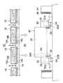
図1は本発明に係る搬送台車の第1の実施形態の一例を模式的に示す側面図であり、図2はその正面図を示している。これらの図に示す搬送台車10は、クリーンルーム12に適した台車である。 FIG. 1 is a side view schematically showing an example of a first embodiment of a transport carriage according to the present invention, and FIG. 2 shows a front view thereof. The
このクリーンルーム12の天井面には格子状の天井フレーム16が吊設されており、天井フレーム16の格子空間には複数のFFU(ファンフィルタユニット)18、18…が配設されている。FFU18は、上下に開口されたケーシング18Aと、上方からエアをケーシング18A内に吸い込んで下方に吹き出すファン18Bと、ケーシング18A内に吸い込まれたエアを除塵するHAPAフィルタ18Cとで構成されており、このFFU18によって天井裏空間20のエアが除塵され、清浄エアとしてクリーンルーム12内にダウンフローされる。 A grid-
クリーンルーム12の床面には、複数の排気口14、14…が形成される。複数の排気口14、14…は、後述のレール24に沿ってレール24の周辺に配置される。また、排気口14は、上下に貫通して形成されており、この排気口14を介して、クリーンルーム12と床下チャンバ22が連通される。したがって、クリーンルーム12内にダウンフローされた清浄エアは、床下空間22に吸い込まれる。これにより、クリーンルーム12内の塵埃が清浄エアのダウンフローによって床下チャンバ22に排出されるので、クリーンルーム12内が高い清浄度に維持される。なお、排気口14は、クリーンルーム12の床面の略全面に形成してもよく、その場合には、レール24の周辺に集中して配置することが好ましい。 A plurality of
床下チャンバ22は、クリーンルーム12の側方に形成されたリターンチャンバ(不図示)を介して天井裏空間20に連通される。したがって、床下チャンバ22のエアは、天井裏空間22に戻され、天井裏空間22から再びFFU18によってクリーンルーム12に吹き出される。これにより、エアが循環され、クリーンルーム12の内部が常に高い清浄度に維持される。 The
クリーンルーム12の床面の上には、レール24、24が敷設されている。レール24、24は、搬送台車10の走行軌道に沿って形成されており、搬送台車10はこのレール24、24上を走行自在となるように構成される。 On the floor surface of the
搬送台車10は主として、台車本体26、車輪28、28…、車輪カバー30で構成される。台車本体26の上部には、不図示の搬送物移載装置が設けられており、この搬送物移載装置によって搬送物を積載して搬送できるようになっている。搬送物移載装置は特に限定するものではないが、たとえばクレーン、コンベア、フォーク等が用いられる。 The
台車本体26の下部には、四個の車輪28、28…が取り付けられている。各車輪28、28…は、台車本体26の側面から側方に突出して配置されており、不図示のモータによって回転駆動される。この車輪28、28…がレール24、24上で回転することによって、搬送台車10がレール24、24に沿って走行される。 Four
車輪28、28…の上部は、車輪カバー30、30…によって覆われている。各車輪カバー30は、台車本体26の側面から突出した状態で、台車本体26の下部に固定される。また、各車輪カバー30は、車輪28の下部を除いて略全体を覆うように形成されており、その下部には下方に向けて開口された吹出口30Aが形成される。さらに、各車輪カバー30の上面には、吸込口30Bが形成されており、その吸込口30Bにファン32が設けられる。ファン32を駆動することによって、吸込口30Bから車輪カバー30の内部にエアが吸引され、そのエアが吹出口30Aから下方に向けて吹き出される。 The upper portions of the
ところで、ファン32は、吹出口30Aから吹き出すエアの流速が、クリーンルーム12に吹き出す清浄エアの気流の流速よりも大きく、且つ、排気口14から排気する排気エアの気流の流速以下になるように、回転数が制御される。なお、清浄エアの気流の流速及び排気エアの気流の流速は、クリーンルーム12の設定(すなわち、FFU18の吹出口の面積や排気口14の面積、FFU18のファン18Bの回転数等)によって予め決まっている。 By the way, the
次に上記の如く構成された搬送台車10の作用について説明する。 Next, the operation of the
搬送台車10を走行させた際、特に搬送台車10を180m/min以上の高速で走行させた際には、車輪28、28…から塵埃が発生する。従来の搬送台車では、この塵埃が巻きあがって製品等に付着するという問題があった。 When the
そこで、本実施の形態の搬送台車10では、ファン32を駆動することによって、吸込口30Bからエアを吸引し、車輪28の周囲の塵埃とともに吹出口30Aから下方に向けて吹き出している。さらに、本実施の形態では、その吹出口30Aから吹き出すエアの流速が、クリーンルーム12に吹き出す清浄エアの気流の流速よりも大きく、且つ、排気口14から排気する排気エアの気流の流速以下になるように制御している。これにより、吹出口30Aから吹き出されたエアは、排気口14に強制的に誘導され、床下空間22に吸い込まれる。よって、吹出口30Aから吹き出されるエアに含まれる塵埃は、周囲に拡散することなく、排気口14に誘導されて床下空間22に排出される。したがって、本実施の形態によれば、塵埃が巻き上がることを防止でき、クリーンルーム10を常に高い清浄度に維持することができる。 Therefore, in the
このように本実施の形態によれば、車輪28の周囲のエアを、吹出口30Aからクリーンルーム12の床面に向けて吹き出すとともに、その流速をクリーンルーム12に吹き出す清浄エアの気流の流速よりも大きく、且つ、排気口14から排気する排気エアの気流の流速以下になるように制御したので、車輪28から発生した塵埃をクリーンルーム12の排気口14から確実に排出することができ、クリーンルーム10を常に高い清浄度に維持することができる。 As described above, according to the present embodiment, the air around the
次に第2の実施形態の搬送台車について説明する。図3は、第2の実施形態の搬送台車40を示す正面図である。第2の実施形態の搬送台車40は、レール24の側方に設けたダクト44の吸気口47を排気口とするクリーンルーム42において搬送に適した台車である。 Next, a transport cart according to a second embodiment will be described. FIG. 3 is a front view showing the
図3に示すように、クリーンルーム42の内部には、レール24、24の外側にダクト44、44が設けられる。各ダクト44は、レール24に沿って配設されており、天井裏空間20に連通されている。また、ダクト44は、レール24に対向する側面に吸気口(排気口に相当)46が形成されており、この吸気口46を介してクリーンルーム42内のエアをダクト44内に吸い込んで天井裏空間20に送気するように構成される。なお、クリーンルーム42の床面は、開口のない平坦面になっており、FFU18からダウンフローされたエアは、床面において吸気口46に向けて流れる気流を形成し、吸気口46からダクト44に吸引される。 As shown in FIG. 3,
搬送台車40は、図2に示した第1の実施形態の搬送台車10と比較した際、第1の実施形態では車輪カバー30の上面に吸込口30B、下面に吹出口30Aが形成されていたのに対し、第2の実施形態では車輪カバー50の外側側面の下部を吹出口50Aとし、車輪カバー50の内側側面の下部を吸込口50Bとしている。そして、吸込口50Bにファン52が設けられ、このファン52を駆動することによって、吸込口50Bから車輪カバー50の内部にエアが吸い込まれ、車輪28の周囲の塵埃とともに吹出口50Aから側方に向けて吹き出される。 When compared with the
ファン52は、吹出口50Aから吹き出すエアの風速が、クリーンルーム12に吹き出す清浄エアの気流の流速よりも大きく、且つ、吸引口(排気口)46から排気する排気エアの気流の流速以下になるように制御される。なお、清浄エアの気流の流速及び排気エアの気流の流速は、クリーンルーム12の設定(すなわち、FFU18の吹出口の面積や吸引口(排気口)46の面積、FFU18のファン18Bの回転数等)によって予め決まっている。 The
なお、図3の右側の車輪カバー50は、ファン52からエアを直接吸い込むように構成した例であり、図3の左側の車輪カバー50は、ファン52にダクト54を接続し、このダクト54を台車本体26の上面の開口26Bに接続することによって、開口26Bからエアを吸引した例である。いずれの形態を用いてもよく、左右両方で同じ形態を採用してもよい。 3 is an example in which air is directly sucked from the
上記の如く構成された搬送台車40の場合にも、吹出口50から吹き出されるエアの流速をクリーンルームに吹き出す清浄エアの気流の流速よりも大きく、且つ、吸引口(排気口)46から排気する排気エアの気流の流速以下にしたので、吹出口50Aから吹き出されたエアに含まれる塵埃は、周囲に拡散することなく、強制的に吸気口46に誘導される。よって、塵埃が巻き上がることを防止でき、クリーンルーム42を常に高い清浄度に維持することができる。 Also in the case of the
次に第3の実施形態の搬送台車について図4に従って説明する。図4に示す第3の実施形態の搬送台車60は、図3に示した第2の実施形態の搬送台車40と比較して、車輪カバー50の吹出口50Aの位置にファン62及びフィルタ64が設けられている点で異なっている。 Next, a transport cart according to a third embodiment will be described with reference to FIG. Compared with the
第3の実施形態によれば、吹出口50Aの位置にフィルタ64が設けられているので、車輪28から発生した塵埃をフィルタ64で除塵することができる。この搬送台車60は、床面に排気口14(図1参照)が形成されたクリーンルーム12にも、ダクト44の吸気口46を排気口とするクリーンルーム42にも使用することができる。 According to the third embodiment, since the
なお、上述した実施形態において、ファン32、52の回転数は、クリーンルーム12、42の状態に応じて適宜変更するようにしてもよい。すなわち、クリーンルーム12、42の清浄エアの気流の流速、排気エアの気流の流速に応じて、ファン32、52の回転数を変更してもよい。その場合、クリーンルーム12、42の制御装置から、清浄エアや排気エアの気流の流速のデータを非接触で適宜受信できるようにすることが好ましい。 In the above-described embodiment, the rotational speeds of the
また、上述した実施形態では、吹出口30A、50Aから常に一定方向にエアを吹き出すようにしたが、クリーンルーム12、42の排気口の位置に応じて自動的に吹出方向を調節するように構成してもよい。たとえば、吹出口30A、50Aに可動式のルーバを設けて風向を調節できるように構成するとともに、クリーンルーム12、42の制御装置等から排気口の位置情報を随時入力するように構成し、その位置情報に応じて風向を自動的に調節してもよい。 In the above-described embodiment, air is always blown out from the
さらに上述した実施形態では、搬送台車10、40、60におけるエアの吹出風量のみを制御するようにしたが、これに限定するものではなく、クリーンルーム12、42側(すなわち、FFU18)の風量を制御するようにしても良い。 Further, in the above-described embodiment, only the air blowing air volume in the
10…搬送台車、12…クリーンルーム、14…排気口、16…天井フレーム、18…FFU、20…天井裏空間、22…床下空間、24…レール、26…台車本体、28…車輪、30…車輪カバー、32…ファン、40…搬送台車、42…クリーンルーム、44…ダクト、46…吸気口、50…車輪カバー、60…搬送台車 DESCRIPTION OF
Claims (4)
Translated fromJapanese前記車輪の近傍に設けた吹出口から、周囲のエアを前記クリーンルームの排気口に向けて吹き出すとともに、前記吹出口から吹き出すエアの流速を、前記クリーンルームに吹き出す清浄エアの気流の流速よりも大きく、且つ、前記排気口から排気する排気エアの気流の流速以下に制御する塵埃防止用気流発生装置を備えたことを特徴とする搬送台車。In a transport cart that travels in a clean room where an airflow of clean air is formed toward the exhaust port, and travels by wheels provided at the bottom of the cart body,
From the air outlet provided in the vicinity of the wheel, the surrounding air is blown out toward the exhaust port of the clean room, and the flow velocity of the air blown out from the air outlet is larger than the flow velocity of the clean air blown out to the clean room, In addition, the transport carriage includes a dust-preventing airflow generation device that controls the flow rate of the exhaust air exhausted from the exhaust port to be equal to or lower than the flow velocity.
前記吹出口は下方に向けて形成されることを特徴とする請求項1に記載の搬送台車。The exhaust port of the clean room is a plurality of openings that are partially provided on the floor surface of the clean room and penetrated up and down,
The transport cart according to claim 1, wherein the air outlet is formed downward.
Priority Applications (1)
| Application Number | Priority Date | Filing Date | Title |
|---|---|---|---|
| JP2007323720AJP2009147163A (en) | 2007-12-14 | 2007-12-14 | Transport cart |
Applications Claiming Priority (1)
| Application Number | Priority Date | Filing Date | Title |
|---|---|---|---|
| JP2007323720AJP2009147163A (en) | 2007-12-14 | 2007-12-14 | Transport cart |
Publications (1)
| Publication Number | Publication Date |
|---|---|
| JP2009147163Atrue JP2009147163A (en) | 2009-07-02 |
Family
ID=40917427
Family Applications (1)
| Application Number | Title | Priority Date | Filing Date |
|---|---|---|---|
| JP2007323720AWithdrawnJP2009147163A (en) | 2007-12-14 | 2007-12-14 | Transport cart |
Country Status (1)
| Country | Link |
|---|---|
| JP (1) | JP2009147163A (en) |
Cited By (2)
| Publication number | Priority date | Publication date | Assignee | Title |
|---|---|---|---|---|
| KR101853376B1 (en) | 2011-09-01 | 2018-04-30 | 세메스 주식회사 | substrate processing apparatus |
| CN114053796A (en)* | 2020-07-31 | 2022-02-18 | 罗泽系统株式会社 | Main frame of storage device |
Citations (4)
| Publication number | Priority date | Publication date | Assignee | Title |
|---|---|---|---|---|
| JPS60166554A (en)* | 1984-02-07 | 1985-08-29 | 株式会社ダイフク | Cart for clean room |
| JPH10181882A (en)* | 1996-12-24 | 1998-07-07 | Toyota Autom Loom Works Ltd | Automatic guided vehicle for clean room |
| JP2004335552A (en)* | 2003-04-30 | 2004-11-25 | Hoya Corp | Clean space maintaining device and method of transporting photomask substrate |
| JP2007045606A (en)* | 2005-08-11 | 2007-02-22 | Murata Mach Ltd | Carriage |
- 2007
- 2007-12-14JPJP2007323720Apatent/JP2009147163A/ennot_activeWithdrawn
Patent Citations (4)
| Publication number | Priority date | Publication date | Assignee | Title |
|---|---|---|---|---|
| JPS60166554A (en)* | 1984-02-07 | 1985-08-29 | 株式会社ダイフク | Cart for clean room |
| JPH10181882A (en)* | 1996-12-24 | 1998-07-07 | Toyota Autom Loom Works Ltd | Automatic guided vehicle for clean room |
| JP2004335552A (en)* | 2003-04-30 | 2004-11-25 | Hoya Corp | Clean space maintaining device and method of transporting photomask substrate |
| JP2007045606A (en)* | 2005-08-11 | 2007-02-22 | Murata Mach Ltd | Carriage |
Cited By (2)
| Publication number | Priority date | Publication date | Assignee | Title |
|---|---|---|---|---|
| KR101853376B1 (en) | 2011-09-01 | 2018-04-30 | 세메스 주식회사 | substrate processing apparatus |
| CN114053796A (en)* | 2020-07-31 | 2022-02-18 | 罗泽系统株式会社 | Main frame of storage device |
Similar Documents
| Publication | Publication Date | Title |
|---|---|---|
| CN202964647U (en) | Transportation robot and equipment front-end module including transportation robot | |
| JP5585236B2 (en) | Tracked cart system | |
| JP2009147163A (en) | Transport cart | |
| JP2009206245A (en) | Device and method for preventing dusting of traveling wheel | |
| JP3882139B2 (en) | Clean transport vehicle | |
| JP2010272828A (en) | LCD substrate storage warehouse room | |
| JP4715383B2 (en) | Transport cart | |
| JP4656296B2 (en) | Local cleaning device and clean room | |
| JP2007276987A (en) | Conveying device | |
| JP2009126677A (en) | Transport device | |
| JP2008297046A (en) | Airflow control method and storage warehouse equipment | |
| JP3637947B2 (en) | Transport equipment | |
| JP6374775B2 (en) | Substrate transfer system and heat treatment apparatus using the same | |
| JP3861534B2 (en) | Automated guided vehicle for clean rooms | |
| CA2702526C (en) | Storage configuration with predeterminable storage atmosphere | |
| JPS5857981B2 (en) | painting booth | |
| TW202035250A (en) | Article transport facility | |
| JP5088591B2 (en) | Plate-shaped body transfer device | |
| JP4067703B2 (en) | Transport cart | |
| JPH10181882A (en) | Automatic guided vehicle for clean room | |
| JP4244389B2 (en) | Clean room equipment | |
| JP2000142417A (en) | Carrying car | |
| JPS63304640A (en) | Transfer equipment in clean room | |
| JP2000269296A (en) | Rail of carriage for clean room | |
| JPH07310941A (en) | Clean room |
Legal Events
| Date | Code | Title | Description |
|---|---|---|---|
| A621 | Written request for application examination | Free format text:JAPANESE INTERMEDIATE CODE: A621 Effective date:20100302 | |
| A977 | Report on retrieval | Free format text:JAPANESE INTERMEDIATE CODE: A971007 Effective date:20110224 | |
| A131 | Notification of reasons for refusal | Free format text:JAPANESE INTERMEDIATE CODE: A131 Effective date:20110302 | |
| A761 | Written withdrawal of application | Free format text:JAPANESE INTERMEDIATE CODE: A761 Effective date:20110324 |