JP2009144121A - Coke oven coke extruder and extrusion method - Google Patents
Coke oven coke extruder and extrusion methodDownload PDFInfo
- Publication number
- JP2009144121A JP2009144121AJP2007325743AJP2007325743AJP2009144121AJP 2009144121 AJP2009144121 AJP 2009144121AJP 2007325743 AJP2007325743 AJP 2007325743AJP 2007325743 AJP2007325743 AJP 2007325743AJP 2009144121 AJP2009144121 AJP 2009144121A
- Authority
- JP
- Japan
- Prior art keywords
- coke
- carbon
- extruder
- carbonization chamber
- coke oven
- Prior art date
- Legal status (The legal status is an assumption and is not a legal conclusion. Google has not performed a legal analysis and makes no representation as to the accuracy of the status listed.)
- Withdrawn
Links
Images

Landscapes
- Coke Industry (AREA)
Abstract
Translated fromJapaneseDescription
Translated fromJapanese本発明は、コークス炉のコークス押出機及び押出方法、特に、炭化室の天井と炉壁に付着したカーボンを除去する装置を備えたコークス押出機、及び、該コークス押出機を用いたコークス押出方法に関する。 The present invention relates to a coke extruder for a coke oven and an extrusion method, in particular, a coke extruder equipped with a device for removing carbon adhering to the ceiling and furnace wall of a carbonization chamber, and a coke extrusion method using the coke extruder. About.
コークス炉の炭化室内で石炭を乾留しコークスを製造するとき、炭化水素系ガスが発生する。炭化水素系ガスは、炭化室の上昇管から排出されるが、炭化水素系ガスが、炭化室上部の空間を通過し上昇管に達するまでの間に、該ガスが熱分解してカーボン(固体)が発生し、炭化室の天井及び炉壁に付着する。 Hydrocarbon-based gas is generated when coke is produced by carbonizing in the carbonization chamber of a coke oven. The hydrocarbon-based gas is exhausted from the riser pipe of the carbonization chamber, but the hydrocarbon-based gas is thermally decomposed by the time it passes through the space above the carbonization chamber and reaches the riser pipe. ) Occurs and adheres to the ceiling and furnace wall of the carbonization chamber.
コークス炉の炭化室の内部に付着するカーボンは、初期は、スポンジ状(気孔が多い)であり、酸素含有気体の導入による燃焼や、機械的手段で簡単に除去することができるが、石炭の乾留を繰り返す(炭化室内への石炭の装入と排出を繰り返す)うちに、カーボンが気孔内へ浸入して堆積し、スポンジ状のカーボンは、次第に、硬質なカーボンとなる。 The carbon adhering to the inside of the carbonization chamber of the coke oven is initially sponge-like (has many pores) and can be easily removed by combustion by introducing an oxygen-containing gas or by mechanical means. During repeated carbonization (repeating charging and discharging of coal into the carbonization chamber), carbon enters and accumulates in the pores, and the sponge-like carbon gradually becomes hard carbon.
カーボンが炭化室の天井や炉壁に付着し堆積すると、炭化室上部空間の通気性が悪化して、炭化水素系ガスからカーボンが生成し易くなり、また、コークスを押し出す時の障害となる。また、カーボンが硬質化すると、コークスを押し出す際、押出機のラムヘッドの蛇行の程度が大きくなり、ラムヘッドを押し出す力が増大するし、また、炭化室の炉壁が損傷することがある。 If carbon adheres to and accumulates on the ceiling or furnace wall of the carbonization chamber, the air permeability of the upper space of the carbonization chamber deteriorates, carbon is easily generated from the hydrocarbon-based gas, and becomes an obstacle when extruding coke. Further, when the carbon is hardened, when the coke is extruded, the degree of meandering of the ram head of the extruder is increased, the force of pushing out the ram head is increased, and the furnace wall of the carbonization chamber may be damaged.
それ故、炭化室の天井及び炉壁に付着したカーボンを除去する装置及び方法が、これまで、数多く提案されている。これら提案は、採用するカーボン除去手段及び手法の点で、大きく、次ぎの三つに分類することができる。 Therefore, many devices and methods for removing carbon adhering to the ceiling and furnace wall of the carbonization chamber have been proposed so far. These proposals can be broadly classified into the following three types in terms of the carbon removal means and methods employed.
(1) カーボンカッター(カーボンスクレーパー)、又は、掻板で、カーボンを掻き落とす方式(接触方式)(例えば、実開昭58−34935号公報、特開2001−200258号公報)
(2) 音響発信装置で低周波音を発生させ、音圧でカーボンを除去する方式(非接触方式)(例えば、特開平2−24392号公報)
(3) 酸素含有気体又は空気によりカーボンを燃焼させて除去する方式(非接触方式)(例えば、特開昭59−25879号公報、特開2006−124559号公報、特開2007−70527号公報、特開2007−119577号公報、特開2007−169533号)(1) A method (contact method) in which carbon is scraped off with a carbon cutter (carbon scraper) or a scraper (for example, Japanese Utility Model Laid-Open No. 58-34935 and Japanese Patent Application Laid-Open No. 2001-200258).
(2) A method of generating low-frequency sound with an acoustic transmission device and removing carbon with sound pressure (non-contact method) (for example, JP-A-2-24392)
(3) A method in which carbon is burned and removed by an oxygen-containing gas or air (non-contact method) (for example, JP 59-25879, JP 2006-124559, JP 2007-70527, (Japanese Unexamined Patent Application Publication Nos. 2007-119557 and 2007-169533)
上記(1)の方式によれば、簡単な構造の機械的手段で、カーボン除去を効率的に行うことができるが、炭化室の長手方向の付着カーボン量(厚み)が不均一であると、カーボン除去量も不均一となり、ラムヘッドが前進する際、炉幅方向に蛇行し、炉壁煉瓦を壊す危険がある。 According to the above method (1), carbon can be efficiently removed by mechanical means having a simple structure, but the amount of carbon attached (thickness) in the longitudinal direction of the carbonization chamber is non-uniform. The amount of carbon removal becomes uneven, and when the ram head moves forward, there is a danger of meandering in the furnace width direction and breaking the furnace wall brick.
上記(2)の方式によれば、カーボン除去装置が大がかりなものとならざるを得ず、設備費が上昇して、コークスの製造コストを押し上げる。 According to the above method (2), the carbon removal device must be large, and the equipment cost rises, which increases the production cost of coke.
上記(3)の方式によれば、カーボンの除去に時間がかかるので、コークス炉の稼働率が高い場合には、十分なカーボン除去効果を期待することができない。 According to the above method (3), since it takes time to remove carbon, when the operating rate of the coke oven is high, a sufficient carbon removal effect cannot be expected.
本発明は、コークス炉に係るカーボン除去技術の現状に鑑み、構造が簡単な機械的手段を用いることを前提に、(i)炭化室の長手方向において除去されずに残る付着カーボン量(厚み)が均一になるように、カーボンを除去し、(ii)ラムヘッドの前進時における炉幅方向の蛇行を抑制することを課題とする。 In view of the current state of carbon removal technology related to a coke oven, the present invention is based on the premise that mechanical means with a simple structure is used. (I) Amount of attached carbon (thickness) remaining without being removed in the longitudinal direction of the carbonization chamber It is an object to remove the carbon so as to be uniform, and (ii) suppress meandering in the furnace width direction when the ram head advances.
そして、本発明は、上記課題を解決するカーボン除去構造を備えるコークス押出機を提供することを目的とする。 And this invention aims at providing the coke extruder provided with the carbon removal structure which solves the said subject.
本発明者らは、炭化室の炉壁に付着、堆積したカーボンを機械的手段で除去する際、カーボンが硬質化していると、炭化室の長手方向におけるカーボン除去量が不均一になることから、硬質化したカーボンを、何らかの手段又は手法で脆弱化すれば、上記(i)の課題を解決することができると発想し、上記脆弱化手段及び手法について鋭意検討した。 When removing carbon adhering to and depositing on the furnace wall of the carbonization chamber by mechanical means, the carbon removal amount in the longitudinal direction of the carbonization chamber becomes non-uniform when the carbon is hardened. The idea that the above problem (i) can be solved if the hardened carbon is weakened by any means or technique, and the above-described weakening means and technique have been studied earnestly.
その結果、本発明者らは、コークス押出機のラムヘッドの上部に設けた掻板(ラムヘッドの前進時、炭化室の天井と炉壁に付着したカーボンを掻き取る)の前面に、円周面に突起を有する円筒管を配置し、コークスの押出時、円筒管を、炭化室の天井と炉壁に付着して硬質化したカーボンに接触させて回転させると、円筒管の突起による穿孔で、硬質化カーボンが脆弱化し、掻板との接触で、簡単に脱落することを見出した。 As a result, the inventors of the present invention, on the circumferential surface, on the front surface of a scraper provided on the top of the ram head of the coke extruder (scraping carbon adhering to the ceiling and furnace wall of the carbonization chamber when the ram head advances). When a cylindrical tube with protrusions is placed, and the coke is extruded, the cylindrical tube comes into contact with the hardened carbon that adheres to the ceiling and furnace wall of the carbonization chamber and is rotated. It was found that the carbonized carbon becomes brittle and easily drops off when it comes into contact with the scraper.
また、本発明者らは、円筒管の突起による穿孔とともに、円筒管から、酸素含有気体を、硬質化カーボンに吹き付けると、酸素含有気体は、穿孔された孔から、カーボン内部まで侵入して、硬質化したカーボンを、効率的に燃焼させて、除去することができることを見出した。 Further, the present inventors, along with the perforations by the projections of the cylindrical tube, when the oxygen-containing gas is blown from the cylindrical tube to the hardened carbon, the oxygen-containing gas penetrates from the perforated holes to the inside of the carbon, It has been found that the hardened carbon can be efficiently burned and removed.
本発明は、上記知見に基づいてなされたもので、その要旨は以下のとおりである。 This invention was made | formed based on the said knowledge, and the summary is as follows.
(1) 炭化室からコークスを押し出すラムヘッドの上部に、炭化室の天井と炉壁に付着したカーボンを除去する掻板を備えたコークス炉のコークス押出機において、
(a)上記掻板の前方上部に、円周面に突起を有し、炭化室の炉天井に付着したカーボンに接触して回転する円筒管を、水平に配置し、
(b)上記掻板の前方左右に、円周面に突起を有し、炭化室の炉壁に付着したカーボンに接触して回転する円筒管を、垂直に配置した
ことを特徴とするコークス炉のコークス押出機。(1) In a coke extruder for a coke oven provided with a scraper that removes carbon adhering to the ceiling and furnace wall of the coking chamber at the upper part of the ram head that extrudes coke from the carbonizing chamber.
(A) A cylindrical tube that has a protrusion on the circumferential surface and rotates in contact with the carbon adhering to the furnace ceiling of the carbonization chamber is disposed horizontally on the front upper portion of the scraper,
(B) A coke oven characterized in that cylindrical pipes having protrusions on the circumferential surface and rotating in contact with the carbon adhering to the furnace wall of the carbonization chamber are vertically arranged on the front left and right of the scraper. Coke extruder.
(2) 前記突起が、円錐状の突起であることを特徴とする前記(1)に記載のコークス炉のコークス押出機。 (2) The coke extruder for a coke oven according to (1), wherein the protrusion is a conical protrusion.
(3) 前記円筒管が、中空構造で、かつ、円周面に複数の開口を有することを特徴とする前記(1)又は(2)に記載のコークス炉のコークス押出機。 (3) The coke extruder for a coke oven according to (1) or (2), wherein the cylindrical tube has a hollow structure and has a plurality of openings on a circumferential surface.
(4) 前記円筒管に、気体を供給する配管が接続されていることを特徴とする前記(1)〜(3)のいずれかに記載のコークス炉のコークス押出機。 (4) The coke extruder for a coke oven according to any one of (1) to (3), wherein a pipe for supplying a gas is connected to the cylindrical tube.
(5) 前記円筒管が、該円筒管に接続された配管を軸にして回転することを特徴とする前記(4)に記載のコークス炉のコークス押出機。 (5) The coke extruder for a coke oven according to (4), wherein the cylindrical pipe rotates around a pipe connected to the cylindrical pipe.
(6) 前記配管が、圧縮気体を供給する装置に接続されていることを特徴とする前記(3)〜(5)のいずれかに記載のコークス炉のコークス押出機。 (6) The coke extruder for a coke oven according to any one of (3) to (5), wherein the pipe is connected to a device that supplies compressed gas.
(7) 前記圧縮気体が、酸素含有気体であることを特徴とする前記(6)に記載のコークス炉のコークス押出機。 (7) The coke extruder for a coke oven according to (6), wherein the compressed gas is an oxygen-containing gas.
(8) コークス押出機で炭化室内のコークスを押し出すコークス炉の押出方法において、前記(1)〜(7)のいずれかに記載のコークス炉のコークス押出機を用い、炭化室からコークスを押し出すとともに、炭化室の天井及び炉壁に付着したカーボンを除去することを特徴とするコークス炉のコークス押出方法。 (8) In the coke oven extrusion method for extruding coke in the carbonization chamber using a coke extruder, the coke extruder for the coke oven according to any one of (1) to (7) above is used to extrude coke from the carbonization chamber. A coke extrusion method for a coke oven, wherein carbon adhering to a ceiling and a furnace wall of a carbonization chamber is removed.
(9) 前記(8)に記載のコークス炉のコークス押出方法において、円筒管に酸素含有気体を供給することを特徴とするコークス炉のコークス押出方法。 (9) The coke extrusion method for a coke oven according to (8), wherein an oxygen-containing gas is supplied to the cylindrical tube.
本発明によれば、コークスの押出時、コークス押出機のラムビームが一往復する間に、炭化室の天井と炉壁に付着したカーボンを、効率よく除去することができる。その結果、コークス炉の生産性は低下せず、かつ、炉体に対する負荷が低減するので、コークス炉の寿命が延びる。 According to the present invention, carbon adhering to the ceiling and furnace wall of the coking chamber can be efficiently removed while the ram beam of the coke extruder makes one reciprocation during the coke extrusion. As a result, the productivity of the coke oven does not decrease and the load on the furnace body is reduced, so that the life of the coke oven is extended.
本発明について、図面に基づいて説明する。 The present invention will be described with reference to the drawings.
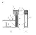
図1に、コークス炉の炭化室内にラムヘッドを押し込む、従来のコークス押出態様を示す。図1(a)は、側面の部分態様を示し、図1(b)は、正面態様を示す。 FIG. 1 shows a conventional coke extrusion mode in which a ram head is pushed into a carbonization chamber of a coke oven. Fig.1 (a) shows the partial aspect of a side surface, FIG.1 (b) shows a front aspect.
コークス炉の炭化室1は、煉瓦で構築された炉天井2、炉壁3、及び、炉底4で構成されている。コークス押出機5は、ラムシュー7を備えたラムビーム6と、ラムビーム6の先端に取り付けられたラムヘッド8からなり、ラムヘッド8の上部には、掻板9が取り付けられている。 The carbonizing
炭化室1内に、ラムヘッド8を押し込んでコークス10を押し出す時、掻板9が、炉天井2と、炉天井2に続く炉壁3に付着したカーボン11に接触して、カーボン11を掻き落とす。 When the
ラムヘッド8を押し込んでコークス10を押し出す時、カーボン11が硬質化していると、掻板9による掻き落としカーボン量が不均一となる。不均一な掻き落としが続くと、炉壁3に残存するカーボン厚の不均一が顕著になり、ラムヘッド8は、コークス10を押し出すときに、蛇行するようになる。 When the
ラムヘッドが蛇行すると、特に、ラムヘッドの上部、炭化室の炉壁に強く接触して、炉壁煉瓦を壊すなど、コークス炉操業において重大なトラブルを引き起こすことになる。それ故、炉天井と炉壁に付着している硬質カーボンを均一に掻き落とし、炉天井と炉壁に残存するカーボン層の厚みを、常に、均一に維持する必要がある。 If the ram head meanders, it will cause serious troubles in coke oven operation, in particular, strong contact with the upper part of the ram head, the furnace wall of the carbonization chamber, and breaking the bricks of the furnace wall. Therefore, it is necessary to evenly scrape the hard carbon adhering to the furnace ceiling and the furnace wall, and to keep the thickness of the carbon layer remaining on the furnace ceiling and the furnace wall always uniform.
そこで、本発明のコークス押出機(本発明押出機)においては、図2に示すように、コークスの押し出し方向Dを前方として、(a)ラムヘッド8の上部に設けた掻板9の前方上部に、円周面に突起を有し、炭化室の炉天井に付着したカーボンに接触して軸13を中心にして回転する円筒管12を、水平に配置し、かつ、(b)上記掻板9の前方左右に、円周面に突起を有し、炭化室の炉壁に付着したカーボンに接触して軸13を中心にして回転する円筒管12を、垂直に配置する。 Therefore, in the coke extruder of the present invention (extruder of the present invention), as shown in FIG. 2, the coke extrusion direction D is the front, and (a) the
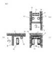
図3に、掻板の前方上部及び前方左右に配置した円筒管と、後続の掻板が協働して、炭化室の炉天井及び炉壁に付着したカーボンを掻き落とす態様を示す。図3(a)は、上方からみた掻板9と円筒管12の位置関係を示し、図3(b)は、側方からみた掻板9と円筒管12の位置関係を示し、図3(c)は、押し出し方向でみた掻板9と円筒管12の位置関係を示す。 FIG. 3 shows a mode in which the cylindrical pipes arranged at the front upper part and the front left and right of the scraper and the subsequent scraper cooperate to scrape off carbon adhering to the furnace ceiling and furnace wall of the carbonization chamber. 3A shows the positional relationship between the
ラムヘッドを前進させ、掻板9の前方上部及び左右に配置した、円錐状の突起14を有する円筒管12を、炭化室の炉天井2と炉壁3に付着したカーボン11に押し付けて回転させると、円錐状の突起14が、カーボン11に食い込んで、カーボン11の表面に孔が形成される。 When the ram head is advanced and the
この結果、硬質化したカーボン11は脆弱となり、後続の掻板9が、カーボン11に接触した時、カーボン11は簡単に脱落する。 As a result, the hardened
このように、掻板の前方上部及び前方左右に配置した円筒管と、後続の掻板が協働して、炭化室の炉天井及び炉壁に付着したカーボンを掻き落とす。この点が、本発明押出機の特徴である。 In this way, the cylindrical tubes disposed on the upper front part and the front left and right of the scraper cooperate with the subsequent scraper to scrape off carbon adhering to the furnace ceiling and furnace wall of the carbonization chamber. This is a feature of the extruder of the present invention.
図3には、円周面に円錐状の突起を有する円筒管を示したが、突起の形状は、炭化室の炉天井及び炉壁に付着したカーボンに、容易に孔を形成することができるように、先端が先鋭的なものであればよく、円錐状に限定されない。 Although FIG. 3 shows a cylindrical tube having a conical protrusion on the circumferential surface, the protrusion can easily form a hole in carbon attached to the furnace ceiling and furnace wall of the carbonization chamber. As such, the tip may be sharp, and is not limited to a conical shape.
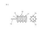
また、円筒管も、図3に示す円筒管に限定されない。図4に、円筒管の別の態様を示す。図4に示す円筒管は、中空構造の円筒管で、軸13が、気体を供給する配管を兼ねていて、円周面に、突起14と開口15が形成されている。 Further, the cylindrical tube is not limited to the cylindrical tube shown in FIG. FIG. 4 shows another embodiment of the cylindrical tube. The cylindrical tube shown in FIG. 4 is a hollow cylindrical tube, the
円筒管12の内部に、配管を経て気体、好ましくは、酸素含有気体を供給すると、開口15から、酸素含有気体が吹き出るが、付着カーボンの表面には、突起14で孔15が形成されているので、円筒管12の開口15から吹き出た酸素含有気体は、付着カーボンの内部まで侵入して、カーボンを燃焼させ、カーボンの除去に貢献する。 When a gas, preferably an oxygen-containing gas, is supplied to the inside of the
このように、突起を有する円筒管に、酸素含有気体が吹き出る開口を設けると、付着カーボンを機械的に除去する効果に、燃焼させて除去する効果が重畳するので、炭化室の炉天井及び炉壁に付着したカーボンを、より効率的に除去することができる。 In this way, if an opening through which oxygen-containing gas blows out is provided in the cylindrical tube having the protrusions, the effect of burning and removing is superimposed on the effect of removing adhering carbon mechanically. Carbon adhering to the wall can be removed more efficiently.
また、軸13を通して気体を供給し円筒管12の開口15から気体を噴射することは、軸13と円筒管12を空冷する効果を発現するので、コークス炉の炭化室内の高温条件(例えば、1000℃)下で使用する上記部材の耐久性を高めることになる。 In addition, supplying gas through the
なお、酸素含有気体は、圧縮気体として、配管から円筒管に供給するのが好ましい。通常、酸素含有気体として空気を用いるが、カーボンの燃焼除去の点から、酸素富化空気が好ましい。 The oxygen-containing gas is preferably supplied as a compressed gas from the pipe to the cylindrical tube. Usually, air is used as the oxygen-containing gas, but oxygen-enriched air is preferable from the viewpoint of carbon combustion removal.
次に、本発明の実施例について説明するが、実施例の条件は、本発明の実施可能性及び効果を確認するために採用した一条件例であり、本発明は、この一条件例に限定されるものではない。本発明は、本発明の要旨を逸脱せず、本発明の目的を達成する限りにおいて、種々の条件を採用し得るものである。 Next, examples of the present invention will be described. The conditions of the examples are one example of conditions adopted for confirming the feasibility and effects of the present invention, and the present invention is limited to this one example of conditions. Is not to be done. The present invention can adopt various conditions as long as the object of the present invention is achieved without departing from the gist of the present invention.
(実施例)
従来のコークス押出機と本発明押出機を交互に用いて、コークス炉を操業し、コークス押出機モーターを駆動する最大電流値を測定した。(Example)
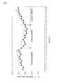
Using the conventional coke extruder and the inventive extruder alternately, the coke oven was operated and the maximum current value for driving the coke extruder motor was measured.
図5に、その結果を示す。図中、本発明未実施期間は、従来のコークス押出機を用いた期間であり、本発明実施期間は、本発明押出機を用いた期間である。なお、縦軸は、炉団の日平均値である。 FIG. 5 shows the result. In the figure, the present invention non-implementation period is a period using a conventional coke extruder, and the present invention implementation period is a period using the present invention extruder. In addition, a vertical axis | shaft is a daily average value of a furnace group.
本発明未実施期間においては、最大電流値が増加傾向にある。このことは、炭化室の炉天井及び炉壁に付着したカーボンを充分に除去できず、残存カーボンが硬質化して、コークス押し出し抵抗が増加したと考えられる。 In the period when the present invention is not implemented, the maximum current value tends to increase. This is considered to be because carbon adhering to the furnace ceiling and furnace wall of the carbonization chamber could not be sufficiently removed, the remaining carbon became hard, and the coke extrusion resistance increased.
本発明押出機を用いると、コークス押出機モーターを駆動する最大電流値は低下し始めた。このことは、本発明押出機が備える円筒管が機能して、炭化室の炉天井及び炉壁に付着したカーボンを充分に除去することでき、コークス押し出し抵抗が減少したと考えられる。 When the extruder of the present invention was used, the maximum current value for driving the coke extruder motor began to decrease. This is considered to be because the cylindrical tube provided in the extruder of the present invention functions to sufficiently remove carbon adhering to the furnace ceiling and furnace wall of the carbonization chamber, and the coke extrusion resistance is reduced.
再度、従来のコークス押出機を用いると、コークス押出機モーターを駆動する最大電流値は、増加し始めた。このように、本発明押出機の効果を確認することができた。 Again, using a conventional coke extruder, the maximum current value driving the coke extruder motor began to increase. Thus, the effect of the extruder of the present invention could be confirmed.
前述したように、本発明によれば、コークスの押出時、炭化室の天井と炉壁に付着したカーボンを、効率よく除去することができる。その結果、コークス炉の生産性は低下せず、かつ、炉体に対する負荷が低減するので、コークス炉の寿命が延びる。 As described above, according to the present invention, carbon adhering to the ceiling and the furnace wall of the carbonization chamber can be efficiently removed during coke extrusion. As a result, the productivity of the coke oven does not decrease and the load on the furnace body is reduced, so that the life of the coke oven is extended.
したがって、本発明は、コークス製造産業において利用可能性が高いものである。 Therefore, the present invention has high applicability in the coke manufacturing industry.
1 炭化室
2 炉天井
3 炉壁
4 炉底
5 コークス押出機
6 ラムビーム
7 ラムシュー
8 ラムヘッド
9 掻板
10 コークス
11 カーボン
12 円筒管
13 軸
14 突起
15 開口
D 押し出し方向DESCRIPTION OF
Claims (9)
Translated fromJapanese(a)上記掻板の前方上部に、円周面に突起を有し、炭化室の炉天井に付着したカーボンに接触して回転する円筒管を、水平に配置し、
(b)上記掻板の前方左右に、円周面に突起を有し、炭化室の炉壁に付着したカーボンに接触して回転する円筒管を、垂直に配置した
ことを特徴とするコークス炉のコークス押出機。In the coke extruder of the coke oven equipped with a scraper that removes carbon adhering to the ceiling and furnace wall of the carbonization chamber at the top of the ram head that extrudes coke from the carbonization chamber,
(A) A cylindrical tube that has a protrusion on the circumferential surface and rotates in contact with the carbon adhering to the furnace ceiling of the carbonization chamber is disposed horizontally on the front upper portion of the scraper,
(B) A coke oven characterized in that cylindrical pipes having protrusions on the circumferential surface and rotating in contact with the carbon adhering to the furnace wall of the carbonization chamber are vertically arranged on the front left and right of the scraper. Coke extruder.
Priority Applications (1)
| Application Number | Priority Date | Filing Date | Title |
|---|---|---|---|
| JP2007325743AJP2009144121A (en) | 2007-12-18 | 2007-12-18 | Coke oven coke extruder and extrusion method |
Applications Claiming Priority (1)
| Application Number | Priority Date | Filing Date | Title |
|---|---|---|---|
| JP2007325743AJP2009144121A (en) | 2007-12-18 | 2007-12-18 | Coke oven coke extruder and extrusion method |
Publications (1)
| Publication Number | Publication Date |
|---|---|
| JP2009144121Atrue JP2009144121A (en) | 2009-07-02 |
Family
ID=40915102
Family Applications (1)
| Application Number | Title | Priority Date | Filing Date |
|---|---|---|---|
| JP2007325743AWithdrawnJP2009144121A (en) | 2007-12-18 | 2007-12-18 | Coke oven coke extruder and extrusion method |
Country Status (1)
| Country | Link |
|---|---|
| JP (1) | JP2009144121A (en) |
Cited By (42)
| Publication number | Priority date | Publication date | Assignee | Title |
|---|---|---|---|---|
| WO2015103414A1 (en)* | 2013-12-31 | 2015-07-09 | Suncoke Technology And Development Llc | Methods for decarbonizing coking ovens, and associated systems and devices |
| US9169439B2 (en) | 2012-08-29 | 2015-10-27 | Suncoke Technology And Development Llc | Method and apparatus for testing coal coking properties |
| US9193913B2 (en) | 2012-09-21 | 2015-11-24 | Suncoke Technology And Development Llc | Reduced output rate coke oven operation with gas sharing providing extended process cycle |
| US9193915B2 (en) | 2013-03-14 | 2015-11-24 | Suncoke Technology And Development Llc. | Horizontal heat recovery coke ovens having monolith crowns |
| US9200225B2 (en) | 2010-08-03 | 2015-12-01 | Suncoke Technology And Development Llc. | Method and apparatus for compacting coal for a coal coking process |
| US9238778B2 (en) | 2012-12-28 | 2016-01-19 | Suncoke Technology And Development Llc. | Systems and methods for improving quenched coke recovery |
| US9243186B2 (en) | 2012-08-17 | 2016-01-26 | Suncoke Technology And Development Llc. | Coke plant including exhaust gas sharing |
| US9249357B2 (en) | 2012-08-17 | 2016-02-02 | Suncoke Technology And Development Llc. | Method and apparatus for volatile matter sharing in stamp-charged coke ovens |
| US9273250B2 (en) | 2013-03-15 | 2016-03-01 | Suncoke Technology And Development Llc. | Methods and systems for improved quench tower design |
| US9273249B2 (en) | 2012-12-28 | 2016-03-01 | Suncoke Technology And Development Llc. | Systems and methods for controlling air distribution in a coke oven |
| US9321965B2 (en) | 2009-03-17 | 2016-04-26 | Suncoke Technology And Development Llc. | Flat push coke wet quenching apparatus and process |
| US9359554B2 (en) | 2012-08-17 | 2016-06-07 | Suncoke Technology And Development Llc | Automatic draft control system for coke plants |
| US9476547B2 (en) | 2012-12-28 | 2016-10-25 | Suncoke Technology And Development Llc | Exhaust flow modifier, duct intersection incorporating the same, and methods therefor |
| US9580656B2 (en) | 2014-08-28 | 2017-02-28 | Suncoke Technology And Development Llc | Coke oven charging system |
| US9683740B2 (en) | 2012-07-31 | 2017-06-20 | Suncoke Technology And Development Llc | Methods for handling coal processing emissions and associated systems and devices |
| US10016714B2 (en) | 2012-12-28 | 2018-07-10 | Suncoke Technology And Development Llc | Systems and methods for removing mercury from emissions |
| US10047295B2 (en) | 2012-12-28 | 2018-08-14 | Suncoke Technology And Development Llc | Non-perpendicular connections between coke oven uptakes and a hot common tunnel, and associated systems and methods |
| US10526542B2 (en) | 2015-12-28 | 2020-01-07 | Suncoke Technology And Development Llc | Method and system for dynamically charging a coke oven |
| US10526541B2 (en) | 2014-06-30 | 2020-01-07 | Suncoke Technology And Development Llc | Horizontal heat recovery coke ovens having monolith crowns |
| US10760002B2 (en) | 2012-12-28 | 2020-09-01 | Suncoke Technology And Development Llc | Systems and methods for maintaining a hot car in a coke plant |
| US10851306B2 (en) | 2017-05-23 | 2020-12-01 | Suncoke Technology And Development Llc | System and method for repairing a coke oven |
| US10883051B2 (en) | 2012-12-28 | 2021-01-05 | Suncoke Technology And Development Llc | Methods and systems for improved coke quenching |
| US10968395B2 (en) | 2014-12-31 | 2021-04-06 | Suncoke Technology And Development Llc | Multi-modal beds of coking material |
| US10968393B2 (en) | 2014-09-15 | 2021-04-06 | Suncoke Technology And Development Llc | Coke ovens having monolith component construction |
| US11008518B2 (en) | 2018-12-28 | 2021-05-18 | Suncoke Technology And Development Llc | Coke plant tunnel repair and flexible joints |
| US11021655B2 (en) | 2018-12-28 | 2021-06-01 | Suncoke Technology And Development Llc | Decarbonization of coke ovens and associated systems and methods |
| US11060032B2 (en) | 2015-01-02 | 2021-07-13 | Suncoke Technology And Development Llc | Integrated coke plant automation and optimization using advanced control and optimization techniques |
| US11071935B2 (en) | 2018-12-28 | 2021-07-27 | Suncoke Technology And Development Llc | Particulate detection for industrial facilities, and associated systems and methods |
| US11098252B2 (en) | 2018-12-28 | 2021-08-24 | Suncoke Technology And Development Llc | Spring-loaded heat recovery oven system and method |
| US11142699B2 (en) | 2012-12-28 | 2021-10-12 | Suncoke Technology And Development Llc | Vent stack lids and associated systems and methods |
| US11261381B2 (en) | 2018-12-28 | 2022-03-01 | Suncoke Technology And Development Llc | Heat recovery oven foundation |
| US11395989B2 (en) | 2018-12-31 | 2022-07-26 | Suncoke Technology And Development Llc | Methods and systems for providing corrosion resistant surfaces in contaminant treatment systems |
| US11486572B2 (en) | 2018-12-31 | 2022-11-01 | Suncoke Technology And Development Llc | Systems and methods for Utilizing flue gas |
| US11508230B2 (en) | 2016-06-03 | 2022-11-22 | Suncoke Technology And Development Llc | Methods and systems for automatically generating a remedial action in an industrial facility |
| US11760937B2 (en) | 2018-12-28 | 2023-09-19 | Suncoke Technology And Development Llc | Oven uptakes |
| US11767482B2 (en) | 2020-05-03 | 2023-09-26 | Suncoke Technology And Development Llc | High-quality coke products |
| US11788012B2 (en) | 2015-01-02 | 2023-10-17 | Suncoke Technology And Development Llc | Integrated coke plant automation and optimization using advanced control and optimization techniques |
| US11851724B2 (en) | 2021-11-04 | 2023-12-26 | Suncoke Technology And Development Llc. | Foundry coke products, and associated systems, devices, and methods |
| US11946108B2 (en) | 2021-11-04 | 2024-04-02 | Suncoke Technology And Development Llc | Foundry coke products and associated processing methods via cupolas |
| US12110458B2 (en) | 2022-11-04 | 2024-10-08 | Suncoke Technology And Development Llc | Coal blends, foundry coke products, and associated systems, devices, and methods |
| US12227699B2 (en) | 2019-12-26 | 2025-02-18 | Suncoke Technology And Development Llc | Oven health optimization systems and methods |
| US12410369B2 (en) | 2023-11-21 | 2025-09-09 | Suncoke Technology And Development Llc | Flat push hot car for foundry coke and associated systems and methods |
- 2007
- 2007-12-18JPJP2007325743Apatent/JP2009144121A/ennot_activeWithdrawn
Cited By (89)
| Publication number | Priority date | Publication date | Assignee | Title |
|---|---|---|---|---|
| US9321965B2 (en) | 2009-03-17 | 2016-04-26 | Suncoke Technology And Development Llc. | Flat push coke wet quenching apparatus and process |
| US9200225B2 (en) | 2010-08-03 | 2015-12-01 | Suncoke Technology And Development Llc. | Method and apparatus for compacting coal for a coal coking process |
| US9683740B2 (en) | 2012-07-31 | 2017-06-20 | Suncoke Technology And Development Llc | Methods for handling coal processing emissions and associated systems and devices |
| US9243186B2 (en) | 2012-08-17 | 2016-01-26 | Suncoke Technology And Development Llc. | Coke plant including exhaust gas sharing |
| US11441077B2 (en) | 2012-08-17 | 2022-09-13 | Suncoke Technology And Development Llc | Coke plant including exhaust gas sharing |
| US11692138B2 (en) | 2012-08-17 | 2023-07-04 | Suncoke Technology And Development Llc | Automatic draft control system for coke plants |
| US10041002B2 (en) | 2012-08-17 | 2018-08-07 | Suncoke Technology And Development Llc | Coke plant including exhaust gas sharing |
| US9249357B2 (en) | 2012-08-17 | 2016-02-02 | Suncoke Technology And Development Llc. | Method and apparatus for volatile matter sharing in stamp-charged coke ovens |
| US12195671B2 (en) | 2012-08-17 | 2025-01-14 | Suncoke Technology And Development Llc | Automatic draft control system for coke plants |
| US10947455B2 (en) | 2012-08-17 | 2021-03-16 | Suncoke Technology And Development Llc | Automatic draft control system for coke plants |
| US9359554B2 (en) | 2012-08-17 | 2016-06-07 | Suncoke Technology And Development Llc | Automatic draft control system for coke plants |
| US10611965B2 (en) | 2012-08-17 | 2020-04-07 | Suncoke Technology And Development Llc | Coke plant including exhaust gas sharing |
| US10053627B2 (en) | 2012-08-29 | 2018-08-21 | Suncoke Technology And Development Llc | Method and apparatus for testing coal coking properties |
| US9169439B2 (en) | 2012-08-29 | 2015-10-27 | Suncoke Technology And Development Llc | Method and apparatus for testing coal coking properties |
| US9193913B2 (en) | 2012-09-21 | 2015-11-24 | Suncoke Technology And Development Llc | Reduced output rate coke oven operation with gas sharing providing extended process cycle |
| US11008517B2 (en) | 2012-12-28 | 2021-05-18 | Suncoke Technology And Development Llc | Non-perpendicular connections between coke oven uptakes and a hot common tunnel, and associated systems and methods |
| US10323192B2 (en) | 2012-12-28 | 2019-06-18 | Suncoke Technology And Development Llc | Systems and methods for improving quenched coke recovery |
| US11359145B2 (en) | 2012-12-28 | 2022-06-14 | Suncoke Technology And Development Llc | Systems and methods for maintaining a hot car in a coke plant |
| US10016714B2 (en) | 2012-12-28 | 2018-07-10 | Suncoke Technology And Development Llc | Systems and methods for removing mercury from emissions |
| US11845037B2 (en) | 2012-12-28 | 2023-12-19 | Suncoke Technology And Development Llc | Systems and methods for removing mercury from emissions |
| US10047295B2 (en) | 2012-12-28 | 2018-08-14 | Suncoke Technology And Development Llc | Non-perpendicular connections between coke oven uptakes and a hot common tunnel, and associated systems and methods |
| US9238778B2 (en) | 2012-12-28 | 2016-01-19 | Suncoke Technology And Development Llc. | Systems and methods for improving quenched coke recovery |
| US10975309B2 (en) | 2012-12-28 | 2021-04-13 | Suncoke Technology And Development Llc | Exhaust flow modifier, duct intersection incorporating the same, and methods therefor |
| US11142699B2 (en) | 2012-12-28 | 2021-10-12 | Suncoke Technology And Development Llc | Vent stack lids and associated systems and methods |
| US9273249B2 (en) | 2012-12-28 | 2016-03-01 | Suncoke Technology And Development Llc. | Systems and methods for controlling air distribution in a coke oven |
| US11117087B2 (en) | 2012-12-28 | 2021-09-14 | Suncoke Technology And Development Llc | Systems and methods for removing mercury from emissions |
| US11939526B2 (en) | 2012-12-28 | 2024-03-26 | Suncoke Technology And Development Llc | Vent stack lids and associated systems and methods |
| US9476547B2 (en) | 2012-12-28 | 2016-10-25 | Suncoke Technology And Development Llc | Exhaust flow modifier, duct intersection incorporating the same, and methods therefor |
| US9862888B2 (en) | 2012-12-28 | 2018-01-09 | Suncoke Technology And Development Llc | Systems and methods for improving quenched coke recovery |
| US10760002B2 (en) | 2012-12-28 | 2020-09-01 | Suncoke Technology And Development Llc | Systems and methods for maintaining a hot car in a coke plant |
| US12325828B2 (en) | 2012-12-28 | 2025-06-10 | Suncoke Technology And Development Llc | Exhaust flow modifier, duct intersection incorporating the same, and methods therefor |
| US10883051B2 (en) | 2012-12-28 | 2021-01-05 | Suncoke Technology And Development Llc | Methods and systems for improved coke quenching |
| US9193915B2 (en) | 2013-03-14 | 2015-11-24 | Suncoke Technology And Development Llc. | Horizontal heat recovery coke ovens having monolith crowns |
| US11746296B2 (en) | 2013-03-15 | 2023-09-05 | Suncoke Technology And Development Llc | Methods and systems for improved quench tower design |
| US10927303B2 (en) | 2013-03-15 | 2021-02-23 | Suncoke Technology And Development Llc | Methods for improved quench tower design |
| US9273250B2 (en) | 2013-03-15 | 2016-03-01 | Suncoke Technology And Development Llc. | Methods and systems for improved quench tower design |
| WO2015103414A1 (en)* | 2013-12-31 | 2015-07-09 | Suncoke Technology And Development Llc | Methods for decarbonizing coking ovens, and associated systems and devices |
| US10619101B2 (en) | 2013-12-31 | 2020-04-14 | Suncoke Technology And Development Llc | Methods for decarbonizing coking ovens, and associated systems and devices |
| US11359146B2 (en) | 2013-12-31 | 2022-06-14 | Suncoke Technology And Development Llc | Methods for decarbonizing coking ovens, and associated systems and devices |
| US10526541B2 (en) | 2014-06-30 | 2020-01-07 | Suncoke Technology And Development Llc | Horizontal heat recovery coke ovens having monolith crowns |
| US11053444B2 (en) | 2014-08-28 | 2021-07-06 | Suncoke Technology And Development Llc | Method and system for optimizing coke plant operation and output |
| US10920148B2 (en) | 2014-08-28 | 2021-02-16 | Suncoke Technology And Development Llc | Burn profiles for coke operations |
| US10308876B2 (en) | 2014-08-28 | 2019-06-04 | Suncoke Technology And Development Llc | Burn profiles for coke operations |
| US10233392B2 (en) | 2014-08-28 | 2019-03-19 | Suncoke Technology And Development Llc | Method for optimizing coke plant operation and output |
| US9580656B2 (en) | 2014-08-28 | 2017-02-28 | Suncoke Technology And Development Llc | Coke oven charging system |
| US9708542B2 (en) | 2014-08-28 | 2017-07-18 | Suncoke Technology And Development Llc | Method and system for optimizing coke plant operation and output |
| US9976089B2 (en) | 2014-08-28 | 2018-05-22 | Suncoke Technology And Development Llc | Coke oven charging system |
| US10968393B2 (en) | 2014-09-15 | 2021-04-06 | Suncoke Technology And Development Llc | Coke ovens having monolith component construction |
| US11795400B2 (en) | 2014-09-15 | 2023-10-24 | Suncoke Technology And Development Llc | Coke ovens having monolith component construction |
| US10975310B2 (en) | 2014-12-31 | 2021-04-13 | Suncoke Technology And Development Llc | Multi-modal beds of coking material |
| US10975311B2 (en) | 2014-12-31 | 2021-04-13 | Suncoke Technology And Development Llc | Multi-modal beds of coking material |
| US10968395B2 (en) | 2014-12-31 | 2021-04-06 | Suncoke Technology And Development Llc | Multi-modal beds of coking material |
| US12338394B2 (en) | 2014-12-31 | 2025-06-24 | Suncoke Technology And Development Llc | Multi-modal beds of coking material |
| US11060032B2 (en) | 2015-01-02 | 2021-07-13 | Suncoke Technology And Development Llc | Integrated coke plant automation and optimization using advanced control and optimization techniques |
| US11788012B2 (en) | 2015-01-02 | 2023-10-17 | Suncoke Technology And Development Llc | Integrated coke plant automation and optimization using advanced control and optimization techniques |
| US11214739B2 (en) | 2015-12-28 | 2022-01-04 | Suncoke Technology And Development Llc | Method and system for dynamically charging a coke oven |
| US10526542B2 (en) | 2015-12-28 | 2020-01-07 | Suncoke Technology And Development Llc | Method and system for dynamically charging a coke oven |
| US12190701B2 (en) | 2016-06-03 | 2025-01-07 | Suncoke Technology And Development Llc | Methods and systems for automatically generating a remedial action in an industrial facility |
| US11508230B2 (en) | 2016-06-03 | 2022-11-22 | Suncoke Technology And Development Llc | Methods and systems for automatically generating a remedial action in an industrial facility |
| US10851306B2 (en) | 2017-05-23 | 2020-12-01 | Suncoke Technology And Development Llc | System and method for repairing a coke oven |
| US11845898B2 (en) | 2017-05-23 | 2023-12-19 | Suncoke Technology And Development Llc | System and method for repairing a coke oven |
| US11680208B2 (en) | 2018-12-28 | 2023-06-20 | Suncoke Technology And Development Llc | Spring-loaded heat recovery oven system and method |
| US11021655B2 (en) | 2018-12-28 | 2021-06-01 | Suncoke Technology And Development Llc | Decarbonization of coke ovens and associated systems and methods |
| US11643602B2 (en) | 2018-12-28 | 2023-05-09 | Suncoke Technology And Development Llc | Decarbonization of coke ovens, and associated systems and methods |
| US11193069B2 (en) | 2018-12-28 | 2021-12-07 | Suncoke Technology And Development Llc | Coke plant tunnel repair and anchor distribution |
| US11760937B2 (en) | 2018-12-28 | 2023-09-19 | Suncoke Technology And Development Llc | Oven uptakes |
| US11261381B2 (en) | 2018-12-28 | 2022-03-01 | Suncoke Technology And Development Llc | Heat recovery oven foundation |
| US11597881B2 (en) | 2018-12-28 | 2023-03-07 | Suncoke Technology And Development Llc | Coke plant tunnel repair and flexible joints |
| US11098252B2 (en) | 2018-12-28 | 2021-08-24 | Suncoke Technology And Development Llc | Spring-loaded heat recovery oven system and method |
| US12305119B2 (en) | 2018-12-28 | 2025-05-20 | Suncoke Technology And Development Llc | Decarbonization of coke ovens and associated systems and methods |
| US11845897B2 (en) | 2018-12-28 | 2023-12-19 | Suncoke Technology And Development Llc | Heat recovery oven foundation |
| US11505747B2 (en) | 2018-12-28 | 2022-11-22 | Suncoke Technology And Development Llc | Coke plant tunnel repair and anchor distribution |
| US11071935B2 (en) | 2018-12-28 | 2021-07-27 | Suncoke Technology And Development Llc | Particulate detection for industrial facilities, and associated systems and methods |
| US11008518B2 (en) | 2018-12-28 | 2021-05-18 | Suncoke Technology And Development Llc | Coke plant tunnel repair and flexible joints |
| US11365355B2 (en) | 2018-12-28 | 2022-06-21 | Suncoke Technology And Development Llc | Systems and methods for treating a surface of a coke plant |
| US12060525B2 (en) | 2018-12-28 | 2024-08-13 | Suncoke Technology And Development Llc | Systems for treating a surface of a coke plant sole flue |
| US11819802B2 (en) | 2018-12-31 | 2023-11-21 | Suncoke Technology And Development Llc | Methods and systems for providing corrosion resistant surfaces in contaminant treatment systems |
| US11395989B2 (en) | 2018-12-31 | 2022-07-26 | Suncoke Technology And Development Llc | Methods and systems for providing corrosion resistant surfaces in contaminant treatment systems |
| US11486572B2 (en) | 2018-12-31 | 2022-11-01 | Suncoke Technology And Development Llc | Systems and methods for Utilizing flue gas |
| US12227699B2 (en) | 2019-12-26 | 2025-02-18 | Suncoke Technology And Development Llc | Oven health optimization systems and methods |
| US11767482B2 (en) | 2020-05-03 | 2023-09-26 | Suncoke Technology And Development Llc | High-quality coke products |
| US12215289B2 (en) | 2020-05-03 | 2025-02-04 | Suncoke Technology And Development Llc | High-quality coke products |
| US11851724B2 (en) | 2021-11-04 | 2023-12-26 | Suncoke Technology And Development Llc. | Foundry coke products, and associated systems, devices, and methods |
| US12319976B2 (en) | 2021-11-04 | 2025-06-03 | Suncoke Technology And Development Llc | Foundry coke products, and associated systems, devices, and methods |
| US11946108B2 (en) | 2021-11-04 | 2024-04-02 | Suncoke Technology And Development Llc | Foundry coke products and associated processing methods via cupolas |
| US12331367B2 (en) | 2021-11-04 | 2025-06-17 | Suncoke Technology And Development Llc | Foundry coke products, and associated systems, devices, and methods |
| US12286591B2 (en) | 2022-11-04 | 2025-04-29 | Suncoke Technology And Development Llc | Coal blends, foundry coke products, and associated systems, devices, and methods |
| US12110458B2 (en) | 2022-11-04 | 2024-10-08 | Suncoke Technology And Development Llc | Coal blends, foundry coke products, and associated systems, devices, and methods |
| US12410369B2 (en) | 2023-11-21 | 2025-09-09 | Suncoke Technology And Development Llc | Flat push hot car for foundry coke and associated systems and methods |
Similar Documents
| Publication | Publication Date | Title |
|---|---|---|
| JP2009144121A (en) | Coke oven coke extruder and extrusion method | |
| EP1920086A2 (en) | Methods for in-situ formation of slots in a soderberg anode | |
| JP5381726B2 (en) | Carbon deposit removing device and carbon deposit removing method | |
| US2883708A (en) | Manufacture of carbon blocks for use as electrodes | |
| CN210683225U (en) | Vertical graphitizing furnace for continuous production of negative electrode material | |
| JP5994602B2 (en) | Coke oven scraping jig, coke scraping device, and coke scraping method | |
| JP2009085495A (en) | Casting removal device and method of using the same | |
| JP4588922B2 (en) | Graphite electrical discharge machining electrode and method for producing the same | |
| JPH108062A (en) | Coal charging method to coke oven coking room | |
| KR101120523B1 (en) | Nozzle for Repairing Blast Furnace Body | |
| JP5365070B2 (en) | Coke extruder | |
| JP7031641B2 (en) | Carbon removal method | |
| JP4714617B2 (en) | Coke oven carbonization chamber repair method | |
| JP2014019708A (en) | Method for extruding a coke cake | |
| JP2008001839A (en) | Coke oven operation method | |
| JP4562423B2 (en) | Mold manufacturing method | |
| CN210214818U (en) | Novel integrative shaft furnace of pyrolysis of preparation active blue charcoal | |
| CN213930992U (en) | Vertical reclaimed oil is residual scraping mechanism of preventing for stove | |
| JP2006233108A (en) | Coke manufacturing method and apparatus | |
| JP5023578B2 (en) | Coke extrusion method and coke manufacturing method | |
| JP2007186576A (en) | Coke oven carbonization chamber carbon combustion removal lance | |
| JP4322011B2 (en) | Decoking method and VCM continuous manufacturing method | |
| JP6123758B2 (en) | Coke oven operation method | |
| JP4463050B2 (en) | Carbon fiber firing furnace | |
| JP3247288B2 (en) | Method for removing carbon adhering to the top space of coke oven carbonization chamber |
Legal Events
| Date | Code | Title | Description |
|---|---|---|---|
| A300 | Withdrawal of application because of no request for examination | Free format text:JAPANESE INTERMEDIATE CODE: A300 Effective date:20110301 |