JP2009139091A - Liquid flow measurement method and liquid flow measurement system - Google Patents
Liquid flow measurement method and liquid flow measurement systemDownload PDFInfo
- Publication number
- JP2009139091A JP2009139091AJP2007312278AJP2007312278AJP2009139091AJP 2009139091 AJP2009139091 AJP 2009139091AJP 2007312278 AJP2007312278 AJP 2007312278AJP 2007312278 AJP2007312278 AJP 2007312278AJP 2009139091 AJP2009139091 AJP 2009139091A
- Authority
- JP
- Japan
- Prior art keywords
- liquid
- flow
- measuring
- time difference
- measured
- Prior art date
- Legal status (The legal status is an assumption and is not a legal conclusion. Google has not performed a legal analysis and makes no representation as to the accuracy of the status listed.)
- Pending
Links
Images


Landscapes
- Measuring Volume Flow (AREA)
Abstract
Translated fromJapaneseDescription
Translated fromJapanese本発明は、配管中あるいはろ過手段を流れる液体の流速や流量を計測する液体流計測方法およびシステムに関する。対象とする液体は一般に導電率などの液体の状態を表す指標を有するものであれば特に限定されず、例えば、水道水、地下水、井水、各種排水などが対象とされる。具体的には、食品、電子産業等における産業用水の前処理ろ過工程における計測方法および計測システムとして好適に用いることができる。 The present invention relates to a liquid flow measuring method and system for measuring the flow velocity and flow rate of a liquid flowing in piping or through a filtering means. The target liquid is not particularly limited as long as it generally has an index representing the state of the liquid such as conductivity, and for example, tap water, ground water, well water, various waste waters, and the like are targeted. Specifically, it can be suitably used as a measurement method and a measurement system in a pretreatment filtration process for industrial water in the food, electronic industry, and the like.
一般に流量・流速を計測する場合は、配管の一部に面積的にくびれを設けて、その前後における圧力差より求める方法や、計測する液体によって回転体を駆動し、その回転数と流速の関係により流量を算出する方法など、様々な方法が実用化されている。
しかし、一般に流量計は配管の一部に組み入れる構造となるので、面積式や渦流量計であれば、配管途中に直径の異なる配管や渦を発生させるための突起物を持った配管を挿入しなければならない。そのため既設の配管に追加する場合には、配管を切断して計測用の配管を組み込むための工事が必要となる。また一般に流量計の構造は大きく、様々な配管径に合わせるために、配管径毎の構造設計がなされなければならない。そのため、流量計自体が高価になるだけでなく、工事費等の付帯費用も必要となる。In general, when measuring the flow rate / flow velocity, a constriction is provided in a part of the piping, and a method of obtaining from the pressure difference before and after that, or the rotating body is driven by the liquid to be measured, and the relationship between the rotation speed and flow velocity Various methods have been put into practical use, such as a method for calculating the flow rate by means of the above.
However, since the flowmeter is generally built into a part of the piping, if it is an area type or vortex flowmeter, pipes with different diameters or pipes with protrusions to generate vortices are inserted in the middle of the pipe. There must be. Therefore, when adding to existing piping, the work for cutting piping and incorporating piping for measurement is required. In general, the flowmeter has a large structure, and a structural design for each pipe diameter must be made in order to adapt to various pipe diameters. Therefore, not only the flowmeter itself is expensive, but also incidental expenses such as construction costs are required.
また配管内の上流側と下流側の2点間の液体の移動を正確に検知するために、2点の上流側に気泡を混入させ、配管内での気泡の通過を検知することによって液体の移動を検知するという方法が考えられている。(特許文献1参照)
さらに水中の気泡の存在を電気抵抗の変化により検知するという方法が知られている。(特許文献2参照)
Furthermore, a method is known in which the presence of bubbles in water is detected by a change in electrical resistance. (See Patent Document 2)
しかし、特許文献1に示された気泡を用いる方法では、わざわざ気泡を配管内に混入させるような装置構成とする必要があるため構造が煩雑でコストも高いという問題がある。
また、上記のように気泡を検知する方法は、電気抵抗の急激な変化を検知するものであり、気泡が破壊して細かくなると検出精度が下がってしまう。また、発生させた気泡が乱流等により壊れて、検出部に十分な量の気泡を提供できない可能性がある。さらに、検出位置は配管上部(または特別な泡の導入路)に限られ、かつ検出部の汚れのために汚水等への使用は難しい(メンテ性が低い)。また、透明配管の場合外来光により検出が阻害される可能性あるといった問題がある。However, the method using air bubbles disclosed in Patent Document 1 has a problem that the structure is complicated and the cost is high because it is necessary to use an apparatus configuration in which the air bubbles are both mixed into the pipe.
Moreover, the method of detecting bubbles as described above detects a sudden change in electrical resistance, and the accuracy of detection decreases when the bubbles break down and become finer. In addition, the generated bubbles may be broken by turbulent flow or the like, and a sufficient amount of bubbles may not be provided to the detection unit. Furthermore, the detection position is limited to the upper part of the pipe (or a special bubble introduction path), and it is difficult to use it in sewage or the like due to contamination of the detection part (low maintainability). Moreover, in the case of transparent piping, there exists a problem that detection may be inhibited by external light.
本発明は、上記事情を背景としてなされたものであり、系外から気体を混入させるなどの煩雑な構成に依らない簡易な液体流の計測方法および計測システムを提供することを目的とする。 The present invention has been made against the background of the above circumstances, and an object thereof is to provide a simple liquid flow measurement method and measurement system that do not depend on a complicated configuration such as mixing a gas from outside the system.
すなわち、本発明の液体流計測方法のうち、第1の本発明は、流路を通液している液体に対し、前記流路の流れ方向において異なる箇所でそれぞれ液体の状態を測定し、異なる箇所で測定された前記液体の状態のそれぞれの経時変化を比較して該経時変化間における時間差を求め、該時間差と前記測定箇所間の通液距離とを用いて前記液体の流速を求めることを特徴とする。 That is, of the liquid flow measurement methods of the present invention, the first aspect of the present invention differs from the liquid flowing through the flow path by measuring the state of the liquid at different locations in the flow direction of the flow path. Comparing each time-dependent change in the state of the liquid measured at a location to obtain a time difference between the time-dependent changes, and obtaining a flow rate of the liquid using the time difference and a liquid passing distance between the measurement locations. Features.
第2の本発明の液体流計測方法は、流路を通液している液体に対し、前記流路の流れ方向において異なる箇所でそれぞれ液体の状態を測定し、異なる箇所で測定された前記液体の状態のそれぞれの経時変化を比較して該経時変化間における時間差を求め、該時間差と前記測定箇所間の通液距離と前記流路の断面積を用いて前記液体の流量を求めることを特徴とする。 In the liquid flow measuring method of the second aspect of the present invention, the state of the liquid is measured at different places in the flow direction of the flow path with respect to the liquid flowing through the flow path, and the liquid measured at different places. Comparing each time-dependent change of each of the states to determine a time difference between the time-dependent changes, and determining the flow rate of the liquid using the time difference, a liquid passing distance between the measurement points, and a cross-sectional area of the flow path. And
第3の本発明の液体流計測方法は、前記第1または第2の本発明において、前記測定がなされる液体の状態が液体の導電状態であることを特徴とする。 The liquid flow measuring method of the third aspect of the present invention is characterized in that, in the first or second aspect of the present invention, the state of the liquid to be measured is a conductive state of the liquid.
第4の本発明の液体流計測方法は、前記第1〜第3の本発明のいずれかにおいて、前記液体の状態の測定箇所は、それぞれが同じ流路断面積を有する箇所であることを特徴とする。 In the liquid flow measurement method of the fourth aspect of the present invention, in any one of the first to third aspects of the present invention, the measurement points in the liquid state are points having the same flow path cross-sectional area. And
第5の本発明の液体流計測システムは、液体を通液する流路に設置する液体流計測システムであって、前記液体の流れ方向において異なる箇所で前記流路に設置されて前記液体の状態を測定する第一の測定手段および第二の測定手段と、前記第一の測定手段で測定された前記液体の状態の経時変化と第二の測定手段で測定された前記液体の状態の経時変化との比較によって前記経時変化間の時間差を計測する時間差計測手段と、該時間差計測手段で計測された前記時間差と前記第一の測定手段の設置位置と前記第二の測定手段との設置位置間の通液距離とに基づいて前記流路を流れる前記液体の流速を算出する流速算出手段とを備えることを特徴とする。 A liquid flow measurement system according to a fifth aspect of the present invention is a liquid flow measurement system installed in a flow path through which liquid flows, and is installed in the flow path at a different location in the flow direction of the liquid and the state of the liquid First measuring means and second measuring means for measuring aging, change with time of the liquid state measured by the first measuring means, and change with time of the liquid state measured by the second measuring means A time difference measuring means for measuring a time difference between the temporal changes by comparison with the time difference between the time difference measured by the time difference measuring means, the installation position of the first measurement means, and the installation position of the second measurement means. And a flow velocity calculation means for calculating a flow velocity of the liquid flowing through the flow path based on the liquid flow distance.
第6の本発明の液体流計測システムは、液体を通液する流路に設置する液体流計測システムであって、前記液体の流れ方向において異なる箇所で前記流路に設置されて前記液体の状態を測定する第一の測定手段および第二の測定手段と、前記第一の測定手段で測定された前記液体の状態の経時変化と第二の測定手段で測定された前記液体の状態の経時変化との比較によって前記経時変化間の時間差を計測する時間差計測手段と、該時間差計測手段で計測された前記時間差と前記第一の測定手段の設置位置と前記第二の測定手段との設置位置間の通液距離と流路の断面積とに基づいて前記流路を流れる前記液体の流量を算出する流量算出手段とを備えることを特徴とする。 A liquid flow measurement system according to a sixth aspect of the present invention is a liquid flow measurement system installed in a flow path through which liquid flows, and is installed in the flow path at a different location in the liquid flow direction, and the liquid state First measuring means and second measuring means for measuring aging, change with time of the liquid state measured by the first measuring means, and change with time of the liquid state measured by the second measuring means A time difference measuring means for measuring a time difference between the temporal changes by comparison with the time difference between the time difference measured by the time difference measuring means, the installation position of the first measurement means, and the installation position of the second measurement means. And a flow rate calculating means for calculating a flow rate of the liquid flowing through the flow path based on a liquid flow distance and a cross-sectional area of the flow path.
第7の本発明の液体流計測システムは、液体を通液するろ過手段と、該ろ過手段の供給側、透過側、濃縮側にそれぞれ接続された流路とを具備するろ過システムに設置する液体流計測システムであって、前記供給側の流路に設置されて前記液体の状態を測定する第一の測定手段と、前記透過側の流路または前記濃縮側の流路に設置されて前記液体の状態を測定する第二の測定手段と、前記第一の測定手段で測定された前記液体の状態の経時変化と第二の測定手段で測定された前記液体の状態の経時変化との比較によって前記経時変化間の時間差を計測する時間差計測手段と、該時間差計測手段で計測された前記時間差と前記第一の測定手段の設置位置と前記第二の測定手段との設置位置間の通液距離とに基づいて前記ろ過手段内を流れる前記液体の流速を算出する流速算出手段とを備えることを特徴とする。 A liquid flow measurement system according to a seventh aspect of the present invention is a liquid installed in a filtration system comprising filtration means for passing a liquid and channels connected to the supply side, permeation side, and concentration side of the filtration means. A flow measurement system, wherein the liquid is installed in the flow path on the supply side and measures the state of the liquid, and installed in the flow path on the permeation side or the flow path on the concentration side. A second measuring means for measuring the state of the liquid, and a comparison between the time-dependent change of the liquid state measured by the first measuring means and the time-dependent change of the liquid state measured by the second measuring means. Time difference measuring means for measuring a time difference between the time-varying changes, a liquid passing distance between the time difference measured by the time difference measuring means, the installation position of the first measurement means, and the installation position of the second measurement means And flowing in the filtering means based on Characterized in that it comprises a flow rate calculating means for calculating the flow velocity of the body.
第8の本発明の液体流計測システムは、液体を通液するろ過手段と、該ろ過手段の供給側、透過側、濃縮側にそれぞれ接続された流路とを具備するろ過システムに設置する液体流計測システムであって、前記供給側の流路に設置されて前記液体の状態を測定する第一の測定手段と、前記透過側の流路または前記濃縮側の流路に設置されて前記液体の状態を測定する第二の測定手段と、前記第一の測定手段で測定された前記液体の状態の経時変化と第二の測定手段で測定された前記液体の状態の経時変化との比較によって前記経時変化間の時間差を計測する時間差計測手段と、該時間差計測手段で計測された前記時間差と前記第一の測定手段の設置位置と前記第二の測定手段との設置位置間の通液距離と前記ろ過手段の内径断面積とに基づいて前記ろ過手段の透過流束を算出する透過流束算出手段とを備えることを特徴とする。 The liquid flow measurement system of the eighth aspect of the present invention is a liquid installed in a filtration system comprising filtration means for passing a liquid and flow paths connected to the supply side, permeation side, and concentration side of the filtration means. A flow measurement system, wherein the liquid is installed in the flow path on the supply side and measures the state of the liquid, and installed in the flow path on the permeation side or the flow path on the concentration side. A second measuring means for measuring the state of the liquid, and a comparison between the time-dependent change of the liquid state measured by the first measuring means and the time-dependent change of the liquid state measured by the second measuring means. Time difference measuring means for measuring a time difference between the time-varying changes, a liquid passing distance between the time difference measured by the time difference measuring means, the installation position of the first measurement means, and the installation position of the second measurement means And the inner diameter cross-sectional area of the filtering means Characterized in that it comprises a permeation flux calculation means for calculating a flux of serial filtration means.
第9の本発明の液体流計測システムは、前記第5または第6の本発明において、液体を通液する前記流路が膜ろ過装置が設けられたものであり、前記第一の測定手段は該膜ろ過装置の供給側に設置され、前記第二の測定手段は該膜ろ過装置の透過側に設置されるものであることを特徴とする。 According to a ninth aspect of the present invention, in the fifth or sixth aspect of the present invention, the flow path through which the liquid passes is provided with a membrane filtration device, and the first measuring means is It is installed on the supply side of the membrane filtration device, and the second measuring means is installed on the permeation side of the membrane filtration device.
第10の本発明の液体流計測システムは、前記第9の本発明において、前記供給側と前記透過側にそれぞれ設けられる圧力計と、前記供給側または透過側に設けられる温度計と、前記各圧力計でそれぞれ測定される圧力の圧力差と、前記温度計で測定される温度と、前記時間差計測手段で計測された前記時間差と、前記第一の測定手段の設置位置と前記第二の測定手段との設置位置間の通液距離と前記ろ過手段の内径断面積とに基づいて求められる透過流量とから膜流束を算出する膜流束算出手段とを備えることを特徴とする。 In the ninth aspect of the present invention, the liquid flow measurement system according to the tenth aspect of the present invention includes a pressure gauge provided on each of the supply side and the permeation side, a thermometer provided on the supply side or the permeation side, The pressure difference of the pressure measured by the pressure gauge, the temperature measured by the thermometer, the time difference measured by the time difference measuring means, the installation position of the first measuring means, and the second measurement A membrane flux calculating means for calculating a membrane flux from a permeation flow rate determined based on a liquid passing distance between the installation positions of the means and an inner diameter cross-sectional area of the filtering means.
第11の本発明の液体流計測システムは、前記第5〜第10の本発明のいずれかにおいて、前記各測定手段が液体の導電状態を測定するものであることを特徴とする。 According to an eleventh aspect of the present invention, there is provided the liquid flow measurement system according to any one of the fifth to tenth aspects of the present invention, wherein each of the measuring means measures a conductive state of the liquid.
第12の本発明の液体流計測システムは、前記第5〜第11の本発明のいずれかにおいて、前記各測定手段は、それぞれが流路の断面積が同じ箇所に設けられていることを特徴とする。 In the liquid flow measurement system according to a twelfth aspect of the present invention, in any one of the fifth to eleventh aspects of the present invention, each of the measurement means is provided at a location where the cross-sectional area of the flow path is the same. And
本発明では、流路の異なる箇所で測定される液体の状態の経時変化を比較することで、測定結果の時間差が求められる。この時間差で測定箇所の通液距離を除することで液体の速度を知ることができる。また、これに流路の断面積を乗ずることで該流路における液体の流量を知ることができる。また、これら情報に基づいて液体の流束を知ることもできる。 In the present invention, the time difference between the measurement results can be obtained by comparing the temporal changes of the liquid state measured at different locations in the flow path. The speed of the liquid can be known by dividing the liquid passing distance at the measurement location by this time difference. Further, by multiplying this by the cross-sectional area of the flow path, the flow rate of the liquid in the flow path can be known. Further, it is possible to know the liquid flux based on the information.
前記した液体の状態(性状)は、それぞれの箇所で測定値の経時変化として得られるものであればよく、本発明としては特定のものに限定をされないが、好適には液体の導電状態として測定することができ、その他に、pH、ORP、イオン濃度などが挙げられる。該導電状態は、導電率計などによって導電率として測定することができ、また、定電流通電時の電圧値や定電圧印加時の電流値として測定されるものであってもよい。第一および第二の測定手段は、測定される液体の状態の内容に基づいて選定される。例えば液体の導電率を測定する場合には一般的に用いられる導電率計を使用することができる。第一および第二の測定手段は、同一の液体の状態に対しては同一の測定値を示すものが望ましいが、本発明としては相関関係が明らかであれば必ずしも同一の測定値を示すことが必要とされるものではない。 The above-described liquid state (property) is not particularly limited as long as it is obtained as a change over time of the measured value at each location, but is preferably measured as a liquid conductive state. Other examples include pH, ORP, and ion concentration. The conductive state can be measured as conductivity by a conductivity meter or the like, or may be measured as a voltage value when a constant current is applied or a current value when a constant voltage is applied. The first and second measuring means are selected based on the content of the liquid state to be measured. For example, when measuring the conductivity of a liquid, a commonly used conductivity meter can be used. The first and second measuring means preferably show the same measured value for the same liquid state, but the present invention does not necessarily show the same measured value if the correlation is clear. It is not required.
上記導電率計は、例えば棒状の電極を配管内部に固定する為の構造を持ち、配管に電極を固定するための穴を開ける必要があるが、その加工は一般の導電率計を配管に固定する方法と異なるものではない。よって、配管を切断するような作業は不要であり、流量計の設置時に比べて工事は容易となる。
なお、被測定液体の導電率が極めて変動の小さいものであるときは、系外から液体や気体を補助的に混入させることにより測定精度が向上する。このような液体や気体としては空気、不活性ガス、NaCl水溶液などが挙げられる。The above conductivity meter has a structure for fixing a rod-shaped electrode inside the pipe, for example, and it is necessary to make a hole for fixing the electrode to the pipe, but the process is to fix a general conductivity meter to the pipe It is not different from the way you do. Therefore, the operation | work which cut | disconnects piping is unnecessary and construction becomes easy compared with the time of installation of a flowmeter.
In addition, when the electrical conductivity of the liquid to be measured has a very small fluctuation, the measurement accuracy is improved by supplementing liquid or gas from outside the system. Examples of such a liquid or gas include air, an inert gas, and an aqueous NaCl solution.
上記第一の測定手段によって測定された結果の経時変化と上記第二の測定手段によって測定された結果の経時変化とは、互いに波形などを比較して、例えば両波形を重ねて波形を一致させるための時間のずれ量などによって時間差を求めることができる。該時間差は操作者が求めることも可能であり、さらには時間差計測手段によって求めることも可能である。時間差計測手段は、例えば、CPUとこれを動作させるプログラム、該プログラムを格納するROM、ワークエリアとなるRAMなどにより構成することができる。時間差の計測では、例えば各測定手段の測定によって得られる測定結果の経時変化の波形を分析し、両測定手段の波形の時間的なずれ量を求めることで時間差を算出することができる。 The time-dependent change of the result measured by the first measuring means and the time-change of the result measured by the second measuring means are compared with each other, for example, by superimposing both waveforms to match the waveforms. Therefore, the time difference can be determined by the amount of time deviation for the purpose. The time difference can be obtained by an operator, and further can be obtained by a time difference measuring means. The time difference measuring means can be constituted by, for example, a CPU and a program for operating the CPU, a ROM for storing the program, a RAM serving as a work area, and the like. In the measurement of the time difference, for example, the time difference can be calculated by analyzing the waveform of the change over time of the measurement result obtained by the measurement of each measurement means and obtaining the amount of time deviation between the waveforms of both measurement means.
波形の分析では、周期や立ち上がり時間、立ち下がり時間、振幅などによって波形を分析し、これら分析結果に基づいて両波形を一致させるためのずれ時間を求めることができる。
上記波形は鈍いピークの波形であっても、鋭いピークが密集した波形であってもよく、上流部と下流部での測定波形の相関関係を演算することにより、波形の類似性を判断することができる。具体的にはピーク間距離の相関性、変化率等による相関係数を用いて類似性を判断することができる。In the waveform analysis, the waveform is analyzed based on the period, the rise time, the fall time, the amplitude, and the like, and a shift time for matching both waveforms can be obtained based on the analysis results.
The waveform may be a dull peak waveform or a waveform with dense sharp peaks, and the similarity of the waveforms shall be determined by calculating the correlation between the upstream and downstream measurement waveforms. Can do. Specifically, the similarity can be determined using a correlation coefficient such as a correlation between the distances between peaks and a change rate.
上記で求められた時間差は、測定手段間の通液距離とともに液体の流速の算出に利用できる。測定手段間の通液距離は、データとして予め取得しておくことで流速算出を容易に行うことができる。この際の通液距離は、測定手段間の直線的な距離ではなく、液体が通液する際の距離となる。流速の算出は、操作者が求めることも可能であり、さらには流速算出手段によって求めることも可能である。流速算出手段は、例えば、CPUとこれを動作させるプログラム、該プログラムを格納するROM、ワークエリアとなるRAM、前記通液距離をデータとして格納する不揮発メモリなどにより構成することができ、前記した時間差計測手段と兼用することも可能である。 The time difference obtained above can be used for calculating the flow velocity of the liquid together with the liquid passing distance between the measuring means. The flow rate between the measuring means can be easily calculated by acquiring in advance as data. The liquid passing distance at this time is not a linear distance between the measuring means but a distance when the liquid passes. The flow rate can be calculated by the operator, or can be calculated by the flow rate calculation means. The flow velocity calculation means can be constituted by, for example, a CPU and a program for operating the CPU, a ROM for storing the program, a RAM for the work area, a non-volatile memory for storing the liquid flow distance as data, and the time difference described above. It can also be used as a measuring means.
また、上記時間差と通液距離とは、流路の断面積とともに液体の流量の算出に利用できる。流路の断面積は、データとして予め取得しておくことで流量算出を容易に行うことができる。流量の算出は、操作者が求めることも可能であり、さらには流量算出手段によって求めることも可能である。流量算出手段は、例えば、CPUとこれを動作させるプログラム、該プログラムを格納するROM、ワークエリアとなるRAM、前記流路の断面積をデータとして格納する不揮発メモリなどにより構成することができ、前記した時間差計測手段や流速算出手段と兼用することも可能である。 Further, the time difference and the liquid passing distance can be used for calculating the liquid flow rate together with the cross-sectional area of the flow path. By obtaining the cross-sectional area of the flow path as data in advance, the flow rate can be easily calculated. The calculation of the flow rate can be obtained by the operator, and further can be obtained by the flow rate calculation means. The flow rate calculation means can be constituted by, for example, a CPU and a program for operating the CPU, a ROM for storing the program, a RAM serving as a work area, a non-volatile memory for storing the cross-sectional area of the flow path as data, and the like. It can also be used as the time difference measuring means and the flow velocity calculating means.
前記流路の径が一定の場合は、流路長から流速を求めることが可能であるが、流路内の断面積が変化している場合には、予め2点間の水容量を計測しておくことにより、流量を算出することができる。 If the diameter of the flow path is constant, the flow velocity can be obtained from the flow path length, but if the cross-sectional area in the flow path has changed, the water volume between two points is measured in advance. By setting the flow rate, the flow rate can be calculated.
また、上記で求めた液体の流速などによって、ろ過手段への適用において透過流束を求めることもでき、膜ろ過では、差圧や液体温度の測定によって膜流束を求めることも可能となる。以下に、算出式の一例を示す
ユニットの透過流速=単位膜面積当りの流量(m3/日)×基準膜面有効圧÷実機膜面有効圧×温度換算係数
実機膜面有効圧:入口圧−出口圧
基準膜面有効圧:標準状態における透過圧条件値
温度換算係数 :膜固有の水温による係数In addition, the permeation flux can be obtained in the application to the filtration means by the flow velocity of the liquid obtained as described above. In the membrane filtration, the membrane flux can also be obtained by measuring the differential pressure or the liquid temperature. An example of the calculation formula is shown below. Unit permeation flow rate = Flow rate per unit membrane area (m3 / day) × Reference membrane surface effective pressure ÷ Actual membrane surface effective pressure × Temperature conversion factor Actual membrane surface effective pressure: Inlet pressure -Outlet pressure Standard membrane surface effective pressure: Permeation pressure condition value in standard condition Temperature conversion coefficient: Coefficient due to water temperature specific to the membrane
以上説明したように、本発明の液体流計測方法によれば、流路を通液している液体に対し、前記流路の流れ方向において異なる箇所でそれぞれ液体の状態を測定し、異なる箇所で測定された液体の状態のそれぞれの経時変化を比較して該経時変化間における時間差を求め、該時間差と前記測定箇所間の通液距離とを用いて前記液体の流速を求め、または該時間差と前記測定箇所間の通液距離と流路断面積を用いて前記液体の流量を求めるので、系外から気体を混入させる煩雑な構成を要することなく安定的に液体流の流速や流量を求めることができる。 As described above, according to the liquid flow measuring method of the present invention, the state of the liquid is measured at different locations in the flow direction of the flow channel with respect to the liquid flowing through the flow channel, and Comparing each time-dependent change in the measured liquid state to obtain a time difference between the time-dependent changes, obtaining the liquid flow velocity using the time difference and the liquid passing distance between the measurement points, or the time difference Since the flow rate of the liquid is obtained using the flow distance between the measurement points and the cross-sectional area of the flow path, the flow rate and flow rate of the liquid flow can be obtained stably without requiring a complicated configuration for mixing gas from outside the system. Can do.
また、本発明の液体流計測システムによれば、液体を通液する流路に設置する液体流計測システムであって、
前記液体の流れ方向において異なる箇所で前記流路に設置されて前記液体の状態を測定する第一の測定手段および第二の測定手段と、前記第一の測定手段で測定された前記液体の状態の経時変化と第二の測定手段で測定された前記液体の状態の経時変化との比較によって前記経時変化間の時間差を計測する時間差計測手段と、該時間差計測手段で計測された前記時間差と前記第一の測定手段の設置位置と前記第二の測定手段との設置位置間の通液距離とに基づいて前記流路を流れる前記液体の流速を算出する流速算出手段とを備え、または前記時間差計測手段で計測された前記時間差と前記第一の測定手段の設置位置と前記第二の測定手段との設置位置間の通液距離と流路の断面積とに基づいて前記流路を流れる前記液体の流量を算出する流量算出手段とを備えるので、簡易かつ小型化が可能な装置構成によって安定的に液体流の流速や流量を容易に求めることができる。しかも既存の配管などに対しても第一および第二の測定手段を孔開けによって設置するなどの簡易な作業で取付を行うことが可能になる。Moreover, according to the liquid flow measurement system of the present invention, the liquid flow measurement system installed in the flow path through which the liquid flows,
A first measuring means and a second measuring means installed in the flow path at different locations in the liquid flow direction to measure the state of the liquid, and the state of the liquid measured by the first measuring means; A time difference measuring means for measuring a time difference between the time-dependent changes by comparing the time-dependent change of the liquid and the time-dependent change of the liquid state measured by the second measuring means, and the time difference measured by the time difference measuring means and the time difference A flow rate calculation means for calculating a flow rate of the liquid flowing through the flow path based on a liquid passing distance between the installation positions of the first measurement means and the second measurement means, or the time difference The flow through the channel based on the time difference measured by the measuring unit, the liquid passing distance between the installation position of the first measuring unit and the installation position of the second measuring unit, and the cross-sectional area of the channel. Flow to calculate liquid flow rate Since it comprises a calculation unit, it is possible to easily determine the flow velocity and flow rate of the stable liquid flow by the device configuration capable simple and miniaturization. In addition, it is possible to attach the first and second measuring means to an existing pipe or the like by a simple operation such as installing by drilling.
以下に、本発明の一実施形態を説明する。
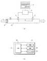
液体が通液される流路である配管10には、配管10内を流れる液体の導電率を測定する第一の測定手段である導電率計1と第二の測定手段である導電率計2とが、液体の流れ方向において距離Lを隔てて設置されており、両導電率計1、2が設けられている箇所の配管の断面積Dは等しくなっている。なお、配管10は、図では直管で示されているが、本発明としては、配管は直管だけでなく、曲がったものや薄く平たい形状のものであってもよく、要は液体が通液される流路を形成するものであればよい。
なお、導電率計1の上流側では、配管10内に系外から他の液体や物質の投入が可能なサンプル穴11が設けられている。Hereinafter, an embodiment of the present invention will be described.
In the
On the upstream side of the conductivity meter 1, a sample hole 11 is provided in the
前記導電率計1と導電率計2とは、制御装置3に接続されており、該制御装置3からの電圧印加によって各導電率計1、2から導電率の測定結果が制御装置3に出力可能になっている。制御装置3には、図1(b)に詳細に示すように、CPU30とこれを動作させるプログラムを格納したROM31と、ワークエリアとなるRAM32と、導電率1、2間の通液距離L、導電率計1、2が設けられている箇所での配管10の断面積Dなどを不揮発に記憶したフラッシュメモリ33と備えている。また、制御装置3には、CRTやLCDなどからなる表示部4が接続されており、測定波形や算出結果の表示が可能になっている。上記導電率計1、2および制御装置3、表示部部4によって液体流計測システムが構成されている。 The conductivity meter 1 and the
次に、上記液体流計測システムを用いた液体流計測方法について説明する。
配管10では、水などの液体が通液されており、所定の速度vで配管10内を移動する。
一方、制御装置3では、測定の開始に伴って導電率計1、2に電圧の印加や電流の通電を連続して行う。これらの電圧印加などはパルス状に行うのが望ましい。導電率計1、2では、制御装置3からの電圧印加などによって上記液体の導電率が測定され、測定結果が制御装置3に送信される。制御装置3では、前記導電率計1、2からの測定結果を経時変化として受信する。この測定結果の経時変化は、波形として表示部4に表示することができる。この実施形態の液体流計測システムでは、後述するように波形を分析して液体の流速、流量の算出が可能になっているが、本発明としては、上記波形表示などを利用して、操作者がそれぞれの測定結果の経時変化間の時間差を把握して液体の流速等を算出することも可能である。Next, a liquid flow measurement method using the liquid flow measurement system will be described.
A liquid such as water is passed through the
On the other hand, the
この実施形態では、ROM31に格納されたプログラムによって動作するCPU30によって上記測定結果の経時変化を波形分析をして比較し、経時変化間での時間差tを求める。波形分析は、前述したように、波形の周期や立ち上がり時間、立ち下がり時間、振幅、ピーク位置などによって行うことができ、既知の方法を採用することができる。
図2は、上記測定波形の経時変化の一例を示すものであり、導電率計1で測定された波形に対し、導電率計2で測定された波形が時間的に遅れた(位相差を有する)ものとして現れている。その遅れを時間差tとして取得する。また、導電率計1、2間の通液距離Lは、導電率計1、2を配管10に設置する際に把握されており、該データはフラッシュメモリ33に記憶しておく。CPU30では、流速の算出において、通液距離データをフラッシュメモリ33より読み出し、下記式1に示すように上記で得られた時間差tで除することで流速vを算出する。例えば、図2に示されるように時間差tが2分であり、導電率計1、2間の通液距離Lが10mであるとすると、流速vは、5m/min.と算出される。すなわち、制御装置3は、本発明の流速算出手段として機能をする。In this embodiment, the
FIG. 2 shows an example of the change over time of the measured waveform. The waveform measured by the
v=L/t …式1 v = L / t Equation 1
以上のように、導電率計の位置は一定であるため、上記位相差は液体の流速によってのみ変動することとなるため、導電率計1、22が出力する導電率の位相差を計測することで、液体の流速を容易かつ安定して計測することが可能となる。液体に導電率の変動が起こらない場合には、たとえば導電率計1の上流側に設けたサンプル孔11から水道水や純水を注入して導電率の変動を外部から発生させることで、高い測定精度を得ることができる。
なお、配管は、上記のように直管だけでなく、曲がったものや薄く平たい形状の、従来の流量計では組込が難しいものに対しても適用可能であり、また導電率計の電極が設置できればどこでも流速を計測できることとなるため、設置工事が容易な流量計を実現することが可能となる。As described above, since the position of the conductivity meter is constant, the phase difference fluctuates only depending on the flow velocity of the liquid. Therefore, the phase difference of the conductivity output by the
Piping can be applied not only to straight pipes as described above, but also to bent and thin flat shapes that are difficult to incorporate with conventional flowmeters, and the electrodes of the conductivity meter Since the flow velocity can be measured anywhere as long as it can be installed, it is possible to realize a flow meter that is easy to install.
次に、上記液体の流量を算出する場合について説明をすると、上記で求めた時間差tと、通液距離Lと、配管10の断面積Dを用いて算出する、断面積Dは、フラッシュメモリ33に記憶されているデータをCPU30によって読み出し、該CPU30によって、下記式2に基づいて流量Mを算出する。したがって、制御装置3は、流量算出手段として機能する。 Next, the case of calculating the flow rate of the liquid will be described. The cross-sectional area D calculated using the time difference t obtained above, the liquid passing distance L, and the cross-sectional area D of the
M=L/t×D …式2 M = L / t ×
なお、この実施形態では、流速と流量のいずれも算出可能なものとして説明をしたが、本発明としては。いずれ一方のみが算出可能となっているものであってもよい。 In this embodiment, description has been made assuming that both the flow velocity and the flow rate can be calculated, but as the present invention. Only one of them may be calculated.
(実施形態2)
次に、上記液体流計測システムをろ過手段に適用した例を図3に基づいて説明する。
供給側配管13は、それぞれが同じ断面積となるように透過側配管14と濃縮側配管15とに分岐しており、供給側配管13と透過側配管14との間にフィルタ12が配置されている。
供給側配管13には、前記実施形態と同様に配管内を通液する液体の導電率を測定する導電率計1が設けられ、透過側配管14に配管内を通液する液体の導電率を測定する導電率計2が設けられている。導電率計1と導電率計2とは通液距離L0によって離れている。導電率計1、2は、前記実施形態と同様に制御装置(図示しない)に接続されている。
このろ過手段では、供給側配管13を通液される液体にろ過すべき成分が含まれており、該成分はフィルタ12を通過することなく濃縮側配管15に濃縮されて通液され、ろ過された液体は透過側配管14に通液される。(Embodiment 2)
Next, the example which applied the said liquid flow measurement system to the filtration means is demonstrated based on FIG.
The
The
In this filtering means, the component to be filtered is contained in the liquid passed through the
上記導電率計1、2では、前記実施形態と同様に液体の導電率が測定され、制御装置で分析がされ、経時変化の時間差(位相差)t0が求められる。この時間差t0で前記通液距離L0を除することで用いて前記と同様に透過側配管14における流速v0を算出(V0=L0/t0)することができる。したがって、制御装置は透過流束算出手段として機能する。In the
上記実施形態では、導電率計2を透過側配管14に設けたが、濃縮側配管15に設けて濃縮側の流速や流量を算出することも可能である。
また、透過側と濃縮側の一方に測定手段としての伝導率計を設置した場合、透過側と濃縮側のうちの他方の配管に異常検知測定手段としての導電率計を設置することができる。該異常検知用の導電率計においても導電率計1との間の通液距離に従って、導電率計1で得られる測定結果に対し所定の位相差を有する測定結果が得られる。上記導電率計1、2と異常検知用導電率計での測定結果の相関関係を比較することで、上記導電率計1、2のいずれかで、導電率計間で単なる位相差と異なる相違を示す場合には、当該導電率計に異常が生じているという判定を行うことができる。上記制御装置は、測定手段異常判定手段としての機能を有している。
すなわち、前記透過側の流路または前記濃縮側の流路のうち、前記第二の測定手段が設置される流路と異なる他方の流路に設置されて前記液体の状態を測定する異常検知測定手段を備え、前記前記第一の測定手段で測定された前記液体の状態の経時変化と第二の測定手段で測定された前記液体の状態の経時変化と前記異常検知測定手段で測定された前記液体の状態の経時変化との比較によって前記第一の測定手段または第二の測定手段の異常を判定する測定手段異常判定手段を備えることができる。In the above embodiment, the
In addition, when a conductivity meter as a measuring unit is installed on one of the transmission side and the concentration side, a conductivity meter as an abnormality detection measuring unit can be installed on the other pipe on the transmission side and the concentration side. Also in the conductivity meter for detecting an abnormality, a measurement result having a predetermined phase difference with respect to the measurement result obtained by the conductivity meter 1 is obtained according to the liquid passing distance from the conductivity meter 1. By comparing the correlation between the measurement results of the
That is, the abnormality detection measurement that is installed in the other flow path different from the flow path in which the second measurement means is installed, of the permeation side flow path or the concentration side flow path, and measures the state of the liquid And the time-dependent change of the liquid state measured by the first measuring means, the time-dependent change of the liquid state measured by the second measuring means, and the abnormality detection measuring means A measuring means abnormality determining means for determining an abnormality of the first measuring means or the second measuring means by comparison with a change with time of the liquid state can be provided.
(実施形態3)
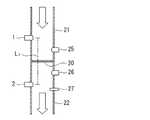
次に、上記液体流計測システムを膜ろ過装置に適用した例を図4に基づいて説明する。
同じ断面積を有する供給側配管21と透過側配管22との間にろ過膜20が配置されており、供給側配管21に、前記実施形態と同様に配管内を通液する液体の導電率を測定する導電率計1が設けられ、透過側配管21に配管内を通液する液体の導電率を測定する導電率計2が設けられている。導電率計1と導電率計2とは通液距離L1によって離れている。導電率計1、2は、前記実施形態と同様に制御装置(図示しない)に接続されている。また、供給側配管21には、通液する液体の圧力を測定する圧力計25が配置され、透過側配管22には、通液する液体の圧力および温度を測定する圧力計26および温度計27が配置されている。これらの測定結果は、前記した制御装置に送信される。
この膜ろ過装置では、供給側配管21を通液される液体にろ過すべき成分が含まれており、該成分はろ過膜20を通過することなくろ過膜20に補足され、ろ過された液体は透過側配管22に通液される。(Embodiment 3)
Next, the example which applied the said liquid flow measurement system to the membrane filtration apparatus is demonstrated based on FIG.
The
In this membrane filtration device, the component to be filtered is contained in the liquid passed through the
上記導電率計1、2では、前記実施形態と同様に液体の導電率が測定され、制御装置で分析がされ、経時変化の時間差(位相差)が求められる。この時間差で導電率計1、2間の通液距離を除することで前記と同様に透過側配管18における流速を算出することができる。また、上記圧力計25、26で測定された圧力の差(差圧ΔP)と、温度計27で測定された温度Tを用いて、以下の式によって膜流速を算出することができる。すなわち、制御装置は、膜流束算出手段として機能する。
ユニットの透過流速
=単位膜面積当りの流量(m3/日)×基準膜面有効圧÷実機膜面有効圧×温度換算係数
=(S×L/dT×(1−Km)/Sm)×(Pstd/dP)×Kt …式3
ここで
S :配管の断面積(m2)
L :導電率計1と2の流路(m)
dT:導電率計1と2の時間差
Km:膜の容積率
Sm:膜の有効面積(m2)
Pstd:膜の基準膜面有効圧(定数)
dP:実記膜面有効圧力=圧力計25の値−圧力計26の値
Kt:温度換算係数=温度計27の値によって定まる膜の固値In the
Permeation flow rate of unit = Flow rate per unit membrane area (m3 / day) × Reference membrane surface effective pressure ÷ Actual membrane surface effective pressure × Temperature conversion factor = (S × L / dT × (1-Km) / Sm) × (Pstd / dP) ×
Where S: sectional area of the pipe (m2 )
L: Flow path of conductivity meters 1 and 2 (m)
dT: Time difference between
Pstd: Reference film surface effective pressure (constant) of the film
dP: actual film effective pressure = value of
以上、本発明について上記実施形態に基づいて説明を行ったが、本発明は、上記実施形態の説明の内容に限定をされるものではなく、本発明の範囲を逸脱しない限りは当然に適宜の変更が可能である。 Although the present invention has been described based on the above embodiment, the present invention is not limited to the contents of the description of the above embodiment, and is naturally appropriate as long as it does not depart from the scope of the present invention. It can be changed.
1 導電率計
2 導電率計
3 制御装置
4 表示部
12 フィルタ
13 供給側配管
14 透過側配管
15 濃縮側配管
20 ろ過膜
21 供給側配管
22 透過側配管
25 圧力計
26 圧力計
27 温度計
30 CPU
31 ROM
32 RAM
33 フラッシュメモリDESCRIPTION OF SYMBOLS 1
31 ROM
32 RAM
33 Flash memory
Claims (12)
Translated fromJapanese前記液体の流れ方向において異なる箇所で前記流路に設置されて前記液体の状態を測定する第一の測定手段および第二の測定手段と、前記第一の測定手段で測定された前記液体の状態の経時変化と第二の測定手段で測定された前記液体の状態の経時変化との比較によって前記経時変化間の時間差を計測する時間差計測手段と、該時間差計測手段で計測された前記時間差と前記第一の測定手段の設置位置と前記第二の測定手段との設置位置間の通液距離とに基づいて前記流路を流れる前記液体の流速を算出する流速算出手段とを備えることを特徴とする液体流計測システム。A liquid flow measurement system installed in a flow path through which liquid flows,
A first measuring means and a second measuring means installed in the flow path at different locations in the liquid flow direction to measure the state of the liquid, and the state of the liquid measured by the first measuring means; A time difference measuring means for measuring a time difference between the time-dependent changes by comparing the time-dependent change of the liquid and the time-dependent change of the liquid state measured by the second measuring means, and the time difference measured by the time difference measuring means and the time difference A flow rate calculating means for calculating a flow rate of the liquid flowing in the flow path based on a liquid passing distance between the installation positions of the first measurement means and the second measurement means; Liquid flow measurement system.
前記液体の流れ方向において異なる箇所で前記流路に設置されて前記液体の状態を測定する第一の測定手段および第二の測定手段と、前記第一の測定手段で測定された前記液体の状態の経時変化と第二の測定手段で測定された前記液体の状態の経時変化との比較によって前記経時変化間の時間差を計測する時間差計測手段と、該時間差計測手段で計測された前記時間差と前記第一の測定手段の設置位置と前記第二の測定手段との設置位置間の通液距離と流路の断面積とに基づいて前記流路を流れる前記液体の流量を算出する流量算出手段とを備えることを特徴とする液体流計測システム。A liquid flow measurement system installed in a flow path through which liquid flows,
A first measuring means and a second measuring means installed in the flow path at different locations in the liquid flow direction to measure the state of the liquid, and the state of the liquid measured by the first measuring means; A time difference measuring means for measuring a time difference between the time-dependent changes by comparing the time-dependent change of the liquid and the time-dependent change of the liquid state measured by the second measuring means, and the time difference measured by the time difference measuring means and the time difference A flow rate calculation means for calculating a flow rate of the liquid flowing through the flow path based on a liquid passing distance between the installation position of the first measurement means and the installation position of the second measurement means and a cross-sectional area of the flow path; A liquid flow measurement system comprising:
前記供給側の流路に設置されて前記液体の状態を測定する第一の測定手段と、前記透過側の流路または前記濃縮側の流路に設置されて前記液体の状態を測定する第二の測定手段と、前記第一の測定手段で測定された前記液体の状態の経時変化と第二の測定手段で測定された前記液体の状態の経時変化との比較によって前記経時変化間の時間差を計測する時間差計測手段と、該時間差計測手段で計測された前記時間差と前記第一の測定手段の設置位置と前記第二の測定手段との設置位置間の通液距離とに基づいて前記ろ過手段内を流れる前記液体の流速を算出する流速算出手段とを備えることを特徴とする液体流計測システム。A liquid flow measurement system installed in a filtration system comprising filtration means for passing a liquid, and flow paths connected to the supply side, the permeation side, and the concentration side of the filtration means,
A first measuring unit installed in the supply-side channel and measuring the state of the liquid; and a second measuring unit installed in the permeation-side channel or the concentration-side channel and measuring the state of the liquid. A time difference between the time changes by comparing the time change of the liquid state measured by the first measurement means and the time change of the liquid state measured by the second measurement means. The filtering means based on the time difference measuring means to measure, the time difference measured by the time difference measuring means, and the liquid passing distance between the installation position of the first measurement means and the installation position of the second measurement means A liquid flow measurement system comprising: a flow velocity calculation means for calculating a flow velocity of the liquid flowing inside.
前記供給側の流路に設置されて前記液体の状態を測定する第一の測定手段と、前記透過側の流路または前記濃縮側の流路に設置されて前記液体の状態を測定する第二の測定手段と、前記第一の測定手段で測定された前記液体の状態の経時変化と第二の測定手段で測定された前記液体の状態の経時変化との比較によって前記経時変化間の時間差を計測する時間差計測手段と、該時間差計測手段で計測された前記時間差と前記第一の測定手段の設置位置と前記第二の測定手段との設置位置間の通液距離と前記ろ過手段の内径断面積とに基づいて前記ろ過手段の透過流束を算出する透過流束算出手段とを備えることを特徴とする液体流計測システム。A liquid flow measurement system installed in a filtration system comprising filtration means for passing a liquid, and flow paths connected to the supply side, the permeation side, and the concentration side of the filtration means,
A first measuring unit installed in the supply-side channel and measuring the state of the liquid; and a second measuring unit installed in the permeation-side channel or the concentration-side channel and measuring the state of the liquid. A time difference between the time changes by comparing the time change of the liquid state measured by the first measurement means and the time change of the liquid state measured by the second measurement means. A time difference measuring means for measuring, the time difference measured by the time difference measuring means, a liquid passing distance between the installation position of the first measurement means and the installation position of the second measurement means, and the inner diameter breakage of the filtration means A liquid flow measurement system comprising: a permeation flux calculating means for calculating a permeation flux of the filtering means based on the area.
Priority Applications (1)
| Application Number | Priority Date | Filing Date | Title |
|---|---|---|---|
| JP2007312278AJP2009139091A (en) | 2007-12-03 | 2007-12-03 | Liquid flow measurement method and liquid flow measurement system |
Applications Claiming Priority (1)
| Application Number | Priority Date | Filing Date | Title |
|---|---|---|---|
| JP2007312278AJP2009139091A (en) | 2007-12-03 | 2007-12-03 | Liquid flow measurement method and liquid flow measurement system |
Publications (1)
| Publication Number | Publication Date |
|---|---|
| JP2009139091Atrue JP2009139091A (en) | 2009-06-25 |
Family
ID=40869860
Family Applications (1)
| Application Number | Title | Priority Date | Filing Date |
|---|---|---|---|
| JP2007312278APendingJP2009139091A (en) | 2007-12-03 | 2007-12-03 | Liquid flow measurement method and liquid flow measurement system |
Country Status (1)
| Country | Link |
|---|---|
| JP (1) | JP2009139091A (en) |
Cited By (5)
| Publication number | Priority date | Publication date | Assignee | Title |
|---|---|---|---|---|
| JP2015517834A (en)* | 2012-03-23 | 2015-06-25 | ネクステージ メディカル インコーポレイテッド | Peritoneal dialysis system, device and method |
| US9861733B2 (en) | 2012-03-23 | 2018-01-09 | Nxstage Medical Inc. | Peritoneal dialysis systems, devices, and methods |
| US9907897B2 (en) | 2011-03-23 | 2018-03-06 | Nxstage Medical, Inc. | Peritoneal dialysis systems, devices, and methods |
| US11207454B2 (en) | 2018-02-28 | 2021-12-28 | Nxstage Medical, Inc. | Fluid preparation and treatment devices methods and systems |
| US12048791B2 (en) | 2017-06-24 | 2024-07-30 | Nxstage Medical, Inc. | Peritoneal dialysis fluid preparation and/or treatment devices methods and systems |
- 2007
- 2007-12-03JPJP2007312278Apatent/JP2009139091A/enactivePending
Cited By (23)
| Publication number | Priority date | Publication date | Assignee | Title |
|---|---|---|---|---|
| US10898630B2 (en) | 2011-03-23 | 2021-01-26 | Nxstage Medical, Inc. | Peritoneal dialysis systems, devices, and methods |
| US10688234B2 (en) | 2011-03-23 | 2020-06-23 | Nxstage Medical, Inc. | Peritoneal dialysis systems, devices, and methods |
| US12246121B2 (en) | 2011-03-23 | 2025-03-11 | Nxstage Medical, Inc. | Peritoneal dialysis systems, devices, and methods |
| US9907897B2 (en) | 2011-03-23 | 2018-03-06 | Nxstage Medical, Inc. | Peritoneal dialysis systems, devices, and methods |
| US10046100B2 (en) | 2011-03-23 | 2018-08-14 | Nxstage Medical, Inc. | Peritoneal dialysis systems, devices, and methods |
| JP2018134444A (en)* | 2011-03-23 | 2018-08-30 | ネクステージ メディカル インコーポレイテッド | Peritoneal dialysis circulation system |
| US10603424B2 (en) | 2011-03-23 | 2020-03-31 | Nxstage Medical, Inc. | Peritoneal dialysis systems, devices, and methods |
| US11717601B2 (en) | 2011-03-23 | 2023-08-08 | Nxstage Medical, Inc. | Dialysis systems, devices, and methods |
| US11135348B2 (en) | 2011-03-23 | 2021-10-05 | Nxstage Medical, Inc. | Peritoneal dialysis systems, devices, and methods |
| US10688235B2 (en) | 2011-03-23 | 2020-06-23 | Nxstage Medical, Inc. | Peritoneal dialysis systems, devices, and methods |
| US11690941B2 (en) | 2011-03-23 | 2023-07-04 | Nxstage Medical, Inc. | Peritoneal dialysis systems, devices, and methods |
| US11433169B2 (en) | 2011-03-23 | 2022-09-06 | Nxstage Medical, Inc. | Dialysis systems, devices, and methods |
| US10610630B2 (en) | 2011-03-23 | 2020-04-07 | Nxstage Medical, Inc. | Peritoneal dialysis systems, devices, and methods |
| US11224684B2 (en) | 2011-03-23 | 2022-01-18 | Nxstage Medical, Inc. | Peritoneal dialysis systems, devices, and methods |
| US11433170B2 (en) | 2011-03-23 | 2022-09-06 | Nxstage Medical, Inc. | Dialysis systems, devices, and methods |
| JP2015517834A (en)* | 2012-03-23 | 2015-06-25 | ネクステージ メディカル インコーポレイテッド | Peritoneal dialysis system, device and method |
| EP3222305A1 (en)* | 2012-03-23 | 2017-09-27 | NxStage Medical, Inc. | Peritoneal dialysis systems and devices |
| US9861733B2 (en) | 2012-03-23 | 2018-01-09 | Nxstage Medical Inc. | Peritoneal dialysis systems, devices, and methods |
| US12048791B2 (en) | 2017-06-24 | 2024-07-30 | Nxstage Medical, Inc. | Peritoneal dialysis fluid preparation and/or treatment devices methods and systems |
| US11364328B2 (en) | 2018-02-28 | 2022-06-21 | Nxstage Medical, Inc. | Fluid preparation and treatment devices methods and systems |
| US11207454B2 (en) | 2018-02-28 | 2021-12-28 | Nxstage Medical, Inc. | Fluid preparation and treatment devices methods and systems |
| US11872337B2 (en) | 2018-02-28 | 2024-01-16 | Nxstage Medical, Inc. | Fluid preparation and treatment devices methods and systems |
| US12409259B2 (en) | 2018-02-28 | 2025-09-09 | Nxstage Medical, Inc. | Fluid preparation and treatment devices methods and systems |
Similar Documents
| Publication | Publication Date | Title |
|---|---|---|
| EP2535688B1 (en) | Method for generating a diagnostic from a deviation of a flow meter parameter | |
| JP6300924B2 (en) | Coriolis type device for directly measuring the source and method for measuring the source directly | |
| CA2833329C (en) | Nuclear magnetic flow meter and method for operation of nuclear magnetic flow meters | |
| EP2806254B1 (en) | Fuel consumption measuring instrument | |
| EP2028457A1 (en) | Multi-vortex flowmeter integrating pressure gauge | |
| US11255766B2 (en) | Vibronic sensor and measuring assembly for monitoring a flowable medium | |
| JP2009139091A (en) | Liquid flow measurement method and liquid flow measurement system | |
| US20170343457A1 (en) | Measuring arrangement and method for measuring the density of flowable media | |
| CN110987097B (en) | Method for measuring gas-liquid multiphase flow by using pressure fluctuation | |
| CN101539016B (en) | A method and device for measuring the flow rate of gas-liquid multiphase flow by using thermal diffusion | |
| JP6419296B2 (en) | Coriolis type device for directly measuring the source and method for measuring the source directly | |
| NO20171056A1 (en) | Ultrasonic viscometer | |
| NZ630410A (en) | Apparatus and method for determining a non-condensable gas parameter | |
| US20130219986A1 (en) | Method and apparatus for calibrating a flow meter | |
| US20180246024A1 (en) | Method and measuring apparatus for determining compressibility of a flowing fluid | |
| US20170241966A1 (en) | Method and system for determining the fractions of a streaming gaseous medium | |
| US4036722A (en) | Flow through cell assembly | |
| Hepp et al. | Multi-parameter monitoring of binary gas mixtures: Concentration and flow rate by DC excitation of thermal sensor arrays | |
| Salehi et al. | Wet Gas Flow Measurement Using a Coriolis Meter: Influences of Flow Conditions | |
| RU2303768C1 (en) | Flow meter | |
| CN204346550U (en) | Fine liquid flow metering pick-up unit | |
| CN201221965Y (en) | Container for real-time detecting liquid quality | |
| RU35009U1 (en) | INSTALLATION FOR MEASURING THE FLOW OF A GAS-LIQUID FLUID | |
| Hewes | Development of an interference probe for the simultaneous measurement of turbulent concentration and velocity fields | |
| TWM669064U (en) | Differential Pressure Flow Meter for Mixed Fluids |