JP2009136250A - Biological sample reaction chip, biological sample reaction device, and biological sample reaction method - Google Patents
Biological sample reaction chip, biological sample reaction device, and biological sample reaction methodDownload PDFInfo
- Publication number
- JP2009136250A JP2009136250AJP2007318627AJP2007318627AJP2009136250AJP 2009136250 AJP2009136250 AJP 2009136250AJP 2007318627 AJP2007318627 AJP 2007318627AJP 2007318627 AJP2007318627 AJP 2007318627AJP 2009136250 AJP2009136250 AJP 2009136250A
- Authority
- JP
- Japan
- Prior art keywords
- reaction
- biological sample
- well
- sample reaction
- chip
- Prior art date
- Legal status (The legal status is an assumption and is not a legal conclusion. Google has not performed a legal analysis and makes no representation as to the accuracy of the status listed.)
- Granted
Links
Images


Landscapes
- Measuring Or Testing Involving Enzymes Or Micro-Organisms (AREA)
- Automatic Analysis And Handling Materials Therefor (AREA)
- Apparatus Associated With Microorganisms And Enzymes (AREA)
Abstract
Translated fromJapaneseDescription
Translated fromJapanese本発明は、核酸増幅などの生体試料反応を行うための、生体試料反応用チップ、生体試料反応装置、および生体試料反応方法に関するものである。 The present invention relates to a biological sample reaction chip, a biological sample reaction device, and a biological sample reaction method for performing a biological sample reaction such as nucleic acid amplification.
近年、僅かなDNAを短時間で増幅するPCR法が、医療や食品の分析、犯罪捜査や生物学の研究等で盛んに用いられるようになった。取り扱いが容易な卓上型のPCR検査装置も開発され、手軽にPCR法が行えるようになった。しかしながら、これらのPCR装置はPCR反応に必要な熱サイクルを実現するために、異なる温度に設定された複数のインキュベータを用意し、それらのインキュベータ間でPCR溶液の入ったチューブを移動させていた。チューブの移動機構は複雑であり、また、この方法では温度変化が急峻になるが、反応を行う上ではより緩やかな温度勾配が望ましい。また、1つのサーマルブロックを用いて、加熱冷却を繰り返す方法もあったが、温度変化に時間を要し、反応時間や消費電力の点から改善が望まれていた。 In recent years, the PCR method for amplifying a small amount of DNA in a short time has come to be actively used in medical and food analysis, criminal investigation, biological research and the like. An easy-to-handle desktop PCR testing device has also been developed, making it easy to perform PCR. However, in order to realize the thermal cycle necessary for the PCR reaction, these PCR apparatuses prepare a plurality of incubators set at different temperatures, and move the tubes containing the PCR solutions between the incubators. The moving mechanism of the tube is complicated, and the temperature change becomes steep in this method, but a gentler temperature gradient is desirable for the reaction. There was also a method of repeating heating and cooling using one thermal block, but it took time to change the temperature, and improvements were desired in terms of reaction time and power consumption.
この様な問題を解決する為、特許文献1には、DNAポリメラーゼ、鋳型DNA、プライマーDNA、及びdNTPを含む反応液を移動相として、外部に約94℃、約55℃、及び約73℃に調節された3種の加熱部が設けられた反応管内を移動させることにより、PCR反応を行う装置が開示されている。
しかし、特許文献1に記載された従来の装置は、1つの反応管を用いて複数の試料の反応を行おうとすると、試料の混入が生じる恐れがあった。PCR反応は僅かな試料を極度に増幅する手法であり、異なる試料の混入は避ける必要がある。複数の反応管を用いると試料の混入は避けられるが、送液ポンプが各々の反応管について必要となり装置が複雑化してしまう。 However, the conventional apparatus described in
そこで、本発明の目的は、微量な反応液で効率よく反応処理を行うことが可能で、簡易な方法で温度制御ができ、消費電力も低減可能な生体試料反応用チップ、生体試料反応装置、および生体試料反応方法を得ることである。 Therefore, an object of the present invention is to perform a reaction process efficiently with a very small amount of a reaction solution, perform temperature control by a simple method, and reduce power consumption, a biological sample reaction chip, a biological sample reaction device, And obtaining a biological sample reaction method.
本発明に係る生体試料反応用チップは、第1〜第3の反応部と、前記第1の反応部と前記第2の反応部を繋ぐ第1の流路と、前記第2の反応部と前記第3の反応部を繋ぐ第2の流路と、を備え、前記第1の流路と前記第1の反応部の成す角度をA、前記第1の流路と前記第2の反応部の成す角度をB、前記第1の流路と前記第2の流路の成す角度をCとすると、A<C、かつ、0度<B<180度、かつ、C>90度、であることを特徴とする。 The biological sample reaction chip according to the present invention includes first to third reaction units, a first flow path connecting the first reaction unit and the second reaction unit, and the second reaction unit. A second flow path connecting the third reaction section, and the angle formed by the first flow path and the first reaction section is A, the first flow path and the second reaction section. A <C, 0 <B <180 degrees, and C> 90 degrees, where B is the angle formed by C and the angle formed by the first flow path and the second flow path is C. It is characterized by that.
また、本発明に係る生体試料反応装置は、上記の生体試料反応用チップを用いて生体試料反応処理を行うための生体試料反応装置であって、水平方向の回転軸の周りに回転可能であり、前記生体試料反応用チップを収納可能な収容部と、回転軸近傍に設けられた温度調節手段を備え、前記回転軸に対して対称な温度分布を有するものである。 A biological sample reaction device according to the present invention is a biological sample reaction device for performing biological sample reaction processing using the biological sample reaction chip described above, and is rotatable around a horizontal rotation axis. And an accommodating portion capable of accommodating the biological sample reaction chip and a temperature adjusting means provided in the vicinity of the rotation axis, and having a temperature distribution symmetrical to the rotation axis.
本発明に係る生体試料反応用チップは、本発明に係る生体試料反応装置を用いて生体試料反応処理を行うのに適している。
また、前記第1〜第3の反応部と前記第1および第2の流路に反応液と混和せず前記反応液よりも比重の軽い液体が充填されており、前記液体中に反応液が液滴の状態で含まれることが望ましい。これにより、微量な反応液で効率よく反応を行うことができる。例えば、液体がミネラルオイルの場合には、反応液はミネラルオイル中に非乳化状態の液滴として含まれている。The biological sample reaction chip according to the present invention is suitable for performing biological sample reaction processing using the biological sample reaction device according to the present invention.
Also, the first to third reaction parts and the first and second flow paths are filled with a liquid that is immiscible with the reaction liquid and has a specific gravity lower than that of the reaction liquid, and the reaction liquid is contained in the liquid. It is desirable to be contained in the state of a droplet. Thereby, it can react efficiently with a trace amount reaction liquid. For example, when the liquid is mineral oil, the reaction liquid is contained in the mineral oil as non-emulsified droplets.
また、本発明に係る生体試料反応装置は、回転軸に対して対称な温度分布が形成されるので、装置を回転させることにより、温度制御が簡単で消費電力も低い熱サイクル反応を実施することができる。 In addition, since the biological sample reaction apparatus according to the present invention forms a symmetric temperature distribution with respect to the rotation axis, the thermal cycle reaction with simple temperature control and low power consumption can be performed by rotating the apparatus. Can do.
また、前記収容部は、前記第1の反応部、前記第2の反応部、前記第3の反応部の順に前記回転軸から遠くに配置されるように、前記生体試料反応用チップを収納可能なことが望ましい。これにより、反応液を第1の反応部、第2の反応部、および第3の反応部の間で移動させることにより、3つの異なる温度状態での熱サイクル反応を実現することができる。 The accommodating portion can accommodate the biological sample reaction chip so that the first reaction portion, the second reaction portion, and the third reaction portion are arranged away from the rotation shaft in this order. It is desirable. Thereby, the thermal cycle reaction in three different temperature states is realizable by moving a reaction liquid between a 1st reaction part, a 2nd reaction part, and a 3rd reaction part.
本発明に係る生体試料反応方法は、上記の生体試料反応装置を用いた生体試料反応方法であって、前記生体試料反応装置を前記回転軸の周りに回転させることにより、前記反応液の液滴を前記第1〜第3の反応部の間で移動させ、各々の反応部で生体試料反応処理を行うものである。
本発明によれば、回転軸に対して対称な温度分布が形成されるので、反応液を第1の反応部、第2の反応部、および第3の反応部の間で移動させることにより、温度制御が簡単で消費電力も低い、熱サイクル反応を実現することができる。The biological sample reaction method according to the present invention is a biological sample reaction method using the biological sample reaction device described above, and the droplet of the reaction liquid is obtained by rotating the biological sample reaction device around the rotation axis. Is moved between the first to third reaction units, and a biological sample reaction process is performed in each reaction unit.
According to the present invention, a symmetrical temperature distribution is formed with respect to the rotation axis, and therefore, by moving the reaction liquid between the first reaction unit, the second reaction unit, and the third reaction unit, It is possible to realize a heat cycle reaction that is simple in temperature control and low in power consumption.
また、前記生体試料反応処理は核酸増幅を含む処理であり、前記反応液には、ターゲット核酸、プライマー、核酸を増幅するための酵素、及びヌクレオチドが所定の濃度で含まれているようにすることができる。 The biological sample reaction treatment is a treatment including nucleic acid amplification, and the reaction solution contains a target nucleic acid, a primer, an enzyme for amplifying the nucleic acid, and nucleotides at a predetermined concentration. Can do.
以下、本発明の実施の形態について図面を参照して説明する。
実施の形態1.
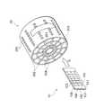
図1は、本発明の実施の形態1によるPCR用チップ(生体試料反応用チップ)10と、PCR反応装置(生体試料反応装置)20の構成を示す斜視図である。図に示すように、PCR用チップ10は、透明基板101,102を貼り合わせて構成されており、第1のウェル(第1の反応部)103、第2のウェル(第2の反応部)104、第3のウェル(第3の反応部)105、第1の流路106、第2の流路107が形成されている。透明基板101,102は例えばガラス基板とすることができる。各々1つの第1のウェル103、第2のウェル104、第3のウェル105、第1の流路106、及び第2の流路107によって1つの反応系が形成される。本実施形態では、PCR用チップ10は1つの基板状に7個の反応系を有している。Hereinafter, embodiments of the present invention will be described with reference to the drawings.
FIG. 1 is a perspective view showing the configuration of a PCR chip (biological sample reaction chip) 10 and a PCR reaction apparatus (biological sample reaction apparatus) 20 according to
PCR反応装置20は、円筒形に形成されており、中心部に水平方向に伸びた回転軸201を有している。回転軸201はヒータ(温度調節手段)となっており、回転軸201の近傍から外側へ向かうにつれて低くなっていく温度勾配が形成されている。 The
PCR反応装置20は、PCR用チップ10を収納可能なスリット(収容部)202を複数有している。スリット202は、回転軸201に対して対称に放射状に配置されている。スリット202へは、PCR用チップ10を矢印Aで示すように、第1のウェル103が回転軸201に近くなるように収納することができる。このようにPCR用チップ10を収納することにより、第1のウェル103、第2のウェル104、第3のウェル105の順に回転軸201から遠くに配置されるように収納される。 The
さらに、PCR反応装置20は、円筒の外周面近傍に配置されたフィルムヒータ203および回転軸201とフィルムヒータ203の間に同心円状に配置された断熱材204を備えており、温度勾配を正確にコントロールできるようになっている。また、外周面には複数の測定用ポート205が設けられている。測定用ポート205は、スリット202にPCR用チップ10を収納した時に、各々のチップに形成された7個の反応系が配置される位置と対応しており、測定用ポート205を通して外側から反応系内を測定することができるようになっている。 Furthermore, the
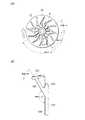
図2(A)は、PCR用チップ10の平面図である。図に示すように、第1のウェル103、第2のウェル104、第3のウェル105、第1の流路106、及び第2の流路107には、比重0.875のミネラルオイルが充填されている。第1の流路106、第2の流路107の幅は、第1のウェル103、第2のウェル104、及び第3のウェル105よりも若干狭く形成されている。これにより、ミネラルオイルの対流を制限する事ができ、第1のウェル103、第2のウェル104、及び第3のウェル105の間での温度勾配が明確に生じるようになっている。 FIG. 2A is a plan view of the
ミネラルオイル中には、反応液が非乳化状態の液滴として含まれている。反応液とミネラルオイルは混和せず、反応液の比重はミネラルオイルに比べて重いため、下方に沈降する。なお、反応液と混和せず、比重が反応液よりも軽いという条件を満たす液体であれば、ミネラルオイルの代わりに用いることができる。 In the mineral oil, the reaction liquid is contained as non-emulsified droplets. The reaction liquid and mineral oil are not mixed, and the specific gravity of the reaction liquid is heavier than that of mineral oil, so it settles downward. In addition, if it is a liquid which does not mix with a reaction liquid and satisfy | fills the conditions that specific gravity is lighter than a reaction liquid, it can be used instead of mineral oil.
図2(B)は、反応系の図2(A)のB−B断面を示す図である。図に示すように、第1のウェル103、第2のウェル104、及び第3のウェル105は、それぞれ第1の流路106に対して所定の角度を成すように形成されている。本実施形態では、第1のウェル103と第1の流路106の成す角度A=60度、第2のウェル104と第1の流路106の成す角度B=60度、第2の流路107と第1の流路106の成す角度C=180度に形成されている。 FIG. 2 (B) is a view showing a BB cross section of FIG. 2 (A) of the reaction system. As shown in the figure, the
次に、本実施形態によるPCR用チップ10およびPCR反応装置20を用いたPCR反応の実施方法について説明する。PCR用チップ10には、上述したように、ミネラルオイルと反応液が充填されている。ここでは、反応液には、ターゲット核酸、プライマー、ポリメラーゼ、及びヌクレオチド(dNTP)が反応に適した所定の濃度で含まれている。ターゲット核酸は、例えば血液、尿、唾液、髄液のような生体サンプルから抽出したDNA、または抽出したRNAから逆転写したcDNAなどを用いることができる。PCR用チップ10の各々の反応系には、異なるターゲット核酸及びプライマーの組み合わせからなる反応液を封入しておくことができる。 Next, a method for performing a PCR reaction using the
反応液を封入したPCR用チップ10を図1に示すようにPCR反応装置20のスリット202に収納する。
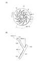
図3は、PCR用チップ10を収納したPCR反応装置20の、回転軸201に垂直な面の断面を示す模式図である。The
FIG. 3 is a schematic diagram showing a cross section of a surface perpendicular to the
ここでは、PCR反応装置20は、第1のウェル103が固定される回転軸201近傍の温度がPCR反応の熱変性温度(95℃)、第2のウェル104が固定される中間部の温度が伸長反応温度(72℃)、第3のウェル105が固定される外周部の温度がアニーリング温度(55℃)となるように、ヒーターによってコントロールされている。なお、温度の回転軸201に対する対称性を保持する点から、未使用のスリット202にもダミーのPCR用チップ10を挿入することが好ましい。 Here, in the
ここでは、PCR反応は熱変性(95℃)→アニーリング(55℃)→伸長反応(72℃)→熱変性(95℃)の熱サイクルを、各温度状態を等間隔で繰り返すことにより行う。
PCR反応装置20が図中の矢印方向(右回り)に回転することにより、PCR用チップ10は図中の領域(1)〜(3)(図中、丸数字で示す1〜3の領域)を繰り返し通過する。図中(1)の領域(図3の断面を時計の文字盤に見立てると1時〜5時に相当する領域)にPCR用チップ10がある期間は、反応液Pは第1のウェル103に位置する。このため、PCR用チップ10が領域(1)にある間は、95℃で熱変性処理が行われる。PCR用チップ10が領域(3)から領域(1)へ入る際、ミネラルオイル中の反応液はミネラルオイルより比重が重いため第2のウェル104から第1のウェル103へ沈降する。Here, the PCR reaction is performed by repeating a thermal cycle of thermal denaturation (95 ° C.) → annealing (55 ° C.) → extension reaction (72 ° C.) → thermal denaturation (95 ° C.) at equal intervals.
When the
次に、PCR用チップ10が領域(1)から領域(2)(5時〜9時に相当する領域)へ入ると、反応液は第1のウェル103から第3のウェル105へ移動する。このため、PCR用チップ10が領域(2)にある間は、55℃でアニーリング処理が行われる。領域(1)にある間は、第1のウェル103の壁と第1の流路106が60度の角度を成しているため、反応液は壁にかかって第1のウェル103に留まっているが、領域(2)に入ると、第1の流路106及び第2の流路107を通って第3のウェル105まで沈降する。 Next, when the
次に、PCR用チップ10が領域(2)から領域(3)(9時〜1時に相当する領域)へ入ると、反応液は第3のウェル105から第2のウェル104へ移動する。このため、PCR用チップ10が領域(3)にある間は、72℃で伸長反応処理が行われる。領域(2)にある間は、第3のウェル105が最も低い位置になるため、反応液は第3のウェル105に留まっている。領域(3)に入ると、第3のウェル105よりも第2のウェル104の方が低い位置になるので、反応液は第2のウェル104に移動する。第2のウェル104の壁と第1の流路106が60度の角度を成しているため、反応液は壁にかかって第2のウェル104に留まる。 Next, when the
さらに、PCR用チップ10が領域(3)から再び領域(1)へ入り、熱変性(95℃)→アニーリング(55℃)→伸長反応(72℃)→熱変性(95℃)の熱サイクルが繰り返される。領域(3)から領域(1)へ入ると、第2のウェル104の壁で保持されていた反応液が第1のウェル103まで移動する。 Furthermore, the
以上のように、本実施形態によれば、PCR反応装置20を回転させることにより、PCR反応の熱サイクルを繰り返すことができる。なお、図3に示すように、本実施形態では、領域(1)〜(3)はそれぞれ円全体の3分の1を占めているため、PCR用チップ10が各々の領域にある時間は等間隔となり、従って各温度状態を等間隔で繰り返すことができる。 As described above, according to the present embodiment, the
本実施形態によれば、PCR反応装置20が円筒状で、回転軸201部分にヒータが設けられているため、回転軸201の近傍から外側へ向かうにつれて低くなっていく温度勾配が形成されるので、温度分布が軸対称になるように制御しやすい。また、従来のように反応液の入ったチップを、複数のヒートブロック間で移動させたり、単一のヒートブロックの過熱冷却を繰り返して温度サイクルを実現する方式に比べ、温度制御が簡単で、消費電力も低減できる。また、ヒートブロック間でのチップの移動や、ヒートブロックの加熱冷却の必要がない分、短時間で反応を行うことができる。 According to this embodiment, since the
また、本実施形態によるPCR用チップ10は、ミネラルオイル中に反応液が非乳化状態の液滴として含まれるようにしたので、微量な反応液で効率よく反応を行うことができる。 In addition, since the
なお、PCR用チップ10に充填するミネラルオイルの粘度が高いほど、ミネラルオイル中での反応液の移動速度が遅くなるため、反応液がウェル間を移動する際の温度変化を緩やかにすることができる。 In addition, since the moving speed of the reaction solution in the mineral oil becomes slower as the viscosity of the mineral oil filled in the
また、本実施形態によるPCR用チップ10及びPCR反応装置20を用いてリアルタイムPCRを行う場合には、例えば、PCR反応装置20の最下点(6時に相当する位置)にCCDカメラ等を配置することにより、PCR用チップ10が6時の位置へきたときに、測定用ポート205を介して測定することができるので、サイクル毎の増幅産物量を測定することができる。 When performing real-time PCR using the
また本発明は、PCR反応以外にも、温度サイクルを繰り返して行う様々な反応に利用することができる。 Moreover, this invention can be utilized for various reaction performed by repeating a temperature cycle besides PCR reaction.
(変形例)
図4〜図9は、本実施形態の変形例を示す図である。図4(A)〜図9(A)は、PCR用チップ10を収納したPCR反応装置20の、回転軸201に垂直な面の断面を示す模式図、図4(B)〜図9(B)は、PCR用チップ10の反応系の断面(図2(A)のB−B断面)を示す図である。(Modification)
4-9 is a figure which shows the modification of this embodiment. FIGS. 4A to 9A are schematic views showing a cross section of a surface perpendicular to the
それぞれの変形例は、第1のウェル103と第1の流路106の成す角度A、第2のウェル104と第1の流路106の成す角度B、及び第2の流路107と第1の流路106の成す角度Cの組み合わせがそれぞれ異なっている。これらの角度を変えることにより、反応液が第1のウェル103、第2のウェル104、及び第3のウェル105にある期間を変化させることができる。PCR反応においては、熱変性(95℃)→アニーリング(55℃)→伸長反応(72℃)の時間比率は1通りではなく、以下の変形例はこのような場合に利用することができる。 Each modification includes an angle A formed by the
図4に示す例では、A=60度、B=30度、C=150度となっている。この場合、上記の実施形態と同様の仕組みにより、PCR用チップ10が2時〜5時に相当する位置にある間、反応液は第1のウェル103にあり、5時〜8時の位置では第3のウェル105に、8時〜2時の位置では第2のウェル104にある。よって、図4に示す例では、熱変性(95℃)→アニーリング(55℃)→伸長反応(72℃)の各温度状態を1:1:2の比率で繰り返す。 In the example shown in FIG. 4, A = 60 degrees, B = 30 degrees, and C = 150 degrees. In this case, the reaction solution is in the first well 103 while the
同様に、図5に示す例では、A=0度、B=30度、C=120度であり、PCR用チップ10が2時〜3時に相当する位置にある間、反応液は第1のウェル103にあり、3時〜7時の位置では第3のウェル105に、7時〜2時の位置では第2のウェル104にある。よって、図5に示す例では、熱変性(95℃)→アニーリング(55℃)→伸長反応(72℃)の各温度状態を1:4:7の比率で繰り返す。 Similarly, in the example shown in FIG. 5, A = 0 degrees, B = 30 degrees, and C = 120 degrees, and while the
図6に示す例では、A=30度、B=30度、C=120度であり、PCR用チップ10が2時〜4時に相当する位置にある間、反応液は第1のウェル103にあり、4時〜7時の位置では第3のウェル105に、7時〜2時の位置では第2のウェル104にある。よって、図6に示す例では、熱変性(95℃)→アニーリング(55℃)→伸長反応(72℃)の各温度状態を2:3:7の比率で繰り返す。 In the example shown in FIG. 6, A = 30 degrees, B = 30 degrees, and C = 120 degrees, and while the
図7に示す例では、A=90度、B=30度、C=120度であり、PCR用チップ10が2時〜6時に相当する位置にある間、反応液は第1のウェル103にあり、6時〜7時の位置では第3のウェル105に、7時〜2時の位置では第2のウェル104にある。よって、図7に示す例では、熱変性(95℃)→アニーリング(55℃)→伸長反応(72℃)の各温度状態を4:1:7の比率で繰り返す。 In the example shown in FIG. 7, A = 90 degrees, B = 30 degrees, and C = 120 degrees, and while the
図8に示す例では、A=90度、B=180度、C=120度であり、PCR用チップ10が9時〜6時に相当する位置にある間、反応液は第1のウェル103にあり、6時〜7時の位置では第3のウェル105に、7時〜9時の位置では第2のウェル104にある。よって、図7に示す例では、熱変性(95℃)→アニーリング(55℃)→伸長反応(72℃)の各温度状態を9:1:2の比率で繰り返す。 In the example shown in FIG. 8, A = 90 degrees, B = 180 degrees, and C = 120 degrees, and the reaction solution is placed in the first well 103 while the
図9に示す例では、A=120度、B=180度、C=150度であり、PCR用チップ10が9時〜7時に相当する位置にある間、反応液は第1のウェル103にあり、7時〜8時の位置では第3のウェル105に、8時〜9時の位置では第2のウェル104にある。よって、図7に示す例では、熱変性(95℃)→アニーリング(55℃)→伸長反応(72℃)の各温度状態を10:1:1の比率で繰り返す。 In the example shown in FIG. 9, A = 120 degrees, B = 180 degrees, and C = 150 degrees, and while the
なお、角度A,B,Cと各温度状態での反応時間の比率には、以下の関係がある。
熱変性(95℃):アニーリング(55℃):伸長反応(72℃)
=角度A+角度B:角度C−角度A:360度−(角度B+角度C)The angles A, B, and C and the reaction time ratio in each temperature state have the following relationship.
Thermal denaturation (95 ° C): Annealing (55 ° C): Elongation reaction (72 ° C)
= Angle A + Angle B: Angle C-Angle A: 360 degrees-(Angle B + Angle C)
角度A=0度の場合には、3時の位置を過ぎると反応液は第1のウェル103から第3のウェル105へ移動する。角度A≠0度の場合には、3時の位置から角度Aだけ回転するまで、第1のウェル103に留まる。また、3時の位置から角度C以上回転すると、第2のウェル104が第3のウェル105より下方に位置するようになるので、反応液は第2のウェル104へ移動する。また、3時の位置から角度Bだけ手前の位置まで、反応液は第2のウェル104に留まることができる。 In the case of the angle A = 0 degree, the reaction solution moves from the first well 103 to the third well 105 after the 3 o'clock position. If the angle A is not 0 °, it remains in the first well 103 until it is rotated by the angle A from the 3 o'clock position. If the
よって、3時の位置を0度とすると、角度Aから角度Cに至る区間では反応液は第2のウェル104に位置し、角度Cから(360度−角度B)の区間では第2のウェル104に位置し、(360度−角度B)から角度Aの区間では第1のウェル103に位置することになる。 Therefore, if the 3 o'clock position is 0 degree, the reaction solution is located in the second well 104 in the section from the angle A to the angle C, and the second well in the section from the angle C to (360 degrees−angle B). 104, and in the section from (360 degrees-angle B) to angle A, it is located in the
なお、角度A<角度Cである。これは、角度C≦角度Aであると、反応液が第1のウェル103から沈降した時点で第2のウェル104の方が第3のウェル105より下方になってしまうため、反応液が第3のウェル105に留まる時間がなくなるからである。 Note that angle A <angle C. This is because when the angle C ≦ angle A, the
また、0度<角度B<180度である。角度Bが小さいほど反応液が第2のウェル104に留まる時間が長くなり、180度を超えると第3のウェル105から第2のウェル104を通過して第1のウェル103まで沈降してしまう。 Further, 0 degree <angle B <180 degrees. The smaller the angle B, the longer the time for which the reaction solution stays in the
また、角度C>90度である。Cが90度以下の場合、第2のウェル104と第3のウェル105の回転軸201からの距離の差が小さくなるか、あるいは第3のウェル105の方が回転軸201に近くなってしまい、十分な温度差を設けることが困難になる。 The angle C> 90 degrees. When C is 90 degrees or less, the difference in distance between the
なお、実施の形態1及び変形例によるPCR用チップ10は、3つの温度状態を繰り返すPCR反応に利用できるものであるが、例えば、第1の流路106で繋がれた第1のウェル103および第2のウェル104のみを備えるようにすれば、2つの温度状態を繰り返す反応にも応用することができる。 The
実施の形態2.
本発明の実施の形態2によるPCR用チップ(生体試料反応用チップ)30と、PCR反応装置(生体試料反応装置)40の構成を示す斜視図である。
実施の形態2においても、PCR反応装置40は円筒形に形成されており、中心部に水平方向に伸びた回転軸401を有し、回転軸401がヒータ(温度調節手段)となっていて、回転軸401の近傍から外側へ向かうにつれて低くなっていく温度勾配が形成されている。また、PCR反応装置40は、円筒の外周面近傍に配置されたフィルムヒータ403と、回転軸401とフィルムヒータ403の間に同心円状に配置された断熱材404を備えている。Embodiment 2. FIG.
It is a perspective view which shows the structure of the chip | tip for PCR (biological sample reaction chip) 30 and the PCR reaction apparatus (biological sample reaction apparatus) 40 by Embodiment 2 of this invention.
Also in the second embodiment, the
実施の形態2では、PCR用チップ30を収納可能なスリット(収容部)402は、回転軸401を中心とする扇形に形成されている。また、PCR用チップ30も、同様の扇形に形成されており、1つのチップに、第1のウェル303、第2のウェル304、第3のウェル305、第1の流路306、および第2の流路307からなる反応系が3つ設けられている。 In the second embodiment, the slit (accommodating portion) 402 that can accommodate the
実施の形態1と同様に、スリット402へPCR用チップ30を収納することにより、第1のウェル303、第2のウェル304、第3のウェル305の順に回転軸401から遠くに配置されるように収納される。PCR用チップ30を収納したPCR反応装置40の、回転軸401に垂直な面の断面は、実施の形態1と同様であり、PCR反応装置40を回転させることにより、PCR反応の熱サイクルを繰り返すことができる。 As in the first embodiment, by storing the
10,30 PCR用チップ、20,40 PCR反応装置、101,102 透明基板、103,303 第1のウェル、104,304 第2のウェル、105,305 第3のウェル、106,306 第1の流路、107,307 第2の流路、201,401 回転軸、202,402 スリット、203,403 フィルムヒータ、204,404 断熱材、205 測定用ポート 10, 30 PCR chip, 20, 40 PCR reaction apparatus, 101, 102 transparent substrate, 103, 303 first well, 104, 304 second well, 105, 305 third well, 106, 306 first Channel, 107, 307 Second channel, 201, 401 Rotating shaft, 202, 402 Slit, 203, 403 Film heater, 204, 404 Insulation, 205 Measurement port
Claims (6)
Translated fromJapanese前記第1の反応部と前記第2の反応部を繋ぐ第1の流路と、
前記第2の反応部と前記第3の反応部を繋ぐ第2の流路と、を備え、
前記第1の流路と前記第1の反応部の成す角度をA、前記第1の流路と前記第2の反応部の成す角度をB、前記第1の流路と前記第2の流路の成す角度をCとすると、
A<C、かつ、0度<B<180度、かつ、C>90度、
であることを特徴とする生体試料反応用チップ。First to third reaction units;
A first flow path connecting the first reaction section and the second reaction section;
A second flow path connecting the second reaction part and the third reaction part,
The angle formed by the first flow path and the first reaction section is A, the angle formed by the first flow path and the second reaction section is B, the first flow path and the second flow. If the angle formed by the road is C,
A <C, 0 degree <B <180 degree, and C> 90 degree,
A biological sample reaction chip.
前記液体中に反応液が液滴の状態で含まれることを特徴とする請求項1に記載の生体試料反応用チップ。The first to third reaction parts and the first and second flow paths are filled with a liquid that is immiscible with the reaction liquid and has a lighter specific gravity than the reaction liquid,
The biological sample reaction chip according to claim 1, wherein the liquid contains a reaction liquid in the form of droplets.
水平方向の回転軸の周りに回転可能であり、
前記生体試料反応用チップを収納可能な収容部と、
回転軸近傍に設けられた温度調節手段を備え、
前記回転軸に対して対称な温度分布を有することを特徴とする生体試料反応装置。A biological sample reaction apparatus for performing a biological sample reaction process using the biological sample reaction chip according to claim 1 or 2,
Can rotate around a horizontal axis of rotation;
An accommodating portion capable of accommodating the biological sample reaction chip;
Provided with a temperature adjusting means provided in the vicinity of the rotating shaft,
A biological sample reaction apparatus having a temperature distribution symmetrical to the rotation axis.
前記生体試料反応装置を前記回転軸の周りに回転させることにより、前記反応液の液滴を前記第1〜第3の反応部の間で移動させ、各々の反応部で生体試料反応処理を行うことを特徴とする生体試料反応方法。A biological sample reaction method using the biological sample reaction device according to claim 3 or 4,
By rotating the biological sample reaction device around the rotation axis, the droplet of the reaction liquid is moved between the first to third reaction units, and a biological sample reaction process is performed in each reaction unit. The biological sample reaction method characterized by the above-mentioned.
Priority Applications (1)
| Application Number | Priority Date | Filing Date | Title |
|---|---|---|---|
| JP2007318627AJP5196126B2 (en) | 2007-12-10 | 2007-12-10 | Biological sample reaction apparatus and biological sample reaction method |
Applications Claiming Priority (1)
| Application Number | Priority Date | Filing Date | Title |
|---|---|---|---|
| JP2007318627AJP5196126B2 (en) | 2007-12-10 | 2007-12-10 | Biological sample reaction apparatus and biological sample reaction method |
Publications (3)
| Publication Number | Publication Date |
|---|---|
| JP2009136250Atrue JP2009136250A (en) | 2009-06-25 |
| JP2009136250A5 JP2009136250A5 (en) | 2011-01-13 |
| JP5196126B2 JP5196126B2 (en) | 2013-05-15 |
Family
ID=40867574
Family Applications (1)
| Application Number | Title | Priority Date | Filing Date |
|---|---|---|---|
| JP2007318627AActiveJP5196126B2 (en) | 2007-12-10 | 2007-12-10 | Biological sample reaction apparatus and biological sample reaction method |
Country Status (1)
| Country | Link |
|---|---|
| JP (1) | JP5196126B2 (en) |
Cited By (45)
| Publication number | Priority date | Publication date | Assignee | Title |
|---|---|---|---|---|
| CN102146465A (en)* | 2010-02-02 | 2011-08-10 | 精工爱普生株式会社 | Biochip, sample reaction apparatus, and sample reaction method |
| CN102146373A (en)* | 2010-01-25 | 2011-08-10 | 精工爱普生株式会社 | Nucleic acid amplification method, nucleic acid amplification apparatus, and chip used in nucleic acid amplification |
| JP2011217699A (en)* | 2010-04-14 | 2011-11-04 | Seiko Epson Corp | Biochip, reactor, and reaction method |
| WO2012073484A1 (en) | 2010-12-01 | 2012-06-07 | Seiko Epson Corporation | Thermal cycler and thermal cycle method |
| JP2012105580A (en)* | 2010-11-17 | 2012-06-07 | Seiko Epson Corp | Thermal cycler and thermal cycling method |
| EP2465608A2 (en) | 2010-12-14 | 2012-06-20 | Seiko Epson Corporation | Biotip |
| EP2495045A2 (en) | 2011-03-01 | 2012-09-05 | Seiko Epson Corporation | Thermal cycler |
| JP2012170348A (en)* | 2011-02-18 | 2012-09-10 | Seiko Epson Corp | Reaction vessel |
| EP2527038A1 (en) | 2011-05-23 | 2012-11-28 | Seiko Epson Corporation | Reaction vessel |
| JP2012251973A (en)* | 2011-06-07 | 2012-12-20 | Seiko Epson Corp | Heat cycle device |
| JP2012251972A (en)* | 2011-06-07 | 2012-12-20 | Seiko Epson Corp | Heat cycle device |
| JP2013044661A (en)* | 2011-08-25 | 2013-03-04 | Seiko Epson Corp | Thermal cycle device and abnormality determination method |
| JP2013068462A (en)* | 2011-09-21 | 2013-04-18 | Seiko Epson Corp | Thermal cycle device and control method for the same |
| JP2013516976A (en)* | 2010-01-12 | 2013-05-16 | アーラム バイオシステムズ インコーポレイテッド | Two-stage thermal convection device and method of use |
| JP2013201965A (en)* | 2012-03-28 | 2013-10-07 | Seiko Epson Corp | Thermal cycler |
| JP2013201966A (en)* | 2012-03-28 | 2013-10-07 | Seiko Epson Corp | Heat cycle device |
| JP2013208068A (en)* | 2012-03-30 | 2013-10-10 | Seiko Epson Corp | Heat cycle equipment |
| JP2013208067A (en)* | 2012-03-30 | 2013-10-10 | Seiko Epson Corp | Thermal cycler and control method for thermal cycler |
| JP2013208065A (en)* | 2012-03-30 | 2013-10-10 | Seiko Epson Corp | Thermal cycler and control method for thermal cycler |
| JP2013240302A (en)* | 2012-05-22 | 2013-12-05 | Seiko Epson Corp | Thermal cycling device |
| JP2013247882A (en)* | 2012-05-30 | 2013-12-12 | Seiko Epson Corp | Thermal cycler |
| JP2013252091A (en)* | 2012-06-06 | 2013-12-19 | Seiko Epson Corp | Thermal cycler |
| JP2014018138A (en)* | 2012-07-18 | 2014-02-03 | Seiko Epson Corp | Container and thermal cycle device |
| WO2014035124A1 (en)* | 2012-08-30 | 2014-03-06 | (주) 메디센서 | Rotary pcr device and pcr chip |
| JP2014135941A (en)* | 2013-01-18 | 2014-07-28 | Seiko Epson Corp | Thermal cycler and thermal cycling method |
| EP2777811A1 (en) | 2013-03-13 | 2014-09-17 | Seiko Epson Corporation | Nucleic acid amplification reaction device and nucleic acid amplification method |
| EP2860264A1 (en) | 2013-10-09 | 2015-04-15 | Seiko Epson Corporation | Nucleic acid amplification method, nucleic acid extraction device, nucleic acid amplification reaction cartridge, and nucleic acid amplification reaction kit |
| KR20150042188A (en)* | 2012-06-28 | 2015-04-20 | 플루어레센트릭 인코포레이티드 | A chemical indicator device |
| EP2878668A2 (en) | 2013-11-29 | 2015-06-03 | Seiko Epson Corporation | Container for nucleic acid amplification reaction, cartridge for nucleic acid amplification reaction, and cartridge kit for nucleic acid amplification reaction |
| US9080168B2 (en) | 2012-06-06 | 2015-07-14 | Seiko Epson Corporation | Tube and plunger device |
| EP2923763A1 (en) | 2014-03-27 | 2015-09-30 | Seiko Epson Corporation | Biochip |
| EP2923762A1 (en) | 2014-03-26 | 2015-09-30 | Seiko Epson Corporation | Nucleic acid amplification reaction device and nucleic acid amplification method |
| EP2923761A1 (en) | 2014-03-26 | 2015-09-30 | Seiko Epson Corporation | Nucleic acid amplification reaction device and nucleic acid amplification method |
| EP2923764A1 (en) | 2014-03-28 | 2015-09-30 | Seiko Epson Corporation | Cartridge for nucleic acid amplification reaction and nucleic acid amplification device |
| JP2015188378A (en)* | 2014-03-28 | 2015-11-02 | セイコーエプソン株式会社 | Nucleic acid analysis apparatus and nucleic acid analysis method |
| JP2015204837A (en)* | 2015-07-02 | 2015-11-19 | セイコーエプソン株式会社 | Biochip |
| US9206385B2 (en) | 2012-06-06 | 2015-12-08 | Seiko Epson Corporation | Thermal cycler |
| JP2015223083A (en)* | 2014-05-26 | 2015-12-14 | セイコーエプソン株式会社 | Control method of nucleic acid amplification reaction device |
| US9278356B2 (en) | 2012-03-30 | 2016-03-08 | Seiko Epson Corporation | Thermal cycler and control method of thermal cycler |
| JP2016073313A (en)* | 2016-01-08 | 2016-05-12 | セイコーエプソン株式会社 | Thermal cycling device |
| JP2016136973A (en)* | 2016-05-11 | 2016-08-04 | セイコーエプソン株式会社 | Heat cycle apparatus |
| US9463462B2 (en) | 2013-07-29 | 2016-10-11 | Seiko Epson Corporation | Nucleic acid amplification reaction apparatus and nucleic acid amplifying method |
| US9789459B2 (en) | 2014-02-20 | 2017-10-17 | Seiko Epson Corporation | Nucleic acid amplification reaction vessel and nucleic acid amplification reaction apparatus |
| JP2021510071A (en)* | 2018-06-26 | 2021-04-15 | 杭州優思達生物技術有限公司 | Integrated nucleic acid detection method and detection reagent tube |
| CN115404155A (en)* | 2021-05-26 | 2022-11-29 | 中国科学院青岛生物能源与过程研究所 | Device and method for three-dimensional digital liquid drop rapid nucleic acid amplification and detection |
Citations (6)
| Publication number | Priority date | Publication date | Assignee | Title |
|---|---|---|---|---|
| JP2004212050A (en)* | 2002-05-08 | 2004-07-29 | Hitachi High-Technologies Corp | Chemical analysis device and gene diagnosis device |
| WO2005116202A1 (en)* | 2004-05-27 | 2005-12-08 | Universal Bio Research Co., Ltd. | Reaction vessel, reaction measuring device, and liquid rotating treatment device |
| JP2006212040A (en)* | 2006-05-01 | 2006-08-17 | Technol Res Assoc Of Medical & Welfare Apparatus | Dna amplifier |
| JP2006526406A (en)* | 2003-06-05 | 2006-11-24 | バイオプロセッサーズ コーポレイション | Apparatus and method for manipulating a substrate |
| WO2007111274A1 (en)* | 2006-03-24 | 2007-10-04 | Kabushiki Kaisha Toshiba | Nucleic acid detection cassette and nucleic acid detection apparatus |
| JP2008543316A (en)* | 2005-06-16 | 2008-12-04 | ストラタジーン カリフォルニア | Heat block and heating |
- 2007
- 2007-12-10JPJP2007318627Apatent/JP5196126B2/enactiveActive
Patent Citations (6)
| Publication number | Priority date | Publication date | Assignee | Title |
|---|---|---|---|---|
| JP2004212050A (en)* | 2002-05-08 | 2004-07-29 | Hitachi High-Technologies Corp | Chemical analysis device and gene diagnosis device |
| JP2006526406A (en)* | 2003-06-05 | 2006-11-24 | バイオプロセッサーズ コーポレイション | Apparatus and method for manipulating a substrate |
| WO2005116202A1 (en)* | 2004-05-27 | 2005-12-08 | Universal Bio Research Co., Ltd. | Reaction vessel, reaction measuring device, and liquid rotating treatment device |
| JP2008543316A (en)* | 2005-06-16 | 2008-12-04 | ストラタジーン カリフォルニア | Heat block and heating |
| WO2007111274A1 (en)* | 2006-03-24 | 2007-10-04 | Kabushiki Kaisha Toshiba | Nucleic acid detection cassette and nucleic acid detection apparatus |
| JP2006212040A (en)* | 2006-05-01 | 2006-08-17 | Technol Res Assoc Of Medical & Welfare Apparatus | Dna amplifier |
Cited By (73)
| Publication number | Priority date | Publication date | Assignee | Title |
|---|---|---|---|---|
| JP2013516976A (en)* | 2010-01-12 | 2013-05-16 | アーラム バイオシステムズ インコーポレイテッド | Two-stage thermal convection device and method of use |
| CN102146373A (en)* | 2010-01-25 | 2011-08-10 | 精工爱普生株式会社 | Nucleic acid amplification method, nucleic acid amplification apparatus, and chip used in nucleic acid amplification |
| US9157055B2 (en) | 2010-02-02 | 2015-10-13 | Seiko Epson Corporation | Biochip, sample reaction apparatus, and sample reaction method |
| CN102146465A (en)* | 2010-02-02 | 2011-08-10 | 精工爱普生株式会社 | Biochip, sample reaction apparatus, and sample reaction method |
| US9205426B2 (en) | 2010-04-14 | 2015-12-08 | Seiko Epson Corporation | Biochip, reactor, and reaction method |
| JP2011217699A (en)* | 2010-04-14 | 2011-11-04 | Seiko Epson Corp | Biochip, reactor, and reaction method |
| JP2012105580A (en)* | 2010-11-17 | 2012-06-07 | Seiko Epson Corp | Thermal cycler and thermal cycling method |
| US8592160B2 (en) | 2010-11-17 | 2013-11-26 | Seiko Epson Corporation | Thermal cycler and thermal cycling method |
| CN102533542A (en)* | 2010-11-17 | 2012-07-04 | 精工爱普生株式会社 | Thermal cycler and thermal cycling method |
| US9352321B2 (en) | 2010-11-17 | 2016-05-31 | Seiko Epson Corporation | Thermal cycler and thermal cycling method |
| US8889360B2 (en) | 2010-11-17 | 2014-11-18 | Seiko Epson Corporation | Thermal cycler and thermal cycling method |
| CN102533542B (en)* | 2010-11-17 | 2015-05-20 | 精工爱普生株式会社 | Thermal cycler and thermal cycling method |
| JP2012115208A (en)* | 2010-12-01 | 2012-06-21 | Seiko Epson Corp | Thermal cycler and thermal cycle method |
| US9144800B2 (en) | 2010-12-01 | 2015-09-29 | Seiko Epson Corporation | Thermal cycler and thermal cycle method |
| RU2542281C2 (en)* | 2010-12-01 | 2015-02-20 | Сейко Эпсон Корпорейшн | Thermal cycler and method of thermal cycle |
| CN103228360A (en)* | 2010-12-01 | 2013-07-31 | 精工爱普生株式会社 | Thermal cycler and thermal cycle method |
| WO2012073484A1 (en) | 2010-12-01 | 2012-06-07 | Seiko Epson Corporation | Thermal cycler and thermal cycle method |
| US9475053B2 (en) | 2010-12-01 | 2016-10-25 | Seiko Epson Corporation | Thermal cycler and thermal cycle method |
| CN102533524B (en)* | 2010-12-14 | 2016-03-16 | 精工爱普生株式会社 | Biochip |
| JP2012125169A (en)* | 2010-12-14 | 2012-07-05 | Seiko Epson Corp | Biotip |
| CN102533524A (en)* | 2010-12-14 | 2012-07-04 | 精工爱普生株式会社 | Biotip |
| EP2465608A2 (en) | 2010-12-14 | 2012-06-20 | Seiko Epson Corporation | Biotip |
| US8679424B2 (en) | 2010-12-14 | 2014-03-25 | Seiko Epson Corporation | Biotip |
| EP2465608A3 (en)* | 2010-12-14 | 2014-02-26 | Seiko Epson Corporation | Biotip |
| JP2012170348A (en)* | 2011-02-18 | 2012-09-10 | Seiko Epson Corp | Reaction vessel |
| US9457352B2 (en) | 2011-03-01 | 2016-10-04 | Seiko Epson Corporation | Thermal cycler |
| EP2495045A2 (en) | 2011-03-01 | 2012-09-05 | Seiko Epson Corporation | Thermal cycler |
| CN102653715A (en)* | 2011-03-01 | 2012-09-05 | 精工爱普生株式会社 | Thermal cycler |
| CN102653715B (en)* | 2011-03-01 | 2017-04-12 | 精工爱普生株式会社 | Thermal cycler |
| JP2012179002A (en)* | 2011-03-01 | 2012-09-20 | Seiko Epson Corp | Thermal cycler |
| EP2495045A3 (en)* | 2011-03-01 | 2014-03-05 | Seiko Epson Corporation | Thermal cycler |
| EP2527038A1 (en) | 2011-05-23 | 2012-11-28 | Seiko Epson Corporation | Reaction vessel |
| JP2012251972A (en)* | 2011-06-07 | 2012-12-20 | Seiko Epson Corp | Heat cycle device |
| JP2012251973A (en)* | 2011-06-07 | 2012-12-20 | Seiko Epson Corp | Heat cycle device |
| JP2013044661A (en)* | 2011-08-25 | 2013-03-04 | Seiko Epson Corp | Thermal cycle device and abnormality determination method |
| JP2013068462A (en)* | 2011-09-21 | 2013-04-18 | Seiko Epson Corp | Thermal cycle device and control method for the same |
| JP2013201966A (en)* | 2012-03-28 | 2013-10-07 | Seiko Epson Corp | Heat cycle device |
| JP2013201965A (en)* | 2012-03-28 | 2013-10-07 | Seiko Epson Corp | Thermal cycler |
| JP2013208068A (en)* | 2012-03-30 | 2013-10-10 | Seiko Epson Corp | Heat cycle equipment |
| US8932833B2 (en) | 2012-03-30 | 2015-01-13 | Seiko Epson Corporation | Thermal cycler and control method of thermal cycler |
| US9427738B2 (en) | 2012-03-30 | 2016-08-30 | Seiko Epson Corporation | Thermal cycler and control method of thermal cycler |
| US9278356B2 (en) | 2012-03-30 | 2016-03-08 | Seiko Epson Corporation | Thermal cycler and control method of thermal cycler |
| JP2013208065A (en)* | 2012-03-30 | 2013-10-10 | Seiko Epson Corp | Thermal cycler and control method for thermal cycler |
| JP2013208067A (en)* | 2012-03-30 | 2013-10-10 | Seiko Epson Corp | Thermal cycler and control method for thermal cycler |
| JP2013240302A (en)* | 2012-05-22 | 2013-12-05 | Seiko Epson Corp | Thermal cycling device |
| JP2013247882A (en)* | 2012-05-30 | 2013-12-12 | Seiko Epson Corp | Thermal cycler |
| US9206385B2 (en) | 2012-06-06 | 2015-12-08 | Seiko Epson Corporation | Thermal cycler |
| US9080168B2 (en) | 2012-06-06 | 2015-07-14 | Seiko Epson Corporation | Tube and plunger device |
| JP2013252091A (en)* | 2012-06-06 | 2013-12-19 | Seiko Epson Corp | Thermal cycler |
| KR102277892B1 (en) | 2012-06-28 | 2021-07-15 | 플루어레센트릭 인코포레이티드 | A chemical indicator device |
| KR20150042188A (en)* | 2012-06-28 | 2015-04-20 | 플루어레센트릭 인코포레이티드 | A chemical indicator device |
| JP2014018138A (en)* | 2012-07-18 | 2014-02-03 | Seiko Epson Corp | Container and thermal cycle device |
| WO2014035124A1 (en)* | 2012-08-30 | 2014-03-06 | (주) 메디센서 | Rotary pcr device and pcr chip |
| JP2014135941A (en)* | 2013-01-18 | 2014-07-28 | Seiko Epson Corp | Thermal cycler and thermal cycling method |
| EP2777811A1 (en) | 2013-03-13 | 2014-09-17 | Seiko Epson Corporation | Nucleic acid amplification reaction device and nucleic acid amplification method |
| US9463462B2 (en) | 2013-07-29 | 2016-10-11 | Seiko Epson Corporation | Nucleic acid amplification reaction apparatus and nucleic acid amplifying method |
| EP2860264A1 (en) | 2013-10-09 | 2015-04-15 | Seiko Epson Corporation | Nucleic acid amplification method, nucleic acid extraction device, nucleic acid amplification reaction cartridge, and nucleic acid amplification reaction kit |
| EP3070166A1 (en) | 2013-11-29 | 2016-09-21 | Seiko Epson Corporation | Cartridge for nucleic acid amplification reaction, and cartridge kit for nucleic acid amplification reaction |
| EP2878668A2 (en) | 2013-11-29 | 2015-06-03 | Seiko Epson Corporation | Container for nucleic acid amplification reaction, cartridge for nucleic acid amplification reaction, and cartridge kit for nucleic acid amplification reaction |
| US9789459B2 (en) | 2014-02-20 | 2017-10-17 | Seiko Epson Corporation | Nucleic acid amplification reaction vessel and nucleic acid amplification reaction apparatus |
| EP2923762A1 (en) | 2014-03-26 | 2015-09-30 | Seiko Epson Corporation | Nucleic acid amplification reaction device and nucleic acid amplification method |
| EP2923761A1 (en) | 2014-03-26 | 2015-09-30 | Seiko Epson Corporation | Nucleic acid amplification reaction device and nucleic acid amplification method |
| JP2015188343A (en)* | 2014-03-27 | 2015-11-02 | セイコーエプソン株式会社 | Biochip |
| EP2923763A1 (en) | 2014-03-27 | 2015-09-30 | Seiko Epson Corporation | Biochip |
| JP2015188378A (en)* | 2014-03-28 | 2015-11-02 | セイコーエプソン株式会社 | Nucleic acid analysis apparatus and nucleic acid analysis method |
| EP2923764A1 (en) | 2014-03-28 | 2015-09-30 | Seiko Epson Corporation | Cartridge for nucleic acid amplification reaction and nucleic acid amplification device |
| JP2015223083A (en)* | 2014-05-26 | 2015-12-14 | セイコーエプソン株式会社 | Control method of nucleic acid amplification reaction device |
| JP2015204837A (en)* | 2015-07-02 | 2015-11-19 | セイコーエプソン株式会社 | Biochip |
| JP2016073313A (en)* | 2016-01-08 | 2016-05-12 | セイコーエプソン株式会社 | Thermal cycling device |
| JP2016136973A (en)* | 2016-05-11 | 2016-08-04 | セイコーエプソン株式会社 | Heat cycle apparatus |
| JP2021510071A (en)* | 2018-06-26 | 2021-04-15 | 杭州優思達生物技術有限公司 | Integrated nucleic acid detection method and detection reagent tube |
| JP6993512B2 (en) | 2018-06-26 | 2022-01-13 | 杭州優思達生物技術有限公司 | Integrated nucleic acid detection method and detection reagent tube |
| CN115404155A (en)* | 2021-05-26 | 2022-11-29 | 中国科学院青岛生物能源与过程研究所 | Device and method for three-dimensional digital liquid drop rapid nucleic acid amplification and detection |
Also Published As
| Publication number | Publication date |
|---|---|
| JP5196126B2 (en) | 2013-05-15 |
Similar Documents
| Publication | Publication Date | Title |
|---|---|---|
| JP5196126B2 (en) | Biological sample reaction apparatus and biological sample reaction method | |
| JP7032818B2 (en) | Extreme PCR | |
| US9126201B2 (en) | Methods and apparatuses for convective polymerase chain reaction (PCR) | |
| US8163489B2 (en) | Method for a continuous rapid thermal cycle system | |
| US8293471B2 (en) | Apparatus and method for a continuous rapid thermal cycle system | |
| JP5224801B2 (en) | Nucleic acid amplification equipment | |
| ES2916153T3 (en) | Extreme PCR for reverse transcription | |
| US10487301B2 (en) | Reaction tube for nucleic acid amplification capable of controlling liquid circulation path | |
| US20110183378A1 (en) | Nucleic acid amplification method, nucleic acid amplification apparatus, and chip used in nucleic acid amplification | |
| WO2009002920A1 (en) | Droplet-based nucleic acid amplification in a temperature gradient | |
| US20100267017A1 (en) | Monitoring real-time pcr with label free intrinsic imaging | |
| CN210596085U (en) | Microfluidic chip assembly for rapidly realizing digital PCR reaction and integrated equipment thereof | |
| Li et al. | Rapid detection of genetically modified organisms on a continuous-flow polymerase chain reaction microfluidics | |
| JP5939392B2 (en) | Container and thermal cycle equipment | |
| JP2011205925A (en) | Method for amplifying nucleic acid and chip for nucleic acid amplification | |
| EP3562592A1 (en) | Fast pcr with molecular crowding | |
| TWI445819B (en) | Methods and apparatuses for convective polymerase chain reaction | |
| ES2532117T3 (en) | Nucleic Acid Preparation | |
| JP2016086689A (en) | Nucleic acid amplification reaction apparatus and nucleic acid detection method | |
| Lee et al. | A new thermal cycling mechanism for effective polymerase chain reaction in microliter volumes | |
| US20230131184A1 (en) | Intermittent warming of a biologic sample including a nucleic acid | |
| Lv et al. | Continue flow PCR-CE chip for DNA analysis | |
| Peters et al. | PCR on a Roller Coaster |
Legal Events
| Date | Code | Title | Description |
|---|---|---|---|
| A521 | Request for written amendment filed | Free format text:JAPANESE INTERMEDIATE CODE: A523 Effective date:20101124 | |
| A621 | Written request for application examination | Free format text:JAPANESE INTERMEDIATE CODE: A621 Effective date:20101124 | |
| A521 | Request for written amendment filed | Free format text:JAPANESE INTERMEDIATE CODE: A821 Effective date:20110613 | |
| RD04 | Notification of resignation of power of attorney | Free format text:JAPANESE INTERMEDIATE CODE: A7424 Effective date:20110613 | |
| RD05 | Notification of revocation of power of attorney | Free format text:JAPANESE INTERMEDIATE CODE: A7425 Effective date:20110617 | |
| RD03 | Notification of appointment of power of attorney | Free format text:JAPANESE INTERMEDIATE CODE: A7423 Effective date:20110627 | |
| A977 | Report on retrieval | Free format text:JAPANESE INTERMEDIATE CODE: A971007 Effective date:20120131 | |
| A131 | Notification of reasons for refusal | Free format text:JAPANESE INTERMEDIATE CODE: A131 Effective date:20120627 | |
| A521 | Request for written amendment filed | Free format text:JAPANESE INTERMEDIATE CODE: A523 Effective date:20120802 | |
| TRDD | Decision of grant or rejection written | ||
| A01 | Written decision to grant a patent or to grant a registration (utility model) | Free format text:JAPANESE INTERMEDIATE CODE: A01 Effective date:20130109 | |
| A61 | First payment of annual fees (during grant procedure) | Free format text:JAPANESE INTERMEDIATE CODE: A61 Effective date:20130122 | |
| FPAY | Renewal fee payment (event date is renewal date of database) | Free format text:PAYMENT UNTIL: 20160215 Year of fee payment:3 | |
| R150 | Certificate of patent or registration of utility model | Ref document number:5196126 Country of ref document:JP Free format text:JAPANESE INTERMEDIATE CODE: R150 Free format text:JAPANESE INTERMEDIATE CODE: R150 | |
| S531 | Written request for registration of change of domicile | Free format text:JAPANESE INTERMEDIATE CODE: R313531 | |
| R350 | Written notification of registration of transfer | Free format text:JAPANESE INTERMEDIATE CODE: R350 | |
| R250 | Receipt of annual fees | Free format text:JAPANESE INTERMEDIATE CODE: R250 |