JP2009134488A - Plant monitoring system - Google Patents
Plant monitoring systemDownload PDFInfo
- Publication number
- JP2009134488A JP2009134488AJP2007309665AJP2007309665AJP2009134488AJP 2009134488 AJP2009134488 AJP 2009134488AJP 2007309665 AJP2007309665 AJP 2007309665AJP 2007309665 AJP2007309665 AJP 2007309665AJP 2009134488 AJP2009134488 AJP 2009134488A
- Authority
- JP
- Japan
- Prior art keywords
- field worker
- worker
- site
- plant
- approached
- Prior art date
- Legal status (The legal status is an assumption and is not a legal conclusion. Google has not performed a legal analysis and makes no representation as to the accuracy of the status listed.)
- Pending
Links
Images

Landscapes
- Emergency Alarm Devices (AREA)
- Safety Devices In Control Systems (AREA)
Abstract
Translated fromJapaneseDescription
Translated fromJapanese本発明は、例えば上下水道プラント等の監視を行うプラント監視システムに関する。 The present invention relates to a plant monitoring system that monitors, for example, a water and sewage plant.
上下水道プラントを運用する上で、機場の機器(ポンプ、弁など)のメンテナンスは必要不可欠な作業の一つである。機器をメンテナンスする際には事前に確認作業を行い、人身保護のため機器が動作しないよう電源をオフ(OFF)にするか、または運用モードを現場作業員に近い現場側に切替えて、遠方からの制御で機器が動作しないようにするのが通常である。 Maintenance of machinery equipment (pumps, valves, etc.) is one of the indispensable tasks when operating water and sewage plants. When performing maintenance on the equipment, check in advance and turn off the power so that the equipment does not operate for personal protection, or switch the operation mode to the field side close to the field worker, and from a distance It is normal to prevent the device from operating under the control.
このメンテナンスには、機器が異常をきたす前に実施する定期点検と、機器の故障箇所を修繕する作業などがある。作業は設備停止で実施することが望ましいが、プラント運用によっては必要最低限の運用を継続しなければならない場合も多く、実運用の中で作業員が機器の点検、修繕を行うことはそれ程珍しくない。 This maintenance includes regular inspections that are performed before the equipment has an abnormality, and work for repairing the failure location of the equipment. Although it is desirable to carry out the work with the equipment stopped, there are many cases where it is necessary to continue the minimum necessary operation depending on the plant operation, and it is rare that the worker inspects and repairs the equipment during the actual operation. Absent.
実運用の中で安全に作業を行うには、作業前に内容の打合せを行い、関係部門への連絡を徹底するが、最終的には人間の判断による作業になるので、思い込みや勘違いによる誤操作等のヒューマンエラーにより、作業中に機器が動作してしまうことによる挟まれ、切断、感電事故など、人命の危険につながることが少なからず潜んでいる。 In order to work safely in actual operation, we will discuss the contents before the work and make thorough contact with related departments, but ultimately it will be a work of human judgment, so misoperation due to misunderstandings and misunderstandings Human error such as, etc., is often hidden from danger of human life, such as being pinched due to operation of equipment during work, cutting, and electric shock.
そこで、現場作業員、オペレータの両方から安全なメンテナンス作業が実施されるように、現場作業員がGPS機能を有する端末を携帯して現場作業員の位置を判定して中央監視室の監視画面に表示し、また、現場作業員が移動許可範囲を越えて危険領域に入った場合には、オペレータによるプラント機器の操作をロックすることによりヒューマンエラーに起因する危険を未然に防止できるようにしたシステムが、特許文献1に開示されている。
しかしながら、特許文献1のシステムにおいては、現場作業員の位置の検知を、GPS機能を用いて行うため、モータ、ポンプ、破砕機などを設置した現場が、GPSの電波が届かない地下の機械室である場合には、現場作業員の位置の判定を行うことができないという問題点があった。 However, in the system of
また、特許文献1のシステムにおいては、現場作業員が危険領域であることを承知の上で危険領域に入り機器の点検を行おうとしても、自動的にプラント機器が停止するようにインターロックされてしまい、オペレータが操作しながら現場作業員が点検を行うことができないという問題点があった。 Further, in the system of
本発明は、従来のこのような問題点を解決するために為されたものであって、GPSの電波が届かない場所においても、現場作業員の位置の検知を行い、現場作業員が危険領域に近づいたことを監視画面に表示することができるプラント監視システムを提供することを目的とする。 The present invention has been made in order to solve the conventional problems, and detects the position of a field worker even in a place where GPS radio waves do not reach. An object of the present invention is to provide a plant monitoring system capable of displaying on the monitoring screen that the vehicle has approached.
また、本発明は、現場作業員が危険領域に入った場合に機器の運用を自動的に停止するインターロック機能を備えるとともに、このインターロック機能の有効と無効とを現場作業員が切り替えることができるプラント監視システムを提供することを目的とする。 In addition, the present invention has an interlock function that automatically stops the operation of the equipment when the field worker enters a hazardous area, and the field worker can switch between enabling and disabling the interlock function. An object is to provide a plant monitoring system that can be used.
上記目的を達成するために、本発明に係るプラント監視システムは、プラントの現場に設けられ、現場作業員の移動状態を撮像するITVカメラと、このITVカメラにより得られた情報から現場作業員の位置を検知する手段と、この手段により検知された現場作業員の位置の情報から、現場作業員が危険領域に近づいたと判断した場合に、監視画面に現場作業員が危険領域に近づいたことを表示する手段とを備えたことを特徴とする。 In order to achieve the above object, a plant monitoring system according to the present invention is provided at a site of a plant, and an ITV camera that captures a moving state of a field worker, and information of the field worker from information obtained by the ITV camera. Based on the position detection means and the position information of the field worker detected by this means, when it is determined that the field worker has approached the dangerous area, the monitoring screen indicates that the field worker has approached the dangerous area. And means for displaying.
また、本発明に係るプラント監視システムは、プラントの現場に設けられ、現場作業員の移動状態を感知する赤外線センサと、この赤外線センサにより得られた情報から現場作業員の位置を検知する手段と、この手段により検知された現場作業員の位置の情報から、現場作業員が危険領域に近づいたと判断した場合に、監視画面に現場作業員が危険領域に近づいたことを表示する手段とを備えたことを特徴とする。 Further, the plant monitoring system according to the present invention is an infrared sensor that is provided at the plant site and senses the movement state of the field worker, and means for detecting the position of the field worker from the information obtained by the infrared sensor. And means for displaying on the monitoring screen that the field worker has approached the dangerous area when it is determined from the information on the position of the field worker detected by this means that the field worker has approached the dangerous area. It is characterized by that.
また、本発明に係るプラント監視システムは、プラントの現場の出入り口に設けられ、現場作業員がプラントの現場に入ったことを検知するセンサと、このセンサから現場作業員がプラントの現場に入ったことを検知する手段と、この手段により現場作業員がプラントの現場に入ったことを検知した場合に、現場作業員が危険領域に近づいたと判断し、監視画面に現場作業員が危険領域に近づいたことを表示する手段とを備えたことを特徴とする。 Moreover, the plant monitoring system according to the present invention is provided at the entrance / exit of the plant site, a sensor for detecting that the site worker enters the plant site, and the site worker enters the plant site from this sensor. And when it is detected that a field worker has entered the plant site, it is determined that the field worker has approached the dangerous area, and the field worker approaches the dangerous area on the monitoring screen. And a means for displaying that.
更に、本発明に係るプラント監視システムはプラントの現場における現場作業員の位置に関する情報を得る手段と、この手段により得られた情報に基づき、現場作業員が危険領域に近づいたと判断したとき現場作業の危険につながる制御を停止するインターロック動作を行うインターロック手段と、プラントの現場に設けられ、前記インターロック手段を動作させるか、動作させないかの切替えを行う手段とを備えたことを特徴とする。 Furthermore, the plant monitoring system according to the present invention provides a means for obtaining information on the position of the field worker at the site of the plant, and a field work when it is determined that the field worker has approached the dangerous area based on the information obtained by the means. Characterized in that it comprises an interlock means for performing an interlock operation for stopping the control leading to the danger of the above, and means for switching between operating or not operating the interlock means provided at the plant site. To do.
本発明によれば、プラントの現場に設けられたITVカメラや赤外線センサ、あるいはプラントの現場の出入り口に設けられたセンサを用いることにより、GPSの電波が届かない場所においても、現場作業員の位置の検知を行い、現場作業員が危険領域に近づいたことを監視画面に表示することができる。 According to the present invention, by using an ITV camera or an infrared sensor provided at the plant site or a sensor provided at the entrance / exit of the plant site, the position of the field worker can be obtained even in a place where GPS radio waves do not reach. It is possible to display on the monitoring screen that the field worker has approached the dangerous area.
また、本発明によれば、現場作業員が危険領域に近づいたと判断したとき現場作業の危険につながる制御を停止するインターロック動作を行うインターロック手段と、インターロック手段を動作させるか、動作させないかの切替えを行う手段を備えることにより、現場作業員が安全に作業でき、また、現場作業員が危険性を認識した上で、インターロック動作が行われないように切替えることにより、オペレータの操作などにより機器を運用したままの状態で、機器の点検などを行うことができる。 Further, according to the present invention, the interlock means for performing the interlock operation for stopping the control leading to the danger of the field work when the field worker judges that the work area is approaching the dangerous area, and the interlock means is operated or not operated. By providing a means for switching between the two, the on-site worker can work safely, and after the on-site worker recognizes the danger, the operation is switched so that the interlock operation is not performed. The device can be inspected while the device is in operation.
以下、図面を参照して本発明の実施形態について詳細に説明する。 Hereinafter, embodiments of the present invention will be described in detail with reference to the drawings.
(第1の実施形態)
図1、および図2を参照して、本発明に係るプラント監視システムの第1の実施形態について説明する。この第1の実施形態は、GPSの電波が届かない地下の機械室等において、ITVカメラや赤外線センサを用いて現場作業員の位置の検知を行い、現場作業員が危険領域に近づいたことを監視画面に表示してオペレータに報知し、また現場作業員に危険を報知することができるようにしたものである。(First embodiment)
With reference to FIG. 1 and FIG. 2, 1st Embodiment of the plant monitoring system which concerns on this invention is described. In the first embodiment, in an underground machine room where GPS radio waves do not reach, the position of the field worker is detected using an ITV camera or an infrared sensor, and the fact that the field worker has approached the dangerous area. The information is displayed on a monitoring screen to notify the operator, and the operator can be informed of the danger.
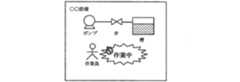
図1において、1は中央監視室10に設けられ、オペレータがプラントの状態を監視し制御するための監視装置、2はプラントを制御する制御装置、3はサーバ、4は現場である地下の機械室20に設けられ、現場作業員7の移動状態を撮像するためのITVカメラ、5はスピーカである。なお、これらの監視装置1、制御装置2、サーバ3、ITVカメラ4、スピーカ5は、例えばLANなどの通信網により接続されている。 In FIG. 1,
現場作業員7がメンテナンスあるいは修繕作業のため、現場である地下の機械室20に入ると、メンテナンスあるいは修繕作業中に予期しない機器が動作することによる危険性をなくすため、現場作業員に作業対象機器に関連する周辺機器の運用情報をスピーカ5で通知する。現場作業員7の移動状態はITVカメラ4で撮像され、撮像された画像情報はサーバ3に送られ、サーバ3では送られた画像情報を分析し、現場作業員7の位置を検知する。サーバ3では、検知した現場作業員7の位置情報をプラント監視用のデータベース(図示せず)に保存されている情報と比較処理する。プラント監視用のデータベースは、監視装置1と制御装置2から入力される機器運用情報を保存しているものである。 When the site worker 7 enters the
サーバ3では現場作業員7の位置と機器8を運用した場合の影響範囲とを比較し、現場作業員7に危険性が及ぶ運用と判断した場合、すなわち、現場作業員7が誤って運用する機器8の近辺の危険領域9に近づいたと判断した場合、サーバ3ではこれを検知し、警告情報を監視装置1およびスピーカ5に送出する。監視装置1では、監視画面に、現場作業員7が機器8の近辺の危険領域9に近づいたことを、例えば図2に示すように、シンボル、メッセージ、警報などで表示する。監視画面でプラントを監視しているオペレータは、監視画面に現場作業員が表示されることで、どの機器の近くに現場作業員7がいるか確認できるので、機器の操作をする際に注意出来る。また、操作を行う際、オペレータに「近くで現場作業員が作業中ですので、現場作業員に確認してから操作してください。」とのガイダンスを流し、現場作業員からの確認を受けた後でないとオペレータの操作ができない仕組みも可能である。 The
また、現場である地下の機械室20のスピーカ5から、現場作業員7に危険であることを報知する。また、スピーカ5からの報知に加えて、機械室20内に設置した回転灯を点滅させて危険を報知するようにしてもよい。 In addition, the site worker 7 is informed of the danger from the speaker 5 in the
なお、上述の説明では、現場作業員7の移動状態をITVカメラ4で撮像して、この画像情報から現場作業員7の位置を検知することとしたが、ITVカメラ4の代わりに、赤外線センサを用いて、現場作業員7すなわち37℃位の物体の移動状態を感知し、この赤外線センサで得られた情報から、現場作業員7の位置を検知するように構成することもできる。また、ITVカメラと赤外線センサとを併用して、これらから得られた情報を複合的に組み合わせることにより、現場作業員7の位置を、より正確に検知することもできる。 In the above description, the moving state of the field worker 7 is imaged by the ITV camera 4 and the position of the field worker 7 is detected from this image information. However, instead of the ITV camera 4, an infrared sensor is used. It is also possible to detect the position of the field worker 7 by detecting the moving state of the field worker 7, that is, an object at about 37 ° C., and from the information obtained by the infrared sensor. Moreover, the position of the on-site worker 7 can be detected more accurately by combining the information obtained from the ITV camera and the infrared sensor in combination.
また、地下の機械室20内のほぼ全域を危険領域として設定する場合は、機械室20の出入り口に、現場作業員7の出入りを検知するセンサを設置し、このセンサにより現場作業員7が機械室20に入ることを検知したとき、現場作業員7が危険領域に近づいたものと判断して、この情報を監視装置1およびスピーカ5に送出し、上述の場合と同様に、監視装置1の監視画面および機械室20のスピーカ5で報知することとすればよい。 When almost the entire area inside the
以上説明したように、この実施形態によれば、GPSの電波が届かない地下の機械室等においても、現場作業員の位置を検知し、この位置情報に基づき現場作業員が危険領域に近づいたことを監視画面に表示してオペレータに報知し、また現場作業員に危険を報知することができる。 As described above, according to this embodiment, even in an underground machine room or the like where GPS radio waves do not reach, the position of the field worker is detected, and based on this position information, the field worker approaches the danger area. This can be displayed on the monitoring screen to notify the operator, and the worker can be notified of the danger.
(第2の実施形態)
次に、本発明に係るプラント監視システムの第2の実施形態について説明する。この第2の実施形態は、上述の第1の実施形態の構成および動作に加えて、現場作業員の位置情報を監視制御に取り込み、制御装置2のプラント制御へのインターロックの有効/無効の切替スイッチ6を機械室20内に設け、インターロックを有効にすることで、現場作業の危険につながる制御を停止するようにしたものである。(Second Embodiment)
Next, a second embodiment of the plant monitoring system according to the present invention will be described. In the second embodiment, in addition to the configuration and operation of the first embodiment described above, the position information of the on-site worker is taken into the supervisory control, and the interlock / effectiveness of the interlock to the plant control of the
この実施形態においても、上述の第1の実施形態の場合と同様に、ITVカメラ4(または、赤外線センサ、機械室20の出入り口に設置された出入りを検知するセンサ)からの情報により、現場作業員7の位置情報を、サーバ3で検知する。サーバ3では、検知した現場作業員7の位置情報をプラント監視用のデータベース(図示せず)に保存されている情報と比較処理し、現場作業員7に危険性が及ぶ運用と判断した場合、すなわち、現場作業員7が誤って、運用する機器8の近辺の危険領域9に近づいた場合、サーバ3ではこれを検知し、警告情報を監視装置1およびスピーカ5に送出する。 In this embodiment as well, in the same manner as in the first embodiment described above, the field work is performed based on information from the ITV camera 4 (or an infrared sensor, a sensor that detects entry / exit installed at the entrance / exit of the machine room 20). The
更に、この実施形態においては、機械室20内に、プラント制御のインターロックの有効/無効を切替える切替用押釦スイッチ6が設置されている。通常は、この切替用押釦スイッチ6が有効の側に切替えられていて、サーバ3は、現場作業員7の位置と、機器8を運用した場合の影響範囲とを比較し、現場作業員7に危険性が及ぶ運用と判断した場合、すなわち、現場作業員7が誤って、運用する機器8の近辺の危険領域9に近づいたと判断した場合、制御装置2に制御条件のインターロック信号が送信され、制御装置2で自動的に危険な運用が出来ないようにインターロック動作を行う。 Furthermore, in this embodiment, a switching pushbutton switch 6 for switching the validity / invalidity of the plant control interlock is installed in the
一方、現場作業員7が、機器8を運用した場合の危険性を認識した上で、機器8の点検などを行う場合は、切替用押釦スイッチ6を押して無効の側に切替える。このように切替えると、制御装置2にインターロックを無効とする信号が送られて制御装置2ではインターロック動作が解除され、現場作業員7が機器8の近辺の危険領域9に近づいても、機器8の運用が通常通り行われ、現場作業員7は、機器8が運用されたまま、機器8の点検などを行うことができる。 On the other hand, when the field worker 7 checks the equipment 8 after recognizing the danger when operating the equipment 8, the switching push button switch 6 is pressed to switch to the invalid side. When switching in this way, a signal to invalidate the interlock is sent to the
以上説明したように、この実施形態によれば、現場操作員7が現場作業を実施するにあたり、危険を及ぼす機器が突然運用されないように制御装置2にインターロック動作を行う手段を設けるので、現場作業員7が安全に作業できる。また、現場操作員7とオペレータとの事前の連絡等により、現場作業員7が機器を運用した場合の危険性を認識した上で、切替用押釦スイッチ6によりインターロックを無効とすれば、インターロック動作が行われることなく、オペレータの操作などにより機器8を運用したままの状態で、現場作業員7により機器8の点検などを行うことが可能となる。 As described above, according to this embodiment, when the field operator 7 performs the field work, the
1…監視装置
2…制御装置
3…サーバ
4…ITVカメラ
5…スピーカ
6…切替用押釦スイッチ
7…現場作業員
8…機器
9…危険領域
10…中央監視室
20…現場(地下の機械室)DESCRIPTION OF
Claims (4)
Translated fromJapanesePriority Applications (1)
| Application Number | Priority Date | Filing Date | Title |
|---|---|---|---|
| JP2007309665AJP2009134488A (en) | 2007-11-30 | 2007-11-30 | Plant monitoring system |
Applications Claiming Priority (1)
| Application Number | Priority Date | Filing Date | Title |
|---|---|---|---|
| JP2007309665AJP2009134488A (en) | 2007-11-30 | 2007-11-30 | Plant monitoring system |
Publications (1)
| Publication Number | Publication Date |
|---|---|
| JP2009134488Atrue JP2009134488A (en) | 2009-06-18 |
Family
ID=40866313
Family Applications (1)
| Application Number | Title | Priority Date | Filing Date |
|---|---|---|---|
| JP2007309665APendingJP2009134488A (en) | 2007-11-30 | 2007-11-30 | Plant monitoring system |
Country Status (1)
| Country | Link |
|---|---|
| JP (1) | JP2009134488A (en) |
Cited By (15)
| Publication number | Priority date | Publication date | Assignee | Title |
|---|---|---|---|---|
| CN101986356A (en)* | 2010-11-03 | 2011-03-16 | 云南大红山管道有限公司 | Dangerous source area personnel monitoring and warning device |
| JP2012203677A (en)* | 2011-03-25 | 2012-10-22 | Penta Ocean Construction Co Ltd | Safety management system |
| JP2014016801A (en)* | 2012-07-09 | 2014-01-30 | Toshiba Corp | Maintenance assistance system for power system installation |
| WO2014182887A1 (en)* | 2013-05-08 | 2014-11-13 | International Electronic Machines Corporation | Operations monitoring in an area |
| CN104483949A (en)* | 2014-12-16 | 2015-04-01 | 大连久鹏电子系统工程有限公司 | Remote monitoring system for small distributed environment-friendly equipment |
| JP2015106127A (en)* | 2013-12-02 | 2015-06-08 | トヨタ自動車株式会社 | Training system and training method |
| JP2016535256A (en)* | 2013-10-16 | 2016-11-10 | スタトイル・ペトロリウム・アーエスStatoil Petroleum As | Noise surveillance system |
| JP2017046209A (en)* | 2015-08-27 | 2017-03-02 | 富士通株式会社 | Image processing apparatus, image processing method, and image processing program |
| JP2019106010A (en)* | 2017-12-12 | 2019-06-27 | 中国電力株式会社 | Charge proximity sensing device, charge proximity sensing method, and charge proximity sensing system |
| CN111191631A (en)* | 2020-01-08 | 2020-05-22 | 哈尔滨融智爱科智能科技有限公司 | Video monitoring supervision area multi-device linkage method based on image domain template matching |
| CN113554846A (en)* | 2020-04-24 | 2021-10-26 | 深圳市中兴系统集成技术有限公司 | Comprehensive security system method and device based on intelligent wearing |
| JP7032601B1 (en) | 2021-09-03 | 2022-03-08 | 株式会社Social Area Networks | Work monitoring system and work monitoring method |
| JP2022187197A (en)* | 2021-06-07 | 2022-12-19 | 東芝三菱電機産業システム株式会社 | Plant equipment monitoring device |
| US12154342B2 (en) | 2020-01-29 | 2024-11-26 | Nec Corporation | Surveillance system, surveillance apparatus, surveillance method, and non-transitorycomputer-readable storage medium |
| US12198436B2 (en) | 2019-12-27 | 2025-01-14 | Nec Corporation | Display system, display processing method, and nontransitory computer-readable storage medium |
Citations (5)
| Publication number | Priority date | Publication date | Assignee | Title |
|---|---|---|---|---|
| JPS607593A (en)* | 1983-06-27 | 1985-01-16 | 三菱電機株式会社 | Intrusion monitoring device |
| JPH10162256A (en)* | 1996-11-28 | 1998-06-19 | Matsushita Electric Works Ltd | Burglar system |
| JP2002082747A (en)* | 2000-09-06 | 2002-03-22 | Toshiba Corp | Monitoring and control equipment |
| JP2003272061A (en)* | 2002-03-13 | 2003-09-26 | Omron Corp | Monitor |
| JP2004265197A (en)* | 2003-03-03 | 2004-09-24 | Nippon Yusoki Co Ltd | Interlock releasing device |
- 2007
- 2007-11-30JPJP2007309665Apatent/JP2009134488A/enactivePending
Patent Citations (5)
| Publication number | Priority date | Publication date | Assignee | Title |
|---|---|---|---|---|
| JPS607593A (en)* | 1983-06-27 | 1985-01-16 | 三菱電機株式会社 | Intrusion monitoring device |
| JPH10162256A (en)* | 1996-11-28 | 1998-06-19 | Matsushita Electric Works Ltd | Burglar system |
| JP2002082747A (en)* | 2000-09-06 | 2002-03-22 | Toshiba Corp | Monitoring and control equipment |
| JP2003272061A (en)* | 2002-03-13 | 2003-09-26 | Omron Corp | Monitor |
| JP2004265197A (en)* | 2003-03-03 | 2004-09-24 | Nippon Yusoki Co Ltd | Interlock releasing device |
Cited By (20)
| Publication number | Priority date | Publication date | Assignee | Title |
|---|---|---|---|---|
| CN101986356A (en)* | 2010-11-03 | 2011-03-16 | 云南大红山管道有限公司 | Dangerous source area personnel monitoring and warning device |
| JP2012203677A (en)* | 2011-03-25 | 2012-10-22 | Penta Ocean Construction Co Ltd | Safety management system |
| JP2014016801A (en)* | 2012-07-09 | 2014-01-30 | Toshiba Corp | Maintenance assistance system for power system installation |
| US10597053B2 (en) | 2013-05-08 | 2020-03-24 | International Electronic Machines Corp. | Operations monitoring in an area |
| WO2014182887A1 (en)* | 2013-05-08 | 2014-11-13 | International Electronic Machines Corporation | Operations monitoring in an area |
| US10627283B2 (en) | 2013-10-16 | 2020-04-21 | Statoil Petroleum As | Noise surveillance system |
| JP2016535256A (en)* | 2013-10-16 | 2016-11-10 | スタトイル・ペトロリウム・アーエスStatoil Petroleum As | Noise surveillance system |
| JP2015106127A (en)* | 2013-12-02 | 2015-06-08 | トヨタ自動車株式会社 | Training system and training method |
| US10029173B2 (en) | 2013-12-02 | 2018-07-24 | Toyota Jidosha Kabushiki Kaisha | Training system and training method |
| CN104483949A (en)* | 2014-12-16 | 2015-04-01 | 大连久鹏电子系统工程有限公司 | Remote monitoring system for small distributed environment-friendly equipment |
| JP2017046209A (en)* | 2015-08-27 | 2017-03-02 | 富士通株式会社 | Image processing apparatus, image processing method, and image processing program |
| JP2019106010A (en)* | 2017-12-12 | 2019-06-27 | 中国電力株式会社 | Charge proximity sensing device, charge proximity sensing method, and charge proximity sensing system |
| US12198436B2 (en) | 2019-12-27 | 2025-01-14 | Nec Corporation | Display system, display processing method, and nontransitory computer-readable storage medium |
| CN111191631A (en)* | 2020-01-08 | 2020-05-22 | 哈尔滨融智爱科智能科技有限公司 | Video monitoring supervision area multi-device linkage method based on image domain template matching |
| US12154342B2 (en) | 2020-01-29 | 2024-11-26 | Nec Corporation | Surveillance system, surveillance apparatus, surveillance method, and non-transitorycomputer-readable storage medium |
| CN113554846A (en)* | 2020-04-24 | 2021-10-26 | 深圳市中兴系统集成技术有限公司 | Comprehensive security system method and device based on intelligent wearing |
| JP2022187197A (en)* | 2021-06-07 | 2022-12-19 | 東芝三菱電機産業システム株式会社 | Plant equipment monitoring device |
| JP7515987B2 (en) | 2021-06-07 | 2024-07-16 | 株式会社Tmeic | Plant equipment monitoring device |
| JP7032601B1 (en) | 2021-09-03 | 2022-03-08 | 株式会社Social Area Networks | Work monitoring system and work monitoring method |
| JP2023037366A (en)* | 2021-09-03 | 2023-03-15 | 株式会社Social Area Networks | Work monitoring system and work monitoring method |
Similar Documents
| Publication | Publication Date | Title |
|---|---|---|
| JP2009134488A (en) | Plant monitoring system | |
| KR101570640B1 (en) | Remote monitoring system for high voltage package switchgear, low voltage package switchgear, distribute board, motor control center using the thermal imaging camera | |
| JP4137932B2 (en) | Robot controller | |
| KR101587491B1 (en) | Safety Maintenance System for Power Plant Electric Equipment | |
| JP2011095848A (en) | Accident prevention monitoring control system | |
| EP1403010A2 (en) | Robot system comprising an operator detection unit | |
| CN109502439A (en) | It is limited to enter region security system | |
| KR20120096386A (en) | Apparatus for alarming dangerous zone and safety management system using thereof | |
| JP2008234318A (en) | Facility operation system | |
| CN102574661A (en) | Notification device of elevator | |
| KR101935798B1 (en) | System for managing danger using beacon transmitter and method thereof | |
| JP2007223730A (en) | Elevator control device | |
| JP2005289309A (en) | Train approach warning system | |
| JP2024539119A (en) | Method for identifying rule-violating behavior and intelligent sensor system for preventing rule-violating behavior - Patents.com | |
| KR20230033279A (en) | Industrial site disaster prevention system and method | |
| JP2018177395A (en) | Remote monitoring system of lifting device | |
| JP2019018993A (en) | Passenger conveyor alarm system | |
| JP4395829B2 (en) | Automatic machine operation permission device | |
| JP2002082747A (en) | Monitoring and control equipment | |
| KR101168021B1 (en) | Alarm method and system for abnormalty of ship and ship having the system | |
| JP2009271891A (en) | Maintenance inspection support device | |
| KR101638896B1 (en) | System and Method for Supporting Decision Making and Incident Managing | |
| CN209028164U (en) | Error-proof system for cable withstand voltage test | |
| JP5175237B2 (en) | Equipment signal inspection adapter, equipment signal inspection method | |
| JP6624521B2 (en) | Remote monitoring system for lifting equipment |
Legal Events
| Date | Code | Title | Description |
|---|---|---|---|
| A621 | Written request for application examination | Free format text:JAPANESE INTERMEDIATE CODE: A621 Effective date:20100129 | |
| A977 | Report on retrieval | Effective date:20111111 Free format text:JAPANESE INTERMEDIATE CODE: A971007 | |
| A131 | Notification of reasons for refusal | Free format text:JAPANESE INTERMEDIATE CODE: A131 Effective date:20111206 | |
| A02 | Decision of refusal | Free format text:JAPANESE INTERMEDIATE CODE: A02 Effective date:20120404 |