JP2009133472A - Variable damping force damper - Google Patents
Variable damping force damperDownload PDFInfo
- Publication number
- JP2009133472A JP2009133472AJP2008062301AJP2008062301AJP2009133472AJP 2009133472 AJP2009133472 AJP 2009133472AJP 2008062301 AJP2008062301 AJP 2008062301AJP 2008062301 AJP2008062301 AJP 2008062301AJP 2009133472 AJP2009133472 AJP 2009133472A
- Authority
- JP
- Japan
- Prior art keywords
- piston
- inner yoke
- yoke
- damping force
- coil
- Prior art date
- Legal status (The legal status is an assumption and is not a legal conclusion. Google has not performed a legal analysis and makes no representation as to the accuracy of the status listed.)
- Pending
Links
Images


Classifications
- B—PERFORMING OPERATIONS; TRANSPORTING
- B60—VEHICLES IN GENERAL
- B60G—VEHICLE SUSPENSION ARRANGEMENTS
- B60G17/00—Resilient suspensions having means for adjusting the spring or vibration-damper characteristics, for regulating the distance between a supporting surface and a sprung part of vehicle or for locking suspension during use to meet varying vehicular or surface conditions, e.g. due to speed or load
- B60G17/06—Characteristics of dampers, e.g. mechanical dampers
- B—PERFORMING OPERATIONS; TRANSPORTING
- B60—VEHICLES IN GENERAL
- B60G—VEHICLE SUSPENSION ARRANGEMENTS
- B60G21/00—Interconnection systems for two or more resiliently-suspended wheels, e.g. for stabilising a vehicle body with respect to acceleration, deceleration or centrifugal forces
- B60G21/02—Interconnection systems for two or more resiliently-suspended wheels, e.g. for stabilising a vehicle body with respect to acceleration, deceleration or centrifugal forces permanently interconnected
- B60G21/04—Interconnection systems for two or more resiliently-suspended wheels, e.g. for stabilising a vehicle body with respect to acceleration, deceleration or centrifugal forces permanently interconnected mechanically
- B60G21/05—Interconnection systems for two or more resiliently-suspended wheels, e.g. for stabilising a vehicle body with respect to acceleration, deceleration or centrifugal forces permanently interconnected mechanically between wheels on the same axle but on different sides of the vehicle, i.e. the left and right wheel suspensions being interconnected
- B60G21/051—Trailing arm twist beam axles
- F—MECHANICAL ENGINEERING; LIGHTING; HEATING; WEAPONS; BLASTING
- F16—ENGINEERING ELEMENTS AND UNITS; GENERAL MEASURES FOR PRODUCING AND MAINTAINING EFFECTIVE FUNCTIONING OF MACHINES OR INSTALLATIONS; THERMAL INSULATION IN GENERAL
- F16F—SPRINGS; SHOCK-ABSORBERS; MEANS FOR DAMPING VIBRATION
- F16F9/00—Springs, vibration-dampers, shock-absorbers, or similarly-constructed movement-dampers using a fluid or the equivalent as damping medium
- F16F9/32—Details
- F16F9/53—Means for adjusting damping characteristics by varying fluid viscosity, e.g. electromagnetically
- F16F9/535—Magnetorheological [MR] fluid dampers
- B—PERFORMING OPERATIONS; TRANSPORTING
- B60—VEHICLES IN GENERAL
- B60G—VEHICLE SUSPENSION ARRANGEMENTS
- B60G2202/00—Indexing codes relating to the type of spring, damper or actuator
- B60G2202/20—Type of damper
- B60G2202/24—Fluid damper
Landscapes
- Engineering & Computer Science (AREA)
- Mechanical Engineering (AREA)
- General Engineering & Computer Science (AREA)
- Physics & Mathematics (AREA)
- Electromagnetism (AREA)
- Fluid-Damping Devices (AREA)
Abstract
Translated fromJapaneseDescription
Translated fromJapanese本発明は、自動車用サスペンションを構成するテレスコピック式の減衰力可変ダンパに係り、詳しくは、減衰力の可変幅を大きくする技術に関する。 The present invention relates to a telescopic variable damping force damper that constitutes a suspension for an automobile, and more particularly to a technique for increasing the variable range of the damping force.
近年、自動車のサスペンションに用いられる筒型ダンパでは、乗り心地や操縦安定性の向上を図るべく、減衰力の可変制御が可能な減衰力可変ダンパが種々開発されている。減衰力可変ダンパとしては、オリフィス面積を変化させるロータリバルブをピストンに設け、このロータリバルブをアクチュエータによって回転駆動する機械式のものが主流であったが、構成の簡素化や応答性の向上等を実現すべく、作動液に磁気粘性流体を用い、ピストンと一体に形成された磁気流体バルブによって磁気粘性流体の粘度を制御するものが出現している(特許文献1参照)。 2. Description of the Related Art In recent years, various types of damping force variable dampers capable of variable damping force control have been developed for cylindrical dampers used in automobile suspensions in order to improve riding comfort and steering stability. As the damping force variable damper, a mechanical type in which a rotary valve that changes the orifice area is provided on the piston and this rotary valve is driven to rotate by an actuator has been the mainstream, but simplification of the configuration and improvement of responsiveness etc. In order to achieve this, there has been a technology in which a magnetorheological fluid is used as a working fluid and the viscosity of the magnetorheological fluid is controlled by a magnetorheological valve formed integrally with a piston (see Patent Document 1).
特許文献1の減衰力可変ダンパでは、ピストンが、外周にコイルが巻き回された円柱状のインナヨークと、インナヨークの両端に配置された一対のエンドプレートと、インナヨークと両エンドプレートを収容する円筒状のアウタヨークとから主に構成されている。インナヨークおよびアウタヨークはともに強磁性体を素材としており、エンドプレートによって保持されることによって両者の間に環状流路が形成される。エンドプレートは、非磁性体を素材とした円盤状のものであり、環状流路に連通する複数の円弧状孔と、インナヨーク端部の凸部が係合する環状凹部と、ピストンロッド固定用のリングが係合する環状溝とを有している。また、インナヨークおよびエンドプレートは、アウタヨークの両端外縁を加締めることによって固定されている。
このような減衰力可変ダンパに於いては、好適な或いは広範囲の用途に適用可能なものであるためには、減衰力の可変幅が大きく、かつ応答性が良好であることが望まれる。特許文献2及び特許文献3には、ピストンの外周に軸線方向溝を設け、非通電時の減衰力を小さくしたり、ピストン速度に対する減衰力を最適化することが提案されている。
一般に、減衰力の可変幅を大きくし、非通電時の減衰力を小さくすると良く、応答性を向上させるためには、コイルのインダクタンスを小さくすると良い。しかしながら、実際には、非通電時の減衰力を効果的に小さくすることが困難であり、減衰力の応答性に遅れが出る等の問題があった。 In general, the variable range of the damping force should be increased to reduce the damping force when no current is applied. In order to improve the response, the coil inductance should be reduced. However, in practice, it is difficult to effectively reduce the damping force when the power is not supplied, and there is a problem that the response of the damping force is delayed.
その原因としては、従来のMRFを用いた可変減衰力ダンパは減衰力を発生させる流路の中間部にコイルを配置していたため流路全長が長くなってしまい、結果電流を通電しないときの減衰力が大きくなってしまい、乗り心地性能を悪化させていたという問題があった、また、従来のMRFを用いた可変減衰力ダンパでは、コイルを流路内周面近傍に配置しており、インダクタンスが大きくなり制御指示電流に対する減衰力の応答性を悪化させていた。 The reason is that the variable damping force damper using the conventional MRF has a coil disposed in the middle part of the flow path that generates the damping force, so that the total length of the flow path becomes long, resulting in the attenuation when no current is passed. In the conventional variable damping force damper using the MRF, the coil is arranged in the vicinity of the inner peripheral surface of the flow path, resulting in a problem that the force is increased and the ride comfort performance is deteriorated. As a result, the response of the damping force to the control command current deteriorated.
このような従来技術の問題点に鑑み、本発明の主な目的は、MRFを用いた可変減衰力ダンパに於いて、電流を通電しないときの減衰力を小さくすることにより、車両の乗り心地性能を向上させることにある。 In view of such problems of the prior art, the main object of the present invention is to reduce the damping force when current is not applied in a variable damping force damper using MRF, thereby improving the riding comfort performance of the vehicle. Is to improve.
本発明の第2の目的は、MRFを用いた可変減衰力ダンパに於いて、コイルのインダクタンスを小さくして、制御指示電流に対する減衰力の応答性を向上させることにある。 The second object of the present invention is to improve the responsiveness of the damping force to the control command current by reducing the inductance of the coil in the variable damping force damper using the MRF.
このような目的は、本発明によれば、磁性流体または磁気粘性流体が充填されるとともに車体側部材と車輪側部材とのどちらか一方に連結されたシリンダと、前記シリンダを一側液室と他側液室とに区画するとともに前記磁性流体または磁気粘性流体を当該一側液室と他側液室との間で流通させる流路が形成されたピストンと、前記車体側部材と車輪側部材とのどちらか他方を当該ピストンに連結するピストンロッドとを有し、前記流路を通過する前記磁性流体または前記磁気粘性流体に磁界を印加することで減衰力が制御される減衰力可変式ダンパであって、前記ピストンは、前記ピストンの外周側部分を形成するアウタヨークと、前記アウタヨークの内側に所定の間隙をもって設置され、当該アウタヨークとの間に前記流路を画成するインナヨークと、前記インナヨークに保持され、前記磁界の形成に供されるコイルとを備え、前記コイルが、前記インナヨークの外周に凹設された環状溝内に受容され、かつ前記インナヨークが、前記コイルの外周に向けてオーバハングするように、前記環状溝の外周部側にて軸線方向延出部を有することを特徴とする減衰力可変ダンパを提供することにより達成される。 According to the present invention, such an object is achieved by a cylinder filled with a magnetic fluid or a magnetorheological fluid and connected to one of a vehicle body side member and a wheel side member, and the cylinder as a side liquid chamber. A piston formed with a flow path for dividing the magnetic fluid or the magnetorheological fluid between the one-side liquid chamber and the other-side liquid chamber, and the vehicle body-side member and the wheel-side member. And a piston rod that connects the other to the piston, and a damping force variable damper whose damping force is controlled by applying a magnetic field to the magnetic fluid or the magnetorheological fluid passing through the flow path The piston is installed with an outer yoke forming an outer peripheral side portion of the piston and a predetermined gap inside the outer yoke, and the flow path is defined between the piston and the outer yoke. A coil that is held by the inner yoke and used for forming the magnetic field, the coil is received in an annular groove that is recessed in the outer periphery of the inner yoke, and the inner yoke is This is achieved by providing a variable damping force damper having an axially extending portion on the outer peripheral portion side of the annular groove so as to overhang toward the outer periphery.
この場合、前記インナヨークの前記軸線方向延出部が、前記環状溝の両側から略対称に延出するものとすれば、インナヨークとアウタヨークとの間に形成される空隙内にて、強い磁界を均一に形成することができ、高い磁気効率を確保することができる。 In this case, if the axially extending portion of the inner yoke extends substantially symmetrically from both sides of the annular groove, a strong magnetic field is uniformly generated in the gap formed between the inner yoke and the outer yoke. And high magnetic efficiency can be ensured.
このような目的は、また、本発明によれば、磁性流体または磁気粘性流体が充填されるとともに車体側部材と車輪側部材とのどちらか一方に連結されたシリンダと、前記シリンダを一側液室と他側液室とに区画するとともに前記磁性流体または磁気粘性流体を当該一側液室と他側液室との間で流通させる流路が形成されたピストンと、前記車体側部材と車輪側部材とのどちらか他方を当該ピストンに連結するピストンロッドとを有し、前記流路を通過する前記磁性流体または前記磁気粘性流体に磁界を印加することで減衰力が制御される減衰力可変式ダンパであって、前記ピストンは、前記ピストンの外周側部分を形成するアウタヨークと、前記アウタヨークの内側に所定の間隙をもって設置され、当該アウタヨークとの間に前記流路を画成するインナヨークと、前記インナヨークに保持され、前記磁界の形成に供されるコイルとを備え、 前記インナヨークに保持され、前記磁界の形成に供されるコイルとを備え、前記コイルの外周側に於ける前記インナヨークの軸線方向長が、少なくとも部分的に、前記コイルを通過する前記インナヨークの軸線方向長よりも大きいことを特徴とする減衰力可変ダンパを提供することによっても達成される。 Another object of the present invention is to provide a cylinder filled with a magnetic fluid or a magnetorheological fluid and connected to one of a vehicle body side member and a wheel side member; A piston that is divided into a chamber and an other-side liquid chamber and that has a flow path through which the magnetic fluid or the magnetorheological fluid flows between the one-side liquid chamber and the other-side liquid chamber, the vehicle body-side member, and the wheel A damping rod having a piston rod that connects one of the side member and the piston to the piston, and the damping force is controlled by applying a magnetic field to the magnetic fluid or the magnetorheological fluid passing through the flow path. The piston is provided with an outer yoke forming an outer peripheral side portion of the piston and a predetermined gap inside the outer yoke, and defines the flow path between the outer yoke and the outer yoke. An inner yoke and a coil held by the inner yoke and used for forming the magnetic field, and a coil held by the inner yoke and used for forming the magnetic field. It is also achieved by providing a damping force variable damper characterized in that the axial length of the inner yoke is at least partially larger than the axial length of the inner yoke passing through the coil.
このようにすれば、MRFを用いた可変減衰力ダンパに於いて、環状溝の開口部分に形成される磁気的に無効な部分の軸線方向長を最小化し得ることから、MRFのピストンを横切る流路長を短縮し、電流を通電しないときの減衰力を小さくすることができる。それにより、車両の乗り心地性能を向上させることができる。また、コイルを、流路内周面からやや離反した、半径方向内側に配置することができ、コイルのインダクタンスを小さくして、制御指示電流に対する減衰力の応答性を向上させることができる。また、磁気的に無効な部分の軸線方向長を最小化することにより、ピストンの全体的な軸線方向長を短縮し得る効果も得られ、ダンパのコンパクト化に寄与することができる。 In this way, in the variable damping force damper using the MRF, the axial length of the magnetically ineffective portion formed in the opening portion of the annular groove can be minimized, so that the flow across the piston of the MRF The path length can be shortened, and the damping force when no current is supplied can be reduced. Thereby, the riding comfort performance of the vehicle can be improved. In addition, the coil can be arranged on the inner side in the radial direction, slightly separated from the inner peripheral surface of the flow path, and the coil inductance can be reduced and the response of the damping force to the control command current can be improved. Further, by minimizing the axial length of the magnetically ineffective portion, the effect of shortening the overall axial length of the piston can be obtained, which can contribute to the compactness of the damper.
特に、前記インナヨークが軸方向で分割され、かつ締結部材によって締結/一体化される少なくとも2つの部分からなるものであると良い。このようにすれば、環状溝の外周部側にてコイルの外周に向けてオーバハングする軸線方向延出部を設けた場合でも、コイルを環状溝内に容易に組み付けることができる。 In particular, the inner yoke is preferably composed of at least two parts that are divided in the axial direction and fastened / integrated by a fastening member. In this way, even when an axially extending portion overhanging toward the outer periphery of the coil is provided on the outer peripheral portion side of the annular groove, the coil can be easily assembled in the annular groove.
以下、図面を参照して、本発明を4輪自動車のリヤサスペンションに適用した実施形態を詳細に説明する。 Hereinafter, an embodiment in which the present invention is applied to a rear suspension of a four-wheel vehicle will be described in detail with reference to the drawings.
図1に示すように、本実施形態のリヤサスペンション1は、いわゆるH型トーションビーム式サスペンションであり、左右のトレーリングアーム2、3や、両トレーリングアーム2、3の中間部を連結するトーションビーム4、懸架ばねである左右一対のコイルスプリング5、左右一対のダンパ6等から構成されており、左右のリヤホイール7、8を懸架している。ダンパ6は、MRF(Magneto-Rheological Fluid:磁気粘性流体)を作動流体とする減衰力可変型ダンパであり、トランクルーム内等に設置されたECU9によってその減衰力が可変制御される。 As shown in FIG. 1, the
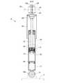
図2に示すように、本実施形態のダンパ6は、モノチューブ式(ド・カルボン式)であり、MRFが充填された円筒状のシリンダ12と、このシリンダ12に対して軸方向に摺動するピストンロッド13と、ピストンロッド13の先端に装着されてシリンダ12内を上部液室(一側液室)14と下部液室(他側液室)15とに区画するピストン16と、シリンダ12の下部に高圧ガス室17を画成するフリーピストン18と、ピストンロッド13等への塵埃の付着を防ぐカバー19と、フルバウンド時における緩衝を行うバンプストップ20とを主要構成要素としている。 As shown in FIG. 2, the
シリンダ12は、下端のアイピース12aに嵌挿されたボルト21を介して、車輪側部材であるトレーリングアーム2の上面に連結されている。また、ピストンロッド13は、上下一対のブッシュ22とナット23とを介して、その上部ねじ軸13aが車体側部材であるダンパベース(ホイールハウス上部)24に連結されている。 The
図3はピストン16の詳細を示す。ピストン16の中心部には、円柱状をなす強磁性体からなるインナヨーク26が設けられ、その一方の軸線方向端に設けられた孔35にピストンロッド13の一端が突入している。インナヨーク26は、軸線方向に分割された2つの部分26a、26bからなり、ピストンロッド13に対して離反する側の軸線方向端面から挿入された計4つの締結ねじ27により互いに一体化されている。 FIG. 3 shows details of the
インナヨーク26の、外周の軸線方向中間部分には環状溝28が設けられ、その内部にコイル30が受容され、樹脂モールド29内に埋め込まれている。この場合コイル30は、インナヨーク26の周方向に巻かれたコイルをなしている。また、環状溝28の外周部側には、コイル30の外周に向けてオーバーハングするようにインナヨーク26の部分が軸線方向に延出することにより形成される軸線方向延出部31が設けられている。図示された実施例では、この軸線方向延出部31は、環状溝28の両側から軸線方向に対称に延出している。このようにして、インナヨーク26の外周部分は、全体として概ね一定半径の円周面をなす外周面を画定すると共に、環状溝28の両側に位置する部分が、インナヨーク26の両部分26a、26bをなしている。 An
また、インナヨーク26の両部分の分割面33は、ピストンロッド13と離反する側の環状溝28の側面と同一面上に位置している。インナヨーク26の、両軸線方向端面には、非磁性体からなり、環状をなすエンドプレート34(34a、34b)が重ね合わされ、ピストンロッド13の側のエンドプレート34aの中心孔を、ピストンロッド13が貫通している。エンドプレート34は、それぞれ外周部に周方向に等間隔に設けられた4つの円弧状スロット36を備えている。 The
更に、両エンドプレート34の外周縁間には、強磁性体からなる円筒状のフラックスリング即ちアウタヨーク40が挟持され、アウタヨーク40の内周面は、インナヨーク26の外周面に対して同心状に所定の間隔の空隙41をおいて対峙している。アウタヨーク40及び両エンドプレート34の、互いに協働して概ね一定半径の円周面をなす外周面には、筒状をなす非磁性体からなるピストンリング43が外装され、かつその両軸線方向端部43a、43bを両エンドプレート34の外周縁に向けてかしめ付け、それによって、両エンドプレート34、インナヨーク26及びアウタヨーク40を互いに一体的に保持している。 Further, a cylindrical flux ring made of a ferromagnetic material, that is, an
更に、ピストンロッド13側のエンドプレート34の内孔のインナヨーク側の縁部には、べべル加工部分37が設けられ対応するピストンロッド13の外周面には環状溝36が設けられている。これらにより画定される環状凹部内にCリング38を嵌め入れることにより、ピストンロッド13を、ピストン16に対して固定している。 Further, a
ピストンロッド13の中心部には、軸線方向孔46が設けられ、インナヨーク26に設けられた同様の中心孔と同軸的に整合している。インナヨーク26のピストンロッド13側部分26aの中心部には凹部47が設けられ、ディスク状の部材からなるハーメチックシール部材45が受容されている。コイル30のリード線44は、ピストンロッド13の中心孔46からインナヨークの中心孔を経て、ハーメチックシール45の中心部をシール可能に通過した後、図示されない、インナヨーク26の両部分26a、26bのいずれか一方の部分の、分割面33側の端面に半径方向に設けられた溝(図示せず)内を通過した後にコイル30に達している。さらに、インナヨーク26とピストンロッド13の突入端との間には、Oリング39が設けられ、ピストンロッド13の中心孔46を作動流体に対してシールするとともに、ハーメチックシール部材45の外周をインナヨーク26の部材に溶接することにより同じく液密なシールを形成している。 An
特に、本実施例に於いては、図4に示されるように、コイルの外周側に於けるインナヨーク26の軸線方向長(Lb1+Lb2:但し、Lb1は同部分に於けるインナヨークの一方の部分26aの軸線方向長であり、Lb2は同部分に於けるインナヨークの他方の部分26bの軸線方向長である。)が、少なくとも部分的に、コイルを通過するインナヨークの軸線方向長(La1+La2:但し、La1はインナヨークの同部分に於ける一方の部分26aの軸線方向長であり、La2はインナヨークの同部分に於ける他方の部分26bの軸線方向長である。)よりも小さい。即ち、(Lb1+Lb2)<(La1+La2)となる。 In particular, in this embodiment, as shown in FIG. 4, the axial length of the
このようにすれば、MRFを用いた可変減衰力ダンパに於いて、環状溝の開口部分に形成される磁気的に無効な部分の軸線方向長を最小化し得ることから、MRFのピストンを横切る流路長を短縮し、電流を通電しないときの減衰力を小さくすることができる。それにより、車両の乗り心地性能を向上させることができる。また、コイルを、流路内周面からやや離反した、半径方向内側に配置することができ、コイルのインダクタンスを小さくして、制御指示電流に対する減衰力の応答性を向上させることができる。また、磁気的に無効な部分の軸線方向長を最小化することにより、ピストンの全体的な軸線方向長を短縮し得る効果も得られ、ダンパのコンパクト化に寄与することができる。 In this way, in the variable damping force damper using the MRF, the axial length of the magnetically ineffective portion formed in the opening portion of the annular groove can be minimized, so that the flow across the piston of the MRF The path length can be shortened, and the damping force when no current is supplied can be reduced. Thereby, the riding comfort performance of the vehicle can be improved. In addition, the coil can be arranged on the inner side in the radial direction, slightly separated from the inner peripheral surface of the flow path, and the coil inductance can be reduced and the response of the damping force to the control command current can be improved. Further, by minimizing the axial length of the magnetically ineffective portion, the effect of shortening the overall axial length of the piston can be obtained, which can contribute to the compactness of the damper.
次に、このダンパ6の作動の要領を説明する。車両の走行などにより、車体に対して車輪が相対変位すると、その変位は、ピストンロッド13を介してピストン16に伝達され、ピストン16とシリンダ12との間に相対変位が引き起こされる。その結果、両液室14、15の容積が変化し、その変化に応じて、MRF(Magneto-Rheological Fluid:磁気粘性流体)が、一方のエンドプレート34aの円弧状スロット36、インナヨーク26とアウタヨーク40との間の空隙41及び他方のエンドプレート34bの円弧状スロット36を通過する。非通電時であれば、MRFは比較的抵抗を受けることなく流れ、概ねピストン16とシリンダ12との間の相対速度に比例する低い減衰力を発生する。コイル30に通電した場合には、MRFがインナヨーク26とアウタヨーク40との間の空隙を通過するときに、空隙41内に形成された磁界により強い流路抵抗が引き起こされ、概ねピストン16とシリンダ12との間の相対速度に比例する高い減衰力を発生する。このような特性を利用し、コイル30に制御された電流を供給することにより、所望のダンパ制御が実現される。 Next, the operation point of the
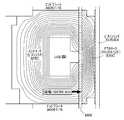
図5は、通電時に、インナヨーク26とアウタヨーク40との間に形成される磁束を示す。これは、インナヨークとアウタヨークの材質をS25C、コイルの材質を銅、ピストンリングの材質をSUS304、エンドプレート材質をA6061−T6、コイル巻き数を50巻としてピストンを構成し、空隙41にMRFが充填された状態で、コイルに5Aの電流を流した場合の磁場をシュミレーションしたものである。この場合、コイル30を受容する環状溝28の外周側が、軸線方向延出部31により、両側から対称的に狭められているが、インナヨーク26とアウタヨーク40との間の空隙41に於いては、空隙の全軸線方向長さに渡って、即ちピストン16の全軸線方向長さに渡って、磁束が平行にしかも実質的に等間隔に形成されている。 FIG. 5 shows the magnetic flux formed between the
図6は、コイル30を受容する環状溝28が、全深さに渡って概ね一定の幅を有し、ピストンの軸線方向長が僅かに長い以外は、図5に於けるピストンと同様の構造を有する従来形式のピストン16に於ける、通電時に、インナヨーク26とアウタヨーク40との間に形成される磁束を示す。図5の場合と同様に、ピストン16の全軸線方向長さに渡って、磁束が平行にしかも実質的に等間隔に形成されているが、環状溝28に対応する部分に於いては、磁束密度が低い部分が形成されている。これは、ピストン16の軸線方向長さの内、環状溝28の幅に対応する部分が磁気的には無効であることを意味する。それに対して、図5に示された、本発明に基づく構成の場合には、ピストン16の軸線方向長さの内、磁気的には無効である部分が最小化される。この場合、環状溝28の最外周の開口幅を過度に小さくすると、磁気的な短絡が生じ、インナヨーク26からアウタヨーク40に至る全体的な磁束が減少し、十分な粘性減衰力が得られなくなる。逆に、環状溝28の最外周の開口幅を過度に大きくすると、磁気的には無効である部分が増大し、非通電時の粘性減衰力を低減する効果が得られない。そこで、実験的に最適な開口幅を求め、それを実際の構造に採用すると良い。 FIG. 6 shows the same structure as the piston in FIG. 5 except that the
特に、本実施例では、軸線方向延出部31が、環状溝28の両側から略対称に延出するものとしたことから、インナヨーク26とアウタヨーク40との間に形成される空隙41内にて、強い磁界を均一に形成することができ、高い磁気効率を確保することができる。必要があれば、軸線方向延出部31の一方が他方よりも長いものとしたり、軸線方向延出部が一方のみから延出するようにすることもできる。 In particular, in the present embodiment, since the
図7は、図5及び図6に示された構造について、他の条件は極力同様となるようにして、電流値が0及び5Aである場合に、それぞれの構造により得られる減衰力を比較したものである。これによれば、非通電時(電流値=0A)には、特にピストン速度が高い領域で、減衰力を従来のものよりもかなり低めることができ、通電時(電流値=5A)には、ピストン速度が低い領域では、やや減衰力を高めることができることが見出された。特に、サスペンションの好適な制御で重要なことは、減衰力の可変幅を大きくし、非通電時の減衰力を小さくすることであることから、図示された実施例は、好適な懸架装置の制御を行なう上で有用である。 FIG. 7 compares the damping force obtained by each structure when the current values are 0 and 5 A, with the other conditions being as similar as possible to the structure shown in FIGS. 5 and 6. Is. According to this, when not energized (current value = 0A), the damping force can be considerably lower than that of the conventional one, particularly in the region where the piston speed is high, and when energized (current value = 5A), It has been found that the damping force can be slightly increased in the region where the piston speed is low. In particular, since the important thing in the preferred control of the suspension is to increase the variable range of the damping force and to reduce the damping force when not energized, the illustrated embodiment is suitable for controlling the suspension system. It is useful for performing.
図8及び9は、本発明のダンパ6の第2の実施形態に於けるピストン16の詳細を示す。図8及び9に於いては、前記実施例に対応する部分には同様の符合を付し、その詳しい説明を省略する。 8 and 9 show details of the
この場合、インナヨーク26は、前記実施例と同様に、軸線方向両端部から互いに組み合わされた2つの部分からなるが、ピストンロッド13側の第1の部分26aの、ピストンロッド13から離反する側の端部の中心部には、雌ねじ孔49が設けられ、第2の部分26bの、雌ねじ孔49に対向する部分には、雄ねじ突部48が設けられ、かつ雌ねじ孔49に螺合されている。第2の部分26bの外側の軸線方向端部の中心には、インナヨーク26の両部分を互いに螺合して締結するための工具を係合するための凹部50が設けられている。 In this case, the
インナヨーク26の両部分26a、26bの互いに離反する側の軸線方向端面外周には、半径方向フランジ25a、25bが設けられ、これらフランジ25a、25b間には、エンドピース32を介して、強磁性体からなる円筒状のフラックスリング即ちアウタヨーク40が挟持されている。即ち、インナヨーク26の両部分26a、26bを互いに捩じ込むことにより、両フランジ25a、25b間に、エンドピース32及びアウタヨーク40が緩みなく挟持されるようになっている。エンドピース32は、非磁性体からなり、それぞれ周方向に等間隔に設けられた4つの円弧状スロット36を備えている。また、アウタヨーク40の内周面は、インナヨーク26の外周面に対して同心状に所定の間隔の空隙41をおいて対峙している。エンドピース32及びアウタヨーク40の外周面は、互いに協働して、ピストン16の外周面を画定している。この外周面自体がピストン16の摺動面をなすものでも、或いは別途図示されないピストンリング部材或いはコーティングを用いて、それをピストン16の摺動面とすることもできる。
更に、ピストンロッド13は、インナヨーク26の対向端面の中心に設けられた凹部35の底面に対して、摩擦圧接法により結合されている。摩擦圧接法とは、接合する部材(たとえば金属や樹脂など)を高速で擦り合わせ、その
とき生じる摩擦熱によって部材を軟化させると同時に圧力を加えて接合する技術である。Further, the
図10に最も良く示されているように、コイル30は、インナヨーク26の両部分間に画定された環状空間内に、樹脂モールド29により保持されている。樹脂モールド29は、環状の本体部分56に加えて、本体部分56のピストンロッド13側の端面に対して、直径線方向に架設された直径部分51と、該直径部分の中心からピストンロッド13に向けて突出する大径ロッド部52と、大径ロッド部の遊端面から同軸的に突出する小径ロッド部53とを有する。コイル30のリード線44は、コイル30から、直径部分51を経て、大径ロッド部52及び小径ロッド部53の内部を通過して、ピストンロッド13の内孔46内から外部に引き出されている。 As best shown in FIG. 10, the
また、小径ロッド部53は、インナヨーク26の第1の部分26a内の中心孔54内に突入し、かつ両部分間にOリング55が挟持され、これにより、リード線44を引き出すために設けられたピストンロッド13の内孔46を、ダンパ内のMRF流体に対してシールしている。 Further, the small-
図11は、本発明のダンパ6の第3の実施形態に於けるピストン16の詳細を示す。図11に於いては、前記実施例に対応する部分には同様の符合を付し、その詳しい説明を省略する。 FIG. 11 shows the details of the
本実施例に於いては、インナヨーク26の第1の部分26aの外周から、薄肉円筒部62が、第2の部分26bの方向に延出している。薄肉円筒部62の外周は、インナヨーク26の第1の部分26aの外周の輪郭と同一の円筒面を画定し、薄肉円筒部62の内周は、インナヨーク26の第2の部分26bの外周の輪郭と補完的円筒面を画定し、かつ同外周に対して実質的に隙間無く密接している。インナヨーク26の第2の部分26bの、軸線方向外端近傍の外周には、環状溝63が設けられ、その内部に受容されたOリング64が薄肉円筒部62の内周に当接することにより、ピストン16の内部を、MRF流体に対してシールしている。 In the present embodiment, a thin
薄肉円筒部62は、インナヨーク26の第1の部分26aと同様の強磁性体からなる基端部と、コイル30の軸線方向中央部の所定長に渡って、非磁性体からなる磁気的空隙部60と、インナヨーク26の第2の部分26bと同様の強磁性体からなる遊端部61とを有する。この薄肉円筒部62は、異種金属を摩擦溶接、電熱による溶接等の方法により、対応する形状の異種金属のピースを結合することにより形成される。 The thin
この実施例の場合も、磁気的空隙部60を中心とするインナヨーク26の軸線方向長を、コイルの外周側に於いてLb1+Lb2(但し、Lb1は同部分に於けるインナヨークの一方の部分26aの軸線方向長であり、Lb2は同部分に於けるインナヨークの他方の部分26bの軸線方向長である。)、コイルを通過する部分に於いてLa1+La2(但し、La1はインナヨークの同部分に於ける一方の部分26aの軸線方向長であり、La2はインナヨークの同部分に於ける他方の部分26bの軸線方向長である。)であるとすると、(Lb1+Lb2)<(La1+La2)となる。 Also in this embodiment, the axial length of the
コイル30のリード線44は、環状の樹脂モールド29の内周部から延出するフレキシブルプリント基板状のストリップ65を介して、ピストンロッド13の内孔46内から外部に引き出されている。インナヨーク26の第1の部分26aには、このストリップ65を受容するための半径方向及び軸線方向に延在するスロットが設けられている。 The
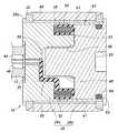
図12及び13は、本発明のダンパ6の第4の実施形態に於けるピストン16の詳細を示す。図12及び13に於いては、前記実施例に対応する部分には同様の符合を付し、その詳しい説明を省略する。 12 and 13 show details of the
インナヨーク26は、軸方向で分割された2つの部分からなり、両部分は、コイル30を埋設した樹脂モールド29を挟持するように互いに衝当している。インナヨーク26の第1の部分26aの衝当面の外周には、軸方向フランジ82が設けられ、該フランジにより、円形の凹部80が画定されている。樹脂モールド29は、凹部80の内周面に沿って配置されている。インナヨーク26の第2の部分26bの衝当面の外周にも、同様の軸方向フランジ82が設けられ、第1の部分26aの軸方向フランジ82との間に磁気的な空隙84が画定されている。第2の部分26bの衝当面の中心には円筒形の突部81が設けられ、樹脂モールド29の内周面に嵌め込まれている。第1の部分26aの衝当面には、更に、樹脂モールド29の直径部分を受容する溝が設けられている。 The
本実施例に於いては、強磁性体からなるアウタヨーク71は、有底筒状をなし、ディスク状のスペーサ85を介して、その底面がインナヨーク26の第1の部分26aのピストンロッド側の面に衝当するように、インナヨーク26に同軸的に嵌装されている。アウタヨーク71の開口端即ち遊端は薄肉部73をなし、インナヨーク26の第2の部分26bの外側軸線方向端面に重合されたディスク状の蓋板72を介して、インナヨーク26の第2の部分26bに対してかしめ付けられている。第2の部分26bの外側軸線方向端面及び蓋板72の対向面の一方には凹部、その他方には、同凹部に突入する補完的な突部が設けられている。 In the present embodiment, the
一方、アウタヨーク71の本体側の底面の中心には、中空ボス74が同軸的に突出し、インナヨーク26の第1の部分26aの中心孔を同軸的に貫通し、かつインナヨーク26の第2の部分26bの中心凹部内に同軸的かつ補完的に嵌入することにより、インナヨーク26が、アウタヨーク71に対して中心位置決めされる。中空ボス74の中心孔内には、樹脂モールド29の直径部分から同軸的に突出するロッド部75が、同軸的かつ補完的に嵌入している。中空ボス74の中心孔の内周面には、環状溝76が設けられ、ロッド部75と中空ボス74の中心孔との間のシールを形成するOリング77が受容されている。前記実施例と同様に、コイル30のリード線44は、樹脂モールド29の直径部分及びロッド部75の内部を経て、ピストンロッド13の内孔46から外部に引き出されている。 On the other hand, at the center of the bottom surface of the
本実施例の場合も、磁気的空隙部84を中心とするインナヨーク26の軸線方向長を、コイルの外周側に於いてLb1+Lb2(但し、Lb1は同部分に於けるインナヨークの一方の部分26aの軸線方向長であり、Lb2は同部分に於けるインナヨークの他方の部分26bの軸線方向長である。)、コイルを通過する部分に於いてLa1+La2(但し、La1はインナヨークの同部分に於ける一方の部分26aの軸線方向長であり、La2はインナヨークの同部分に於ける他方の部分26bの軸線方向長である。)であるとすると、(Lb1+Lb2)<(La1+La2)となる。 Also in this embodiment, the axial length of the
上記したような(Lb1+Lb2)<(La1+La2)なる関係を実現するために様々な形状のインナヨークが可能である。図14から図17には、そのような例が示されている。上記した実施例では、磁気的空隙が、平坦な端面を有する2つの筒状部により画定され、端面間の距離が、コイル30を軸線方向に横切る部分の軸線方向長よりも小さくなるようにされているが、図14の実施形態に於いては、磁気的空隙が、2つの筒状部の互いに対向する同軸的な(インナヨークの中心軸を通過する縦断面に於いて傾斜線により表される)円錐面により画定されている。特に、これらの円錐面は、筒状部の内周側に設けられ、筒状部の外周は、インナヨークの残りの部分と協働して全体的に円筒形の輪郭を画定する。 In order to realize the relationship (Lb1 + Lb2) <(La1 + La2) as described above, various shapes of inner yokes are possible. Such an example is shown in FIGS. In the embodiment described above, the magnetic air gap is defined by two cylindrical portions having flat end faces, and the distance between the end faces is made smaller than the axial length of the portion crossing the
図15の実施形態に於いては、磁気的空隙は、平坦な端面を有する2つの筒状部により画定されるが、コイル30を受容する環状溝の側面即ち環状溝に対して軸線方向に対向する面が円錐面により画定されている。特に、半径方向内方に向けて、環状溝の軸線方向長が漸減するように円錐面の向きが定められている。図16の実施形態は、これと同様であるが、環状溝の側面がそれぞれ1つの円錐面のみによって画定され、互いに対向する平坦な端面が退化して、その幅が0となるような構造である。 In the embodiment of FIG. 15, the magnetic air gap is defined by two cylindrical portions having flat end surfaces, but is axially opposed to the side of the annular groove that receives the
図17の実施形態は、図15の実施形態に類似するが、コイル30を受容する環状溝の側面が、インナヨークの中心軸を通過する縦断面に於いて円弧又はそれに類似する曲線により表されるような構造をなしている。この場合も、半径方向内方に向けて、環状溝の軸線方向長が漸減するように曲線の形状が定められている。 The embodiment of FIG. 17 is similar to the embodiment of FIG. 15, but the side of the annular groove that receives the
以上で具体的実施形態の説明を終えるが、本発明は上記実施形態に限定されることなく幅広く変形実施することができる。例えば、上記実施形態は4輪自動車のリヤサスペンションを構成する減衰力可変式ダンパに本発明を適用したものであるが、本発明は、フロントサスペンション用の減衰力可変式ダンパにも適用できるし、2輪自動車等の減衰力可変ダンパ等にも適用可能である。また、インナヨークに設けられる環状溝或いは軸線方向延出部の形状、寸法及び配置等についても、上記実施形態における例示に限るものではなく、設計や製造上の要請に応じて自由に設定可能である。更に、インナヨークの分割面を、環状溝28の側面に整合させる代わりに、環状溝28の中心と一致させ、インナヨークの両部分を概ね同形とすることもできる。その他、アウタヨークやインナヨークの具体的形状やダンパの具体的構造等についても、本発明の趣旨を逸脱しない範囲であれば適宜変更可能である。 Although the description of the specific embodiment is finished as above, the present invention is not limited to the above embodiment and can be widely modified. For example, in the above embodiment, the present invention is applied to a damping force variable damper that constitutes a rear suspension of a four-wheeled vehicle. However, the present invention can also be applied to a damping force variable damper for a front suspension. It can also be applied to a damping force variable damper for a two-wheeled vehicle or the like. Further, the shape, size, arrangement, and the like of the annular groove or the axially extending portion provided in the inner yoke are not limited to the examples in the above embodiment, and can be freely set according to design and manufacturing requirements . Furthermore, instead of aligning the dividing surface of the inner yoke with the side surface of the
2 トレーリングアーム(車輪側部材)
6 ダンパ
12 シリンダ
13 ピストンロッド
14 上部液室(一側液室)
15 下部液室(他側液室)
16 ピストン
22 ダンパベース(車体側部材)
26 インナヨーク
27 締結ねじ
28 環状溝
30 コイル
31 軸線方向延出部
34 エンドプレート
40、71 アウタヨーク(フラックスリング)
2 Trailing arm (wheel side member)
6
15 Lower liquid chamber (other side liquid chamber)
16
26
Claims (4)
Translated fromJapanese前記ピストンは、
前記ピストンの外周側部分を形成するアウタヨークと、
前記アウタヨークの内側に所定の間隙をもって設置され、当該アウタヨークとの間に前記流路を画成するインナヨークと、
前記インナヨークに保持され、前記磁界の形成に供されるコイルとを備え、
前記コイルが、前記インナヨークの外周に凹設された環状溝内に受容され、かつ前記インナヨークが、前記コイルの外周に向けてオーバハングするように、前記環状溝の外周部側にて軸線方向延出部を有することを特徴とする減衰力可変ダンパ。A cylinder filled with a magnetic fluid or a magnetorheological fluid and connected to one of a vehicle body side member and a wheel side member; and the cylinder is divided into a one side liquid chamber and another side liquid chamber and the magnetic fluid Alternatively, a piston in which a flow path for flowing a magnetorheological fluid between the one-side liquid chamber and the other-side liquid chamber is formed, and a piston that connects the other of the vehicle body-side member and the wheel-side member to the piston. A damping force variable damper, wherein the damping force is controlled by applying a magnetic field to the magnetic fluid or the magnetorheological fluid passing through the flow path,
The piston is
An outer yoke forming an outer peripheral side portion of the piston;
An inner yoke that is installed inside the outer yoke with a predetermined gap, and that defines the flow path between the outer yoke;
A coil held by the inner yoke and used for forming the magnetic field,
The coil is received in an annular groove recessed in the outer periphery of the inner yoke, and the inner yoke extends in the axial direction on the outer peripheral side of the annular groove so as to overhang toward the outer periphery of the coil. Damping force variable damper characterized by having a portion.
前記ピストンは、
前記ピストンの外周側部分を形成するアウタヨークと、
前記アウタヨークの内側に所定の間隙をもって設置され、当該アウタヨークとの間に前記流路を画成するインナヨークと、
前記インナヨークに保持され、前記磁界の形成に供されるコイルとを備え、
前記コイルの外周側に於ける前記インナヨークの軸線方向長が、少なくとも部分的に、前記コイルを通過する前記インナヨークの軸線方向長よりも大きいことを特徴とする減衰力可変ダンパ。A cylinder filled with a magnetic fluid or a magnetorheological fluid and connected to one of a vehicle body side member and a wheel side member; and the cylinder is divided into a one side liquid chamber and another side liquid chamber and the magnetic fluid Alternatively, a piston in which a flow path for flowing a magnetorheological fluid between the one-side liquid chamber and the other-side liquid chamber is formed, and a piston that connects the other of the vehicle body-side member and the wheel-side member to the piston. A damping force variable damper, wherein the damping force is controlled by applying a magnetic field to the magnetic fluid or the magnetorheological fluid passing through the flow path,
The piston is
An outer yoke forming an outer peripheral side portion of the piston;
An inner yoke that is installed inside the outer yoke with a predetermined gap, and that defines the flow path between the outer yoke;
A coil held by the inner yoke and used for forming the magnetic field,
The damping force variable damper, wherein an axial length of the inner yoke on an outer peripheral side of the coil is at least partially larger than an axial length of the inner yoke passing through the coil.
The damping force variable damper according to claim 1 or 3, wherein the inner yoke is composed of at least two parts that are divided in the axial direction and fastened / integrated by a fastening member.
Priority Applications (1)
| Application Number | Priority Date | Filing Date | Title |
|---|---|---|---|
| JP2008062301AJP2009133472A (en) | 2007-10-30 | 2008-03-12 | Variable damping force damper |
Applications Claiming Priority (2)
| Application Number | Priority Date | Filing Date | Title |
|---|---|---|---|
| JP2007281636 | 2007-10-30 | ||
| JP2008062301AJP2009133472A (en) | 2007-10-30 | 2008-03-12 | Variable damping force damper |
Publications (1)
| Publication Number | Publication Date |
|---|---|
| JP2009133472Atrue JP2009133472A (en) | 2009-06-18 |
Family
ID=40865539
Family Applications (1)
| Application Number | Title | Priority Date | Filing Date |
|---|---|---|---|
| JP2008062301APendingJP2009133472A (en) | 2007-10-30 | 2008-03-12 | Variable damping force damper |
Country Status (1)
| Country | Link |
|---|---|
| JP (1) | JP2009133472A (en) |
Cited By (9)
| Publication number | Priority date | Publication date | Assignee | Title |
|---|---|---|---|---|
| JP2009180373A (en)* | 2008-01-29 | 2009-08-13 | Delphi Technologies Inc | Magnetorheological fluid-based device having magnetorheological piston assembly |
| CN102287478A (en)* | 2011-08-25 | 2011-12-21 | 谭晓婧 | Internal-rod plate type magnetorheological damper |
| WO2013129161A1 (en)* | 2012-03-01 | 2013-09-06 | カヤバ工業株式会社 | Magnetic viscous damper |
| WO2013129162A1 (en)* | 2012-03-01 | 2013-09-06 | カヤバ工業株式会社 | Magnetic viscous damper |
| WO2014009000A1 (en)* | 2012-07-09 | 2014-01-16 | Inventus Engineering Gmbh | Method for producing a subassembly and subassembly |
| CN104842737A (en)* | 2014-02-15 | 2015-08-19 | 通用汽车环球科技运作有限责任公司 | Method and apparatus for suspension damping |
| EP2573248A4 (en)* | 2010-05-21 | 2017-11-15 | Toshiba Lifestyle Products & Services Corporation | Damper, washing machine, and washing/drying machine |
| KR101846785B1 (en)* | 2017-07-12 | 2018-04-09 | 주식회사 썬 프레인 코 | Piston structure for MR fluid damper |
| KR102847182B1 (en)* | 2025-01-21 | 2025-08-18 | 김희준 | Shock Absorber with Variable Damping Force |
Citations (1)
| Publication number | Priority date | Publication date | Assignee | Title |
|---|---|---|---|---|
| JP2000514161A (en)* | 1996-07-02 | 2000-10-24 | ロード コーポレーション | Variable vibration device |
- 2008
- 2008-03-12JPJP2008062301Apatent/JP2009133472A/enactivePending
Patent Citations (1)
| Publication number | Priority date | Publication date | Assignee | Title |
|---|---|---|---|---|
| JP2000514161A (en)* | 1996-07-02 | 2000-10-24 | ロード コーポレーション | Variable vibration device |
Cited By (13)
| Publication number | Priority date | Publication date | Assignee | Title |
|---|---|---|---|---|
| US8286763B2 (en)* | 2008-01-29 | 2012-10-16 | Bwi Company Limited S.A. | Magnetorheological fluid-based device having a magnetorheological piston assembly |
| JP2009180373A (en)* | 2008-01-29 | 2009-08-13 | Delphi Technologies Inc | Magnetorheological fluid-based device having magnetorheological piston assembly |
| EP2573248A4 (en)* | 2010-05-21 | 2017-11-15 | Toshiba Lifestyle Products & Services Corporation | Damper, washing machine, and washing/drying machine |
| CN102287478A (en)* | 2011-08-25 | 2011-12-21 | 谭晓婧 | Internal-rod plate type magnetorheological damper |
| US9217486B2 (en) | 2012-03-01 | 2015-12-22 | Kayaba Industry Co., Ltd. | Magnetorheological fluid shock absorber |
| WO2013129161A1 (en)* | 2012-03-01 | 2013-09-06 | カヤバ工業株式会社 | Magnetic viscous damper |
| WO2013129162A1 (en)* | 2012-03-01 | 2013-09-06 | カヤバ工業株式会社 | Magnetic viscous damper |
| JP2013181606A (en)* | 2012-03-01 | 2013-09-12 | Kyb Co Ltd | Magnetorheological fluid damper |
| WO2014009000A1 (en)* | 2012-07-09 | 2014-01-16 | Inventus Engineering Gmbh | Method for producing a subassembly and subassembly |
| US9482304B2 (en) | 2012-07-09 | 2016-11-01 | Inventus Engineering Gmbh | Method for producing a subassembly and subassembly |
| CN104842737A (en)* | 2014-02-15 | 2015-08-19 | 通用汽车环球科技运作有限责任公司 | Method and apparatus for suspension damping |
| KR101846785B1 (en)* | 2017-07-12 | 2018-04-09 | 주식회사 썬 프레인 코 | Piston structure for MR fluid damper |
| KR102847182B1 (en)* | 2025-01-21 | 2025-08-18 | 김희준 | Shock Absorber with Variable Damping Force |
Similar Documents
| Publication | Publication Date | Title |
|---|---|---|
| JP2009133472A (en) | Variable damping force damper | |
| JP2009216210A (en) | Damping force variable damper | |
| US7958979B2 (en) | Variable damper | |
| EP2055985B1 (en) | Magneto-rheological damper | |
| JP5131678B2 (en) | Variable damping force damper | |
| JP5120629B2 (en) | Damping force adjustable shock absorber and suspension control device using the same | |
| US6311810B1 (en) | Magnetorheological fluid damper | |
| EP1437526B1 (en) | Magnetorheological piston and damper assembly | |
| US8770358B2 (en) | Variable damping force damper | |
| JP4500820B2 (en) | Variable damping force damper | |
| US20200263731A1 (en) | Variable stiffness bushing | |
| CN103765036B (en) | Variable damper | |
| JPH10184755A (en) | Variable damping force damper | |
| JP6440861B2 (en) | Shock absorber and method of assembling the shock absorber | |
| JP2020508255A (en) | Chassis parts with rotary damper | |
| JP4654236B2 (en) | Variable damping force damper | |
| JP2008175248A (en) | Damper device | |
| US9103398B2 (en) | Variable damping force damper | |
| JP2009216209A (en) | Damping force variable damper | |
| JP4447018B2 (en) | Variable damping force damper | |
| JPWO2017145983A1 (en) | Damping force adjustable shock absorber | |
| JP4913006B2 (en) | Variable damping force damper | |
| JP2007187176A (en) | Variable damping force damper and vehicle equipped with variable damping force damper | |
| US20240083208A1 (en) | Solenoid, damping force adjustment mechanism, and damping force adjustable shock absorber | |
| JP3016263B2 (en) | Suspension device |
Legal Events
| Date | Code | Title | Description |
|---|---|---|---|
| A621 | Written request for application examination | Free format text:JAPANESE INTERMEDIATE CODE: A621 Effective date:20101125 | |
| RD02 | Notification of acceptance of power of attorney | Free format text:JAPANESE INTERMEDIATE CODE: A7422 Effective date:20110913 | |
| A977 | Report on retrieval | Effective date:20111027 Free format text:JAPANESE INTERMEDIATE CODE: A971007 | |
| A131 | Notification of reasons for refusal | Effective date:20111101 Free format text:JAPANESE INTERMEDIATE CODE: A131 | |
| A02 | Decision of refusal | Free format text:JAPANESE INTERMEDIATE CODE: A02 Effective date:20120228 |