JP2009124644A - Image processing device, imaging device, and image reproduction device - Google Patents
Image processing device, imaging device, and image reproduction deviceDownload PDFInfo
- Publication number
- JP2009124644A JP2009124644AJP2007299205AJP2007299205AJP2009124644AJP 2009124644 AJP2009124644 AJP 2009124644AJP 2007299205 AJP2007299205 AJP 2007299205AJP 2007299205 AJP2007299205 AJP 2007299205AJP 2009124644 AJP2009124644 AJP 2009124644A
- Authority
- JP
- Japan
- Prior art keywords
- image
- image processing
- unit
- displayed
- processing apparatus
- Prior art date
- Legal status (The legal status is an assumption and is not a legal conclusion. Google has not performed a legal analysis and makes no representation as to the accuracy of the status listed.)
- Pending
Links
- 238000012545processingMethods0.000titleclaimsabstractdescription169
- 238000003384imaging methodMethods0.000titleclaimsabstractdescription40
- 238000001514detection methodMethods0.000claimsdescription29
- 238000012937correctionMethods0.000abstractdescription37
- 238000003702image correctionMethods0.000abstractdescription29
- 238000000034methodMethods0.000description33
- 230000006835compressionEffects0.000description18
- 238000007906compressionMethods0.000description18
- 230000008569processEffects0.000description13
- 230000005236sound signalEffects0.000description10
- 238000010586diagramMethods0.000description8
- 238000007781pre-processingMethods0.000description6
- 230000006837decompressionEffects0.000description5
- 230000004048modificationEffects0.000description5
- 238000012986modificationMethods0.000description5
- 238000005034decorationMethods0.000description4
- 230000003287optical effectEffects0.000description4
- 238000006243chemical reactionMethods0.000description3
- 230000000694effectsEffects0.000description3
- 230000006870functionEffects0.000description3
- 238000003672processing methodMethods0.000description3
- 230000008921facial expressionEffects0.000description2
- 230000007274generation of a signal involved in cell-cell signalingEffects0.000description2
- 239000004973liquid crystal related substanceSubstances0.000description2
- 238000000513principal component analysisMethods0.000description2
- 230000003044adaptive effectEffects0.000description1
- 230000008859changeEffects0.000description1
- 230000007423decreaseEffects0.000description1
- 210000005069earsAnatomy0.000description1
- 210000001508eyeAnatomy0.000description1
- 210000004709eyebrowAnatomy0.000description1
- 210000000744eyelidAnatomy0.000description1
- 210000000887faceAnatomy0.000description1
- 230000001815facial effectEffects0.000description1
- 238000013507mappingMethods0.000description1
- 238000005457optimizationMethods0.000description1
- 230000009467reductionEffects0.000description1
- 230000001360synchronised effectEffects0.000description1
Images


Landscapes
- Image Processing (AREA)
- Studio Devices (AREA)
- Image Analysis (AREA)
Abstract
Description
Translated fromJapanese本発明は、画像の補正処理の可能な画像処理装置及び撮像装置に関し、特に複数の条件の補正処理がなされた画像を同時に確認可能なものに関する。 The present invention relates to an image processing apparatus and an imaging apparatus capable of performing image correction processing, and more particularly to an apparatus capable of simultaneously confirming images subjected to correction processing of a plurality of conditions.
現在、デジタルカメラやデジタルビデオカメラのようなデジタル方式の撮像装置が広く普及している。このような撮像装置では、ホワイトバランスや露出補正、シャープネスの補正等の、撮影画像の補正が可能なものが一般的であり、又液晶表示装置等の画像を表示するディスプレイ部を有するため補正した画像をその場で確認できるようになっている。 Currently, digital imaging devices such as digital cameras and digital video cameras are widely used. Such an image pickup apparatus is generally capable of correcting a photographed image such as white balance, exposure correction, and sharpness correction, and is corrected because it has a display unit for displaying an image such as a liquid crystal display device. The image can be checked on the spot.
撮像装置における画像の補正は、従来は設定メニューにおいて適切な補正となるようにパラメータの数値を設定するものである。この方法は、数字とそれによって補正される画質との関係について熟知していないユーザにとっては使いやすいものではない。又、このようなユーザにとって使いやすいものとして、撮像装置のディスプレイ部に表示される補正処理された画像を見ながら補正条件を切り換えて適切な補正条件を選択するものもある。しかし、多くの条件の選択が可能な場合にはそれぞれの条件で補正した画像同士を比較するのは困難である。 Conventionally, the image correction in the imaging apparatus is to set the numerical value of the parameter so as to be an appropriate correction in the setting menu. This method is not easy for a user who is not familiar with the relationship between the number and the image quality corrected thereby. In addition, there is an apparatus that is easy to use for such a user and selects an appropriate correction condition by switching the correction condition while viewing the corrected image displayed on the display unit of the imaging apparatus. However, when many conditions can be selected, it is difficult to compare images corrected under each condition.
そこで引用文献1では、ディスプレイ部の表示領域を分割し、それぞれの分割領域には異なる条件の補正を施した、元の画角のまま縮小した画像を表示する方法が開示されている。この方法によると、異なる条件の補正を施した画像を容易に比較できるため、適切な条件を容易に選択することが可能である。
しかし、撮像装置に設けられたディスプレイ部は大きくないため、引用文献1で提案された方法では、分割領域に表示された画像は小さいものとなる。したがって、撮影者が対象とする被写体(例えば人物の顔)が画像中において比較的小さい場合など、縮小された表示ではその対象とする被写体についての補正状態を比較しにくい場合がある。 However, since the display unit provided in the imaging device is not large, the image displayed in the divided area is small in the method proposed in the cited document 1. Therefore, when the subject (for example, the face of a person) targeted by the photographer is relatively small in the image, it may be difficult to compare the correction states of the subject as a reduced display.
そこで、本発明は画像中における対象とする被写体の大きさが比較的小さい場合でも容易に補正状態を比較することが可能である画像処理装置及び撮像装置を提供することを目的とする。 SUMMARY OF THE INVENTION An object of the present invention is to provide an image processing apparatus and an imaging apparatus that can easily compare correction states even when the size of a subject in the image is relatively small.
上記目的を達成するために、本発明の画像処理装置は、複数の被写体を含む撮像画像に画像処理を施し画像処理部と、前記撮像画像に含まれる被写体のうち特定の被写体を検出する特定被写体検出部と、を備える画像処理装置であって、前記撮像画像の一部に複数の領域を設け、前記複数の領域に前記特定被写体検出部で検出した特定の被写体を拡大したものを表示し、前記複数の領域の各々に異なる条件の画像処理を施すことを特徴とする。 In order to achieve the above object, an image processing apparatus of the present invention performs image processing on a captured image including a plurality of subjects and detects a specific subject from among the subjects included in the captured image. An image processing apparatus comprising a detection unit, wherein a plurality of areas are provided in a part of the captured image, and an enlarged view of a specific subject detected by the specific subject detection unit is displayed in the plurality of regions. Image processing under different conditions is performed on each of the plurality of regions.
又、前記特定の被写体が、事前に前記特定被写体検出部に登録された被写体であってもよく、前記特定の被写体が、人物の顔であっても、動体であってもよい。 Further, the specific subject may be a subject registered in advance in the specific subject detection unit, and the specific subject may be a human face or a moving object.
又、前記特定の被写体が前記撮像画像に複数含まれる場合に、前記特定の被写体の前記撮像画像中での大きさが最も大きいものを前記複数の領域に表示することおしてもよい。 In addition, when a plurality of the specific subjects are included in the captured image, the largest size of the specific subject in the captured image may be displayed in the plurality of regions.
又、前記複数の領域を、前記画像信号の特性値の順に並べることとしてもよい。 The plurality of regions may be arranged in the order of the characteristic values of the image signal.
又、前記複数の領域が前記特定の被写体を拡大したものを分割したものであってもよいし、前記複数の領域の各々が前記特定の被写体を拡大したものであってもよい。 In addition, the plurality of areas may be obtained by dividing an enlargement of the specific subject, or each of the plurality of areas may be an enlargement of the specific subject.
又、本発明の画像処理装置は、撮像画像に画像処理を施す画像処理部を備える画像処理装置であって、前記撮像画像を複数の領域に分割し、各領域に異なる条件の画像処理を施したものを、前記撮像画像中に配置することを特徴とする。 The image processing apparatus of the present invention is an image processing apparatus including an image processing unit that performs image processing on a captured image, and divides the captured image into a plurality of regions, and performs image processing under different conditions on each region. These are arranged in the captured image.
又、本発明の撮像装置は、前記撮像画像を撮像する撮像部と、上述の画像処理装置と、前記画像処理装置で生成した画像処理を施した前記複数の領域を含む画像を表示する表示部と、を備え、前記複数の領域に施される画像処理条件に基づく画像処理を施した前記撮像画像を記録することを特徴とする。 In addition, an imaging apparatus according to the present invention includes an imaging unit that captures the captured image, the above-described image processing device, and a display unit that displays an image including the plurality of regions subjected to image processing generated by the image processing device. And the captured image subjected to image processing based on image processing conditions applied to the plurality of regions is recorded.
又、本発明の画像再生装置は、上述の画像処理装置と、前記画像処理装置で生成した画像処理を施した前記複数の領域を含む画像を表示する表示部と、を備え、前記複数の領域に施される画像処理条件に基づく画像処理を施した前記画像を表示することを特徴とする。 The image reproduction device of the present invention includes the above-described image processing device, and a display unit that displays an image including the plurality of regions subjected to the image processing generated by the image processing device. The image subjected to the image processing based on the image processing condition applied to is displayed.
本発明によると、複数の領域に異なる条件の画像処理を施した画像を表示することができるため、適切な画像処理条件を容易に選択することが可能になる。 According to the present invention, it is possible to display an image that has been subjected to image processing under different conditions in a plurality of regions, so that it is possible to easily select appropriate image processing conditions.
本発明の実施形態について、図面を参照して説明する。尚、以下では、本発明における撮影方法を行うデジタルカメラやデジタルビデオなどの、音声及び映像の記録が可能な撮像装置を例に挙げて説明する。尚、撮像装置は動画及び静止画のうち少なくとも一方の撮影が可能なものであればよい。 Embodiments of the present invention will be described with reference to the drawings. In the following description, an imaging apparatus capable of recording audio and video, such as a digital camera or digital video that performs the imaging method of the present invention, will be described as an example. The imaging device may be any device that can capture at least one of a moving image and a still image.
(撮像装置の構成)
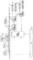
まず、撮像装置の内部構成について、図面を参照して説明する。図1は、本発明の実施形態に係る撮像装置の内部構成を示すブロック図である。(Configuration of imaging device)
First, the internal configuration of the imaging apparatus will be described with reference to the drawings. FIG. 1 is a block diagram illustrating an internal configuration of an imaging apparatus according to an embodiment of the present invention.
図1の撮像装置は、入射される光を電気信号に変換するCCD又はCMOSセンサなどの固体撮像素子(イメージセンサ)1と、被写体の光学像をイメージセンサ1に結像させるズームレンズとズームレンズの焦点距離すなわち光学ズーム倍率を変化させるモータとズームレンズの焦点を被写体に合わせるためのモータとを有するレンズ部2と、イメージセンサ1から出力されるアナログ信号である画像信号をデジタル信号に変換するAFE(Analog Front End)3と、外部から入力された音声を独立して電気信号に変換するマイク4と、AFE3からのデジタル信号となる画像信号に対して、輝度信号及び色差信号の生成を行う前処理及び階調補正や輪郭強調等の各種画像処理を施す画像処理部5と、マイク4からのアナログ信号である音声信号をデジタル信号に変換する音声処理部6と、静止画を撮影する場合は画像処理部5からの画像信号に対してJPEG(Joint Photographic Experts Group)圧縮方式など、動画を撮影する場合は画像処理部5からの画像信号と音声処理部6からの音声信号とに対してMPEG(Moving Picture Experts Group)圧縮方式などの圧縮符号化処理を施す圧縮処理部7と、圧縮処理部7で圧縮符号化された圧縮符号化信号をSDカードなどの外部メモリ22に記録するドライバ部8と、ドライバ部8で外部メモリ22から読み出した圧縮符号化信号を伸長して復号する伸長処理部9と、伸長処理部9で復号されて得られた画像信号をアナログ信号に変換するビデオ出力回路部10と、ビデオ出力回路部10で変換された信号を出力するビデオ出力端子11と、ビデオ出力回路部10からの信号に基づく画像の表示を行うLCD等を有するディスプレイ部12と、伸長処理部9からの音声信号をアナログ信号に変換する音声出力回路部13と、音声出力回路部13で変換された信号を出力する音声出力端子14と、音声出力回路部13からの音声信号に基づいて音声を再生出力するスピーカ部15と、各ブロックの動作タイミングを一致させるためのタイミング制御信号を出力するタイミングジェネレータ(TG)16と、撮像装置内全体の駆動動作を制御するCPU(Central Processing Unit)17と、各動作のための各プログラムを記憶するとともにプログラム実行時のデータの一時保管を行うメモリ18と、静止画撮影用のシャッターボタン、動画撮影用の録画開始ボタン、撮影モードや画像補正条件の選択ボタン等のユーザからの指示が入力される操作部19と、CPU17と各ブロックとの間でデータのやりとりを行うためのバス回線20と、メモリ18と各ブロックとの間でデータのやりとりを行うためのバス回線21と、を備える。 The imaging apparatus of FIG. 1 includes a solid-state imaging device (image sensor) 1 such as a CCD or CMOS sensor that converts incident light into an electrical signal, and a zoom lens and a zoom lens that form an optical image of a subject on the image sensor 1. A
(撮像装置の基本動作 静止画撮影、再生時)
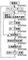
次に、この撮像装置の静止画撮影時の基本動作について図2のフローチャートを用いて説明する。まず、ユーザが撮像装置を静止画撮影用に設定して電源をONにすると(STEP201)、撮像装置の駆動モードつまりイメージセンサ1の駆動モードがプレビューモードに設定される(STEP202)。プレビューモードとは、撮影対象となる画像を記録することなくディスプレイ部12に表示するモードであり、撮影対象を定め、構図を決定するために用いることができる。続いて撮影モードの入力待ち状態となり、人物撮影に適したモードや移動物の撮影に適したモード、逆光での撮影に適したモード等、撮像装置の機能に応じたモードがユーザによって選択される。撮影モードが入力されない場合は通常撮影用のモードが選択されたものとする。同時に、画像補正処理条件の入力待ち状態となり、ホワイトバランスや露出補正等の画像補正条件がユーザによって選択される。画像補正処理条件が入力されない場合は、条件のうちの一つが自動的に選択される(STEP203)。この画像補正条件設定時の動作については後述する。プレビューモードでは、イメージセンサ1の光電変換動作によって得られたアナログ信号である画像信号がAFE3においてデジタル信号に変換されて、画像処理部5で画像処理が施され、圧縮処理部7で圧縮された現時点の画像に対する画像信号が外部メモリ22に一時的に記録される。この圧縮信号は、ドライバ部8を経て、伸長処理部9で伸長され、現時点で設定されているレンズ部2のズーム倍率での画角の画像がディスプレイ部12に表示される。(Basic operation of the imaging device)
Next, the basic operation of the image pickup apparatus at the time of still image shooting will be described with reference to the flowchart of FIG. First, when the user sets the imaging device for still image shooting and turns on the power (STEP 201), the driving mode of the imaging device, that is, the driving mode of the image sensor 1 is set to the preview mode (STEP 202). The preview mode is a mode in which an image to be photographed is displayed on the
続いてユーザが、撮影の対象とする被写体に対して所望の画角となるように、光学ズームでのズーム倍率を設定する(STEP204)。その際、画像処理部5に入力された画像信号を基にCPU17によってレンズ部2を制御して、最適な露光制御(Automatic Exposure;AE)・焦点合わせ制御(オートフォーカス、Auto Focus;AF)が行われる(STEP205)。ユーザが撮影画角、構図を決定し、操作部19のシャッターボタンを半押しすると(STEP206)、AEの調整を行い(STEP207)、AFの最適化処理を行う(STEP208)。 Subsequently, the user sets the zoom magnification with the optical zoom so that the desired angle of view is obtained with respect to the subject to be imaged (STEP 204). At this time, the
その後、シャッターボタンが全押しされると(STEP209)、TG16より、イメージセンサ1、AFE3、画像処理部5及び圧縮処理部7それぞれに対してタイミング制御信号が与えられ、各部の動作タイミングを同期させ、イメージセンサ1の駆動モードを静止画撮影モードに設定する(STEP210)。イメージセンサ1から出力されるアナログ信号である画像信号(生データ)は、AFE3でデジタル信号に変換され、画像処理部5内の前処理部で前処理が施される(STEP211)。前処理とは、各画素位置のRGB成分を算出する色同時化処理、輝度信号生成処理、色信号生成処理等の処理のことである。画像処理部5において、前処理が施された画像信号に対して階調補正や輪郭強調等の各種画像処理が施され、画像処理が施された信号が圧縮処理部7においてJPEG(Joint Photographic Experts Group)形式に圧縮された(STEP212)後、外部メモリ22に圧縮画像を書き込み(STEP213)、撮影を完了する。その後、プレビューモードに戻る(STEP202)。 Thereafter, when the shutter button is fully pressed (STEP 209), the
又、外部メモリ22に記録された静止画像を再生することが、操作部19を通じて指示されると、外部メモリ22に記録された圧縮信号が伸長処理部9において、JPEG圧縮符号方式に基づいて伸長復号されて、画像信号が取得される。そして、画像信号がディスプレイ部12に与えられて画像が再生される。 When the
(撮像装置の基本動作 動画撮影、再生時)
次に、この撮像装置の動画撮影時の基本動作について図3のフローチャートを用いて説明する。まず、ユーザが撮像装置を静止画撮影用に設定して電源をONにすると(STEP301)、撮像装置の駆動モードつまりイメージセンサ1の駆動モードがプレビューモードに設定される(STEP302)。続いて撮影モードの入力待ち状態となる。撮影モードが入力されない場合は通常撮影用のモードが選択されたものとする。同時に、画像補正処理条件の入力待ち状態となり、ホワイトバランスや露出補正等の画像補正条件がユーザによって選択される。画像補正処理条件が入力されない場合は、条件のうちの一つが自動的に選択される(STEP303)。プレビューモードでは、イメージセンサ1の光電変換動作によって得られたアナログ信号である画像信号がAFE3においてデジタル信号に変換されて、画像処理部5で前処理及び画像処理が施され、圧縮処理部7で圧縮された現時点の画像に対する画像信号が外部メモリ22に一時的に記録される。この圧縮信号は、ドライバ部8を経て、伸長処理部9で伸長され、現時点で設定されているレンズ部2のズーム倍率での画角の画像がディスプレイ部12に表示される。ここで、ディスプレイ部12で表示される画像は、後述する画像補正設定動作によって設定される表示をするものであってもよい。(Basic operation of the imaging device)
Next, the basic operation of the imaging apparatus during moving image shooting will be described with reference to the flowchart of FIG. First, when the user sets the imaging apparatus for still image shooting and turns on the power (STEP 301), the driving mode of the imaging apparatus, that is, the driving mode of the image sensor 1 is set to the preview mode (STEP 302). Subsequently, the camera enters a shooting mode input waiting state. When the shooting mode is not input, it is assumed that the normal shooting mode is selected. At the same time, the process waits for input of image correction processing conditions, and image correction conditions such as white balance and exposure correction are selected by the user. If no image correction processing condition is input, one of the conditions is automatically selected (STEP 303). In the preview mode, an image signal that is an analog signal obtained by the photoelectric conversion operation of the image sensor 1 is converted into a digital signal by the
続いてユーザが、撮影の対象とする被写体に対して所望の画角となるように、光学ズームでのズーム倍率を設定する(STEP304)。その際、画像処理部5に入力された画像信号を基にCPU17によってレンズ部2を制御して、最適な露光制御(Automatic Exposure;AE)・焦点合わせ制御(オートフォーカス、Auto Focus;AF)が行われる(STEP305)。 Subsequently, the user sets the zoom magnification with the optical zoom so that the desired angle of view is obtained with respect to the subject to be imaged (STEP 304). At this time, the
その後、操作部19の録画開始ボタン(シャッターボタン兼用でも構わない)が全押しされ、撮像動作を行うことが指示されると(STEP306)、イメージセンサ1の光電変換動作によって得られたアナログ信号である画像信号がAFE3に出力される。このとき、イメージセンサ1では、TG16からのタイミング制御信号が与えられることによって、水平走査及び垂直走査が行われて、画素毎のデータとなる画像信号が出力される。そして、AFE3において、アナログ信号である画像信号(生データ)がデジタル信号に変換されて、画像処理部5内の前処理部で前処理が施される(STEP307)。 Thereafter, when a recording start button (which may be used as a shutter button) of the
画像処理部5で前処理及び画像処理が施された画像信号が圧縮処理部7に与えられる。このとき、マイク4に音声入力されることで得られたアナログ信号である音声信号が、音声処理部6でデジタル信号に変換されて、圧縮処理部7に与えられる。これにより、圧縮処理部7では、デジタル信号である画像信号及び音声信号に対して、MPEG圧縮符号方式に基づいて圧縮符号化し(STEP308)、ドライバ部8に与えて外部メモリ22に記録させる(STEP309)。画像信号及び音声補正制御を施した音声信号と共に、音声補正制御を施していない音声信号とインデックスとしてその信号を取得した時点のズーム倍率情報も記録してもよい。又、このとき、外部メモリ22に記録された圧縮信号がドライバ部8によって読み出されて伸長処理部9に与えられて、伸長処理が施されて画像信号が得られる。この画像信号がディスプレイ部12に与えられて、現在、イメージセンサ1を通じて撮影されている被写体画像が表示される。その後、再び操作部19の録画開始ボタンが全押しされるとプレビューモードに戻る(STEP302)。 The image signal that has been pre-processed and image-processed by the image processing unit 5 is supplied to the
このように撮像動作を行うとき、TG16によって、AFE3、画像処理部5、音声処理部6、圧縮処理部7、及び伸長処理部9に対してタイミング制御信号が与えられ、イメージセンサ1による1フレームごとの撮像動作に同期した動作が行われる。 When the imaging operation is performed in this way, a timing control signal is given to the
又、外部メモリ22に記録された動画を再生することが操作部19を通じて指示されると、外部メモリ22に記録された圧縮信号は、ドライバ部8によって読み出されて伸長処理部9に与えられる。そして、伸長処理部9において、MPEG圧縮符号方式に基づいて、伸長復号されて、画像信号及び音声信号が取得される。そして、画像信号がディスプレイ部12に与えられて画像が再生されるとともに、音声信号が音声出力回路部13を介してスピーカ部15に与えられて音声が再生される。これにより、外部メモリ22に記録された圧縮信号に基づく動画が音声とともに再生される。 In addition, when the
(画像補正条件設定動作)
次に、本実施形態に係る画像補正設定動作について説明する。図4は本実施形態に係る画像補正設定動作時のディスプレイ部に表示される画像の一例である。(Image correction condition setting operation)
Next, an image correction setting operation according to the present embodiment will be described. FIG. 4 is an example of an image displayed on the display unit during the image correction setting operation according to the present embodiment.
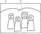
プレビューモードにおいて、撮影者が操作部19で画質設定を指示すると画像補正条件設定モードとなり、図4に示すようにディスプレイ部12に表示されている画像30が縦2列横2行の4個の分割領域に分割され、それぞれに異なる条件の画像補正が施された表示となる。この場合の画像補正としては、ホワイトバランスや露出補正、シャープネスの補正等が挙げられる。ここでは、ホワイトバランスを例に挙げる。尚、ここでは画像30を4個の分割領域に分割した例を示すが、分割領域の数や配置はこの例の場合に限られない。 In the preview mode, when the photographer instructs the image quality setting with the
各分割領域にはそれぞれ異なるホワイトバランス調整が施され、ホワイトバランスの調整条件を示すアイコンが表示される。図4では各分割領域について、左上は太陽、左下は曇の野外、右上は蛍光灯、右下は白熱灯をそれぞれ光源とする場合についてのホワイトバランス調整を施した画像である。 Each divided area is subjected to a different white balance adjustment, and an icon indicating a white balance adjustment condition is displayed. In FIG. 4, for each divided region, the upper left is the sun, the lower left is the cloudy field, the upper right is the fluorescent light, and the lower right is an image subjected to white balance adjustment when the incandescent light is used as the light source.
そして、この異なった種類のホワイトバランス調整が施された画像が表示された状態で、分割領域のうちの1個に表示される枠カーソル31を撮影者が操作部19を操作して所望の調整条件を選択する。枠カーソル31は分割領域の輪郭に表示される四角形の枠であり、操作部19を操作することにより例えば左上から左下、右上、右下、そして再び左上の順に移動する。図4は右上の分割領域が選択されている場合を示す。所望の調整条件を選択した後、操作部19の操作により決定を指示すると選択したホワイトバランス調整が施された元の大きさの画像がディスプレイ部12に表示される。 The photographer operates the
このように構成することにより、各ホワイトバランスの調整条件を比較することができるため、適切なホワイトバランス調整を容易に選択することが可能となる。 By configuring in this way, it is possible to compare the adjustment conditions of the respective white balances, so that it is possible to easily select an appropriate white balance adjustment.
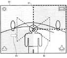
本実施形態において、各画像補正条件の中間の条件に設定したい場合には、操作部191の操作により中間条件設定モードに切り換えて、図5に示すようにディスプレイ部12に補助線32及び矢印で示す矢印カーソル33を表示させる。補助線32は各分割領域の中央を結ぶ線であり、矢印カーソル33は補助線32の一点を指し示す。補正条件は、矢印カーソル33から補助線32の各々の端部までの距離を基準として、矢印カーソル33の位置する補助線32の両端の補正条件を、矢印カーソル33に近いほうの補正条件の割り合が多くなるように配分して合成したものである。そして、矢印カーソル33を移動させることにより各補正条件の中間の条件を選択することが可能となる。矢印カーソル33は、各分割領域を選択する枠カーソル31と同じ方向に移動する。この場合、その補正条件での補正が施された画像は表示しなくてもよいし、何れかの分割領域に表示してもよい。表示する場合には、矢印カーソル33が指している位置が含まれる分割領域に表示してもよいし、矢印カーソル33が指している補助線32の位置が含まれる分割領域の斜め方向にある分割領域に表示してもよい。矢印カーソル33が指している補助線32の位置が含まれる領域の斜め方向にある分割領域に表示した場合、例えば矢印カーソル33が図5に表示されている位置を指している場合には右上の分割領域に、左上と左下の補正条件の中間の条件で補正が施された画像を設定することになり、中間の条件とその両端の補正条件とが比較しやすくなる。 In the present embodiment, when it is desired to set an intermediate condition among the image correction conditions, the operation unit 191 is operated to switch to the intermediate condition setting mode, and the
本実施形態において、特定の被写体を検出し、その被写体を拡大してディスプレイ部12に表示されている画像30の一部に表示し、その拡大した被写体を複数の領域に分割してそれぞれの領域に異なる条件の画像補正を施してもよい。特定の被写体の検出方法については後述する。図6は、画像30の右下に、特定の被写体である人物の顔を拡大した拡大部34を表示した例である。拡大部34では縦2列横2行の4個の分割領域に分割されている。拡大部34のそれぞれの分割領域には異なる条件の画像補正が施され、左上は太陽、左下は曇の野外、右上は蛍光灯、右下は白熱灯をそれぞれ光源とする場合についてのホワイトバランス調整を施している。又、それぞれ分割領域には対応するホワイトバランスの調整条件を示すアイコンを表示する。この場合も、ディスプレイ部12に表示される画像30の全体を分割して表示した場合と同様に、拡大部34の分割領域の1個の輪郭に表示される枠カーソル31又は拡大部34に表示される補助線32と補助線32の一点を指し示す矢印カーソル33で補正条件を選択するようにすればよい。図6では枠カーソル31のみを示し、補助線32及び矢印カーソル33は示していない。尚、この拡大した部分の画像中での大きさ及び位置は任意である。 In the present embodiment, a specific subject is detected, the subject is enlarged and displayed on a part of the
このように、特定の被写体を拡大して表示することによって、例えば人物が画面上で小さく映っている場合には人物の顔色の補正のされ方が比較しやすくなり、適切な補正条件を選択しやすくなる。又、ディスプレイ部12に表示される画像30の全体を分割して表示した場合、図4の様に人物が画像30の中央部に位置している場合にしか顔色の補正条件の比較ができないが、一方、人物の顔を拡大して表示した場合には人物が画像の中央部から外れていても顔色の補正条件を比較することができる。 In this way, by enlarging and displaying a specific subject, for example, when a person appears small on the screen, it is easy to compare how the face color of the person is corrected, and select an appropriate correction condition. It becomes easy. When the
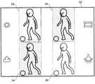
又、本実施形態において、特定の被写体を検出し、その被写体を拡大したものを複数ディスプレイ部12に表示される画像30中に表示し、それぞれの拡大した被写体に異なる条件画像補正を施してもよい。図7は、ディスプレイ部12に、特定の被写体である人物の顔を拡大した拡大部34を縦2列横2行の4個表示した例である。それぞれの拡大部34には異なる画像補正が施され、左上は太陽、左下は曇の野外、右上は蛍光灯、右下は白熱灯をそれぞれ光源とする場合についてのホワイトバランス調整を施している。又、それぞれの拡大部34には対応するホワイトバランスの調整条件を示すアイコンを表示する。この場合も、ディスプレイ部12の全体を分割して表示した場合と同様に、拡大部34の分割領域の1個の輪郭に表示される枠カーソル31又は拡大部34に表示される補助線32と補助線32の一点を指し示す矢印カーソル33で補正条件を選択するようにすればよい。図7では枠カーソル31のみを示し、補助線32及び矢印カーソル33は示していない。尚、ここでは画像30に拡大部34を4個表示した例を示すが、拡大部34の数や配置はこの例の場合に限られない。 In the present embodiment, a specific subject is detected, and an enlarged view of the subject is displayed in the
このように、特定の被写体を拡大したものを複数表示することによって、例えば光の当たり具合や影の出来具合によって顔の部分毎に顔色が大きく異なるような場合にでも顔全体が補正された状態を比較することができるため、適切な補正条件をより選択しやすくなる。 In this way, by displaying a plurality of magnified images of a specific subject, the entire face is corrected even when the face color varies greatly from face part to face part due to, for example, how light strikes or how much shadow is produced Therefore, it is easier to select an appropriate correction condition.
(顔検出処理)
ここで、この撮像装置の、特定の被写体の検出方法の一例として、顔検出処理について説明する。画像処理部5は顔検出装置40を備え、入力された画像信号から人物の顔を検出することができる。顔検出装置40の構成及び動作について以下に説明する。(Face detection process)
Here, face detection processing will be described as an example of a specific subject detection method of the imaging apparatus. The image processing unit 5 includes a
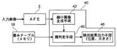
図8は、顔検出装置40の構成を示すブロック図である。顔検出装置40は、AFE3によって得られた画像データに基づいて1又は複数の縮小画像を生成する縮小画像生成手段42、入力画像及び縮小画像から構成される各階層画像とメモリ18に記憶された顔検出用の重みテーブルとを用いて入力画像に顔が存在するか否かを判定する顔判定手段45、及び顔判定手段45の検出結果を出力する検出結果出力手段46を備えている。検出結果出力手段46は、顔が検出された場合には、検出された顔の入力画像を基準とする大きさと位置及び顔の大きさから推定したその顔までの距離を出力する。 FIG. 8 is a block diagram illustrating a configuration of the
又、メモリ18に記憶された重みテーブルは、大量の教師サンプル(顔及び非顔のサンプル画像)から求められたものである。このような重みテーブルは、例えば、Adaboostと呼ばれる公知の学習方法を利用して作成することができる(Yoav Freund, Robert E. Schapire,"A decision-theoretic generalization of on-line learning and an application to boosting", European Conference on Computational Learning Theory, September 20,1995.)。 The weight table stored in the
尚、Adaboostは、適応的なブースティング学習方法の1つで、大量の教師サンプルをもとに、複数の弱識別器候補の中から識別に有効な弱識別器を複数個選択し、それらを重み付けして統合することによって高精度な識別器を実現する学習方法である。ここで、弱識別器とは、全くの偶然よりは識別能力は高いが、十分な精度を満たすほど高精度ではない識別器のことをいう。弱識別器の選択時には、既に選択した弱識別器がある場合、選択済の弱識別器によって誤認識してしまう教師サンプルに対して学習を重点化することによって、残りの弱識別器候補の中から最も効果の高い弱識別器を選択する。 Adaboost is an adaptive boosting learning method. Based on a large number of teacher samples, Adaboost selects multiple weak classifiers that are effective for identification from among a plurality of weak classifier candidates. This is a learning method for realizing a highly accurate classifier by weighting and integrating. Here, a weak classifier refers to a classifier that has a higher discrimination ability than a coincidence but is not high enough to satisfy sufficient accuracy. When a weak classifier is selected, if there is a weak classifier that has already been selected, the learning is focused on the teacher sample that is misrecognized by the selected weak classifier. To select the most effective weak classifier.
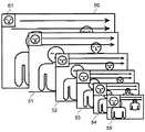
図9は、縮小画像生成手段42によって得られる階層画像の一例を示している。この例では、縮小率を0.8に設定した場合に、生成される複数の階層画像を示している。図9において、50は入力画像を、51〜55は縮小画像を示している。61は判定領域を示している。この例では、判定領域は縦24画素、横24画素の大きさに設定されている。判定領域の大きさは、入力画像及び各縮小画像においても同じである。又、この例では、矢印で示すように、階層画像上で判定領域を左から右に移動させる、水平方向走査を、上方から下方に向かって行うことで、判定領域とマッチングする顔画像の検出を行う。ただし、走査順はこれに限られるものではない。入力画像50の他に、複数の縮小画像51〜55を生成しているのは、1種類の重みテーブルを用いて大きさが異なる顔を検出するためである。 FIG. 9 shows an example of a hierarchical image obtained by the reduced image generating means 42. This example shows a plurality of hierarchical images generated when the reduction ratio is set to 0.8. In FIG. 9, 50 indicates an input image and 51-55 indicate reduced images.
図10は顔検出処理を説明するための図である。顔判定手段45による顔検出処理は、各階層画像について行われるが、処理方法は同様なので、ここでは入力画像50に対して行なわれる顔検出処理についてのみ説明する。図10には、入力画像50と、入力画像内に設定された判定領域61とを示している。 FIG. 10 is a diagram for explaining the face detection process. The face detection process by the
各階層画像について行われる顔検出処理は、画像内に設定された判定領域に対応する画像と重みテーブルとを用いて行なわれる。顔検出処理は粗い判定から順次細かい判定に移行する複数の判定ステップからなり、ある判定ステップにおいて、顔が検出されなかった場合には、次の判定ステップには移行せず、当該判定領域には顔は存在しないと判定する。全ての判定ステップにおいて、顔が検出された場合にのみ、当該判定領域に顔が存在すると判定し、判定領域を走査して次の判定領域での判定に移行する。そして、顔が検出されたとき、いずれの階層画像が用いられていたかによって、入力画像を基準とする顔の大きさ及び顔までの距離を推定することができる。このようにして、検出された顔の位置、大きさ及びその顔を有する人物までの距離は検出結果出力手段46によって出力される。尚、このような顔検出処理については、本願出願人による特許出願である特願2006−053304号に詳しく記載されている。 The face detection process performed for each hierarchical image is performed using an image corresponding to the determination region set in the image and a weight table. The face detection process includes a plurality of determination steps that sequentially shift from a rough determination to a fine determination. When a face is not detected in a certain determination step, the process does not proceed to the next determination step, and the determination area includes It is determined that no face exists. In all the determination steps, only when a face is detected, it is determined that a face exists in the determination area, and the determination area is scanned to shift to determination in the next determination area. When a face is detected, the size of the face and the distance to the face can be estimated based on the input image depending on which layer image is used. Thus, the detection result output means 46 outputs the position and size of the detected face and the distance to the person having the face. Such face detection processing is described in detail in Japanese Patent Application No. 2006-053304, which is a patent application filed by the present applicant.
又、特定の被写体が人物の顔であり、画面内に複数の人物が存在している場合には、顔認識機能を用いて、事前に登録された人物の顔を検出してその顔を拡大して表示してもよい。図11は画面内に複数の人物が存在している場合のプレビュー画像である。対象となる人物の顔には検出されたことを示す枠38が表示される。事前に登録したこの状態で操作部19を操作して画像補正条件の選択を決定することにより、対象となる人物の顔を拡大して表示する。又、事前に登録された人物が複数画面内に存在している場合には、それぞれの人物の顔に枠38を表示し、操作部19でいずれかの枠38を選択するようにしてもよいし、画像30において顔が最も大きく表示されている人物について表示するものとしてもよい。また、画面内に複数の人物が存在しているものの事前に登録された人物が検出されなかった場合は、画像30において顔が最も大きく表示されている人物について表示するものとしてもよい。 If the specific subject is a person's face and there are multiple persons on the screen, the face recognition function is used to detect the face of the person registered in advance and enlarge the face. May be displayed. FIG. 11 is a preview image when there are a plurality of persons on the screen. A
登録された顔を検出する方法としては、例えば主成分分析を用いることができる。主成分分析とは、多変量で表されるデータの統計から一次結合で表現される新たな変量を構成し、互いに無相関な主成分に要約する方法である。この場合、特定の人物の顔の画像データに基づいて画素値と固有ベクトルを算出し、さらに主成分スコア及び写像を導出する。そして、プレビュー画像中から得られた各人物についての写像と、特定の人物についての写像とを比較して最も近い値を持つ人物の顔を同一の人物の顔と認識するものである。 As a method for detecting a registered face, for example, principal component analysis can be used. Principal component analysis is a method of constructing new variables expressed by linear combinations from data statistics expressed in multivariate and summarizing them into uncorrelated principal components. In this case, the pixel value and the eigenvector are calculated based on the image data of the face of a specific person, and the principal component score and mapping are derived. Then, a map of each person obtained from the preview image is compared with a map of a specific person, and the face of the person having the closest value is recognized as the face of the same person.
尚、特定の被写体の検出方法としては、動体追尾を利用してもよい。図12は動体として動き回る人物を含む画像の一例であり、図13はこの動き回る人物を拡大して複数表示した画像の一例である。動体追尾により検出された動いている物体を拡大したものをディスプレイ部12に表示される画像30中に表示する。この場合、動体追尾を利用することで、特定の被写体が動体であっても、撮影者が対象となる動体を撮影する画像から外さない程度に撮影していれば、その動体を自動的に拡大して表示させることができ、画像補正条件を設定することが容易となる。 Note that moving object tracking may be used as a method for detecting a specific subject. FIG. 12 is an example of an image including a person who moves around as a moving object, and FIG. 13 is an example of an image in which a plurality of persons who move around are enlarged and displayed. An enlarged image of a moving object detected by moving object tracking is displayed in an
動体追尾の方法としては、例えばブロックマッチング法を用いることができる。これは、追尾対象を追尾ブロックとして設定し、これに対して追尾を行うものである。この手法について図14を参照して簡単に説明する。 As a moving body tracking method, for example, a block matching method can be used. In this method, a tracking target is set as a tracking block, and tracking is performed on this. This method will be briefly described with reference to FIG.
図14(a)において、符号100は第(n−1)フレーム画像を表し、符号101は第(n−1)フレーム画像における着目した追尾ブロックを表す。図14(b)において、符号110は第nフレーム画像を表し、符号111は第nフレーム画像における着目した候補ブロックを表し、符号112は候補ブロック111が位置しうる探索ブロックを表す。尚、第(n−1)フレーム画像及び第nフレーム画像とは、それぞれ第(n−1)番目のフレームの撮影によって得られたフレーム画像及び第n番目のフレームの撮影によって得られたフレーム画像を指す。 In FIG. 14A,
画像処理部5に設けられた追尾部では、追尾ブロック101と候補ブロック111との間の相関値を算出する。この際、候補ブロック111は、探索ブロック112内で水平方向又は垂直方向に1画素ずつ移動させられ、その移動の度に相関値が算出される。相関値は、例えば、追尾ブロック101と候補ブロック111との間における、各画素の輝度差の絶対値の総和とされる。この相関値は、一般的にSAD(Sum of Absolute Difference)と呼ばれる。相関値として、輝度差の2乗和(Sum of Squared Difference)を用いてもよい。 The tracking unit provided in the image processing unit 5 calculates a correlation value between the tracking
相関値は、追尾ブロック101の画像と候補ブロック111の画像との間の相関が高いほど小さくなる。したがって、相関値が最も小さくなる候補ブロック111の位置を求めれば、追跡ブロック101が、第nフレーム画像内のどこに位置しているかを求めることができると共に、第(n−1)フレーム画像と第nフレーム画像間の追尾ブロック101の動きベクトルが求められる。隣接するフレーム間で動きベクトルを繰り返し求め、動きベクトルに応じて追跡ブロックを逐次移動させることにより、追跡ブロック内に収まる移動物体を追跡することができる。尚、このような動体追尾処理については、本願出願人による特許出願である特願2006−292171号に詳しく記載されている。 The correlation value decreases as the correlation between the image of the
以上、画像補正の設定を、プレビュー画像について設定する場合について説明したが、撮影後の画像を表示している場合において、上述の方法で補正条件を選択するようにしてもよい。この場合、補正した画像で補正する前の画像を置き換えてもよいし、補正する前の画像とともに補正した画像を保存するようにしてもよい。 As described above, the case where the image correction setting is set for the preview image has been described. However, when the image after shooting is displayed, the correction condition may be selected by the above-described method. In this case, the image before correction may be replaced with the corrected image, or the corrected image may be stored together with the image before correction.
又、複数の領域に異なる補正条件が施された画面が表示されている際に、画像処理部5で自動的に良いと判断した設定条件の順に並べ替えたものを表示してもよい。例えば、最も良いと判断したものを左上に配置し、左下、右上、右下の順に劣ると判断したものを配置する。判断基準としては、例えば各領域の平均輝度や色が所定の基準値からどの程度離れているかを用いることができる。特定の被写体が顔である場合には各領域の色が適正な肌色に各領域の色が近いかどうかを用いることができる。 Further, when a screen on which different correction conditions are applied to a plurality of areas is displayed, the screens may be displayed in the order of the setting conditions determined to be automatically good by the image processing unit 5. For example, the one determined to be the best is arranged in the upper left, and the one determined to be inferior in the order of lower left, upper right, and lower right. As a determination criterion, for example, how far the average luminance or color of each region is from a predetermined reference value can be used. When the specific subject is a face, it can be used whether the color of each area is close to the appropriate skin color.
(画像再生装置)
尚、本実施形態において、図1に示すような構成の撮像装置を例に挙げて、本発明における画像処理方法について説明したが、本発明は撮像装置のみに利用されるものとは限られない。例えば、画像処理の可能な液晶ディスプレイやプラズマテレビ等の表示装置や画像処理の可能なDVDプレーヤやビデオデッキ等の再生装置のような、映像の出力が可能な画像再生装置においても、本発明における画像補正条件の設定動作を利用可能である。図15に、本実施形態に係る画像補正条件の設定動作を行う画像処理装置(上述の撮像装置における「画像処理部」に相当)を備えた画像再生装置の一例を示す。(Image playback device)
In the present embodiment, the image processing method according to the present invention has been described using the image pickup apparatus having the configuration shown in FIG. 1 as an example. However, the present invention is not limited to being used only for the image pickup apparatus. . For example, the present invention also applies to an image reproduction apparatus capable of outputting video, such as a display apparatus such as a liquid crystal display capable of image processing or a plasma television, or a reproduction apparatus such as a DVD player or a video deck capable of image processing. An image correction condition setting operation can be used. FIG. 15 shows an example of an image reproduction apparatus including an image processing apparatus (corresponding to an “image processing unit” in the above-described imaging apparatus) that performs an operation for setting image correction conditions according to the present embodiment.
図15に示す画像再生装置は、図1に示す撮像装置と同様に、ドライバ部8、伸長処理部9、ビデオ出力回路部10、ビデオ出力端子11、ディスプレイ部12、音声出力回路部13、音声出力端子14、スピーカ部15、TG16、CPU17、メモリ18、操作部19、及び外部メモリ22を備える。ディスプレイ部12は画像再生装置に内蔵されたものであっても、外付けのものであっても構わない。そして、図1の撮像装置とは異なり、画像処理部5に代えて伸長処理部9で取得した画像信号を処理する画像処理装置5aを備える。画像処理装置5aは、図1の画像処理部5と同様の構成である。外部メモリ22から出力された画像信号に対して、画像処理装置5aにおいて本実施形態に係る画像補正条件の設定動作を行うことができる。 The image reproducing apparatus shown in FIG. 15 is similar to the imaging apparatus shown in FIG. 1 in that the
なお、本発明の実施形態において、図1の画像処理部5及び図15の画像処理装置5aは、ハードウェア、或いは、ハードウェアとソフトウェアの組み合わせによって実現可能である。 In the embodiment of the present invention, the image processing unit 5 in FIG. 1 and the
(変形例)
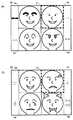
又、本発明における画像処理の変形例について、図16を用いて説明する。図16は図7と同様の図であり、ディスプレイ部12に、被写体である人物の顔を拡大した拡大部34を縦2列横2行の4個表示した例について示したものである。なお、本変形例は、画像の特定部位のみに対して画像処理を行う点において、上述した画像処理例と異なる。(Modification)
A modification of the image processing in the present invention will be described with reference to FIG. FIG. 16 is a diagram similar to FIG. 7, and shows an example in which the
具体的には、上述の画像処理例は、ホワイトバランスや露出補正、シャープネスなどの特に画像全体に効果が反映されるものに対して行うものである。しかしながら、本発明は、図16に示すように画像中の特定部位(例えば、被写体の局部)のみに対して画像処理を行う場合においても適用可能である。以下では、このような特定部位に対してのみ行われる画像処理を局部画像処理として説明するとともに、被写体が人物の顔である場合について説明する。 Specifically, the above-described image processing example is performed on an image whose effect is reflected on the entire image, such as white balance, exposure correction, and sharpness. However, the present invention can also be applied to a case where image processing is performed only on a specific part (for example, a local area of a subject) in an image as shown in FIG. In the following, image processing performed only for such specific parts will be described as local image processing, and a case where the subject is a human face will be described.
図16(a)は、被写体の一部(本例では眉及びまぶた)を変形させる種々の局部画像処理を行った場合を示している。また、図16(b)では、被写体の表情を変化させる局部画像処理や、被写体に飾りを付加する局部画像処理を行った場合について示している。 FIG. 16A shows a case where various local image processes for deforming a part of a subject (in this example, eyebrows and eyelids) are performed. FIG. 16B shows a case where local image processing for changing the facial expression of the subject and local image processing for adding decoration to the subject are performed.
このような局部画像処理を行う場合、被写体の検出には、例えば上述した顔検出や顔認識機能を用いることができる。そして、検出された顔領域を歪ませる(例えば、目元や口元を上げる又は下げる)などの画像処理を行って被写体の表情を変化させたり、検出した顔領域に対して涙や付け耳などの飾りを付加する局部画像処理を施したりするとともに、局部画像処理を施した被写体画像の拡大部34をディスプレイ12に表示する。 When such local image processing is performed, for example, the above-described face detection or face recognition function can be used to detect a subject. Then, image processing such as distorting the detected face area (for example, raising or lowering the eyes or mouth) is performed to change the facial expression of the subject, or decorations such as tears and false ears are detected on the detected face area Local image processing to which the subject image is added, and an
即ち、画像処理を施した被写体画像を拡大してディスプレイ12に表示する点については、上述した画像処理例と同様である。 That is, the subject image that has been subjected to image processing is enlarged and displayed on the
以上のような構成とすることによって、被写体にのみ局部画像処理を施すことができるため、様々な画像を得ることが可能となる。また、局部画像処理が施される被写体を拡大して表示することで、局部画像処理が施された被写体画像を確認することが容易となる。 With the above configuration, local image processing can be performed only on the subject, so that various images can be obtained. Further, by enlarging and displaying the subject on which the local image processing is performed, it becomes easy to check the subject image on which the local image processing has been performed.
なお、複数表示される画像の中に、局部画像処理を施さない画像を含ませてもよい。このような構成とすることで、それぞれの局部画像処理の効果をユーザに明確に認識させることができる。 Note that an image that is not subjected to local image processing may be included in a plurality of displayed images. With such a configuration, the effect of each local image processing can be clearly recognized by the user.
また、ホワイトバランスなどの画像全体に効果が反映される画像処理と、本変形例における局部画像処理と、を組み合わせて処理した画像をディスプレイ12に表示する構成としてもよい。例えば、図6や図7などに示すような全体的な画像処理を施した画像を表示する際に、ある局部画像処理を施した被写体の拡大画像を表示してもよい。このように構成することによって、局部画像処理による違和感が低減される画像処理方法をユーザに確認させ、選択させることが可能となる。 Further, a configuration may be adopted in which an image processed by combining image processing in which the effect is reflected on the entire image such as white balance and local image processing in this modification is displayed on the
また、ユーザによって選択された全体的な画像処理によって補正された画像の画素のパラメータ(例えば、輝度値や色情報など)に基づいて、局部画像処理のパラメータ(例えば、付加する飾りの輝度値や色情報など)を決定するとともに、図16のように種々の局部画像処理を施した画像を表示してもよい。このように構成することによって、局部画像処理によって得られる画像が全体画像に対して馴染むものとなるため、違和感が低減された画像を得ることが可能となる。 Further, based on the pixel parameters of the image (for example, luminance values and color information) corrected by the overall image processing selected by the user, the parameters of the local image processing (for example, the luminance value of the decoration to be added, Color information, etc.) may be determined, and an image subjected to various local image processing may be displayed as shown in FIG. With this configuration, an image obtained by local image processing becomes familiar with the entire image, and thus an image with a reduced sense of discomfort can be obtained.
また、上述した局部画像処理は、画像を歪ませたり飾りを付加したりする画像処理に限られない。例えば、特定部位の輝度や色情報を変化させたりする画像処理などであってもよい。また、上述した動体追尾を利用して動体を検出するとともに拡大して表示し、その動体に対して局部画像処理を行うこととしてもよい。 The local image processing described above is not limited to image processing that distorts an image or adds decorations. For example, image processing that changes the luminance or color information of a specific part may be used. Alternatively, the moving object tracking described above may be used to detect and enlarge the moving object, and local image processing may be performed on the moving object.
以上、本発明における画像処理装置や撮像装置、画像再生装置の実施形態について説明したが、本発明の範囲はこれに限定されるものではなく、発明の主旨を逸脱しない範囲で種々の変更を加えて実行することができる。 The embodiments of the image processing apparatus, the imaging apparatus, and the image reproduction apparatus according to the present invention have been described above. However, the scope of the present invention is not limited to this, and various modifications can be made without departing from the spirit of the invention. Can be executed.
本発明は、画質補正処理を行う画像処理装置、撮像装置及び画像再生装置に適用することができる。 The present invention can be applied to an image processing apparatus, an imaging apparatus, and an image reproduction apparatus that perform image quality correction processing.
1 イメージセンサ
2 レンズ部
3 AFE
4 マイク
5 画像処理部
5a 画像処理装置
6 音声処理部
7 圧縮処理部
8 ドライバ部
9 伸長処理部
10 ビデオ出力回路部
11 ビデオ出力端子
12 ディスプレイ部
13 音声出力回路部
14 音声出力端子
15 スピーカ部
16 タイミングジェネレータ(TG)
17 CPU
18 メモリ
19 操作部
20 バス回線
21 バス回線
22 外部メモリ
30 画像
31 枠カーソル
32 補助線
33 矢印カーソル
34 拡大部
38 枠
40 顔検出装置
42 縮小画像生成手段
45 顔判定手段
46 検出結果出力手段
50 入力画像
51 縮小画像
52 縮小画像
53 縮小画像
54 縮小画像
55 縮小画像
61 判定領域DESCRIPTION OF SYMBOLS 1
4 microphone 5
17 CPU
DESCRIPTION OF
Claims (11)
Translated fromJapanese前記撮像画像の一部に複数の領域を設け、前記複数の領域に前記特定被写体検出部で検出した特定の被写体を拡大したものを表示し、前記複数の領域の各々に異なる条件の画像処理を施すことを特徴とする画像処理装置。An image processing apparatus comprising: an image processing unit that performs image processing on a captured image including a plurality of subjects; and a specific subject detection unit that detects a specific subject among subjects included in the captured image.
A plurality of areas are provided in a part of the captured image, an enlarged view of the specific subject detected by the specific subject detection unit is displayed in the plurality of areas, and image processing under different conditions is performed on each of the plurality of areas. An image processing apparatus.
前記撮像画像を複数の領域に分割し、各領域に異なる条件の画像処理を施したものを、前記撮像画像中に配置することを特徴とする画像処理装置。An image processing apparatus including an image processing unit that performs image processing on a captured image,
An image processing apparatus, wherein the captured image is divided into a plurality of regions, and each region subjected to image processing under different conditions is arranged in the captured image.
請求項1〜9のいずれかに記載の画像処理装置と、
前記画像処理装置で生成した画像処理を施した前記複数の領域を含む画像を表示する表示部と、
を備え、前記複数の領域に施される画像処理条件に基づく画像処理を施した前記撮像画像を記録することを特徴とする撮像装置。An imaging unit that captures the captured image;
An image processing device according to any one of claims 1 to 9,
A display unit for displaying an image including the plurality of regions subjected to image processing generated by the image processing device;
And an image processing apparatus that records the captured image subjected to image processing based on image processing conditions applied to the plurality of regions.
前記画像処理装置で生成した画像処理を施した前記複数の領域を含む画像を表示する表示部と、
を備え、前記複数の領域に施される画像処理条件に基づく画像処理を施した前記撮像画像を表示することを特徴とする画像再生装置。An image processing device according to any one of claims 1 to 9,
A display unit for displaying an image including the plurality of regions subjected to image processing generated by the image processing device;
And displaying the captured image that has been subjected to image processing based on image processing conditions applied to the plurality of regions.
Priority Applications (1)
| Application Number | Priority Date | Filing Date | Title |
|---|---|---|---|
| JP2007299205AJP2009124644A (en) | 2007-11-19 | 2007-11-19 | Image processing device, imaging device, and image reproduction device |
Applications Claiming Priority (1)
| Application Number | Priority Date | Filing Date | Title |
|---|---|---|---|
| JP2007299205AJP2009124644A (en) | 2007-11-19 | 2007-11-19 | Image processing device, imaging device, and image reproduction device |
Publications (1)
| Publication Number | Publication Date |
|---|---|
| JP2009124644Atrue JP2009124644A (en) | 2009-06-04 |
Family
ID=40816272
Family Applications (1)
| Application Number | Title | Priority Date | Filing Date |
|---|---|---|---|
| JP2007299205APendingJP2009124644A (en) | 2007-11-19 | 2007-11-19 | Image processing device, imaging device, and image reproduction device |
Country Status (1)
| Country | Link |
|---|---|
| JP (1) | JP2009124644A (en) |
Cited By (8)
| Publication number | Priority date | Publication date | Assignee | Title |
|---|---|---|---|---|
| JP2011015092A (en)* | 2009-06-30 | 2011-01-20 | Canon Inc | Imaging device |
| JP2011055066A (en)* | 2009-08-31 | 2011-03-17 | Casio Computer Co Ltd | Image capturing apparatus, imaging control program and imaging control method |
| JP2011119809A (en)* | 2009-12-01 | 2011-06-16 | Nec Corp | Imaging apparatus, method and program |
| KR101665130B1 (en) | 2009-07-15 | 2016-10-25 | 삼성전자주식회사 | Apparatus and method for generating image including a plurality of persons |
| GB2553407A (en)* | 2016-06-17 | 2018-03-07 | Canon Kk | Display apparatus and display control method for displaying images |
| JP2019045938A (en)* | 2017-08-30 | 2019-03-22 | オムロン株式会社 | Image processing device, setting support method, and setting support program |
| CN111310567A (en)* | 2020-01-16 | 2020-06-19 | 中国建设银行股份有限公司 | Face recognition method and device under multi-person scene |
| CN116249933A (en)* | 2020-09-30 | 2023-06-09 | 富士胶片株式会社 | Image pickup apparatus, image processing method, and image processing program |
- 2007
- 2007-11-19JPJP2007299205Apatent/JP2009124644A/enactivePending
Cited By (11)
| Publication number | Priority date | Publication date | Assignee | Title |
|---|---|---|---|---|
| JP2011015092A (en)* | 2009-06-30 | 2011-01-20 | Canon Inc | Imaging device |
| KR101665130B1 (en) | 2009-07-15 | 2016-10-25 | 삼성전자주식회사 | Apparatus and method for generating image including a plurality of persons |
| JP2011055066A (en)* | 2009-08-31 | 2011-03-17 | Casio Computer Co Ltd | Image capturing apparatus, imaging control program and imaging control method |
| JP2011119809A (en)* | 2009-12-01 | 2011-06-16 | Nec Corp | Imaging apparatus, method and program |
| GB2553407A (en)* | 2016-06-17 | 2018-03-07 | Canon Kk | Display apparatus and display control method for displaying images |
| US10528792B2 (en) | 2016-06-17 | 2020-01-07 | Canon Kabushiki Kaisha | Display apparatus and display control method for simultaneously displaying a plurality of images |
| GB2553407B (en)* | 2016-06-17 | 2020-01-15 | Canon Kk | Display apparatus and display control method for displaying images |
| JP2019045938A (en)* | 2017-08-30 | 2019-03-22 | オムロン株式会社 | Image processing device, setting support method, and setting support program |
| CN111310567A (en)* | 2020-01-16 | 2020-06-19 | 中国建设银行股份有限公司 | Face recognition method and device under multi-person scene |
| CN111310567B (en)* | 2020-01-16 | 2023-06-23 | 中国建设银行股份有限公司 | Face recognition method and device in multi-person scene |
| CN116249933A (en)* | 2020-09-30 | 2023-06-09 | 富士胶片株式会社 | Image pickup apparatus, image processing method, and image processing program |
Similar Documents
| Publication | Publication Date | Title |
|---|---|---|
| JP4804398B2 (en) | Imaging apparatus and imaging method | |
| US9495578B2 (en) | Face detection device, imaging apparatus and face detection method | |
| US8897501B2 (en) | Face detection device, imaging apparatus, and face detection method | |
| JP5202211B2 (en) | Image processing apparatus and electronic apparatus | |
| JP5084696B2 (en) | Image processing apparatus, image processing method, and electronic apparatus | |
| US20110193986A1 (en) | Image sensing device | |
| JP4286292B2 (en) | Electronic camera | |
| JP2008109336A (en) | Image processing apparatus and imaging apparatus | |
| JP4732303B2 (en) | Imaging device | |
| JP4839908B2 (en) | Imaging apparatus, automatic focus adjustment method, and program | |
| JP2008294785A (en) | Image processor, imaging apparatus, image file, and image processing method | |
| JP2010103972A (en) | Image processing device and electronic appliance | |
| JP4974812B2 (en) | Electronic camera | |
| JP2009124644A (en) | Image processing device, imaging device, and image reproduction device | |
| US20070211161A1 (en) | Electronic camera | |
| US8988545B2 (en) | Digital photographing apparatus and method of controlling the same | |
| JP2009065587A (en) | Voice-recording device and voice-reproducing device | |
| JP2009010616A (en) | Imaging apparatus and image output control method | |
| JP2010028608A (en) | Image processor, image sensing device, reproducer and method for processing image | |
| JP4934617B2 (en) | Imaging apparatus and imaging method | |
| KR20160137289A (en) | Photographing apparatus and method for controlling the same | |
| JP5267279B2 (en) | Image composition apparatus and program | |
| JP2008172395A (en) | Imaging apparatus and image processing apparatus, method, and program | |
| JP4806470B2 (en) | Imaging device | |
| JP4806471B2 (en) | Imaging device |