JP2009122840A - Image data generator - Google Patents
Image data generatorDownload PDFInfo
- Publication number
- JP2009122840A JP2009122840AJP2007294431AJP2007294431AJP2009122840AJP 2009122840 AJP2009122840 AJP 2009122840AJP 2007294431 AJP2007294431 AJP 2007294431AJP 2007294431 AJP2007294431 AJP 2007294431AJP 2009122840 AJP2009122840 AJP 2009122840A
- Authority
- JP
- Japan
- Prior art keywords
- gaze
- image data
- image
- unit
- instruction
- Prior art date
- Legal status (The legal status is an assumption and is not a legal conclusion. Google has not performed a legal analysis and makes no representation as to the accuracy of the status listed.)
- Granted
Links
Images


Landscapes
- Controls And Circuits For Display Device (AREA)
- Processing Or Creating Images (AREA)
- Editing Of Facsimile Originals (AREA)
Abstract
Translated fromJapaneseDescription
Translated fromJapanese本発明は、オペレータが画像を操作する際に用いられる画像データ生成装置に関する。 The present invention relates to an image data generation device used when an operator operates an image.
従来、オペレータが画像を操作することによって、観察者に対してプレゼンテーションを行うためにプレゼンテーションシステムが用いられている(特許文献1参照)。
しかしながら、特許文献1に記載の技術を用いてプレゼンテーションを行う際には、オペレータが指示棒等を用いて画像上を指示してプレゼンテーションの主要部分(注視部)を指示し続けていないと、観察者の関心がオペレータの意図するプレゼンテーションの主要部分以外に向いてしまい、また、オペレータが画像変更をする場合に操作用GUIを表示すると、この操作用GUIに関心が集まってしまい、好適なプレゼンテーションが行われないおそれがあった。 However, when a presentation is performed using the technique described in Patent Document 1, observation is performed unless an operator continues to instruct the main part (gaze portion) of the presentation by pointing on the image using a pointer or the like. If the operator's interest is directed to a part other than the main part of the presentation intended by the operator, and the operator GUI is displayed when the operator changes the image, the operator GUI is interested in the operation GUI. There was a risk of not being done.
本発明は、前記した問題を解決すべく創案されたものであり、観察者の関心を注視部に集め、好適なプレゼンテーションを可能とする画像データ生成装置を提供することを課題とする。 The present invention has been developed to solve the above-described problems, and an object of the present invention is to provide an image data generation apparatus that can gather a viewer's interest in a gaze unit and enable a suitable presentation.
前記課題を解決するため、本発明は、オペレータが画像を操作する際に、表示装置に画像を表示させるための画像データを生成する画像データ生成装置であって、観察者に注視させる注視部と、前記観察者が前記注視部を注視したときの周辺視野領域に設けられた非注視部と、を備える画像を表示させるための画像データを生成する画像データ生成部と、前記オペレータによる操作に基づく指示を取得する指示取得部と、を備え、前記画像データ生成部は、前記指示に基づいて、前記画像の非注視部に対して、当該非注視部の画像が前記注視部の画像よりも注視しにくくなる非注視処理を施すように画像データを処理する非注視処理部を備え、前記指示が取得された場合には、前記画像データ生成部は、非注視処理が施された前記画像データを前記表示装置に出力することを特徴とする。 In order to solve the above-described problem, the present invention provides an image data generation device that generates image data for displaying an image on a display device when an operator operates the image, and a gaze unit that causes an observer to gaze An image data generation unit that generates image data for displaying an image, and a non-gaze unit provided in a peripheral visual field region when the observer gazes at the gaze unit, and based on an operation by the operator An instruction acquisition unit that acquires an instruction, and the image data generation unit gazes the non-gaze part of the image with respect to the non-gaze part of the image based on the instruction. A non-gaze processing unit that processes image data so as to perform non-gaze processing that is difficult to perform, and when the instruction is acquired, the image data generation unit performs the non-gaze processing on the image data And outputs to the display device.
かかる構成によると、非注視部に非注視処理が施されるので、観察者の関心を注視部に集めることができる。 According to such a configuration, since the non-gaze process is performed on the non-gaze part, the observer's interest can be collected on the gaze part.
また、前記課題を解決するため、本発明は、オペレータが画像を操作する際に、表示装置に画像を表示させるための画像データを生成する画像データ生成装置であって、観察者に注視させる注視部と、前記観察者が前記注視部を注視したときの周辺視野領域に設けられた非注視部と、を備える画像を表示させるための画像データを生成する画像データ生成部と、前記オペレータによる操作に基づく指示を取得する指示取得部と、を備え、前記画像データ生成部は、前記指示に基づいて、前記画像の前記注視部に対して、前記非注視部の画像よりも当該注視部の画像に前記観察者を注視させる注視処理を施すように画像データを処理する注視処理部を備え、前記指示が取得された場合には、前記画像データ生成部は、注視処理が施された前記画像データを前記表示装置に出力することを特徴とする。 In order to solve the above-described problem, the present invention provides an image data generation device that generates image data for displaying an image on a display device when an operator operates the image. An image data generation unit for generating image data for displaying an image, and an operation performed by the operator, and a non-gaze unit provided in a peripheral visual field region when the observer gazes at the gaze unit An instruction acquisition unit that acquires an instruction based on the image, and the image data generation unit is configured to generate an image of the gaze unit with respect to the gaze unit of the image rather than the image of the non-gaze unit based on the instruction. A gaze processing unit that processes image data so as to perform a gaze process that gazes the observer, and when the instruction is acquired, the image data generation unit is configured to display the image on which the gaze process has been performed. And outputs the data to the display device.
かかる構成によると、注視部に注視処理が施されるので、観察者の関心を非注視部からそらすことができる。 According to this configuration, since the gaze process is performed on the gaze unit, the observer's interest can be diverted from the non-gaze unit.
また、前記課題を解決するため、本発明は、オペレータが画像を操作する際に、表示装置に画像を表示させるための画像データを生成する画像データ生成装置であって、観察者に注視させる注視部と、前記観察者が前記注視部を注視したときの周辺視野領域に設けられた非注視部と、を備える画像を表示させるための画像データを生成して前記表示装置に出力する画像データ生成部と、前記オペレータによる操作に基づく指示を取得する指示取得部と、を備え、前記画像データ生成部は、前記指示に基づいて、前記画像の非注視部に操作用GUIを表示するように画像データを処理する操作用GUI処理部を備え、前記指示が取得された場合には、前記画像データ生成部は、操作用GUIを表示するように処理された前記画像データを前記表示装置に出力することを特徴とする。 In order to solve the above-described problem, the present invention provides an image data generation device that generates image data for displaying an image on a display device when an operator operates the image. Image data generation for generating and outputting to the display device image data for displaying an image comprising a non-gaze portion provided in a peripheral visual field region when the observer gazes at the gaze unit And an instruction acquisition unit that acquires an instruction based on an operation by the operator, and the image data generation unit displays an operation GUI on a non-gazing unit of the image based on the instruction. An operation GUI processing unit for processing data; and when the instruction is acquired, the image data generation unit displays the image data processed to display the operation GUI as the table. And outputs to the device.
かかる構成によると、操作用GUIを注視部ではなく非注視部に表示するので、観察者に操作用GUIを注視させることなく、注視部であるプレゼンテーションの主要部分を注視させることができる。 According to such a configuration, the operation GUI is displayed on the non-gaze unit, not the gaze unit, so that the main part of the presentation that is the gaze unit can be gazeed without causing the observer to gaze at the operation GUI.
本発明によれば、観察者の関心を注視部に集めることができ、好適なプレゼンテーションを可能とすることができる。 According to the present invention, the viewer's interest can be collected in the gaze unit, and a suitable presentation can be made possible.
以下、本発明の実施形態について、適宜図面を参照しながら説明する。同様の部分には同一符号を付し、重複する説明を省略する。 Hereinafter, embodiments of the present invention will be described with reference to the drawings as appropriate. Similar parts are denoted by the same reference numerals, and redundant description is omitted.
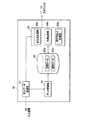
まず、本発明の実施形態に係る画像データ生成装置が適用された画像表示システムの構成について、図1及び図2を参照して説明する。図1は、本発明の実施形態に係る画像表示システムの外観を示す模式図である。図2は、本発明の実施形態に係る画像データ生成装置を示すブロック図である。 First, a configuration of an image display system to which an image data generation device according to an embodiment of the present invention is applied will be described with reference to FIGS. 1 and 2. FIG. 1 is a schematic diagram showing an appearance of an image display system according to an embodiment of the present invention. FIG. 2 is a block diagram showing an image data generation apparatus according to the embodiment of the present invention.
図1に示すように、本発明の実施形態に係る画像表示システムは、オペレータP1が画像を操作することによって、観察者P2に対してプレゼンテーションを行うためのシステムである。本発明におけるプレゼンテーションは、オペレータP1が画像を用いて観察者P2との間で合意を形成するインタラクティブ体験を含む概念である。図1に示すように、本発明の実施形態に係る画像表示システムは、表示装置10と、入力装置20と、画像データ生成装置30と、を備える。 As shown in FIG. 1, the image display system according to the embodiment of the present invention is a system for giving a presentation to an observer P2 by an operator P1 operating an image. The presentation in the present invention is a concept including an interactive experience in which the operator P1 forms an agreement with the observer P2 using an image. As shown in FIG. 1, the image display system according to the embodiment of the present invention includes a
表示装置10は、リアプロジェクション型の装置であり、立体プロジェクタを構成する一対のプロジェクタ11,12と、スクリーン13と、を備える。
一対のプロジェクタ11,12は、画像データ生成装置30から出力された画像データに基づいて、スクリーン13に対してその背面側から画像光を照射する。
スクリーン13は、照射された画像光によって、オペレータP1及び観察者P2に対して三次元の画像を表示する。観察者P2は、スクリーン13から所定の距離だけ又はそれ以上離れて画像を見る。観察者P2とスクリーン13との距離は、後記する非注視部が観察者P2の周辺視野領域に位置するように設定される。The
The pair of
The
なお、表示装置10は、フロントプロジェクション型であり、一対のプロジェクタ11,12がスクリーン13の表面側に設けられていてもよい。
時分割シャッタ方式の立体視を行う場合には、一対のプロジェクタ11,12に代えて設けられた一台の時分割対応プロジェクタ(図示せず)が、観察者P2が装着する液晶シャッタメガネ(図示せず)と同期して右眼用画像光と左眼用画像光とを交互に照射する。
また、偏光方式の立体視を行う場合には、一対のプロジェクタ11,12は、それぞれ右眼用画像光及び左眼用画像光を照射する。一対のプロジェクタ11,12は、互いに直交する偏光(直線偏光または円偏光)板を通して右眼用画像光と左眼用画像光をそれぞれ照射する。観察者P2は、左右が互いに直交する偏光メガネ(図示せず)を装着して3次元の画像を観察する。
なお、立体視をせずに3次元画像を表示する場合には、一対のプロジェクタ11,12及びスクリーン13に代えて、液晶ディスプレイ、プラズマディスプレイ等を使用することができる。
また、立体視対応のディスプレイを使用することもできる。The
When performing time-division shutter-type stereoscopic viewing, a single time-division-compatible projector (not shown) provided in place of the pair of
In addition, when performing polarization-type stereoscopic viewing, the pair of
When displaying a three-dimensional image without stereoscopic viewing, a liquid crystal display, a plasma display, or the like can be used instead of the pair of
A stereoscopic display can also be used.
図1に示すように、入力装置20は、オペレータP1の操作入力に基づいて3次元位置データ(3次元座標)を生成するための3次元位置センサである。また、入力装置20は、オペレータP1の操作入力に基づいて指示データを生成する。3次元位置センサ20としては、磁気式、力学式、ワイヤー式、光学式、超音波式、これらを組み合わせた方式などのセンサが使用可能である。
生成された3次元位置データ及び指示データは、画像データ生成装置30に出力される。As shown in FIG. 1, the
The generated three-dimensional position data and instruction data are output to the image
画像データ生成装置30は、例えば、CPU、RAM、ROM、ディスク等の外部記憶装置および入出力回路を備えており、3次元位置センサ20からの入力と、記憶装置に記憶されたプログラムやデータに基づいて各演算処理を行うことによって、制御を実行する。図2に示すように、画像データ生成装置30は、指示データ取得部31と、データ更新部32と、データ記憶部33と、画像データ生成部34と、を備える。 The image
指示データ取得部31は、入力装置20から入力された3次元位置データ及び指示データを取得する。取得された3次元位置データ及び指示データは、データ更新部32及び画像データ生成部34に出力される。 The instruction
データ更新部32は、入力装置20からの3次元位置データ及び指示データに基づいて、データ記憶部33に記憶された空間データ及び物体データを更新する。また、データ更新部32は、図示しないキーボード等の入力装置からの入力信号に基づいて、新たな物体データを生成してデータ記憶部33に記憶させることができる。 The
データ記憶部33は、画像として表示される空間に関する空間データ33aと、この空間内に配置される物体に関する物体データ33bと、を記憶している。
空間データ33aは、物体が配置される空間に関するデータであり、例えば、住居の一室(床、壁、天井など)の形状、寸法、座標、都市部の一区画(道路、川など)の形状、寸法、座標に関するデータである。
物体データ33bは、物体のID、種類、形状、寸法、座標(位置)、向きなどを関連付けたものである。物体データ33bの移動可能な範囲は、空間データ33aの規定する範囲内である。The
The
The
画像データ生成部34は、データ記憶部33に記憶された空間データ33a及び物体データ33bに基づいて、画像データを生成する。画像データは、観察者P2に注視させる注視部と、観察者P2が注視部を注視したときの周辺視野領域に設けられた非注視部と、を備える画像を表示させるためのデータである。本実施形態において、画像が表示されるスクリーン13は、観察者P2が所定の位置で注視部を注視したときの中心視野よりも大きい画像を表示することが可能な大型スクリーンであり、注視部は、画像の中心部分に設けられ、非注視部は、観察者P2が注視部を注視したときの周辺視野領域に位置する画像の周縁部分に設けられる。
ここで、「中心視野」領域は、視線(注視点)を中心にした約20度の範囲のことであり、観察者は、中心視野領域において物の形を細部にわたって判別したり色を認識したりすることができる。
また、「周辺視野」領域は、中心視野領域から外れた上下130度、左右180度の範囲のことであり、周辺視野領域では、観察者は、当該領域を見てはいるが物の形はぼんやりして、色もあまりわからない。非注視部は、この周辺視野領域に設けられる。
画像データ生成部34は、非注視処理部34aと、注視処理部34bと、操作用GUI処理部34cと、を備える。The image
Here, the “central visual field” region is a range of about 20 degrees centered on the line of sight (gaze point), and the observer can discriminate the shape of the object in detail and recognize the color in the central visual field region. Can be.
In addition, the “peripheral visual field” region is a range of 130 degrees up and down and 180 degrees left and right outside the central visual field region. In the peripheral visual field region, the observer looks at the region but the shape of the object is I don't know much about the color. The non-gaze portion is provided in this peripheral visual field region.
The image
非注視処理部34aは、指示データ取得部31からの指示データに基づいて、画像の非注視部に対して、当該非注視部の画像が注視部の画像よりも注視しにくくなる非注視処理を施すように画像データを処理する。非注視処理は、ぼかし、輝度の低下、コントラストの低下、FOG化及び無彩色化の少なくとも一つを含む。
「ぼかし」は、画像のピクセル単位で周囲の数ピクセルに分配する処理、すなわち、解像度を低下させる処理である。
「輝度の低下」は、画像のピクセル単位でRGB値を所定の割合で減少させる処理である。
「コントラストの低下」は、画像のピクセル単位でRGB値を所定の値に近づけ、RGB値の範囲を限定する処理である。
「FOG化」は、画像のピクセル単位で背景色(例えば、グレー)と元のRGB値とを混合する処理である。
「無彩色化」は、画像のピクセル単位でRGB値を平均化し、モノトーン化する処理である。Based on the instruction data from the instruction
“Blur” is a process of distributing the image to several surrounding pixels, that is, a process of reducing the resolution.
“Brightness reduction” is a process of reducing the RGB value at a predetermined rate in pixel units of the image.
The “decrease in contrast” is a process that limits the RGB value range by bringing the RGB value closer to a predetermined value for each pixel of the image.
“FOG conversion” is a process of mixing a background color (for example, gray) and an original RGB value in pixel units of an image.
“Naturalization” is a process of averaging RGB values in units of pixels of an image and making them monotone.
注視処理部34bは、指示データ取得部31からの指示データに基づいて、非注視部の画像よりも注視部に観察者を注視させる注視処理を施すように画像データを処理する。注視処理は、色の変化、点滅及びアニメーションの表示の少なくとも一つを含む。
「色の変化」は、注視部のプレゼンテーション対象物の色を変化させる処理である。
「点滅」は、注視部のプレゼンテーション対象物を点滅させる処理である。
「アニメーションの表示」は、注視部のプレゼンテーション対象物の近傍にアニメーションを表示させる処理である。Based on the instruction data from the instruction
“Color change” is a process of changing the color of the presentation object of the gaze unit.
“Blinking” is a process of blinking the presentation object of the gaze unit.
“Display animation” is a process of displaying an animation in the vicinity of the presentation object of the gaze unit.
操作用GUI処理部34cは、指示データ取得部31からの指示データに基づいて、画像の非注視部に操作用GUIを表示するように画像データを処理する。 Based on the instruction data from the instruction
すなわち、画像データ生成部34は、指示データが取得された場合には、非注視処理、注視処理及び操作用GUI処理が施された画像データを一対のプロジェクタ11,12に出力する。 That is, when the instruction data is acquired, the image
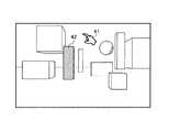
続いて、画像表示システムの動作例について、図3〜図6を参照して説明する。図3〜図6は、本発明の実施形態に係る画像表示システムの動作例を説明するための画像を示す図である。 Subsequently, an operation example of the image display system will be described with reference to FIGS. 3 to 6 are diagrams illustrating images for explaining an operation example of the image display system according to the embodiment of the present invention.
まず、図3(a)に示すように、スクリーン13に、画像データ生成装置30の画像データ生成部34によって生成・出力された画像データによる画像が表示されている。
この画像において、カーソル41及び物体42が表示されている。カーソル41は、オペレータP1による入力装置20の操作に応じて画像内を移動する。物体42は、GUIによってアイコン化されている。First, as shown in FIG. 3A, an image based on image data generated and output by the image
In this image, a
図3(b)に示すように、オペレータP1による入力装置20の操作によって、カーソル41が物体42上に移動し、指示データが入力されると、画像データ生成部34の注視処理部34bは、物体42の色を変え(注視処理)、画像データ生成部34の非注視処理部34aは、画像の非注視部52を徐々にFOG化する(非注視処理)。なお、画像の注視部51はFOG化されない。 As shown in FIG. 3B, when the
本実施形態において、注視部51は、画像の中央に設定されており、非注視部52は、観察者P2の視野角から外れる画像の周縁部に設定されている。 In the present embodiment, the
FOG化の終了後、図4(a)に示すように、画像データ生成部34の操作用GUI処理部34cは、非注視部52に操作用GUI、すなわち、操作用カーソル61及び操作用アイコン62を表示させる(操作用GUI処理)。 After completion of the FOG, as shown in FIG. 4A, the operation
続いて、図4(b)に示すように、オペレータP1による入力装置20の操作によって、操作用カーソル61が操作用アイコン62上、本実施形態では、Editボタン上に移動し、指示データが入力されると、画像データ生成部34の操作用GUI処理部34cは、新たな操作用カーソル63及び操作用アイコン64a,64b,64c,64d,64eを表示させる(操作用GUI処理)。 Subsequently, as shown in FIG. 4B, by the operation of the
続いて、図5(a)に示すように、オペレータP1による入力装置20の操作によって、操作用カーソル63が操作用アイコン64b上に移動し、指示データが入力されると、画像データ生成部34の操作用GUI処理部34cは、新たな操作用カーソル65及び操作用アイコン66を表示させる(操作用GUI処理)。ここで、操作用アイコン64bは、対象物の色を変化させるためのボタンである。 Subsequently, as shown in FIG. 5A, when the
続いて、図5(b)に示すように、オペレータP1による入力装置20の操作によって、操作用カーソル65が操作用アイコン66上に移動し、指示データが入力されると、画像データ生成部34は、操作用アイコン66に応じた画像処理、本実施形態では、物体42の色を所望の色に変化させる処理を実行する。
その際に、画像データ生成部30の注視処理部34bは、カーソル41に代えてアニメーション43を表示させる(注視処理)。Subsequently, as shown in FIG. 5B, when the
At that time, the
本実施形態において、アニメーション43は、色を変化させる処理に対応した、ペンキを垂らすアニメーションである。 In the present embodiment, the
続いて、図6に示すように、画像処理が終了すると、画像データ生成部30は、操作用アイコン62,64a,64b,64c,64d,64e,66、操作用カーソル65及びアニメーション43を消去し、非注視部52における処理を終了し、カーソル41を表示させる。 Subsequently, as shown in FIG. 6, when the image processing is completed, the image
なお、操作用GUIである操作用カーソル61,63,65は、非注視部52内のみの移動を可能とし、注視部51への移動を禁止されていてもよく、又は、非注視部51内を移動する際に非可視化されてもよい。 Note that the
本発明の実施形態に係る画像データ生成装置30が適用された画像表示システムは、以下の効果を奏する。
非注視部52に非注視処理が施されるので、観察者P2の関心を注視部51に集めることができ、観察者P2の関心をそらすことなく、好適なプレゼンテーションを可能とすることができる。
注視部51に注視処理が施されるので、観察者P2の関心を非注視部52からそらすことができ、好適なプレゼンテーションを可能とすることができる。
操作用GUIを注視部51ではなく非注視部52に表示するので、観察者P2の関心を注視部51であるプレゼンテーションの主要部分に集めることができ、観察者P2の関心をそらすことなく、好適なプレゼンテーションを可能とすることができる。
また、これらの処理が一緒に施されるので、より相乗的に、観察者P2の関心を注視部51に集め、好適なプレゼンテーションを可能とすることができる。The image display system to which the image
Since the non-gaze processing is performed on the
Since the gaze processing is performed on the
Since the operation GUI is displayed not on the
Moreover, since these processes are performed together, it is possible to collect the interest of the observer P2 in the
以上、本発明の実施形態について詳細に説明したが、本発明は前記実施形態に限定されず、本発明の要旨を逸脱しない範囲で適宜設計変更可能である。
例えば、画像データ生成装置30は、非注視処理部34a、注視処理部34b及び操作用GUI処理部の少なくとも一つを備えていればよい。
また、注視処理としてのアニメーションは、ペンキを垂らすものに限定されず、画像処理の内容に対応して、例えば、メッセージ性を有する日常的身体動作(掴む、指差す、走る、しゃがむ等)、画像処理の内容を表すもの(はさみ(で切る)等)、公共性を有する図表(進入禁止等の一般的な図表)とすることが可能である。
また、注視部及び非注視部の位置関係は、前記したものに限定されない。例えば、注視部を画像の一端部(例えば、左端部)とし、非注視部を画像の他端部(例えば、右端部)とすることができる。
また、観察者と画像との距離を適宜設定することによって、大型のスクリーンだけでなく、本発明を小型のスクリーンに適用することも可能である。
また、非注視処理における非注視部の画像変化のスピードは、ゆっくりしたものであることが望ましい。これは、非注視部が設けられた周辺視野領域においては、観察者は、急速な変化に対しては中心視野領域よりも敏感となるおそれがあるためである。非注視処理における非注視部の画像変化のスピードがゆっくりしている場合には、観察者は、非注視部の画像変化に気づきにくくなり、観察者の注視部への注視は妨害されない。かかる効果を奏するため、例えば、非注視処理における非注視部の画像変化のスピードを、注視処理における注視部のアニメーションの画像変化のスピードよりも遅くすることができる。
また、非注視処理がぼかし、すなわち、解像度の低下である場合には、観察者が注視する注視点を中心とした20度以内の中心視野領域の画像の解像度に対して、中心視野領域から離れるにつれて画像の解像度が低下するように、例えば、注視点を中心とした40度の位置(注視点から20度の位置)の画像の解像度が1/2、注視点を中心とした60度の位置(注視点から30度の位置)の画像の解像度が1/3となるように周辺視野領域の画像を処理することによって、より好適に、観察者の関心を注視部に集める構成であってもよい。As mentioned above, although embodiment of this invention was described in detail, this invention is not limited to the said embodiment, A design change is possible suitably in the range which does not deviate from the summary of this invention.
For example, the image
In addition, the animation as the gaze processing is not limited to the one that hangs the paint. For example, in response to the content of the image processing, for example, daily physical movements with message characteristics (grabbing, pointing, running, squatting, etc.), images It is possible to use a processing chart (scissors, etc.) or a public chart (general chart such as entry prohibition).
Further, the positional relationship between the gaze unit and the non-gaze unit is not limited to that described above. For example, the gaze portion can be one end portion (for example, the left end portion) of the image, and the non-gaze portion can be the other end portion (for example, the right end portion) of the image.
Further, by appropriately setting the distance between the observer and the image, the present invention can be applied not only to a large screen but also to a small screen.
Further, it is desirable that the speed of image change of the non-gaze portion in the non-gaze process is slow. This is because, in the peripheral visual field area where the non-gaze portion is provided, the observer may be more sensitive to rapid changes than the central visual field area. When the image change speed of the non-gaze part in the non-gaze process is slow, the observer is less likely to notice the image change of the non-gaze part, and the observer's gaze on the gaze part is not hindered. In order to achieve such an effect, for example, the speed of the image change of the non-gaze part in the non-gaze process can be made slower than the image change speed of the animation of the gaze part in the gaze process.
Further, when the non-gaze processing is blurred, that is, the resolution is lowered, the image is separated from the central visual field area with respect to the resolution of the image of the central visual field area within 20 degrees centered on the gazing point observed by the observer. For example, the resolution of the image at a position of 40 degrees centered on the gazing point (
10 表示装置
20 入力装置
30 画像データ生成装置
31 指示データ取得部
32 データ更新部
33 データ記憶部
34 画像データ生成部
34a 非注視処理部
34b 注視処理部
34c 操作用GUI処理部
51 注視部
52 非注視部DESCRIPTION OF
Claims (9)
Translated fromJapanese観察者に注視させる注視部と、前記観察者が前記注視部を注視したときの周辺視野領域に設けられた非注視部と、を備える画像を表示させるための画像データを生成する画像データ生成部と、
前記オペレータによる操作に基づく指示を取得する指示取得部と、
を備え、
前記画像データ生成部は、前記指示に基づいて、前記画像の非注視部に対して、当該非注視部の画像が前記注視部の画像よりも注視しにくくなる非注視処理を施すように画像データを処理する非注視処理部を備え、
前記指示が取得された場合には、前記画像データ生成部は、非注視処理が施された前記画像データを前記表示装置に出力する
ことを特徴とする画像データ生成装置。An image data generation device that generates image data for displaying an image on a display device when an operator operates the image,
An image data generation unit that generates image data for displaying an image including a gaze unit that causes an observer to gaze, and a non-gaze unit provided in a peripheral visual field region when the observer gazes at the gaze unit When,
An instruction acquisition unit for acquiring an instruction based on an operation by the operator;
With
Based on the instruction, the image data generation unit performs non-gaze processing on the non-gaze part of the image so that the image of the non-gaze part is less likely to gaze than the image of the gaze part. A non-gaze processing unit for processing
When the instruction is acquired, the image data generation unit outputs the image data subjected to non-gaze processing to the display device.
ことを特徴とする請求項1に記載の画像データ生成装置。The image data generating apparatus according to claim 1, wherein the non-gaze processing includes at least one of blurring, luminance reduction, contrast reduction, FOG, and achromatic.
前記指示が取得された場合には、前記画像データ生成部は、注視処理が施された前記画像データを前記表示装置に出力する
ことを特徴とする請求項1又は請求項2に記載の画像データ生成装置。Based on the instruction, the image data generation unit is configured to perform a gaze process on the gaze unit of the image so that the observer gazes at the image of the gaze unit rather than the image of the non-gaze unit. A gaze processing unit for processing data;
3. The image data according to claim 1, wherein, when the instruction is acquired, the image data generation unit outputs the image data subjected to the gaze process to the display device. Generator.
ことを特徴とする請求項3に記載の画像データ生成装置。The image data generating apparatus according to claim 3, wherein the gaze processing includes at least one of color change, blinking, and animation display.
前記指示が取得された場合には、前記画像データ生成部は、操作用GUIを表示するように処理された前記画像データを前記表示装置に出力する
ことを特徴とする請求項1から請求項4のいずれか一項に記載の画像データ生成装置。The image data generation unit includes an operation GUI processing unit that processes image data so as to display an operation GUI on the non-gazing unit of the image based on the instruction.
When the instruction is acquired, the image data generation unit outputs the image data processed so as to display an operation GUI to the display device. The image data generation device according to any one of the above.
観察者に注視させる注視部と、前記観察者が前記注視部を注視したときの周辺視野領域に設けられた非注視部と、を備える画像を表示させるための画像データを生成する画像データ生成部と、
前記オペレータによる操作に基づく指示を取得する指示取得部と、
を備え、
前記画像データ生成部は、前記指示に基づいて、前記画像の前記注視部に対して、前記非注視部の画像よりも当該注視部の画像に前記観察者を注視させる注視処理を施すように画像データを処理する注視処理部を備え、
前記指示が取得された場合には、前記画像データ生成部は、注視処理が施された前記画像データを前記表示装置に出力する
ことを特徴とする画像データ生成装置。An image data generation device that generates image data for displaying an image on a display device when an operator operates the image,
An image data generation unit that generates image data for displaying an image including a gaze unit that causes an observer to gaze, and a non-gaze unit provided in a peripheral visual field region when the observer gazes at the gaze unit When,
An instruction acquisition unit for acquiring an instruction based on an operation by the operator;
With
Based on the instruction, the image data generation unit is configured to perform a gaze process on the gaze unit of the image so that the observer gazes at the image of the gaze unit rather than the image of the non-gaze unit. A gaze processing unit for processing data;
When the instruction is acquired, the image data generation unit outputs the image data subjected to the gaze process to the display device.
ことを特徴とする請求項6に記載の画像データ生成装置。The image data generation apparatus according to claim 6, wherein the gaze processing includes at least one of color change, blinking, and animation display.
前記指示が取得された場合には、前記画像データ生成部は、操作用GUIを表示するように処理された前記画像データを前記表示装置に出力する
ことを特徴とする請求項6又は請求項7に記載の画像データ生成装置。The image data generation unit includes an operation GUI processing unit that processes image data so as to display an operation GUI on the non-gazing unit of the image based on the instruction.
The said image data generation part outputs the said image data processed so that GUI for operation may be displayed to the said display apparatus, when the said instruction | indication is acquired. The image data generation device described in 1.
観察者に注視させる注視部と、前記観察者が前記注視部を注視したときの周辺視野領域に設けられた非注視部と、を備える画像を表示させるための画像データを生成して前記表示装置に出力する画像データ生成部と、
前記オペレータによる操作に基づく指示を取得する指示取得部と、
を備え、
前記画像データ生成部は、前記指示に基づいて、前記画像の非注視部に操作用GUIを表示するように画像データを処理する操作用GUI処理部を備え、
前記指示が取得された場合には、前記画像データ生成部は、操作用GUIを表示するように処理された前記画像データを前記表示装置に出力する
ことを特徴とする画像データ生成装置。An image data generation device that generates image data for displaying an image on a display device when an operator operates the image,
The display device that generates image data for displaying an image including a gaze unit that causes an observer to gaze and a non-gaze unit provided in a peripheral visual field region when the observer gazes the gaze unit An image data generation unit to output to
An instruction acquisition unit for acquiring an instruction based on an operation by the operator;
With
The image data generation unit includes an operation GUI processing unit that processes the image data so as to display the operation GUI on the non-gaze portion of the image based on the instruction.
When the instruction is acquired, the image data generation unit outputs the image data processed to display the operation GUI to the display device.
Priority Applications (1)
| Application Number | Priority Date | Filing Date | Title |
|---|---|---|---|
| JP2007294431AJP4989427B2 (en) | 2007-11-13 | 2007-11-13 | Image data generator |
Applications Claiming Priority (1)
| Application Number | Priority Date | Filing Date | Title |
|---|---|---|---|
| JP2007294431AJP4989427B2 (en) | 2007-11-13 | 2007-11-13 | Image data generator |
Publications (2)
| Publication Number | Publication Date |
|---|---|
| JP2009122840Atrue JP2009122840A (en) | 2009-06-04 |
| JP4989427B2 JP4989427B2 (en) | 2012-08-01 |
Family
ID=40814945
Family Applications (1)
| Application Number | Title | Priority Date | Filing Date |
|---|---|---|---|
| JP2007294431AActiveJP4989427B2 (en) | 2007-11-13 | 2007-11-13 | Image data generator |
Country Status (1)
| Country | Link |
|---|---|
| JP (1) | JP4989427B2 (en) |
Citations (5)
| Publication number | Priority date | Publication date | Assignee | Title |
|---|---|---|---|---|
| JPH0440491A (en)* | 1990-06-07 | 1992-02-10 | Hitachi Ltd | Method and device for backing up announcement |
| JPH06110418A (en)* | 1992-09-28 | 1994-04-22 | Ricoh Co Ltd | Sales support device |
| JP2000242427A (en)* | 1999-02-22 | 2000-09-08 | Hitachi Ltd | Conference support method and apparatus |
| JP2000276297A (en)* | 1999-03-25 | 2000-10-06 | Seiko Epson Corp | Pointing position detecting device, pointing position detecting method, presentation system, and information storage medium |
| WO2001043077A1 (en)* | 1999-12-06 | 2001-06-14 | Fujitsu Limited | Image displaying method and device |
- 2007
- 2007-11-13JPJP2007294431Apatent/JP4989427B2/enactiveActive
Patent Citations (5)
| Publication number | Priority date | Publication date | Assignee | Title |
|---|---|---|---|---|
| JPH0440491A (en)* | 1990-06-07 | 1992-02-10 | Hitachi Ltd | Method and device for backing up announcement |
| JPH06110418A (en)* | 1992-09-28 | 1994-04-22 | Ricoh Co Ltd | Sales support device |
| JP2000242427A (en)* | 1999-02-22 | 2000-09-08 | Hitachi Ltd | Conference support method and apparatus |
| JP2000276297A (en)* | 1999-03-25 | 2000-10-06 | Seiko Epson Corp | Pointing position detecting device, pointing position detecting method, presentation system, and information storage medium |
| WO2001043077A1 (en)* | 1999-12-06 | 2001-06-14 | Fujitsu Limited | Image displaying method and device |
Also Published As
| Publication number | Publication date |
|---|---|
| JP4989427B2 (en) | 2012-08-01 |
Similar Documents
| Publication | Publication Date | Title |
|---|---|---|
| JP4888579B2 (en) | Visual function inspection device | |
| US11659158B1 (en) | Frustum change in projection stereo rendering | |
| JP6642994B2 (en) | Display device and control method thereof | |
| TWI610097B (en) | Electronic system, portable display device and guiding device | |
| JP5417417B2 (en) | Visual function inspection device | |
| KR20130108643A (en) | Systems and methods for a gaze and gesture interface | |
| JP2011019202A (en) | Image signal processing apparatus and image display | |
| JP2013174642A (en) | Image display device | |
| CN111033573B (en) | Information processing apparatus, information processing system, image processing method, and storage medium | |
| JP2016162033A (en) | Image generation system, image generation method, program, and information storage medium | |
| Li et al. | Enhancing 3d applications using stereoscopic 3d and motion parallax | |
| WO2007034351A3 (en) | Method of drawing a graphical object | |
| CN102063735B (en) | Method and device for manufacturing three-dimensional image source by changing viewpoint angles | |
| JP2006115151A (en) | 3D display device | |
| JP4989427B2 (en) | Image data generator | |
| Clarke et al. | Superpowers in the Metaverse: Augmented Reality Enabled X-Ray Vision in Immersive Environments | |
| JP6442619B2 (en) | Information processing device | |
| JP2011240190A (en) | Program for examining visual function, and controller for examining visual function | |
| JP2013168781A (en) | Display device | |
| JP2017215688A (en) | Image processor and image processing method | |
| Queisner | Disrupting Screen-Based Interaction | |
| CN102769769A (en) | Medical image processing device | |
| JP2009237310A (en) | False three-dimensional display method and false three-dimensional display apparatus | |
| US20230260221A1 (en) | Mixed reality environment display using surface reconstruction mesh and live video overlay | |
| TWI704526B (en) | Gaming system with expanded vision |
Legal Events
| Date | Code | Title | Description |
|---|---|---|---|
| A621 | Written request for application examination | Free format text:JAPANESE INTERMEDIATE CODE: A621 Effective date:20101019 | |
| A977 | Report on retrieval | Free format text:JAPANESE INTERMEDIATE CODE: A971007 Effective date:20120117 | |
| A131 | Notification of reasons for refusal | Free format text:JAPANESE INTERMEDIATE CODE: A131 Effective date:20120124 | |
| A521 | Request for written amendment filed | Free format text:JAPANESE INTERMEDIATE CODE: A523 Effective date:20120326 | |
| TRDD | Decision of grant or rejection written | ||
| A01 | Written decision to grant a patent or to grant a registration (utility model) | Free format text:JAPANESE INTERMEDIATE CODE: A01 Effective date:20120417 | |
| A01 | Written decision to grant a patent or to grant a registration (utility model) | Free format text:JAPANESE INTERMEDIATE CODE: A01 | |
| A61 | First payment of annual fees (during grant procedure) | Free format text:JAPANESE INTERMEDIATE CODE: A61 Effective date:20120427 | |
| R150 | Certificate of patent or registration of utility model | Free format text:JAPANESE INTERMEDIATE CODE: R150 Ref document number:4989427 Country of ref document:JP Free format text:JAPANESE INTERMEDIATE CODE: R150 | |
| FPAY | Renewal fee payment (event date is renewal date of database) | Free format text:PAYMENT UNTIL: 20150511 Year of fee payment:3 | |
| R250 | Receipt of annual fees | Free format text:JAPANESE INTERMEDIATE CODE: R250 | |
| R250 | Receipt of annual fees | Free format text:JAPANESE INTERMEDIATE CODE: R250 | |
| R250 | Receipt of annual fees | Free format text:JAPANESE INTERMEDIATE CODE: R250 | |
| R250 | Receipt of annual fees | Free format text:JAPANESE INTERMEDIATE CODE: R250 | |
| R250 | Receipt of annual fees | Free format text:JAPANESE INTERMEDIATE CODE: R250 | |
| R250 | Receipt of annual fees | Free format text:JAPANESE INTERMEDIATE CODE: R250 | |
| R250 | Receipt of annual fees | Free format text:JAPANESE INTERMEDIATE CODE: R250 | |
| R250 | Receipt of annual fees | Free format text:JAPANESE INTERMEDIATE CODE: R250 | |
| R250 | Receipt of annual fees | Free format text:JAPANESE INTERMEDIATE CODE: R250 |