JP2009117979A - Driving method of solid-state imaging device - Google Patents
Driving method of solid-state imaging deviceDownload PDFInfo
- Publication number
- JP2009117979A JP2009117979AJP2007286373AJP2007286373AJP2009117979AJP 2009117979 AJP2009117979 AJP 2009117979AJP 2007286373 AJP2007286373 AJP 2007286373AJP 2007286373 AJP2007286373 AJP 2007286373AJP 2009117979 AJP2009117979 AJP 2009117979A
- Authority
- JP
- Japan
- Prior art keywords
- charge transfer
- signal
- vertical
- horizontal
- photoelectric conversion
- Prior art date
- Legal status (The legal status is an assumption and is not a legal conclusion. Google has not performed a legal analysis and makes no representation as to the accuracy of the status listed.)
- Abandoned
Links
Images


Landscapes
- Transforming Light Signals Into Electric Signals (AREA)
Abstract
Translated fromJapaneseDescription
Translated fromJapanese本発明は、固体撮像素子の駆動方法に関する。 The present invention relates to a method for driving a solid-state imaging device.
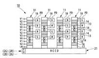
図9は、従来の固体撮像素子の構成を模式的に示した図である。図10は、図9の固体撮像素子のカラーフィルタの配列パターンを示した図である。固体撮像素子1は、格子状に複数配列された、入射光を光電変換することで信号電荷を生成するフォトダイオードPDを有している。複数のフォトダイオードPDから信号電荷を読み出しゲートで読み出して垂直方向に転送する複数の垂直電荷転送部(VCCD)を有している。複数の垂直電荷転送部によって転送された信号電荷はそれぞれ、垂直方向端部から水平電荷転送部(HCCD)に転送される。そして、水平電荷転送部で水平転送され、フローティングディフュージョンアンプFDなどの出力アンプから出力される。 FIG. 9 is a diagram schematically showing a configuration of a conventional solid-state imaging device. FIG. 10 is a diagram showing an arrangement pattern of the color filters of the solid-state imaging device of FIG. The solid-
現在、図10に示すように、赤色画素R、緑色画素G、青色画素Bに加え、輝度情報を取得するためのホワイト画素を格子状に配列させることで、色情報と輝度情報を同時に得ることができ、広いダイナミックレンジを実現できる構成が提案されている。従来、このような、カラー配列を有する撮像素子としては、例えば、下記特許文献に示すものがある。 Currently, as shown in FIG. 10, in addition to the red pixel R, the green pixel G, and the blue pixel B, the white pixels for acquiring the luminance information are arranged in a grid pattern, thereby obtaining the color information and the luminance information at the same time. A configuration that can realize a wide dynamic range has been proposed. Conventionally, as such an image sensor having a color arrangement, for example, there are those shown in the following patent documents.
上記のような撮像素子の駆動手順としては、VCCDを構成する各垂直電荷転送電極に駆動電圧供給部V1〜V4から所定の駆動パルスを印加すことで、フォトダイオードPDから読み出しだ信号電荷を順次垂直方向に転送している。例えば、図9に示す固体撮像素子1では、配列されたフォトダイオードPDのうち同じ(水平方向に並んだ)列に位置する画素の信号電荷が垂直電荷転送部VCCDに常に同時に読み出されて水平電荷転送部に転送される。 As a procedure for driving the imaging device as described above, signal charges read from the photodiode PD are sequentially applied by applying predetermined drive pulses from the drive voltage supply units V1 to V4 to the vertical charge transfer electrodes constituting the VCCD. It is transferring vertically. For example, in the solid-
ところで、上記固体撮像素子のように、同じ列のR,G,B画素とW画素との信号電荷を同時に読み出すと、静止画撮像時に高い感度で撮像を行うことができる一方で、動画撮像時のように高速出力を行うができない点で改善の余地があった。このため、RGB画素及びW画素から信号電荷を取得して撮像を行う構成の撮像素子において、高速出力と高感度とを両立させた撮像を行うことができるように駆動したいという要求があった。
また、上記構成の撮像素子では、静止画撮像時に出力信号が「G画素、W画素、R画素、W画素」や、「W画素、G画素、W画素、R画素」というように、各出力信号が隣接する出力信号と異なる色情報であり、水平電荷転送部HCCDにおいて転送不良が生じた場合に、異なる色情報の出力信号同士が混ざり合うことで画質が劣化する要因となる点で改善の余地があった。By the way, when the signal charges of the R, G, B pixels and W pixels in the same column are read simultaneously as in the above solid-state imaging device, it is possible to perform imaging with high sensitivity during still image capturing, while capturing moving images. There is room for improvement in that it cannot perform high-speed output. For this reason, there has been a demand for driving an image pickup device configured to acquire signal charges from RGB pixels and W pixels so that high-speed output and high sensitivity can be achieved.
In the imaging device having the above-described configuration, the output signal is “G pixel, W pixel, R pixel, W pixel” or “W pixel, G pixel, W pixel, R pixel” when the still image is captured. When the signal is different color information from the adjacent output signal and a transfer failure occurs in the horizontal charge transfer unit HCCD, the output signals of different color information are mixed together, which causes deterioration in image quality. There was room.
本発明は、上記事情に鑑みてなされたもので、その目的は、撮影状態に応じて、高速出力と高感度とを両立することができる固体撮像素子の駆動方法を提供することにある。 The present invention has been made in view of the above circumstances, and an object thereof is to provide a driving method of a solid-state imaging device capable of achieving both high-speed output and high sensitivity in accordance with a shooting state.
本発明の上記目的は、下記構成によって達成される。
(1)複数の色に対応するカラーフィルタが形成された撮像領域に垂直方向及び水平方向に画素ごとに設けられた光電変換部を備え、各光電変換部に入射した光に応じて信号電荷を生成し、出力することでカラー画像を得る固体撮像装置の駆動方法であって、
前記光電変換部で生成された信号電荷を読み出して、垂直電荷転送領域によって垂直方向に転送するステップと、
前記垂直電荷転送領域から転送された信号電荷を水平電荷転送領域によって水平方向に転送するステップと、
前記水平電荷転送領域において、位置が近く且つ同じ色の画素同士の信号電荷を加算して出力するステップとを有することを特徴とする固体撮像装置の駆動方法。
(2)複数の色に対応するカラーフィルタが形成された撮像領域に垂直方向及び水平方向に画素ごとに設けられた光電変換部を備え、各光電変換部に入射した光に応じて信号電荷を生成し、出力することでカラー画像を得る固体撮像装置の駆動方法であって、
前記光電変換部で生成された信号電荷を読み出して、垂直電荷転送領域によって垂直方向に転送するステップと、
前記垂直電荷転送領域から転送された信号電荷を水平電荷転送領域によって水平方向に転送するステップと、
前記水平電荷転送領域において同じ色の画素同士の信号電荷からなる出力信号群を形成し、色ごとに前記出力信号群を出力するステップとを有することを特徴とする固体撮像装置の駆動方法。
(3)前記カラーフィルタが、赤の波長の光を透過するフィルタと、緑の波長の光を透過するフィルタと、青の波長の光を透過するフィルタと、全ての波長の光を透過するフィルタとからなることを特徴とする上記(1)又は(2)に記載の固体撮像装置の駆動方法。The above object of the present invention is achieved by the following configurations.
(1) A photoelectric conversion unit provided for each pixel in a vertical direction and a horizontal direction is provided in an imaging region in which color filters corresponding to a plurality of colors are formed, and a signal charge is generated according to light incident on each photoelectric conversion unit. A method of driving a solid-state imaging device that obtains and outputs a color image by generating and outputting,
Reading out the signal charge generated by the photoelectric conversion unit and transferring it in the vertical direction by the vertical charge transfer region;
Transferring the signal charge transferred from the vertical charge transfer region in a horizontal direction by a horizontal charge transfer region;
A method of driving a solid-state imaging device, comprising: adding and outputting signal charges of pixels of the same color that are close to each other in the horizontal charge transfer region.
(2) A photoelectric conversion unit provided for each pixel in a vertical direction and a horizontal direction is provided in an imaging region in which color filters corresponding to a plurality of colors are formed, and a signal charge is generated according to light incident on each photoelectric conversion unit. A method of driving a solid-state imaging device that obtains and outputs a color image by generating and outputting,
Reading out the signal charge generated by the photoelectric conversion unit and transferring it in the vertical direction by the vertical charge transfer region;
Transferring the signal charge transferred from the vertical charge transfer region in a horizontal direction by a horizontal charge transfer region;
And a step of forming an output signal group including signal charges of pixels of the same color in the horizontal charge transfer region and outputting the output signal group for each color.
(3) The color filter is a filter that transmits light of red wavelength, a filter that transmits light of green wavelength, a filter that transmits light of blue wavelength, and a filter that transmits light of all wavelengths. The method for driving a solid-state imaging device according to (1) or (2), wherein:
本発明は、撮像時に光電変換部で生成された、色画素に対応する信号電荷を垂直電荷転送領域に読み出し、垂直電荷転送領域によって垂直転送し、その最終段から水平電荷転送領域に転送する。そして、水平電荷転送領域によって水平転送し、該水平電荷転送領域の端部から出力することでカラー画像を生成する。固体撮像装置を駆動させる際に、水平電荷転送領域によって撮像領域における配置位置が近い、同じ色の画素同士の信号電荷を加算して出力する。こうすれば、動画撮像時には、赤,緑,青の画素に対応した色信号のみを信号加算して出力することができるため、信号処理数を減らして高速出力することができる。
また、撮像駆動時に水平電荷転送領域において転送不良が生じた場合に、水平電荷転送領域において同じ色の画素同士の信号電荷からなる出力信号群を出力する手順を行うことで、画素単位で赤,緑,青及び白の画素に応じた信号電荷を転送する手順に比べて、信号電荷同士が混ざり合うことを抑制することができる。このため、転送不良に起因する画質の低下を抑えることでより高い画質の画像を得やすくなる。In the present invention, the signal charge corresponding to the color pixel generated by the photoelectric conversion unit at the time of imaging is read out to the vertical charge transfer region, vertically transferred by the vertical charge transfer region, and transferred from the final stage to the horizontal charge transfer region. Then, horizontal transfer is performed by the horizontal charge transfer region, and a color image is generated by outputting from the end of the horizontal charge transfer region. When the solid-state imaging device is driven, the signal charges of pixels of the same color whose arrangement positions in the imaging region are close by the horizontal charge transfer region are added and output. In this way, only the color signals corresponding to the red, green, and blue pixels can be added and output during moving image capturing, so that the number of signal processing can be reduced and output at high speed.
In addition, when a transfer failure occurs in the horizontal charge transfer region at the time of image pickup driving, a procedure for outputting an output signal group composed of signal charges of pixels of the same color in the horizontal charge transfer region is performed. Compared with the procedure of transferring signal charges corresponding to green, blue, and white pixels, mixing of signal charges can be suppressed. For this reason, it becomes easy to obtain a higher quality image by suppressing the deterioration of the image quality due to the transfer failure.
本発明によれば、撮影状態に応じて、高速出力と高感度とを両立することができる固体撮像素子の駆動方法を提供できる。 According to the present invention, it is possible to provide a method for driving a solid-state imaging device capable of achieving both high-speed output and high sensitivity according to a shooting state.
以下、本発明の第1実施形態を図面に基づいて詳しく説明する。
図1は、本発明にかかる固体撮像装置の概略的な構成を示す図である。
固体撮像装置10は、シリコンなどの半導体基板上に、撮像領域が区画され、該撮像領域の垂直方向(図1中の上下方向)及び水平方向(図1中の左右方向)に複数の光電変換部PDが配列されている。光電変換部PDは、被写界からの入射光を光電変換し、該入射光に応じた信号電荷を生成する構成で、例えば、フォトダイオードなどによって構成することができる。Hereinafter, a first embodiment of the present invention will be described in detail with reference to the drawings.
FIG. 1 is a diagram showing a schematic configuration of a solid-state imaging device according to the present invention.
In the solid-
撮像領域の光入射側の面には、図示しないカラーフィルタが設けられている。カラーフィルタは、図10に示すカラーフィルタと同様に、赤色,緑色,青色の波長の光を透過するフィルタと、輝度情報を所得するため、全ての波長の光を透過する輝度フィルタとを所定のパターンで配列した構成を有している。図1において、赤色のフィルタの位置に対応する光電変換部PDを「R」で示し、緑色のフィルタの位置に対応する光電変換部PDを「G」で示し、青色のフィルタの位置に対応する光電変換部PDを「B」で示し、輝度フィルタの位置に対応する光電変換部PDを「W」で示している。本実施形態では、カラーフィルタと、そのカラーフィルタに対応する光電変換部とを総称して画素とし、色ごとに赤(R)画素,緑(G)画素,青(B)画素,白(W)画素と区別する。 A color filter (not shown) is provided on the light incident side surface of the imaging region. Similar to the color filter shown in FIG. 10, the color filter includes a filter that transmits light of red, green, and blue wavelengths and a luminance filter that transmits light of all wavelengths in order to obtain luminance information. It has a configuration arranged in a pattern. In FIG. 1, the photoelectric conversion part PD corresponding to the position of the red filter is indicated by “R”, the photoelectric conversion part PD corresponding to the position of the green filter is indicated by “G”, and the position corresponds to the position of the blue filter. The photoelectric conversion unit PD is indicated by “B”, and the photoelectric conversion unit PD corresponding to the position of the luminance filter is indicated by “W”. In this embodiment, a color filter and a photoelectric conversion unit corresponding to the color filter are collectively referred to as a pixel, and a red (R) pixel, a green (G) pixel, a blue (B) pixel, and a white (W ) Differentiate from pixels.
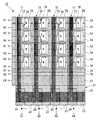
垂直方向に並んだ光電変換素子PDの列同士の間には、垂直方向に延設された垂直電荷転送部11がそれぞれ設けられている。それぞれの垂直電荷転送部11の垂直方向の転送側の端部が共通の水平電荷転送部21に接続されている。垂直電荷転送部11の半導体基板表面には垂直電荷転送チャネル12が形成され、水平電荷転送部21の半導体基板表面には水平電荷転送チャネル22が形成されている。 Between the columns of photoelectric conversion elements PD arranged in the vertical direction, vertical
垂直電荷転送部11は、光電変換素子PDから信号電荷を読み出し、垂直方向に転送する。垂直電荷転送部11は、複数段からなる垂直電荷転送電極13,14を垂直方向に対して並列し、垂直方向端部には、補助転送電極15,16が形成され、補助転送電極の転送側にはラインメモリ17が形成されている。信号電荷を転送する際には、各垂直電荷転送電極13,14及び補助転送電極15,16に所定のタイミングで垂直転送信号V1〜4を入力することで、信号電荷を垂直電荷転送部11に沿って転送し、ラインメモリ17で一旦蓄積した後で、該ラインモリ17から水平電荷転送部21へ転送する。 The vertical
垂直電荷転送電極13,14のそれぞれには、駆動時に光電変換部PDから信号電荷を読み出すための読み出し部18が形成されている。本実施形態の固体撮像装置10は、垂直電荷転送電極13の読み出し部18が、R画素、B画素、G画素に対応する光電変換部PDから信号電荷を読み出し、垂直電荷転送電極14の読み出し部18が、W画素に対応する光電変換部PDから信号電荷を読み出す構成である。読み出し部18の半導体基板表面には、図示しない読み出し領域が形成されている。 Each of the vertical
水平電荷転送部21は、ポリシリコンによって形成された第1ゲート電極23と第2ゲート電極24とからなる水平電荷転送電極を備え、第1ゲート電極23と第2ゲート電極24とを水平方向に対して交互に配置した構成である。第1ゲート電極23と第2ゲート電極24とのうち、一方がストレージ電極として機能し、他方がバリア電極として機能する。本実施形態では、第1ゲート電極23及び第2ゲート電極24には2相の水平転送信号H1,H2が入力され、信号電荷が水平電荷転送部の転送方向端部に設けられたフローティングディフュージョンアンプなどの出力アンプへ水平転送され、出力アンプで電圧変換されて出力信号として出力される。 The horizontal
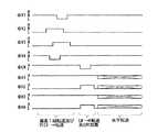
図2は、本実施形態の固体撮像装置の駆動時に、垂直電荷転送部及び水平電荷転送部に印加される転送信号のタイミングチャートである。図3は、駆動時に信号電荷が転送される状態を説明する図である。なお、図3において、R,G,B画素それぞれから読み出された信号電荷をそれぞれ丸で囲うことで示している。
固体撮像装置10の駆動時には、先ず、R,G,B画素の各光電変換部PDで生成された信号電荷を読み出し部18を介して垂直電荷転送部11に読み出す。そして、垂直電荷転送部11の垂直電荷転送電極13,14に垂直転送信号V1〜4を入力し、信号電荷を垂直電荷転送部11に沿って垂直方向に転送する。垂直電荷転送部11で転送された信号電荷は、該垂直電荷転送部11の転送方向端部の補助転送電極15,16を介してラインメモリ17に蓄積される。図2に示すように、ラインメモリ17には、所定のタイミングで読み出しパルス信号LMが入力され、ラインメモリ17にLowレベルの電圧が印加され、かつ、水平電荷転送部にHighレベルの電圧が印加ている場合に、該ラインメモリ17から水平電荷転送部21に信号電荷が転送される。FIG. 2 is a timing chart of transfer signals applied to the vertical charge transfer unit and the horizontal charge transfer unit when the solid-state imaging device of this embodiment is driven. FIG. 3 is a diagram illustrating a state where signal charges are transferred during driving. In FIG. 3, the signal charges read from the R, G, and B pixels are indicated by circles.
When the solid-
水平電荷転送部11に信号電荷が転送された後、第1ゲート電極23及び第2ゲート電極24に水平転送信号H1,H2が入力され、信号電荷が水平転送される。本実施形態では、R,G,B画素の光電変換部PDのみから信号電荷を読み出し、W画素の光電変換部PDからは信号電荷を読み出しを行わない。本実施形態の固体撮像装置10の構成では、静止画撮像時には、R,G,B画素から色情報を取得し、W画素から輝度情報を所得することで、高画質のカラー画像を生成することが可能である。一方で、動画撮像時には、上記の駆動タイミングとすることで、R,G,B画素のみを読み出し、かつ、位置の最も近い画素同士を加算して出力することができるため、出力する信号数を削減することができ、高速読み出しを実現することができる。また、信号加算することで、感度が倍となるため、W画素を用いないことでの感度低下を補うことができる。 After the signal charge is transferred to the horizontal
本実施形態では、撮像領域において互いの配置の位置が近い、同色の画素の信号電荷を水平電荷転送部21において信号加算している。具体的には、複数の垂直電荷転送部11のうち、第1垂直電荷転送列と該第1垂直電荷転送列に隣り合う第2垂直電荷転送列からB画素及びG画素の信号電荷が水平電荷転送部21に読み出され、該第2垂直電荷転送列に隣り合う第3,4垂直電荷転送列からG画素及びR画素が水平電荷転送部21に読み出される。そして、水平電荷転送部21において第1垂直電荷転送列と第2垂直電荷転送列とから読み出したG画素同士の信号電荷を信号加算し、また、B画素同士の信号電荷を信号加算する。同様に、水平電荷転送部21において第3垂直電荷転送列と第4垂直電荷転送列とから読み出したG画素同士の信号電荷を信号加算し、また、R画素同士の信号電荷を信号加算する。信号加算した後、出力アンプから信号出力する。このため、出力される信号は、同色の画素同士が加算された信号電荷からなる出力信号となる。 In the present embodiment, the horizontal
図4は、駆動時において、信号電荷が転送される別の状態を説明する図である。本実施形態の固体撮像装置10の構成では、白黒(モノクロ)画像で撮像する機能や、静止画撮像時などに焦点位置を確定するためのオートフォーカス機能(AF)を有するデジタルカメラ等の撮像装置に搭載される場合に、W画素によって輝度情報のみを取得することができる。このとき、輝度情報のみからなる画像を形成したうえで、焦点位置情報を決定し、その後で、通常の静止画撮像を開始する処理が実行可能である。なお、輝度情報のみを取得する処理は、オートフォーカス機能の処理に限定されず、他の機能においても使用することもできる。 FIG. 4 is a diagram illustrating another state in which signal charges are transferred during driving. In the configuration of the solid-
図4に示す駆動状態では、先ず、W画素の各光電変換部PDで生成された信号電荷を読み出し部18を介して垂直電荷転送部11に読み出す。そして、垂直電荷転送部11の垂直電荷転送電極13,14に垂直転送信号V1〜4を入力し、信号電荷を垂直電荷転送部11に沿って垂直方向に転送する。垂直電荷転送部11で転送された信号電荷は、該垂直電荷転送部11の転送方向端部の補助転送電極15,16を介してラインメモリ17に蓄積される。図2に示すように、ラインメモリ17には、所定のタイミングで読み出しパルス信号LMが入力され、蓄積された信号電荷が水平電荷転送部11に転送される。 In the driving state shown in FIG. 4, first, the signal charge generated by each photoelectric conversion unit PD of the W pixel is read to the vertical
水平電荷転送部11に信号電荷が転送された後、第1ゲート電極23及び第2ゲート電極24に水平転送信号H1,H2が入力され、信号電荷が水平転送される。本実施形態では、W画素の光電変換部PDのみから信号電荷を読み出す。水平電荷転送部21において第1垂直電荷転送列と第2垂直電荷転送列とから読み出したW画素同士の信号電荷を信号加算する。同様に、水平電荷転送部21において第3垂直電荷転送列と第4垂直電荷転送列とから読み出したW画素同士の信号電荷を信号加算する。信号加算した後、信号電荷を出力アンプから信号出力する。このため、出力される信号は、画素の位置が近いW画素がそれぞれ同色同士が加算された信号電荷からなる出力信号となる。 After the signal charge is transferred to the horizontal
図5は、図3の駆動状態で信号電荷を転送した場合の信号加算について模式的に示す図である。信号加算した場合に、加算されたR画素,G画素,B画素の色配列がベイヤー配列になるため、加算後においても高い解像度を得ることができる。 FIG. 5 is a diagram schematically showing signal addition when signal charges are transferred in the driving state of FIG. When signals are added, the color arrangement of the added R, G, and B pixels becomes a Bayer arrangement, so that a high resolution can be obtained even after addition.
また、本実施形態は、図3に示す読み出し手順を用いて第1フィールドの読み出しを行い、かつ、図4に示す読み出し手順を用いて第2フィールドの読み出しを行うことで画素を間引いた高速連射の静止画モードを実現することができる。図6は、信号配列を模式的に示す図である。図6に示すように、R,G,B画素がベイヤー配列となり、また、W画素はベイヤー配列された各R,G,B画素に対応して配置されるため、高解像度と高感度を両立した静止画撮像を実行することができる。 Further, in the present embodiment, high-speed continuous shooting in which pixels are thinned out by reading out the first field using the reading procedure shown in FIG. 3 and reading out the second field using the reading procedure shown in FIG. 4. The still image mode can be realized. FIG. 6 is a diagram schematically showing a signal arrangement. As shown in FIG. 6, since the R, G, and B pixels are arranged in a Bayer array and the W pixel is arranged corresponding to each of the R, G, and B pixels arranged in the Bayer array, both high resolution and high sensitivity are achieved. Still image capturing can be executed.
次に、本発明にかかる固体撮像装置の駆動方法の第2実施形態を説明する。なお、以下に説明する実施形態において、すでに説明した部材などと同等な構成・作用を有する部材等については、図中に同一符号又は相当符号を付すことにより、説明を簡略化或いは省略する。なお、本実施形態の固体撮像装置の構成は、上記第1実施形態の構成と同じである。 Next, a second embodiment of the driving method of the solid-state imaging device according to the present invention will be described. In the embodiments described below, members having the same configuration / action as those already described are denoted by the same or corresponding reference numerals in the drawings, and description thereof is simplified or omitted. Note that the configuration of the solid-state imaging device of the present embodiment is the same as that of the first embodiment.
図7は、本実施形態の固体撮像装置の駆動時に、垂直電荷転送部及び水平電荷転送部に印加される転送信号のタイミングチャートである。図8は、駆動時に信号電荷が転送される状態を説明する図である。
固体撮像装置10の駆動時には、先ず、R,G,B画素の各光電変換部PDで生成された信号電荷を読み出し部18を介して垂直電荷転送部11に読み出す。そして、垂直電荷転送部11の垂直電荷転送電極13,14に垂直転送信号V1〜4を入力し、信号電荷を垂直電荷転送部11に沿って垂直方向に転送する。垂直電荷転送部11で転送された信号電荷は、該垂直電荷転送部11の転送方向端部の補助転送電極15,16を介してラインメモリ17に蓄積される。ラインメモリ17には、所定のタイミングで読み出しパルス信号LMが入力されることで、該ラインメモリ17から水平電荷転送部21に信号電荷が転送される。FIG. 7 is a timing chart of transfer signals applied to the vertical charge transfer unit and the horizontal charge transfer unit when the solid-state imaging device of the present embodiment is driven. FIG. 8 is a diagram for explaining a state where signal charges are transferred during driving.
When the solid-
水平電荷転送部11に信号電荷が転送された後、第1ゲート電極23及び第2ゲート電極24に水平転送信号H1,H2が入力され、信号電荷が水平転送される。本実施形態では、R,G,B画素の光電変換部PDのみから信号電荷を読み出し、W画素の光電変換部PDからは信号電荷を読み出しを行わない。 After the signal charge is transferred to the horizontal
本実施形態では、上記の駆動タイミングで信号電荷の読み出した場合に、フィールドの1ラインにおいて出力される信号電荷が同色の画素の信号電荷のみからなる出力信号群を形成する。そして、色ごとに出力信号群を出力する。従来では、転送不良に起因して水平電荷転送部の転送効率が悪い場合には、異なる画素同士の信号電荷が水平電荷転送部において混ざり合うことで混色が発生していた。そこで、本実施形態の駆動方法によれば、転送不良が発生しても、水平電荷転送部において混ざり合うことを抑制することができ、画質の劣化を抑えた、高画質の画像を得ることが可能となる。なお、図4に示す駆動方法を用いたフィールドにおいては、全ての出力信号がホワイトとなるため、駆動タイミングは本実施形態のものに限定されない。 In the present embodiment, when the signal charge is read out at the above driving timing, an output signal group is formed in which the signal charge output in one line of the field is composed only of the signal charges of pixels of the same color. Then, an output signal group is output for each color. Conventionally, when the transfer efficiency of the horizontal charge transfer unit is poor due to a transfer failure, color mixture occurs because signal charges of different pixels are mixed in the horizontal charge transfer unit. Therefore, according to the driving method of the present embodiment, even if a transfer failure occurs, mixing in the horizontal charge transfer unit can be suppressed, and a high-quality image with reduced image quality can be obtained. It becomes possible. In the field using the driving method shown in FIG. 4, since all output signals are white, the driving timing is not limited to that of this embodiment.
10 固体撮像装置
11 垂直電荷転送部
13,14 垂直電荷転送電極
21 水平電荷転送部
23,24 水平電荷転送電極
PD 光電変換部DESCRIPTION OF
Claims (3)
Translated fromJapanese前記光電変換部で生成された信号電荷を読み出して、垂直電荷転送領域によって垂直方向に転送するステップと、
前記垂直電荷転送領域から転送された信号電荷を水平電荷転送領域によって水平方向に転送するステップと、
前記水平電荷転送領域において、位置が近く且つ同じ色の画素同士の信号電荷を加算して出力するステップとを有することを特徴とする固体撮像装置の駆動方法。A photoelectric conversion unit provided for each pixel in a vertical direction and a horizontal direction in an imaging region in which color filters corresponding to a plurality of colors are formed, generates a signal charge according to light incident on each photoelectric conversion unit, A solid-state imaging device driving method for obtaining a color image by outputting,
Reading out the signal charge generated by the photoelectric conversion unit and transferring it in the vertical direction by the vertical charge transfer region;
Transferring the signal charge transferred from the vertical charge transfer region in a horizontal direction by a horizontal charge transfer region;
A method of driving a solid-state imaging device, comprising: adding and outputting signal charges of pixels of the same color that are close to each other in the horizontal charge transfer region.
前記光電変換部で生成された信号電荷を読み出して、垂直電荷転送領域によって垂直方向に転送するステップと、
前記垂直電荷転送領域から転送された信号電荷を水平電荷転送領域によって水平方向に転送するステップと、
前記水平電荷転送領域において同じ色の画素同士の信号電荷からなる出力信号群を形成し、色ごとに前記出力信号群を出力するステップとを有することを特徴とする固体撮像装置の駆動方法。A photoelectric conversion unit provided for each pixel in a vertical direction and a horizontal direction in an imaging region in which color filters corresponding to a plurality of colors are formed, generates a signal charge according to light incident on each photoelectric conversion unit, A solid-state imaging device driving method for obtaining a color image by outputting,
Reading out the signal charge generated by the photoelectric conversion unit and transferring it in the vertical direction by the vertical charge transfer region;
Transferring the signal charge transferred from the vertical charge transfer region in a horizontal direction by a horizontal charge transfer region;
And a step of forming an output signal group including signal charges of pixels of the same color in the horizontal charge transfer region and outputting the output signal group for each color.
Priority Applications (1)
| Application Number | Priority Date | Filing Date | Title |
|---|---|---|---|
| JP2007286373AJP2009117979A (en) | 2007-11-02 | 2007-11-02 | Driving method of solid-state imaging device |
Applications Claiming Priority (1)
| Application Number | Priority Date | Filing Date | Title |
|---|---|---|---|
| JP2007286373AJP2009117979A (en) | 2007-11-02 | 2007-11-02 | Driving method of solid-state imaging device |
Publications (1)
| Publication Number | Publication Date |
|---|---|
| JP2009117979Atrue JP2009117979A (en) | 2009-05-28 |
Family
ID=40784648
Family Applications (1)
| Application Number | Title | Priority Date | Filing Date |
|---|---|---|---|
| JP2007286373AAbandonedJP2009117979A (en) | 2007-11-02 | 2007-11-02 | Driving method of solid-state imaging device |
Country Status (1)
| Country | Link |
|---|---|
| JP (1) | JP2009117979A (en) |
Cited By (8)
| Publication number | Priority date | Publication date | Assignee | Title |
|---|---|---|---|---|
| JP2010136225A (en)* | 2008-12-08 | 2010-06-17 | Sony Corp | Solid-state imaging device, method of processing signal of the same, and image capturing apparatus |
| JP2010136226A (en)* | 2008-12-08 | 2010-06-17 | Sony Corp | Solid-state imaging device, method of processing signal of the same, and image capturing apparatus |
| JP2013192214A (en)* | 2012-02-16 | 2013-09-26 | Panasonic Corp | Imaging element and imaging device |
| JP2014161022A (en)* | 2014-03-12 | 2014-09-04 | Sony Corp | Solid-state imaging apparatus, signal processing method of the same and imaging apparatus |
| WO2015008635A1 (en)* | 2013-07-17 | 2015-01-22 | ソニー株式会社 | Solid-state imaging element, method for driving same, and electronic apparatus |
| US20150029377A1 (en)* | 2013-07-29 | 2015-01-29 | Sony Corporation | Solid-state imaging device, driving method for the same, and electronic apparatus |
| US9083842B2 (en) | 2008-12-08 | 2015-07-14 | Sony Corporation | Solid-state imaging device, method for processing signal of solid-state imaging device, and imaging apparatus |
| CN116055896A (en)* | 2022-12-29 | 2023-05-02 | 维沃移动通信有限公司 | Image generation method and device and electronic device |
Citations (5)
| Publication number | Priority date | Publication date | Assignee | Title |
|---|---|---|---|---|
| JP2000350099A (en)* | 1999-06-08 | 2000-12-15 | Fuji Film Microdevices Co Ltd | Solid-state image pickup unit and control method therefor |
| JP2004080690A (en)* | 2002-08-22 | 2004-03-11 | Matsushita Electric Ind Co Ltd | CCD solid-state imaging device and camera system using the same |
| JP2004228157A (en)* | 2003-01-20 | 2004-08-12 | Sony Corp | Solid-state imaging device |
| JP2007201712A (en)* | 2006-01-25 | 2007-08-09 | Fujifilm Corp | IMAGING DEVICE, CCD TYPE SOLID-STATE IMAGING ELEMENT MOUNTED ON THE IMAGING DEVICE, AND ITS DRIVING METHOD |
| JP2007258686A (en)* | 2006-02-23 | 2007-10-04 | Fujifilm Corp | Solid-state imaging device and imaging apparatus |
- 2007
- 2007-11-02JPJP2007286373Apatent/JP2009117979A/ennot_activeAbandoned
Patent Citations (5)
| Publication number | Priority date | Publication date | Assignee | Title |
|---|---|---|---|---|
| JP2000350099A (en)* | 1999-06-08 | 2000-12-15 | Fuji Film Microdevices Co Ltd | Solid-state image pickup unit and control method therefor |
| JP2004080690A (en)* | 2002-08-22 | 2004-03-11 | Matsushita Electric Ind Co Ltd | CCD solid-state imaging device and camera system using the same |
| JP2004228157A (en)* | 2003-01-20 | 2004-08-12 | Sony Corp | Solid-state imaging device |
| JP2007201712A (en)* | 2006-01-25 | 2007-08-09 | Fujifilm Corp | IMAGING DEVICE, CCD TYPE SOLID-STATE IMAGING ELEMENT MOUNTED ON THE IMAGING DEVICE, AND ITS DRIVING METHOD |
| JP2007258686A (en)* | 2006-02-23 | 2007-10-04 | Fujifilm Corp | Solid-state imaging device and imaging apparatus |
Cited By (12)
| Publication number | Priority date | Publication date | Assignee | Title |
|---|---|---|---|---|
| JP2010136225A (en)* | 2008-12-08 | 2010-06-17 | Sony Corp | Solid-state imaging device, method of processing signal of the same, and image capturing apparatus |
| JP2010136226A (en)* | 2008-12-08 | 2010-06-17 | Sony Corp | Solid-state imaging device, method of processing signal of the same, and image capturing apparatus |
| US9083842B2 (en) | 2008-12-08 | 2015-07-14 | Sony Corporation | Solid-state imaging device, method for processing signal of solid-state imaging device, and imaging apparatus |
| JP2013192214A (en)* | 2012-02-16 | 2013-09-26 | Panasonic Corp | Imaging element and imaging device |
| WO2015008635A1 (en)* | 2013-07-17 | 2015-01-22 | ソニー株式会社 | Solid-state imaging element, method for driving same, and electronic apparatus |
| US20150029377A1 (en)* | 2013-07-29 | 2015-01-29 | Sony Corporation | Solid-state imaging device, driving method for the same, and electronic apparatus |
| JP2015027045A (en)* | 2013-07-29 | 2015-02-05 | ソニー株式会社 | Solid-state imaging device, driving method thereof and electronic apparatus |
| CN104349146A (en)* | 2013-07-29 | 2015-02-11 | 索尼公司 | Solid-state imaging device, driving method for the same, and electronic apparatus |
| US9317897B2 (en) | 2013-07-29 | 2016-04-19 | Sony Corporation | Solid-state imaging device, driving method for the same, and electronic apparatus |
| JP2014161022A (en)* | 2014-03-12 | 2014-09-04 | Sony Corp | Solid-state imaging apparatus, signal processing method of the same and imaging apparatus |
| CN116055896A (en)* | 2022-12-29 | 2023-05-02 | 维沃移动通信有限公司 | Image generation method and device and electronic device |
| CN116055896B (en)* | 2022-12-29 | 2025-09-09 | 维沃移动通信有限公司 | Image generation method and device and electronic device |
Similar Documents
| Publication | Publication Date | Title |
|---|---|---|
| US8054342B2 (en) | Imaging apparatus and method for driving the imaging apparatus | |
| US7944496B2 (en) | Imaging apparatus and driving method for CCD type solid-state imaging device | |
| US8300131B2 (en) | Image pickup device for wide dynamic range at a high frame rate | |
| US7440019B2 (en) | Solid-state image pick-up device | |
| JP4984981B2 (en) | Imaging method, imaging apparatus, and driving apparatus | |
| JP4887314B2 (en) | Imaging apparatus and image signal processing method | |
| JP4951440B2 (en) | Imaging apparatus and solid-state imaging device driving method | |
| JP4448889B2 (en) | Imaging device and imaging apparatus | |
| JP2009117979A (en) | Driving method of solid-state imaging device | |
| KR20090023186A (en) | Driving Method of Imaging Device and Solid State Imaging Device | |
| US20110216228A1 (en) | Solid-state image sensing element, method for driving solid-state image sensing element and image pickup device | |
| US7683956B2 (en) | Solid-state imaging device, driving method thereof, and camera that separate image component signal and non-image component signal | |
| JP2007135200A (en) | Imaging method, imaging device, and driver | |
| JP4393242B2 (en) | Solid-state imaging device and driving method of solid-state imaging device | |
| US20090059050A1 (en) | Imaging apparatus and driving method of ccd type solid-state imaging device | |
| JP2010081286A (en) | Image pickup device | |
| JP2007235888A (en) | Single-plate color solid-state imaging device and imaging apparatus | |
| JP2007325181A (en) | Method for driving CCD type solid-state imaging device, solid-state imaging device | |
| JP4848349B2 (en) | Imaging apparatus and solid-state imaging device driving method | |
| JP2009141578A (en) | Solid-state imaging device driving method, signal processing method, and imaging apparatus | |
| JP2008244886A (en) | Solid-state image sensor, method of driving solid-state image sensor, and camera system | |
| JP5256084B2 (en) | Imaging device and driving method of imaging device | |
| JP2007201711A (en) | Imaging device and charge transfer method for CCD solid-state imaging device | |
| JP2009141404A (en) | Drive control method and image pickup apparatus for CCD solid-state image pickup device | |
| JP2009141579A (en) | Solid-state imaging device driving method, signal processing method, and imaging apparatus |
Legal Events
| Date | Code | Title | Description |
|---|---|---|---|
| A621 | Written request for application examination | Free format text:JAPANESE INTERMEDIATE CODE: A621 Effective date:20100707 | |
| A977 | Report on retrieval | Free format text:JAPANESE INTERMEDIATE CODE: A971007 Effective date:20110413 | |
| A131 | Notification of reasons for refusal | Free format text:JAPANESE INTERMEDIATE CODE: A131 Effective date:20110419 | |
| A762 | Written abandonment of application | Free format text:JAPANESE INTERMEDIATE CODE: A762 Effective date:20110510 |