JP2009115584A - Navigation device - Google Patents
Navigation deviceDownload PDFInfo
- Publication number
- JP2009115584A JP2009115584AJP2007288313AJP2007288313AJP2009115584AJP 2009115584 AJP2009115584 AJP 2009115584AJP 2007288313 AJP2007288313 AJP 2007288313AJP 2007288313 AJP2007288313 AJP 2007288313AJP 2009115584 AJP2009115584 AJP 2009115584A
- Authority
- JP
- Japan
- Prior art keywords
- facility
- destination
- map image
- polygon
- storage unit
- Prior art date
- Legal status (The legal status is an assumption and is not a legal conclusion. Google has not performed a legal analysis and makes no representation as to the accuracy of the status listed.)
- Granted
Links
Images


Classifications
- G—PHYSICS
- G01—MEASURING; TESTING
- G01C—MEASURING DISTANCES, LEVELS OR BEARINGS; SURVEYING; NAVIGATION; GYROSCOPIC INSTRUMENTS; PHOTOGRAMMETRY OR VIDEOGRAMMETRY
- G01C21/00—Navigation; Navigational instruments not provided for in groups G01C1/00 - G01C19/00
- G01C21/26—Navigation; Navigational instruments not provided for in groups G01C1/00 - G01C19/00 specially adapted for navigation in a road network
Landscapes
- Engineering & Computer Science (AREA)
- Radar, Positioning & Navigation (AREA)
- Remote Sensing (AREA)
- Automation & Control Theory (AREA)
- Physics & Mathematics (AREA)
- General Physics & Mathematics (AREA)
- Navigation (AREA)
- Instructional Devices (AREA)
- Traffic Control Systems (AREA)
Abstract
Translated fromJapaneseDescription
Translated fromJapanese本発明は、ナビゲーション装置に関する。 The present invention relates to a navigation device.
従来、例えば表示画面に表示された地図画像上を移動可能なカーソルにより目的地を設定するナビゲーション装置が知られている(例えば、特許文献1、特許文献2参照)。
ところで、上記従来技術に係るナビゲーション装置において、地図画像上のカーソルの位置に応じて目的地を設定する際に、予め住所等の位置情報を有する地図画像上の複数の位置(つまり、カーソルにより選択可能な選択可能位置)のうちカーソルの位置に最も近い位置を選択して、この位置の住所等の位置情報を目的地として設定する場合には、目的地が適切に設定されない虞がある。
例えば操作者が適宜の施設を目的地として設定する際に、この施設に対応する地図画像上のポリゴンにカーソルの位置を設定すると、このカーソルの位置に最も近い選択可能位置が選択されることになり、この選択可能位置が、例えば施設の入り口等の相対的に重要度が高い所定位置から離間している場合には、目的地に対する経路誘導が不適切となってしまうという問題が生じる。By the way, in the navigation device according to the above prior art, when setting the destination according to the position of the cursor on the map image, a plurality of positions on the map image having position information such as addresses in advance (that is, selected by the cursor) When the position closest to the cursor position is selected from the possible selectable positions) and the position information such as the address of this position is set as the destination, the destination may not be set appropriately.
For example, when an operator sets an appropriate facility as a destination, if the cursor position is set to a polygon on a map image corresponding to the facility, a selectable position closest to the cursor position is selected. Thus, when the selectable position is separated from a predetermined position having a relatively high importance such as an entrance of a facility, there arises a problem that route guidance to the destination becomes inappropriate.
本発明は上記事情に鑑みてなされたもので、目的地を適切に設定することが可能なナビゲーション装置を提供することを目的とする。 The present invention has been made in view of the above circumstances, and an object thereof is to provide a navigation apparatus capable of appropriately setting a destination.
上記課題を解決して係る目的を達成するために、本発明の第1態様に係るナビゲーション装置は、施設名が対応付けられたポリゴンを具備する地図画像を記憶する地図画像記憶手段(例えば、実施の形態での地図データ記憶部12)と、前記施設名と施設位置とを対応付けて記憶する施設情報記憶手段(例えば、実施の形態での施設データ記憶部13)と、前記地図画像および前記地図画像上を移動可能な指示画像を表示する表示手段(例えば、実施の形態での表示装置51)と、前記地図画像上の位置を前記指示画像により指定する位置指定手段(例えば、実施の形態での入力操作部14およびECU15)と、前記位置指定手段により指定された前記地図画像上の位置に基づき、目的地を設定する目的地設定手段(例えば、実施の形態での入力操作部14およびECU15、ステップS01〜ステップS04)とを備え、前記目的地設定手段は、前記位置指定手段により前記地図画像における前記ポリゴン上の任意の位置が指定された場合、前記地図画像記憶手段に記憶された前記ポリゴンに対応する前記施設名を用いて、前記施設情報記憶手段に記憶された前記施設名および前記施設位置を検索することで、前記ポリゴンに対応する前記施設名に対応付けられた前記施設位置を抽出し、抽出された前記施設位置を前記目的地として設定する。 In order to solve the above-described problems and achieve the object, the navigation apparatus according to the first aspect of the present invention is a map image storage means (for example, implementation) that stores a map image having polygons associated with facility names. Map data storage unit 12) in the form of, a facility information storage means for storing the facility name and the facility position in association with each other (for example, the facility
さらに、本発明の第2態様に係るナビゲーション装置では、前記施設情報記憶手段は、前記施設位置を駐車場の位置とし、前記施設名と前記駐車場の位置とを対応付けて記憶する。 Further, in the navigation device according to the second aspect of the present invention, the facility information storage means stores the facility name in association with the parking lot location, with the facility location as a parking lot location.
本発明の第1態様に係るナビゲーション装置によれば、地図画像におけるポリゴン上の任意の位置が指定された場合に、このポリゴンに対応する施設名を用いて、施設情報記憶手段に記憶された施設位置を抽出し、この施設位置を目的地として設定することから、予め施設位置として、例えば施設の入り口の位置等を設定しておくことにより、操作者の入力操作に応じて適切な目的地を設定することができる。 According to the navigation device of the first aspect of the present invention, when an arbitrary position on the polygon in the map image is designated, the facility stored in the facility information storage means using the facility name corresponding to this polygon Since the location is extracted and this facility location is set as the destination, by setting the location of the entrance of the facility in advance as the facility location, an appropriate destination can be selected according to the input operation of the operator. Can be set.
さらに、本発明の第2態様に係るナビゲーション装置によれば、施設位置を駐車場の位置とすることにより、車両に対して適切な目的地を設定することができる。 Furthermore, according to the navigation apparatus which concerns on the 2nd aspect of this invention, a suitable destination can be set with respect to a vehicle by making a facility position into the position of a parking lot.
以下、本発明のナビゲーション装置の一実施形態について添付図面を参照しながら説明する。
本実施の形態によるナビゲーション装置10は、例えば図1に示すように、例えば現在位置検出部11と、地図データ記憶部12と、施設データ記憶部13と、入力操作部14と、ECU15と、出力部16とを備えて構成されている。Hereinafter, an embodiment of a navigation device of the present invention will be described with reference to the accompanying drawings.
As shown in FIG. 1, for example, the
現在位置検出部11は、例えば人工衛星を利用して車両の位置を測定するためのGPS(Global Positioning System)信号や、例えば適宜の基地局を利用してGPS信号の誤差を補正して測位精度を向上させるためのD(Differential)GPS信号等の測位信号を受信する測位信号受信部21と、水平面内での自車両の向きや鉛直方向に対する傾斜角度(例えば、車両の前後方向軸の鉛直方向に対する傾斜角度や車両重心の上下方向軸回りの回転角であるヨー角等)および傾斜角度の変化量(例えば、ヨーレート等)を検出するジャイロセンサ22と、車両の速度(車速)を検出する車速センサ23とを備えて構成され、受信した測位信号によって、あるいは、車速やヨーレート等の検出信号に基づく自律航法の算出処理によって、車両の現在位置を算出する。 The current
地図データ記憶部12は、例えば出力部16の表示装置51の表示画面51a上において地図を表示するための地図データと、道路の接続状態および形状等の情報からなる道路データとを格納している。
地図データは、例えば地形図のデータと、例えば各種の施設および街区および湖沼等に対応したポリゴンのデータと、例えば各ポリゴンに対応付けられた施設名および地名等の文字のデータと、各種の記号のデータとを備えて構成されている。
道路データは、例えばノード(つまり、道路形状を把握するための座標点)および各ノード間を結ぶ線であるリンクと、各リンクの距離と、道路の種別および幅員および交差角度および形状等のデータを備えて構成されている。The map
The map data includes, for example, topographic map data, polygon data corresponding to various facilities and blocks, lakes, and the like, character data such as facility names and place names associated with the polygons, and various symbols, for example. Data.
The road data includes, for example, nodes (that is, coordinate points for grasping the road shape), links that are lines connecting the nodes, distances of the links, road types, widths, intersection angles, shapes, and the like. It is configured with.
施設データ記憶部13は、例えばPOI(Point Of Interest)データとして、例えば各種の施設の施設名および各施設名に対応付けられた施設位置(例えば、施設に具備される駐車場の座標、または、施設の入り口の座標等)および各施設名に対応付けられた電話番号等のデータを格納している。 The facility
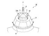
入力操作部14は、例えば図2〜図4に示すように、出力部16の表示装置51から下方側にずれた位置でインスツルメントパネルから突出する回転操作部材31およびスライド操作部材32を備えて構成されている。
略円筒状の回転操作部材31は、軸線P周り(例えば、図3に示す矢印R方向)に回転可能とされている。
回転操作部材31の内径よりも小さな外径を有する略円柱状のスライド操作部材32は、回転操作部材31と同軸に回転操作部材31の内部に配置され、スライド操作部材32の先端部32aは、回転操作部材31の開口端31aから突出するように配置され、スライド操作部材32は、軸線P方向および軸線Pに直交する任意の方向(例えば、図3に示す矢印X,Y方向)に変位可能とされている。As shown in FIGS. 2 to 4, for example, the
The substantially cylindrical
The substantially cylindrical
スライド操作部材32には、軸線P方向および軸線Pに直交する方向に対して所定の基準位置が設定され、操作者からの入力操作(例えば、軸線P方向の押下操作、または、軸線Pに直交する方向のスライド操作等)が無い場合には、適宜の復帰機構(図示略)により基準位置に自動的に復帰するように設定されている。
また、入力操作部14は、回転操作部材31の回転角度および回転速度を検出するエンコーダ等のセンサ(図示略)と、スライド操作部材32の軸線P方向および軸線Pに直交する方向での各所定変位を検出するセンサ(図示略)とを備え、各センサから出力される検出値の信号はECU15に入力されている。A predetermined reference position is set in the
Further, the
ECU15は、例えば記憶部41と、ナビゲーション処理部42と、出力制御部43とを備えて構成されている。 The
記憶部41は、例えば現在位置検出部11から出力される現在位置を記憶すると共に、例えば入力操作部14に対する操作者の入力操作等によって設定される目的地を記憶する。
また、記憶部41は、例えば入力操作部14に対する操作者の入力操作に応じて、複数の目的地のうち、何れか1つの目的地を最終目的地とし、この最終目的地以外の他の目的地を現在位置と最終目的地との間での経由地として記憶すると共に、全ての目的地に対して設定される経由順序を記憶する。The
Further, the
ナビゲーション処理部42は、例えば、地図データ記憶部12から取得する道路データに対して、現在位置検出部11から出力される現在位置に基づいてマップマッチングを行うと共に、入力操作部14に対する操作者の入力操作に応じて設定された目的地に対して経路探索や経路誘導等の処理を実行し、出力部16の表示装置51およびスピーカ52の動作を指示する制御指令を出力する。
出力制御部43は、例えば、ナビゲーション処理部42から出力される制御指令あるいは入力操作部14に対する操作者の入力操作に応じて、出力部16の表示装置51およびスピーカ52を制御する。For example, the
The
この実施の形態によるナビゲーション装置10は上記構成を備えており、次に、このナビゲーション装置10の動作、特に、目的地を設定する処理について説明する。 The
ナビゲーション処理部42は、例えば入力操作部14に対する操作者の入力操作等に応じて、表示画面51aに表示されている地図におけるポリゴン上の任意の位置が目的地として指定された場合、予め地図データ記憶部12に記憶されたポリゴンに対応する施設名を用いて、予め施設データ記憶部13に記憶された施設名および施設名に対応付けられた施設位置を検索することで、操作者により指定されたポリゴンに対応する施設名に対応付けられた施設位置を抽出し、抽出した施設位置を目的地として設定する。 For example, when an arbitrary position on the polygon in the map displayed on the
例えば図5(a)に示すように、地図データ記憶部12から取得された地図の画像(地図画像)61および地図画像61上を移動可能な指示画像62が表示装置51の表示画面51aに表示され、指示画像62が地図画像61におけるポリゴン63上の任意の位置を指示する状態で、操作者により目的地を設定する所定の確定操作(例えば、入力操作部14のスライド操作部材32に対する軸線P方向の押下操作等)が実行されると、ナビゲーション処理部42は、予め地図データ記憶部12に記憶されたポリゴン63に対応する施設名を用いて、予め施設データ記憶部13に記憶された施設名および施設名に対応付けられた施設位置(例えば、施設に具備される駐車場の座標、または、施設の入り口の座標等)を検索する。そして、検索して得た施設位置を目的地として設定し、例えば図5(b)に示すように、この目的地の位置を示す画像64を表示画面51aの地図画像61上に表示する。 For example, as shown in FIG. 5A, a map image (map image) 61 acquired from the map
以下に、目的地を設定する一連の処理について説明する。
先ず、例えば図6に示すステップS01においては、表示装置51の表示画面51aにおいて地図画像61上を移動可能な指示画像62により指示されると共に、目的地を設定する所定の確定操作(例えば、入力操作部14のスライド操作部材32に対する軸線P方向の押下操作等)によって操作者により選択されるポリゴン63を取得する。
そして、ステップS02においては、操作者により選択されたポリゴン63に対応する施設名を地図データ記憶部12から取得し、この施設名と同じ施設名を具備するPOIデータを検索する。A series of processes for setting the destination will be described below.
First, for example, in step S01 shown in FIG. 6, a predetermined confirmation operation (for example, input) is performed by an
In step S02, the facility name corresponding to the
そして、ステップS03においては、施設データ記憶部13から検索して得たPOIデータから、施設名に対応付けられた施設位置(例えば、施設に具備される駐車場の座標、または、施設の入り口の座標等)を取得する。
そして、ステップS04においては、取得した施設位置を目的地として設定する。
そして、ステップS05においては、目的地の位置を表示画面51aの地図画像61上に表示し、一連の処理を終了する。In step S03, from the POI data obtained by searching from the facility
In step S04, the acquired facility position is set as the destination.
In step S05, the position of the destination is displayed on the
上述したように、本実施の形態によるナビゲーション装置10によれば、表示装置51の表示画面51aの地図画像61におけるポリゴン63上の任意の位置が目的地として操作者により指定された場合に、このポリゴン63に対応する施設名を用いて、施設データ記憶部13に記憶された施設位置を抽出し、この施設位置を目的地として設定することから、予め施設位置として、例えば施設に具備される駐車場の座標、または、施設の入り口の座標等を設定しておくことにより、操作者の入力操作に応じて適切な目的地を設定することができる。
しかも、施設データ記憶部13に記憶される施設名に対応付けられた施設位置を駐車場の位置とした場合には、車両に対して適切な目的地を設定することができる。As described above, according to the
In addition, when the facility position associated with the facility name stored in the facility
10 ナビゲーション装置
12 地図データ記憶部(地図画像記憶手段)
13 施設データ記憶部(施設情報記憶手段)
14 入力操作部(位置指定手段、目的地設定手段)
15 ECU(位置指定手段、目的地設定手段)
51 表示装置(表示手段)
ステップS01〜ステップS04 目的地設定手段10
13 Facility data storage (facility information storage means)
14 Input operation section (position specifying means, destination setting means)
15 ECU (position specifying means, destination setting means)
51 Display device (display means)
Step S01 to Step S04 Destination setting means
Claims (2)
Translated fromJapanese前記施設名と施設位置とを対応付けて記憶する施設情報記憶手段と、
前記地図画像および前記地図画像上を移動可能な指示画像を表示する表示手段と、
前記地図画像上の位置を前記指示画像により指定する位置指定手段と、
前記位置指定手段により指定された前記地図画像上の位置に基づき、目的地を設定する目的地設定手段とを備え、
前記目的地設定手段は、
前記位置指定手段により前記地図画像における前記ポリゴン上の任意の位置が指定された場合、前記地図画像記憶手段に記憶された前記ポリゴンに対応する前記施設名を用いて、前記施設情報記憶手段に記憶された前記施設名および前記施設位置を検索することで、前記ポリゴンに対応する前記施設名に対応付けられた前記施設位置を抽出し、抽出された前記施設位置を前記目的地として設定することを特徴とするナビゲーション装置。Map image storage means for storing a map image having a polygon associated with a facility name;
Facility information storage means for storing the facility name and the facility position in association with each other;
Display means for displaying the map image and an instruction image movable on the map image;
Position specifying means for specifying a position on the map image by the instruction image;
A destination setting means for setting a destination based on the position on the map image designated by the position designation means;
The destination setting means includes
When an arbitrary position on the polygon in the map image is designated by the position designation unit, the facility information storage unit stores the facility name corresponding to the polygon stored in the map image storage unit. The facility name associated with the facility name corresponding to the polygon is extracted by searching for the facility name and the facility position, and the extracted facility position is set as the destination. A featured navigation device.
Priority Applications (2)
| Application Number | Priority Date | Filing Date | Title |
|---|---|---|---|
| JP2007288313AJP4732421B2 (en) | 2007-11-06 | 2007-11-06 | Navigation device |
| US12/265,374US20090119007A1 (en) | 2007-11-06 | 2008-11-05 | Navigation System |
Applications Claiming Priority (1)
| Application Number | Priority Date | Filing Date | Title |
|---|---|---|---|
| JP2007288313AJP4732421B2 (en) | 2007-11-06 | 2007-11-06 | Navigation device |
Publications (2)
| Publication Number | Publication Date |
|---|---|
| JP2009115584Atrue JP2009115584A (en) | 2009-05-28 |
| JP4732421B2 JP4732421B2 (en) | 2011-07-27 |
Family
ID=40589038
Family Applications (1)
| Application Number | Title | Priority Date | Filing Date |
|---|---|---|---|
| JP2007288313AExpired - Fee RelatedJP4732421B2 (en) | 2007-11-06 | 2007-11-06 | Navigation device |
Country Status (2)
| Country | Link |
|---|---|
| US (1) | US20090119007A1 (en) |
| JP (1) | JP4732421B2 (en) |
Cited By (1)
| Publication number | Priority date | Publication date | Assignee | Title |
|---|---|---|---|---|
| JP2011203244A (en)* | 2010-03-03 | 2011-10-13 | Denso Corp | Navigation system and program for the same |
Families Citing this family (4)
| Publication number | Priority date | Publication date | Assignee | Title |
|---|---|---|---|---|
| JP2011095238A (en)* | 2009-09-30 | 2011-05-12 | Aisin Aw Co Ltd | Navigation device and program |
| WO2011158336A1 (en)* | 2010-06-15 | 2011-12-22 | 株式会社ナビタイムジャパン | Navigation system, terminal apparatus, navigation server, navigation apparatus, navigation method, and program |
| JP5775076B2 (en)* | 2010-06-16 | 2015-09-09 | 株式会社ナビタイムジャパン | Navigation system, terminal device, navigation server, navigation method, and program |
| WO2012000530A1 (en)* | 2010-07-02 | 2012-01-05 | Elektrobit Automotive Gmbh | Provision of database objects for destination search by a navigation device |
Citations (9)
| Publication number | Priority date | Publication date | Assignee | Title |
|---|---|---|---|---|
| JPH08110755A (en)* | 1994-10-07 | 1996-04-30 | Aisin Aw Co Ltd | Map calling device for navigation system |
| JPH1089976A (en)* | 1996-09-13 | 1998-04-10 | Hitachi Ltd | Information display device and navigation system |
| JP2000292179A (en)* | 1999-04-02 | 2000-10-20 | Sumitomo Electric Ind Ltd | Mobile data communication system |
| JP2000337913A (en)* | 1999-05-24 | 2000-12-08 | Fujitsu Ten Ltd | Method and apparatus for acquiring point name in navigation device |
| JP2003157135A (en)* | 1996-07-31 | 2003-05-30 | Aisin Aw Co Ltd | Information display unit with touch panel, navigation device, and recording medium |
| JP2003212000A (en)* | 2002-01-25 | 2003-07-30 | Nippon Seiki Co Ltd | Display device and display method |
| JP2004053304A (en)* | 2002-07-17 | 2004-02-19 | Alpine Electronics Inc | Navigation device |
| JP2004126116A (en)* | 2002-10-01 | 2004-04-22 | Zenrin Co Ltd | Designation of location in three-dimensionally displayed electronic map |
| JP2004138581A (en)* | 2002-10-21 | 2004-05-13 | Matsushita Electric Ind Co Ltd | Map display device and map display method |
Family Cites Families (4)
| Publication number | Priority date | Publication date | Assignee | Title |
|---|---|---|---|---|
| JP2916842B2 (en)* | 1992-11-11 | 1999-07-05 | アルプス電気株式会社 | Screen display control device |
| DE69524340T2 (en)* | 1994-09-22 | 2002-08-14 | Aisin Aw Co | Touch display for an information entry system |
| KR100235239B1 (en)* | 1995-09-29 | 1999-12-15 | 모리 하루오 | Apparatus for outputting mold information, method for outputting mold information, map display apparatus, map display method, navigation apparatus and navigation method |
| KR100260760B1 (en)* | 1996-07-31 | 2000-07-01 | 모리 하루오 | Information display device with a touch panel |
- 2007
- 2007-11-06JPJP2007288313Apatent/JP4732421B2/ennot_activeExpired - Fee Related
- 2008
- 2008-11-05USUS12/265,374patent/US20090119007A1/ennot_activeAbandoned
Patent Citations (9)
| Publication number | Priority date | Publication date | Assignee | Title |
|---|---|---|---|---|
| JPH08110755A (en)* | 1994-10-07 | 1996-04-30 | Aisin Aw Co Ltd | Map calling device for navigation system |
| JP2003157135A (en)* | 1996-07-31 | 2003-05-30 | Aisin Aw Co Ltd | Information display unit with touch panel, navigation device, and recording medium |
| JPH1089976A (en)* | 1996-09-13 | 1998-04-10 | Hitachi Ltd | Information display device and navigation system |
| JP2000292179A (en)* | 1999-04-02 | 2000-10-20 | Sumitomo Electric Ind Ltd | Mobile data communication system |
| JP2000337913A (en)* | 1999-05-24 | 2000-12-08 | Fujitsu Ten Ltd | Method and apparatus for acquiring point name in navigation device |
| JP2003212000A (en)* | 2002-01-25 | 2003-07-30 | Nippon Seiki Co Ltd | Display device and display method |
| JP2004053304A (en)* | 2002-07-17 | 2004-02-19 | Alpine Electronics Inc | Navigation device |
| JP2004126116A (en)* | 2002-10-01 | 2004-04-22 | Zenrin Co Ltd | Designation of location in three-dimensionally displayed electronic map |
| JP2004138581A (en)* | 2002-10-21 | 2004-05-13 | Matsushita Electric Ind Co Ltd | Map display device and map display method |
Cited By (1)
| Publication number | Priority date | Publication date | Assignee | Title |
|---|---|---|---|---|
| JP2011203244A (en)* | 2010-03-03 | 2011-10-13 | Denso Corp | Navigation system and program for the same |
Also Published As
| Publication number | Publication date |
|---|---|
| US20090119007A1 (en) | 2009-05-07 |
| JP4732421B2 (en) | 2011-07-27 |
Similar Documents
| Publication | Publication Date | Title |
|---|---|---|
| JP2009115640A (en) | Navigation device | |
| JP2826086B2 (en) | Navigation device | |
| JP5111084B2 (en) | Navigation device | |
| EP0346491A1 (en) | A display unit of navigation system | |
| JPH09178498A (en) | Vehicle position correction method | |
| JP4889272B2 (en) | Navigation device and vehicle position estimation method | |
| JPH09178503A (en) | Navigation device | |
| JP4783603B2 (en) | MAP DISPLAY DEVICE, MAP DISPLAY METHOD, MAP DISPLAY PROGRAM, AND RECORDING MEDIUM CONTAINING THE PROGRAM | |
| KR20000071517A (en) | Navigation Apparatus | |
| JP4732421B2 (en) | Navigation device | |
| JP2007309823A (en) | On-board navigation device | |
| US8280629B2 (en) | Navigation device, data updating method and program | |
| JP4726916B2 (en) | Navigation device | |
| JP4385069B2 (en) | Navigation device | |
| JP4274913B2 (en) | Destination search device | |
| JP3655738B2 (en) | Navigation device | |
| JP2783922B2 (en) | Vehicle position correction method | |
| JP4937087B2 (en) | Navigation device | |
| JP4662801B2 (en) | In-vehicle information terminal | |
| JP5658974B2 (en) | POI information display device | |
| JP5028449B2 (en) | Navigation device | |
| JP2009002763A (en) | Navigation device and route guide control method | |
| JP4686560B2 (en) | Navigation device | |
| JP2001108472A (en) | Map display apparatus | |
| JP4458924B2 (en) | Navigation device and facility guide display method |
Legal Events
| Date | Code | Title | Description |
|---|---|---|---|
| A131 | Notification of reasons for refusal | Free format text:JAPANESE INTERMEDIATE CODE: A131 Effective date:20090414 | |
| A521 | Request for written amendment filed | Free format text:JAPANESE INTERMEDIATE CODE: A523 Effective date:20090520 | |
| A131 | Notification of reasons for refusal | Free format text:JAPANESE INTERMEDIATE CODE: A131 Effective date:20090901 | |
| A521 | Request for written amendment filed | Free format text:JAPANESE INTERMEDIATE CODE: A523 Effective date:20091027 | |
| A02 | Decision of refusal | Free format text:JAPANESE INTERMEDIATE CODE: A02 Effective date:20100202 | |
| A521 | Request for written amendment filed | Free format text:JAPANESE INTERMEDIATE CODE: A523 Effective date:20100401 | |
| A911 | Transfer to examiner for re-examination before appeal (zenchi) | Free format text:JAPANESE INTERMEDIATE CODE: A911 Effective date:20100528 | |
| A912 | Re-examination (zenchi) completed and case transferred to appeal board | Free format text:JAPANESE INTERMEDIATE CODE: A912 Effective date:20100625 | |
| A521 | Request for written amendment filed | Free format text:JAPANESE INTERMEDIATE CODE: A523 Effective date:20110322 | |
| A01 | Written decision to grant a patent or to grant a registration (utility model) | Free format text:JAPANESE INTERMEDIATE CODE: A01 | |
| A61 | First payment of annual fees (during grant procedure) | Free format text:JAPANESE INTERMEDIATE CODE: A61 Effective date:20110420 | |
| FPAY | Renewal fee payment (event date is renewal date of database) | Free format text:PAYMENT UNTIL: 20140428 Year of fee payment:3 | |
| R150 | Certificate of patent or registration of utility model | Ref document number:4732421 Country of ref document:JP Free format text:JAPANESE INTERMEDIATE CODE: R150 Free format text:JAPANESE INTERMEDIATE CODE: R150 | |
| LAPS | Cancellation because of no payment of annual fees |