JP2009102774A - Nonwoven manufacturing method - Google Patents
Nonwoven manufacturing methodDownload PDFInfo
- Publication number
- JP2009102774A JP2009102774AJP2007276987AJP2007276987AJP2009102774AJP 2009102774 AJP2009102774 AJP 2009102774AJP 2007276987 AJP2007276987 AJP 2007276987AJP 2007276987 AJP2007276987 AJP 2007276987AJP 2009102774 AJP2009102774 AJP 2009102774A
- Authority
- JP
- Japan
- Prior art keywords
- layer
- nonwoven fabric
- bulky
- sheet
- bonding
- Prior art date
- Legal status (The legal status is an assumption and is not a legal conclusion. Google has not performed a legal analysis and makes no representation as to the accuracy of the status listed.)
- Pending
Links
Images


Landscapes
- Laminated Bodies (AREA)
- Nonwoven Fabrics (AREA)
Abstract
Translated fromJapaneseDescription
Translated fromJapanese本発明は衛生用品に好適に用いうる嵩高な不織布の製造方法に関する。 The present invention relates to a method for producing a bulky nonwoven fabric that can be suitably used for sanitary goods.
おむつやナプキン、傷口シートなどの衛生用品に用いられる表面材は、通常着用者の肌に直接当てて使用されるため、柔らかな肌触りであることが求められる。とくに乳幼児の肌や傷口に当てて使用されることもあり、できるだけやさしい肌当りでクッション性のあるものが望まれる。このような要望に応えるため、例えば不織布にキルティングを施したような厚みのある凹凸を施し、柔らかさを与えることが考えられる。 Surface materials used for sanitary goods such as diapers, napkins and wound sheets are usually applied directly to the wearer's skin, and are therefore required to have a soft touch. In particular, it may be used against infants' skin and wounds, and it is desirable to have a cushioning property that is as gentle as possible to the skin. In order to meet such a demand, for example, it is conceivable to give softness by giving unevenness having a thickness such as quilting to a nonwoven fabric.
不織布の表面に凹凸を設けたものとして、例えば非伸縮性シートとエラストマーシートとを間欠的に接合し、非伸縮性シートに襞を設けたものが挙げられる(特許文献1、2参照)。これは、おむつなどのウエストや股関節を締め付けるギャザー等としては良好に機能するかもしれないが、上述したような傷口などにおいて良好な肌当りが得られるとはかぎらない。また、通常伸縮性のエラストマー不織布は高コストであり、例えば絆創膏等の衛生用品に広く適用することは難しい。さらに、傷口や、乳幼児の肌、股間に沿わせるときなどにおいて強く締め付けられることがむしろ適さないこともある。また、エラストマーシートは低荷重にて伸長が発生するため、使用者の体の動きに追随して伸長してしまい、非伸縮性シートに設けられた襞が消失してしまうこともある。 As what provided the unevenness | corrugation in the surface of the nonwoven fabric, the thing which joined the non-stretch sheet | seat and the elastomer sheet | seat intermittently, for example, and provided the wrinkle in the non-stretch sheet | seat is mentioned (refer patent document 1, 2). This may function well as a gather for tightening a waist or a hip joint such as a diaper, but good skin contact is not always obtained at a wound as described above. In addition, stretchable elastomer nonwoven fabrics are usually expensive and difficult to apply widely to hygiene products such as bandages. Furthermore, it may be rather unsuitable to be tightened strongly at the wound, the skin of the infant, or when it is placed between the crotch. Further, since the elastomer sheet is stretched at a low load, it is stretched following the movement of the user's body, and the wrinkles provided on the non-stretchable sheet may disappear.
これに対し、非伸縮性のフィルムシート等に1000%伸長というような大きな変形を与え永久変形させた層と、他の層とを部分的に接合し、脱力したときにピロー部を形成するものが開示されている(特許文献3参照)。しかし、このように大きな変形を均一に生じさせるには精度の高い張力制御を行う必要があり特殊な設備が必要となるだけでなく、使用可能な素材も限定されてしまう。あるいは、2つの連続材料ウエブを相互接着するに当たり、各ウエブ層のシート送り速度を2倍程度異ならせ、送り込まれるウエブ量の差によりウエブ面に皺を生じさせる方法が開示されている(特許文献4参照)。しかし速度比のことなる部材を接着させる場合には、接着工程の近傍での張力を適切に制御しないと不均一な皺形状が発現しやすい。更に接着前後で速度が異なることになるため、接着機構が速度制御のためのニップロールの役割も果たす必要があり、加工装置の損耗が激しいことに加え、加工速度の高速化が難しいという問題が挙げられる。このほか、ギアロールに不織布を吸引させて凹凸形状を賦型し、これと平面状の不織布とを接合して、上記ギアロールの略歯形状に賦型された凹凸面を有する複合シートの製造方法が開示されている(特許文献5参照)。この方法では正確な凹凸が形成可能ではあるが、製造装置が特殊であるため、高コストとなってしまう。 In contrast, a layer that has been permanently deformed by applying a large deformation such as 1000% elongation to a non-stretchable film sheet, etc., and the other layer are partially joined to form a pillow portion when the force is removed. Is disclosed (see Patent Document 3). However, in order to generate such a large deformation uniformly, it is necessary to perform highly accurate tension control, and not only special equipment is required, but also usable materials are limited. Alternatively, when two continuous material webs are bonded to each other, a method is disclosed in which the sheet feeding speed of each web layer is varied by a factor of about 2 to cause wrinkles on the web surface due to the difference in the amount of web fed (Patent Document). 4). However, when members having different speed ratios are bonded, a non-uniform ridge shape is likely to appear unless the tension in the vicinity of the bonding process is appropriately controlled. Furthermore, since the speed is different before and after bonding, the bonding mechanism must also play the role of a nip roll for speed control. In addition to severe wear of the processing equipment, it is difficult to increase the processing speed. It is done. In addition, a method for producing a composite sheet having a concavo-convex surface formed into a substantially tooth shape of the above-mentioned gear roll is formed by forming a concavo-convex shape by sucking a non-woven fabric into a gear roll, and joining the flat woven fabric with the non-woven fabric. It is disclosed (see Patent Document 5). Although this method can form accurate irregularities, it is expensive because the manufacturing apparatus is special.
本発明は、複雑な工程を要さず低コストで生産効率の良い嵩高な不織布の製造方法の提供を目的とする。また本発明は、おむつやナプキン、傷口シートなどの衛生用品の表面材として好適に用いうる、柔らかな風合いでクッション性のある嵩高な不織布の製造方法の提供を目的とする。 An object of this invention is to provide the manufacturing method of the bulky nonwoven fabric which does not require a complicated process and is low-cost and with good production efficiency. Another object of the present invention is to provide a method for producing a bulky nonwoven fabric having a soft texture and cushioning properties that can be suitably used as a surface material for sanitary articles such as diapers, napkins and wound sheets.
本発明は、エラストマー的挙動を示さない不織布からなる第1層を少なくとも2%伸長させ弾性変形を生じさせる工程、前記第1層と、不織布からなる第2層を実質的に非伸長の状態で積層させる工程、前記第1層の伸長状態を維持して、複数の接着領域がそれぞれ不連続になるように前記第1層と第2層とを接着する工程、及び前記接着した両層を弛緩させ第2層の外側面に複数の嵩のある領域を生じさせる工程を有する不織布の製造方法により上記の目的を達成したものである。 The present invention includes a step of elongating at least 2% of a first layer made of a non-woven fabric that does not exhibit elastomeric behavior to cause elastic deformation, and the first layer and the second layer made of non-woven fabric are in a substantially non-stretched state. A step of laminating, a step of bonding the first layer and the second layer so that a plurality of bonding regions are discontinuous while maintaining an extended state of the first layer, and relaxing both the bonded layers The above object is achieved by a method for producing a nonwoven fabric having a step of generating a plurality of bulky regions on the outer surface of the second layer.
本発明の製造方法によれば、嵩高な不織布を、材料費や加工費を抑えて、複雑な工程を要さず生産効率よく製造することができる。また本発明の製造方法により製造される嵩高な不織布は、柔らかな風合いと良好なクッション性とを有し、おむつやナプキン、傷口シートなどの衛生用品の表面材として好適に用いることができる。 According to the production method of the present invention, it is possible to produce a bulky nonwoven fabric with low production cost and high production efficiency without requiring complicated processes. The bulky nonwoven fabric produced by the production method of the present invention has a soft texture and good cushioning properties, and can be suitably used as a surface material for sanitary goods such as diapers, napkins, wound sheets, and the like.
以下、本発明の製造方法について詳細に説明する。
図1は、本発明の製造方法の各工程の実施形態を模式的に示す斜視図である。本実施形態においては、同図に示したように、第1層の不織布シート1が原反ロール11から送り出される。一方、第2層の不織布シート2が原反ロール12から送り出され、両シート1,2は、回転方向r2に回転するエンボスロール17と回転方向r1に回転するフラットロール16との間に挟み込まれ接着される。本実施形態において、エンボスロール17は多数の凸部を有し加熱されていることが好ましく、これにより間欠的に熱圧着して良好な接着領域(エンボス)3を多数、連続して形成することができる。Hereinafter, the production method of the present invention will be described in detail.
FIG. 1 is a perspective view schematically showing an embodiment of each step of the production method of the present invention. In this embodiment, as shown in the figure, the first-layer nonwoven fabric sheet 1 is sent out from the
本実施形態においては、第1層の不織布が第2層との接着前及び接着時に2%以上伸長させられている。第1層の不織布シート1を伸長させる態様は特に限定されないが、本実施形態においては、テンションロール14により伸長させている。詳しくいうと、第1層シート1は、片方を原反ロール11によりシート1が送りだされながらも位置固定され、一方ではシート接合位置aでロール16,17の間に挟まれ位置固定されている。すなわち、シート1は動的な状態ではあるが、両側を位置固定されている。このような固定状態で2つのガイドロール13を介し、この間でシート1を押し下げるようにテンションロール14を沈みこませることにより(方向t)、シート1に所望の張力を与えることができる。そして逆方向にテンションロール14を上げればこの張力は緩和される。換言すれば、テンションロール14は位置固定されておらず、方向t及びその逆方向に適宜移動することにより、シート1にかかる張力を変化させこの伸長率を調節することができる。したがって、例えばシート1が方向b1に送られながらロールの回転ムラ等により伸長率が変化したときにも、上記の構成によればテンションロール14の位置を変え、適宜に張力を調節することで一定の伸長率を維持することができる。In the present embodiment, the nonwoven fabric of the first layer is stretched by 2% or more before and at the time of bonding with the second layer. Although the aspect in which the nonwoven fabric sheet 1 of the first layer is elongated is not particularly limited, in the present embodiment, the nonwoven fabric sheet 1 is elongated by the
本実施形態においては、上記のように第1層シート1の伸長率は第2層との接着前及び接着時において2%以上であるが、第1層シート1の弾性変形する伸長率の範囲であれば特に限定されない。第1層シート1として用いられる通常の不織布を考慮したとき、例えば、上記伸長率を2.0〜30%とすることが好ましく、2.0〜25%とすることがより好ましい。なお、本発明において弾性変形とは、特定の方向に加えられた荷重とシートのその方向への伸長量がほぼ比例関係にあり、かつ荷重を取り除いた際にほぼ伸張前の長さに戻るものと定義され、永久変形と区別される。 In the present embodiment, as described above, the elongation rate of the first layer sheet 1 is 2% or more before and at the time of adhesion with the second layer, but the range of the elongation rate at which the first layer sheet 1 is elastically deformed. If it is, it will not specifically limit. Considering a normal nonwoven fabric used as the first layer sheet 1, for example, the elongation rate is preferably 2.0 to 30%, more preferably 2.0 to 25%. In the present invention, the elastic deformation means that the load applied in a specific direction and the amount of extension of the sheet in that direction are in a proportional relation, and when the load is removed, the length returns to the length before extension. And is distinguished from permanent deformation.
これに対し、本実施形態において、第2層の不織布シート2は第1層との接着前及び接着時において実質的に非伸長とされている。本発明において実質的に非伸長とは、製造工程上不可避的な張力以上にはシート反に張力がかけられておらず伸長していないことをいう。例えば、本実施形態についていうと、原反ロール12から、方向b2に向けて送り出されたシート2がエンボスロール17とフラットロール16との間のシート接合点aに送り込まれるに際し、シート2が不用意にたるまずに安定して供給されるように、通常シート2には張力が付与されている。このような工程上必要な張力付加による多少の伸長はあってもよく、本発明においてこの多少の伸長状態は上記実質的に非伸長の状態に含まれる。上記実質的に非伸長の状態に含まれる多少の伸長状態は、製造条件や、不織布の種類等にもよるため特定しがたいが、典型的には例えば伸長率0.0〜1.5%程度の伸長率が上記実質的に非伸長の状態に含まれる。On the other hand, in this embodiment, the non-woven fabric sheet 2 of the second layer is substantially non-stretched before and at the time of bonding with the first layer. In the present invention, “substantially non-elongation” means that no tension is applied to the opposite side of the sheet beyond the inevitable tension in the manufacturing process, and the sheet is not stretched. For example, in the present embodiment, when the sheet 2 fed out from the
本実施形態において、第1層シート1及び第2層シート2は前記の接合点aを通過し、エンボスロール17及びフラットロール16により間欠的に熱圧着された複合シート9となる。この接合点aにおいては、上記のとおり第1層の伸長状態が維持されており、本実施形態においては、さらにこの伸長状態が維持された複合シート9が送られ(方向b3)、ガイドロール19に至るまでこの伸長状態が維持されている。そして、ガイドロール19を通過したところで第1層の伸長状態は解かれ、弛緩し、弾性変形していた第1層シート1が収縮する。これにともない実質的に非伸長であった第2層シート2にはシート長さに余りが生じ、そこが嵩高く盛り上がる。このようにして複数の柔らかな嵩のある領域4(図2参照)を第2層シート側に有する嵩高不織布10が得られる。In the present embodiment, the first layer sheet 1 and the second layer sheet 2 pass through the joint point a and become the composite sheet 9 that is intermittently thermocompression bonded by the
図2は、図1に示した嵩高不織布の要部を一部断面により模式的に示した拡大斜視図である。嵩高不織布10は、上述のように第1層をなす不織布シート1と第2層をなす不織布シート2とからなり、第2層の外側には波打つように突出した嵩のある領域4を複数有する。両シートは複数の不連続の接着領域(円形エンボス)3により接着されており、この接着領域3が嵩のある領域4の谷部を構成するようにされている。
接着領域3の配置は、その複数が不連続に第1層と第2層とを接着するようにされていれば特に限定されず、用途や不織布の特性等に応じて適宜定めればよい(本発明において接着領域が不連続とは、個々の接着領域の面積が小さく、かつ個々の接着領域が近接し列状に連なったような実質的に連続であるような領域を形成しないことをいう。)。良好な嵩のある領域4を形成し、後述する内部空間5との相互作用によるクッション性や液体透過性を高めることを考慮すると、複数の接着領域のそれぞれの面積を円相当直径で5mm以下とし、かつ、前記第1層の伸長方向における前記複数の接着領域の最近接距離を3〜20mmとし、さらに前記複数の接着領域の合計面積(s1)と、嵩高不織布全体の面積(s2)との割合(s1/s2)を10%以下とすることが好ましい。FIG. 2 is an enlarged perspective view schematically showing a main part of the bulky nonwoven fabric shown in FIG. 1 with a partial cross section. The bulky
The arrangement of the
上記接着領域の面積とは嵩高不織布の面方向における面積である。上記円相当直径とは接着領域の面積を、その形状に関わらず、円の面積に換算したときの円の直径をいう。本発明において、接着領域の面積は円相当直径で上述のように5mm以下であることが好ましく、0.5〜4.0mmであることがより好ましい。 The area of the bonding region is the area in the surface direction of the bulky nonwoven fabric. The circle equivalent diameter refers to the diameter of a circle when the area of the adhesion region is converted into the area of a circle regardless of the shape. In the present invention, the area of the adhesion region is preferably an equivalent circle diameter of 5 mm or less as described above, and more preferably 0.5 to 4.0 mm.
第1層の伸長方向における接着領域間の最近接距離とは、特定の接着領域の縁からみて第1層の伸長方向で最も近くにある他の接着領域の縁までの距離をいう。例えば、後述する試験材における図6に示したエンボスパターンでいうと、ここでは各エンボス3が均等な間隔で千鳥格子状に配置されている。そして特定の、円形エンボス3aを取り出してみると、この周辺にエンボス3b,3c...が接線(円弧)cに接するように等間隔で配されている。この試験材においては第1層の伸長方向がY方向であるので、エンボス3bが第1層の伸長方向における最近接エンボスとなり、最近接距離はd1となる(図示したものにおいては、エンボス3aと3cとの距離もd1となっている。)。なお、第1層の伸長方向が複数あるときには、すべての伸長方向において最近接距離を求め、このなかで最も短いものを最近接距離とする。
本発明において、上記接着領域の最近接距離は上述のように3〜20mmであることが好ましく、4〜15mmであることがより好ましい。The closest distance between adhesion regions in the extending direction of the first layer refers to the distance from the edge of a specific bonding region to the edge of another bonding region that is closest in the extending direction of the first layer. For example, in the emboss pattern shown in FIG. 6 in a test material to be described later, here, the
In the present invention, the closest distance of the adhesion region is preferably 3 to 20 mm as described above, and more preferably 4 to 15 mm.
上記の複数の接着領域の合計面積(s1)と、嵩高不織布全体の面積(s2)との割合(s1/s2)は、用いられる嵩高不織布の全体において算出すればよいが、ロールに巻き取られたシート反のような場合は算定に手間がかかりすぎ困難であり、このようなときには例えば1m×1m程度の範囲で評価すればよい。また、後述するようなパンティライナ等の表面材とするときには(図3参照)、そのパンティライナ20における表面材において上記面積割合を算定すればよい。上記の面積割合(s1/s2)は特に限定されないが、上述のように10%以下とすることが好ましく、2〜8%とすることがより好ましい。 The ratio (s1 / s2) between the total area (s1) of the plurality of adhesive regions and the area (s2) of the whole bulky nonwoven fabric may be calculated in the whole bulky nonwoven fabric used, but is wound around a roll. In the case of a sheet sheet, the calculation is too time-consuming and difficult, and in such a case, the evaluation may be made in a range of about 1 m × 1 m, for example. Further, when a surface material such as a panty liner, which will be described later, is used (see FIG. 3), the area ratio may be calculated for the surface material of the
上記複数の接着領域の配置パターンは特に限定されないが、例えば、直交格子状又は千鳥格子状のエンボスパターンとすることが好ましい。
直交格子状パターンとは、接着領域がなす複数の列において、各列における複数の接着領域の配置が互いに略一致していることをいう。換言すれば、接着領域を各列に直交する方向に投影したときに、各接着領域の投影像が略同じ位置で重なる関係にあることをいう。
千鳥格子状パターンとは、各列の複数の接着領域の配置のピッチをずらした配列をいう。換言すれば、接着領域を各列に直交する方向に投影したときに、各接着領域の投影像が隣り合う列同士で一致しない配置であり、なかでも1列おきに略一致する配置であることが好ましい。
後述する図6で示したエンボスパターンでいうと、良好な千鳥格子状パターンとされており、エンボス列l1、l2、l3...を直交方向(Y方向)に投影したときに、各エンボス3の投影像が、l1、l3...と1例おきに一致するようにされている。また、図6に示すエンボスパターンにおいては、X方向においても上記の千鳥格子状パターンに配列されており、より好ましい。The arrangement pattern of the plurality of adhesion regions is not particularly limited. For example, it is preferable to use an emboss pattern having an orthogonal lattice pattern or a staggered lattice pattern.
The orthogonal lattice pattern means that in a plurality of rows formed by the adhesion regions, the arrangement of the plurality of adhesion regions in each row is substantially coincident with each other. In other words, when the adhesion area is projected in a direction orthogonal to each row, the projection images of the adhesion areas are in a relationship of being overlapped at substantially the same position.
The houndstooth check pattern refers to an arrangement in which the pitch of the arrangement of the plurality of adhesion regions in each row is shifted. In other words, when the adhesion region is projected in a direction orthogonal to each column, the projected images of each adhesion region are not aligned in adjacent columns, and in particular, the alignment is almost identical every other column. Is preferred.
In the emboss pattern shown in FIG. 6 to be described later, it is a good houndstooth pattern, and the emboss rows l1 , l2 , l3 . . . Are projected in the orthogonal direction (Y direction), the projection images of each
本実施形態の嵩高不織布10の嵩のある領域4の下部には、第1層シート1と第2層シート2との間に空間5が保持されている(図2参照)。この空間5が保持されていることにより、嵩のある領域4に適度なエアクッション性が生じ、肌に直接当てて用いる衛生用品の表面材として用いたときにも、柔らかな弾力性が実現される。具体的には、嵩高不織布10の第2層シート側を着用者に向けて、例えば傷口や乳幼児の肌などに当てたときにも、凸部が突出しすぎて刺すような感じを与えず、ふわっとした感触で違和感のない風合いが得られる。また、多数の嵩のある領域4が肌や傷口などとの間に適度な隙間を形成し、通気性がよくベタつきを防ぐことができる。このとき、内部の空間5が拡張・収縮して呼吸するようにして一層サラッとした感触が得られる。 A space 5 is held between the first layer sheet 1 and the second layer sheet 2 below the bulky region 4 of the
本実施形態の嵩高不織布10を生理用ナプキンやおむつの表面材として用いたときには、上記の良好な肌あたり及び通気性とあわせ、間欠的に設けられたエンボス3と内部に保持された空間5の相互作用により優れた液体透過性を示し、液体の逆戻りを抑制しうる。このことを図3に示した吸収性物品の一実施形態であるパンティライナにより具体的に説明する。本実施形態のパンティライナ20においては、第1層シート1及び第2層シート2からなる嵩高不織布10の下方に、吸収体32が配され、さらに下方に裏面シート33が設けられている。そして嵩高不織布10と裏面シート33とがサイドシール部31で接合され、吸収体32が内部に収納された構成となっている。吸収体32は液体吸収保持性の高い材料が好ましく、吸収性物品に通常用いられているものを使用することができる。また、裏面シート33は液体を透過しにくい材料からなることが好ましく、吸収性物品に通常用いられているものを使用することができる。 When the
このパンティライナ20において、表面材を構成する嵩高不織布10の表面に液体が付与されたとき、この液体はエンボス3に集中しながら素早く内部の吸収体32に取り込まれる。そして、一度吸収体32に液体が取り込まれると、嵩高不織布10には嵩のある領域(丘状部)4の内部に保持された空間5(図2参照)があるため、この液体を逆戻りしにくくする作用を示す。例えば着用者の姿勢が変化して吸収体が圧縮され内部の液体が滲み出すようなときに、上記の空間5がこの液体を保持して着用者の肌に漏れ出すことを抑えるはたらきをする。また、着用者の肌に当接する表面側には多数の丘状部4がある。このため、内部の吸収体32に液体が保持され第1層シート1が多少液体を保持した状態であっても、着用者の肌と直接接する面積が低減され、湿った感じを与えず、あるいはこのような感触を和らげ、サラッとした着用感が実現される。さらに、粘性の高い半固形状の排泄物に対しても、丘状部4の内部に保持した空間5(図2)が素早く取り込む作用を示し、良好な着用感が得られる。 In the
本発明の製造方法を図示した本実施形態により説明したが、本発明はこれにより限定して解釈されるものではない。例えば、第1層の不織布シート1の伸長をテンションロール4(図1)によらず、原反ロール11とエンボスロール17及びフラットロール16との回転速度を変化させたり、各ロールの位置を変化させたりして調節してもよい。また、接着領域3は上記の実施形態で示したような円形エンボスに限られず、矩形のエンボスであっても、線状のエンボスであってもよい。 Although the manufacturing method of the present invention has been described with the illustrated embodiment, the present invention is not construed as being limited thereto. For example, the nonwoven fabric sheet 1 of the first layer is stretched regardless of the tension roll 4 (FIG. 1), the rotational speed of the
本発明の製造方法においては、第1層の不織布としてエラストマー的挙動を示さないものが用いられる。これにより、上述したような、エラストマーを用いたのでは得られない柔らかな風合いでクッション性のある嵩高不織布が得られる。本発明において「エラストマー的挙動を示さない不織布」とは、破断点伸度が30%以下であるか、又は、30%伸長後の伸長回復率が80%以下である不織布をいう。ここで破断点伸度とは、脱力状態にある不織布の元の長さをL1とし、伸長したときの長さをL2としたとき、特定の方向に不織布を伸長して破断させたときの伸長率((L2−L1)/L1)をいう。また、伸長回復率は、脱力状態にある不織布の元の長さをL1とし、不織布を特定の方向に30%の伸長率で伸長させたときの長さをL3とし、これを脱力したときの長さをL4としたときに、伸長前の長さL1にまで戻った割合((L3−L4)/(L3−L1))をいう。これに対し、伸長前の長さL1にまで戻らなかった割合((L4−L1)/(L3−L1))は永久歪と定義され、上記伸長回復率が80%以下であることは、換言すれば永久歪が20%より大きいことを意味する。本発明においてエラストマー的挙動を示さない不織布は、複数の方向に異なる伸長性を有するとき、いずれの方向においても上記条件(破断点伸度が30%以下であるか、又は、30%伸長回後の伸長回復率が80%以下である)を満たす不織布をいう。 In the production method of the present invention, a non-woven fabric having no elastomeric behavior is used as the first layer nonwoven fabric. Thereby, the above-mentioned bulky nonwoven fabric with a soft texture and cushioning property that cannot be obtained by using an elastomer can be obtained. In the present invention, the “nonwoven fabric not exhibiting an elastomeric behavior” refers to a nonwoven fabric having an elongation at break of 30% or less, or an elongation recovery rate after 30% elongation of 80% or less. Here, the elongation at break is the elongation when the original length of the nonwoven fabric in the weakened state is L1, and the length when stretched is L2, when the nonwoven fabric is stretched and broken in a specific direction. Rate ((L2-L1) / L1). In addition, the elongation recovery rate is L1 when the original length of the nonwoven fabric in the weakened state is L1, and L3 when the nonwoven fabric is stretched at a stretch rate of 30% in a specific direction. When the length is L4, the ratio ((L3-L4) / (L3-L1)) is returned to the length L1 before the extension. On the other hand, the ratio ((L4-L1) / (L3-L1)) that did not return to the length L1 before extension is defined as permanent strain, and the extension recovery rate is 80% or less. This means that the permanent set is greater than 20%. In the present invention, the nonwoven fabric which does not exhibit elastomeric behavior has different extensibility in a plurality of directions, and in any direction, the above conditions (elongation at break is 30% or less, or after 30% stretching) Is a non-woven fabric satisfying (the elongation recovery rate of is 80% or less).
本発明において上記の第1層を構成する不織布の弾性率は0.7N/mm以上であり、かつ、該弾性率を後述する第2層を構成する不織布の弾性率以上とすることが好ましい。本発明において不織布の弾性率は以下のように定義される。 In the present invention, the elastic modulus of the nonwoven fabric constituting the first layer is preferably 0.7 N / mm or more, and the elastic modulus is preferably equal to or higher than the elastic modulus of the nonwoven fabric constituting the second layer described later. In the present invention, the elastic modulus of the nonwoven fabric is defined as follows.
[不織布の弾性率の測定・算定方法]
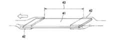
測定する不織布のシートから、弾性率を測定する方向を長手方向として縦150mm横50mmの試験体として切り出す(図4参照)。この試験体41の長手方向の両端にチャック42を取り付け、両チャック42間の距離43が100mmとなるようにする。片側のチャックを固定し、もう一方のチャックを引張り、試験体41を伸長させながら、試験体の伸びと荷重の値を断続的に測定する。得られた測定値をもとに、横軸に伸び(mm)、縦軸に荷重(N)をとりプロットし、伸びに対して荷重が直線的に変化する初期伸びに対する荷重の傾きを求める。この測定を10回行い前記傾きの平均値を求める。これを本発明における弾性率とする。
不織布シートから試験体を切り取る方向により弾性率が異なるときには、前述の第1層の不織布を伸長する方向の弾性率をいうものとし、第1層を複数の方向で伸長するときにはこれらの平均値をいうものとする。[Measurement and calculation method of elastic modulus of nonwoven fabric]
From the nonwoven fabric sheet to be measured, a test body having a length of 150 mm and a width of 50 mm is cut out with the direction in which the elastic modulus is measured as the longitudinal direction (see FIG. 4). The
When the modulus of elasticity varies depending on the direction in which the specimen is cut from the nonwoven fabric sheet, it refers to the modulus of elasticity in the direction in which the nonwoven fabric of the first layer is stretched, and when the first layer is stretched in a plurality of directions, the average value thereof is It shall be said.
第1層の不織布として用いることのできる材料は特に限定されないが、熱接着や接着剤による接合等のボンディング工程を経た製品不織布や、これらのボンディング工程を経ていないいわゆる不織ウエブも含まれる。用いられる繊維は特に限定されないが、ポリプロピレン(PP)、ポリエチレン(PE)、ポリエチレンテレフタレート(PET)、これらの複合繊維、アクリル系繊維、セルロース系繊維が挙げられ、中でもPP、PE、PETの複合繊維が好ましく用いられる。不織布の製造方法は特に限定はなく、例えば、スパンボンド、スパンレース、エアスルー、ポイントボンド、メルトブロー、ケミカルボンド、エアレイド、ニードルパンチ等の方法にて製造することができる。中でも、本発明の第1層に用いる不織布としては、弾性変形による伸長をさせ弛緩して適度に収縮することを考慮し、スパンボンド、エアスルー、ケミカルボンド、スパンレースによる不織布が好ましい。 The material that can be used as the nonwoven fabric of the first layer is not particularly limited, and includes a product nonwoven fabric that has undergone a bonding process such as thermal bonding or bonding with an adhesive, and a so-called nonwoven web that has not undergone these bonding processes. The fiber used is not particularly limited, and examples thereof include polypropylene (PP), polyethylene (PE), polyethylene terephthalate (PET), these composite fibers, acrylic fibers, and cellulosic fibers, among which PP, PE, and PET composite fibers. Is preferably used. The method for producing the nonwoven fabric is not particularly limited. For example, the nonwoven fabric can be produced by a method such as spun bond, spun lace, air through, point bond, melt blow, chemical bond, air laid, needle punch. Among them, the nonwoven fabric used for the first layer of the present invention is preferably a nonwoven fabric made of spunbond, air-through, chemical bond, or spunlace in consideration of elongation by elastic deformation, relaxation, and appropriate shrinkage.
第1層の不織布の坪量は特に限定されないが、12〜40g/m2であることが好ましく、15〜30g/m2であることがより好ましい。第1層の不織布の厚さは特に限定されないが、0.1〜1.0mmであることが好ましく、0.15〜0.8mmであることがより好ましい。本発明において不織布の厚さは、特に断らない限り、レーザー変位計(KEYENCE(株)社製 LK−085)を用い、50Paの荷重をかけた条件で測定した厚みをいう。この測定は、10回行いその平均値をその不織布の厚みとする。Is not particularly limited basis weight of the nonwoven fabric of the first layer is preferably 12~40g /m 2, and more preferably 15 to 30 g /m 2. Although the thickness of the nonwoven fabric of a 1st layer is not specifically limited, It is preferable that it is 0.1-1.0 mm, and it is more preferable that it is 0.15-0.8 mm. In the present invention, unless otherwise specified, the thickness of the nonwoven fabric refers to a thickness measured using a laser displacement meter (LK-085 manufactured by KEYENCE Corp.) under a load of 50 Pa. This measurement is performed 10 times, and the average value is taken as the thickness of the nonwoven fabric.
本発明の製造方法においては、実質的に非伸長の不織布からなる第2層が、上記第1層と組み合わせて用いられる。この第2層に用いられる不織布は通常のものであれば特に限定されず、上記第1層で例示した繊維ないし製造方法を用いたものが挙げられる。なかでも、上記第2層は上述したように柔らかに波打った多数の嵩のある領域が設けられ嵩高い不織布構造をなすことが好ましく、これを通常着用者の肌に当接して用いることに鑑み、第2層の不織布を構成する繊維を芯鞘型複合繊維、5.6dtex以下の低繊度、とすることが好ましく、製造方法はエアスルー、ポイントボンド、スパンレースによるものであることが好ましい。 In the production method of the present invention, a second layer made of a substantially non-stretched nonwoven fabric is used in combination with the first layer. If the nonwoven fabric used for this 2nd layer is a normal thing, it will not specifically limit, The thing using the fiber thru | or the manufacturing method illustrated by the said 1st layer is mentioned. Among these, the second layer preferably has a bulky nonwoven structure provided with a number of bulky areas that are softly undulated as described above, and is usually used in contact with the skin of the wearer. In view of the above, it is preferable that the fibers constituting the second layer nonwoven fabric have a core-sheath type composite fiber and a low fineness of 5.6 dtex or less, and the manufacturing method is preferably air-through, point bond, or spunlace.
第2層の不織布の坪量は特に限定されないが、16〜50g/m2であることが好ましく、18〜35g/m2であることがより好ましい。第2層の不織布の厚さは特に限定されないが、0.4〜1.5mmであることが好ましく、0.5〜1.2mmであることがより好ましい。
また、上記第2層の座屈荷重を20cN以下とすることが好ましく、15cN以下とすることがより好ましい。このようにすることで、上記第1層と間欠的に接合し、この第1層の伸長・弛緩の動きにあわせて第2層に嵩のある領域が形成されやすくなり、一層良好なクッション性が実現される。But the basis weight of the nonwoven fabric of the second layer is not particularly limited, is preferably 16~50g /m 2, and more preferably 18~35g /m 2. The thickness of the nonwoven fabric of the second layer is not particularly limited, but is preferably 0.4 to 1.5 mm, and more preferably 0.5 to 1.2 mm.
Further, the buckling load of the second layer is preferably 20 cN or less, and more preferably 15 cN or less. By doing so, the first layer is intermittently joined, and it becomes easy to form a bulky region in the second layer in accordance with the extension / relaxation movement of the first layer, so that the cushioning property is further improved. Is realized.
[座屈荷重の測定方法]
本発明において上記座屈荷重とは以下のようにして測定した値をいう。
まず、測定対象となる不織布のシートから、座屈荷重を測定する方向と直交する方向を長手方向にして、150mm×30mmの試験体を切り出す。この試験体の長手方向の両側縁が円筒の両縁をなすよう、前記試験体を円筒状に丸める。該長手方向の両端部が約5mm重なるようにして、ステープラー針54で2箇所をとめる(図5参照)。作製した円筒状の試験体51の、片方の縁が接するように水平のステージ52にのせ、もう一方の縁に水平の加圧板53をあてる。加圧板を10mm/minの速度で押し下げていったとき、試験体51が変形していく際に加圧板にかけられた最大点荷重を求める。同様の測定を1つの試験材あたり5回行い、平均値を求め、本発明における座屈荷重とする。なお、測定する第2層の不織布が、不織布シートから試験材を切り取る方向により異なる座屈荷重を有するときは、前記第1層を伸長させる方向に対応する第2層の不織布の方向の座屈荷重をいうものとする。第1層を複数の方向で伸長するときには、これらに対応する方向の平均値をいうものとする。[Measurement method of buckling load]
In the present invention, the buckling load refers to a value measured as follows.
First, a 150 mm × 30 mm specimen is cut out from the nonwoven fabric sheet to be measured with the direction perpendicular to the direction in which the buckling load is measured as the longitudinal direction. The test body is rolled into a cylindrical shape so that both side edges in the longitudinal direction of the test body form both edges of the cylinder. The two ends of the longitudinal direction are overlapped with each other by about 5 mm, and two places are stopped by the stapler needle 54 (see FIG. 5). The produced
本発明の製造方法で得られる嵩高不織布は、図示したパンティライナ以外にも、例えば、ナプキン、使い捨ておむつ、絆創膏を始めとした傷口シートなどの表面材として好適に用いることができる。 The bulky nonwoven fabric obtained by the production method of the present invention can be suitably used as a surface material for wound sheets such as napkins, disposable diapers, and adhesive bandages in addition to the illustrated panty liner.
以下、本発明を実施例に基づきさらに詳細に説明するが、本発明はこれにより限定して解釈されるものではない。
(実施例・比較例)
図1に示した製造工程により下記のようにして不織布複合材(試験材1〜5)を作製した。
原反ロール11から表1に示した第1層の不織布シート1を送りだし、一方原反ロール12から表1に示した第2層の不織布シート2を送り出した。第1層シート1についてはテンションロール14により下表1に示した伸長率となるようにした。135℃に加熱したエンボスロール17には千鳥格子状の円形エンボスが賦型されるように凸部18が配設され、上記両シート1,2をフラットロール16との間で間欠的に加熱圧着した。このようにして複数の円形エンボスにより接着した複合シート4をさらに送りだし、ガイドロール19を通過したところで上記第1層の伸長状態を解き弛緩し、不織布複合材(試験材1〜5)を得た。得られた試験材1〜5には図6に示したような千鳥格子状の円形エンボスが互いに均等な間隔で形成され、この最近接距離d1はいずれの試験材についてもおよそ4mmであり、円形エンボスの直径は2mmであった。
なお、試験材1の第1層に用いた不織布は伸長回復率が57%であり、試験材2及び3の第1層に用いた不織布の破断点伸度はそれぞれ25%及び22%であり、いずれもエラストマー的挙動を示さない不織布であった。EXAMPLES Hereinafter, although this invention is demonstrated further in detail based on an Example, this invention is limited to this and is not interpreted.
(Examples and comparative examples)
Nonwoven fabric composite materials (test materials 1 to 5) were produced as follows by the production process shown in FIG.
The first layer nonwoven fabric sheet 1 shown in Table 1 was fed out from the
The nonwoven fabric used for the first layer of the test material 1 has an elongation recovery rate of 57%, and the elongation at break of the nonwoven fabric used for the first layer of the
上記試験材1〜5の作製手順に対して、形成される接着領域が図7に示したような連続した格子柄状になるようにエンボスロールを変更した以外同様にして、不織布複合材(試験材6)を得た。試験材6における接着領域71の幅wは1mmであり、格子間距離mは7mmであった。 In the same manner as for the preparation procedures for the above test materials 1 to 5, except that the embossing roll was changed so that the formed adhesion region became a continuous lattice pattern as shown in FIG. Material 6) was obtained. The width w of the
[嵩のある領域の有無及びクッション性のパネル試験]
作製した試験材1〜6について、第1層外側に形成された嵩のある領域の有無及びこのクッション性をパネル5人による試験により評価した。評価の基準は以下のとおりである。はっきりと嵩のある領域が目視確認され、手触りにより高いクッション性が感じられるものを「◎」とした。嵩のある領域が見た目に認められるが際立った凹凸ではなく、手触りによるクッション性が幾分感じられるものを「○」とした。嵩のある領域が見た目にどうにか確認されるが、手触りによるクッション性はほとんど感じられないものを「△」とした。嵩のある領域が目視確認されず、手触りによるクッション性も全ったく感じられないものを「×」とした。結果を下表1に示した。[Existence of bulky area and cushioning panel test]
About the produced test materials 1-6, the presence or absence of the bulky area | region formed in the 1st layer outer side and this cushioning property were evaluated by the test by five panels. The criteria for evaluation are as follows. A clearly bulky area was visually confirmed, and a high cushioning feeling was felt when touched. “◯” indicates that a bulky region is visually recognized but not a conspicuous unevenness, and the cushioning property by touch is somewhat felt. A case where the bulky area was confirmed visually, but the cushioning property due to the touch was hardly felt was designated as “Δ”. A case where the bulky region was not visually confirmed and the cushioning property by touch was not felt at all was designated as “x”. The results are shown in Table 1 below.
[試験材の厚さの測定]
作製した試験材1〜6について、それぞれ、レーザー変位計(KEYENCE(株)社製 LK−085)を用いて、円板状の重り(直径60mm 重量14.0g:50Pa)を測定台に載せ、その時の厚みを0とし、次に100×100mmのサイズに切り出した試験片を測定台に載せ、その上に重りを載せた際の測定値を試験片の厚みとした。この測定を別々の試験片にて10回行い、その測定値の平均をそれぞれの試験材の厚みとした。このようにして厚さ(t1)を測定した。結果を下表1に示した。[Measurement of test material thickness]
About each of the produced test materials 1 to 6, using a laser displacement meter (LK-085 manufactured by KEYENCE Inc.), a disk-like weight (diameter 60 mm, weight 14.0 g: 50 Pa) is placed on a measurement table, The thickness at that time was set to 0, and then a test piece cut out to a size of 100 × 100 mm was placed on a measurement table, and the measured value when a weight was placed thereon was taken as the thickness of the test piece. This measurement was performed 10 times on separate test pieces, and the average of the measured values was taken as the thickness of each test material. Thus, the thickness (t1 ) was measured. The results are shown in Table 1 below.
[厚さ変化率の算出]
各試験材の作製に用いた第1層不織布と第2層不織布とを加工せず、そのまま重ね合わせたものについて、上述の試験材の厚さの測定と同様にして厚さ(t2)を測定した。この重ね合わせただけのものの厚さをt2とし、上述の試験材の厚さt1との比率(t1/t2)を求めて、厚さ変化率とした。結果を下表1に示した。[Calculation of thickness change rate]
The first layer nonwoven fabric and the second layer nonwoven fabric used for the preparation of each test material were not processed, and the thickness (t2 ) was measured in the same manner as the measurement of the thickness of the test material described above. It was measured. The thickness of the superposed one was t2 , and the ratio (t1 / t2 ) with the above-described thickness t1 of the test material was obtained to obtain the thickness change rate. The results are shown in Table 1 below.

比較のための試験材4〜6はいずれも単に不織布を重ね合わせたものより厚みが増すことはなく、エンボスパターンが連続したもの(試験材6)はむしろ薄いものとなってしまった。また、これらの試験材には嵩のある領域が認められず、いずれもクッション性のないものであった(パネル試験の判定「×」)。
これに対し、本発明の製造方法により製造した試験材1〜3はいずれも厚みが増し嵩高くなり、良好な嵩のある領域が多数形成され、クッション性に富む柔らかな風合いのものであった。なかでも、試験材1及び2は厚さ変化率がそれぞれ50%及び27%という、エラストマー材料を用いていないにも関わらず顕著な厚みの増加がみられ、極めて高いクッション性を感じられるものであった。これらの結果から、本発明の製造方法によれば、複数の嵩のある領域及びその内部に保持された空間によるクッション性に富む良質の嵩高不織布を、高コストのエラストマー材料によらず、かつ複雑な加工工程や特殊な加工装置を用いずに、効率的かつ低コストで製造することができることが分かる。The test materials 4 to 6 for comparison did not increase in thickness as compared with the case where the nonwoven fabrics were simply overlapped, and the test material 6 having a continuous emboss pattern (test material 6) was rather thin. In addition, no bulky area was observed in these test materials, and none of them had cushioning properties (judgment of panel test “x”).
On the other hand, all of the test materials 1 to 3 manufactured by the manufacturing method of the present invention are thick and bulky, a large number of good bulk regions are formed, and they have a soft texture rich in cushioning properties. . In particular, the test materials 1 and 2 have a thickness change rate of 50% and 27%, respectively, and a remarkable increase in thickness is observed despite the fact that no elastomer material is used. there were. From these results, according to the production method of the present invention, a high-quality bulky nonwoven fabric having a high cushioning property due to a plurality of bulky regions and spaces held in the plurality of bulky regions and a high-cost elastomeric material can be obtained. It can be seen that it can be manufactured efficiently and at low cost without using a complicated processing step or a special processing apparatus.
1 第1層の不織布シート
2 第2層の不織布シート
3 接着領域(円形エンボス)
4 嵩のある領域(丘状部)
5 空間
7 伸長領域
8 弛緩領域
9 複合シート
10 嵩高不織布
11、12 原反ロール
13、19 ガイドロール
14 テンションロール
16 フラットロール
17 エンボスロール
18 凸部
31 サイドシール部
32 吸収体
33 裏面シート
41、51 試験体
42 チャック
52 ステージ
53 加圧板
54 ステープラー針
71 連続接着領域DESCRIPTION OF SYMBOLS 1 Nonwoven sheet of 1st layer 2 Nonwoven sheet of
4 Bulky area (hill-shaped part)
DESCRIPTION OF SYMBOLS 5 Space 7 Elongation area | region 8 Relaxation area | region 9
Claims (5)
Translated fromJapanese(b)前記第1層と、不織布からなる第2層を実質的に非伸長の状態で積層させる工程、
(c)前記第1層の伸長状態を維持して、複数の接着領域がそれぞれ不連続になるように前記第1層と第2層とを接着する工程、及び
(d)前記接着した両層を弛緩させ第2層の外側面に複数の嵩のある領域を生じさせる工程を有する不織布の製造方法。(A) a step of causing at least 2% elongation of the first layer made of a non-woven fabric not exhibiting elastomeric behavior to cause elastic deformation;
(B) a step of laminating the first layer and the second layer made of a nonwoven fabric in a substantially non-stretched state;
(C) maintaining the stretched state of the first layer and bonding the first layer and the second layer such that a plurality of bonded regions are discontinuous, and (d) the bonded layers A method for producing a non-woven fabric, comprising a step of relaxing the substrate to form a plurality of bulky regions on the outer surface of the second layer.
さらに前記複数の接着領域の合計面積(s1)と、嵩高不織布全体の面積(s2)との割合(s1/s2)を10%以下とすることを特徴とする請求項1又は2記載の不織布の製造方法。The area of each of the plurality of adhesion regions is 5 mm or less in equivalent circle diameter, and the closest distance of the plurality of adhesion regions in the extending direction of the first layer is 3 to 20 mm,
Further, the ratio (s1 / s2) of the total area (s1) of the plurality of adhesion regions and the area (s2) of the entire bulky nonwoven fabric is 10% or less, The nonwoven fabric according to claim 1 or 2, Production method.
Priority Applications (1)
| Application Number | Priority Date | Filing Date | Title |
|---|---|---|---|
| JP2007276987AJP2009102774A (en) | 2007-10-24 | 2007-10-24 | Nonwoven manufacturing method |
Applications Claiming Priority (1)
| Application Number | Priority Date | Filing Date | Title |
|---|---|---|---|
| JP2007276987AJP2009102774A (en) | 2007-10-24 | 2007-10-24 | Nonwoven manufacturing method |
Publications (1)
| Publication Number | Publication Date |
|---|---|
| JP2009102774Atrue JP2009102774A (en) | 2009-05-14 |
Family
ID=40704741
Family Applications (1)
| Application Number | Title | Priority Date | Filing Date |
|---|---|---|---|
| JP2007276987APendingJP2009102774A (en) | 2007-10-24 | 2007-10-24 | Nonwoven manufacturing method |
Country Status (1)
| Country | Link |
|---|---|
| JP (1) | JP2009102774A (en) |
Cited By (2)
| Publication number | Priority date | Publication date | Assignee | Title |
|---|---|---|---|---|
| JP2013169388A (en)* | 2012-02-22 | 2013-09-02 | Oji Nepia Co Ltd | Absorbent article and method for manufacturing the same |
| WO2014024643A1 (en)* | 2012-08-08 | 2014-02-13 | 花王株式会社 | Composite sheet manufacturing method |
Citations (2)
| Publication number | Priority date | Publication date | Assignee | Title |
|---|---|---|---|---|
| JPH06255006A (en)* | 1992-12-29 | 1994-09-13 | Kimberly Clark Corp | High-bulk laminated material provided with pillow part by stretching and its production |
| JP2004000465A (en)* | 2002-03-22 | 2004-01-08 | Kao Corp | Absorbent articles |
- 2007
- 2007-10-24JPJP2007276987Apatent/JP2009102774A/enactivePending
Patent Citations (2)
| Publication number | Priority date | Publication date | Assignee | Title |
|---|---|---|---|---|
| JPH06255006A (en)* | 1992-12-29 | 1994-09-13 | Kimberly Clark Corp | High-bulk laminated material provided with pillow part by stretching and its production |
| JP2004000465A (en)* | 2002-03-22 | 2004-01-08 | Kao Corp | Absorbent articles |
Cited By (6)
| Publication number | Priority date | Publication date | Assignee | Title |
|---|---|---|---|---|
| JP2013169388A (en)* | 2012-02-22 | 2013-09-02 | Oji Nepia Co Ltd | Absorbent article and method for manufacturing the same |
| WO2014024643A1 (en)* | 2012-08-08 | 2014-02-13 | 花王株式会社 | Composite sheet manufacturing method |
| JP2014034145A (en)* | 2012-08-08 | 2014-02-24 | Kao Corp | Production method of composite sheet |
| CN104602903A (en)* | 2012-08-08 | 2015-05-06 | 花王株式会社 | Composite sheet manufacturing method |
| CN104602903B (en)* | 2012-08-08 | 2016-10-12 | 花王株式会社 | Composite sheet manufacturing method |
| RU2635153C2 (en)* | 2012-08-08 | 2017-11-09 | Као Корпорейшн | Method for producing composite sheet |
Similar Documents
| Publication | Publication Date | Title |
|---|---|---|
| AU2007326553B2 (en) | Composite sheet and absorbent article comprising composite sheet | |
| CN101166858B (en) | Stretchable sheet and its manufacturing method | |
| KR100249640B1 (en) | Stretch-pillowed, bulked laminate | |
| JP3883530B2 (en) | Composite elastic member and manufacturing method thereof | |
| JP5100359B2 (en) | Stretchable composite sheet and manufacturing method thereof | |
| JP4508885B2 (en) | Absorbent articles | |
| JP4827597B2 (en) | Elastic sheet and method for producing the same | |
| KR20090034872A (en) | Disposable diaper using sheet member, manufacturing method of high density region containing sheet and sheet member | |
| WO2006115259A1 (en) | Stretch sheet and process for producing the same | |
| WO2013161983A1 (en) | Composite sheet and method for manufacturing composite sheet | |
| JP4535771B2 (en) | Composite elastic member and manufacturing method thereof | |
| EP1066961B1 (en) | Process for making elastically stretchable composite sheet | |
| JP5367961B2 (en) | Disposable diaper, sheet member and method for producing pleated sheet | |
| US8183429B2 (en) | Composite sheet and absorbent article comprising composite sheet | |
| JP2008030468A (en) | Sheet member, method for manufacturing sheet including high-density region and disposable diaper using the sheet member | |
| JP2007014802A (en) | Absorbent articles | |
| JP6396549B1 (en) | Disposable wearing items | |
| JP6276971B2 (en) | Composite stretchable sheet and manufacturing method thereof | |
| JP2019115409A (en) | Stretchable sheet, and absorbent article including the same | |
| JP2020092744A (en) | Absorbent article having composite stretch sheet | |
| JP5060281B2 (en) | Absorbent articles | |
| JP2009102774A (en) | Nonwoven manufacturing method | |
| WO2017122645A1 (en) | Disposable article and method for manufacturing disposable article | |
| WO2018189780A1 (en) | Composite stretch member and disposable diaper provided with same | |
| KR20180089392A (en) | Disposable sheet and method of manufacturing disposable sheet |
Legal Events
| Date | Code | Title | Description |
|---|---|---|---|
| A621 | Written request for application examination | Free format text:JAPANESE INTERMEDIATE CODE: A621 Effective date:20100917 | |
| A977 | Report on retrieval | Free format text:JAPANESE INTERMEDIATE CODE: A971007 Effective date:20120127 | |
| A131 | Notification of reasons for refusal | Free format text:JAPANESE INTERMEDIATE CODE: A131 Effective date:20120214 | |
| A521 | Written amendment | Free format text:JAPANESE INTERMEDIATE CODE: A523 Effective date:20120416 Free format text:JAPANESE INTERMEDIATE CODE: A821 Effective date:20120416 | |
| RD03 | Notification of appointment of power of attorney | Free format text:JAPANESE INTERMEDIATE CODE: A7423 Effective date:20120416 | |
| A131 | Notification of reasons for refusal | Free format text:JAPANESE INTERMEDIATE CODE: A131 Effective date:20120724 | |
| A02 | Decision of refusal | Free format text:JAPANESE INTERMEDIATE CODE: A02 Effective date:20121204 |