JP2009097882A - Device for measuring amount of insulated heat - Google Patents
Device for measuring amount of insulated heatDownload PDFInfo
- Publication number
- JP2009097882A JP2009097882AJP2007266895AJP2007266895AJP2009097882AJP 2009097882 AJP2009097882 AJP 2009097882AJP 2007266895 AJP2007266895 AJP 2007266895AJP 2007266895 AJP2007266895 AJP 2007266895AJP 2009097882 AJP2009097882 AJP 2009097882A
- Authority
- JP
- Japan
- Prior art keywords
- temperature
- thermostat
- sample
- circulating fluid
- pipe
- Prior art date
- Legal status (The legal status is an assumption and is not a legal conclusion. Google has not performed a legal analysis and makes no representation as to the accuracy of the status listed.)
- Pending
Links
- 239000012530fluidSubstances0.000claimsdescription35
- 238000010438heat treatmentMethods0.000claimsdescription17
- 238000009413insulationMethods0.000abstractdescription8
- 239000007788liquidSubstances0.000abstractdescription8
- 238000005259measurementMethods0.000description7
- 238000010586diagramMethods0.000description4
- BASFCYQUMIYNBI-UHFFFAOYSA-NplatinumChemical compound[Pt]BASFCYQUMIYNBI-UHFFFAOYSA-N0.000description4
- 239000011810insulating materialSubstances0.000description3
- 239000003507refrigerantSubstances0.000description3
- 238000003756stirringMethods0.000description3
- 239000000919ceramicSubstances0.000description2
- 238000006243chemical reactionMethods0.000description2
- 238000010292electrical insulationMethods0.000description2
- 239000000463materialSubstances0.000description2
- 229910052697platinumInorganic materials0.000description2
- 229910001006ConstantanInorganic materials0.000description1
- 239000004743PolypropyleneSubstances0.000description1
- 238000013019agitationMethods0.000description1
- 230000002528anti-freezeEffects0.000description1
- 238000013459approachMethods0.000description1
- 230000001174ascending effectEffects0.000description1
- 238000009529body temperature measurementMethods0.000description1
- 239000011449brickSubstances0.000description1
- 238000001816coolingMethods0.000description1
- 230000007423decreaseEffects0.000description1
- 239000000835fiberSubstances0.000description1
- 230000009970fire resistant effectEffects0.000description1
- 230000007774longtermEffects0.000description1
- 239000000203mixtureSubstances0.000description1
- 238000012986modificationMethods0.000description1
- 230000004048modificationEffects0.000description1
- -1polypropylenePolymers0.000description1
- 229920001155polypropylenePolymers0.000description1
- 230000004044responseEffects0.000description1
- 230000004043responsivenessEffects0.000description1
- 239000000126substanceSubstances0.000description1
Images


Landscapes
- Investigating Or Analyzing Materials Using Thermal Means (AREA)
Abstract
Description
Translated fromJapaneseこの発明は、断熱熱量測定装置に関する。さらに詳しくは、試料の温度上昇に追従して恒温槽内の温度制御を行う断熱熱量測定装置に関する。 The present invention relates to an adiabatic calorimeter. More specifically, the present invention relates to an adiabatic calorimeter that performs temperature control in a thermostatic chamber following the temperature rise of a sample.
物質が化学反応を行う時、発熱を伴い温度上昇する。この温度上昇により更に反応が促進し、温度上昇が進む。このような相乗作用により得られた温度上昇曲線を計測し、解析を行うことにより必要な知見を得ることができる。以上のような測定を高い精度で行うためには、完全断熱に近い断熱温度制御が不可欠であり、測定手段として、断熱熱量計が用いられている。 When a substance undergoes a chemical reaction, the temperature rises with an exotherm. This temperature increase further promotes the reaction, and the temperature rise proceeds. Necessary knowledge can be obtained by measuring and analyzing the temperature rise curve obtained by such synergism. In order to perform the above measurement with high accuracy, adiabatic temperature control close to complete adiabatic is indispensable, and an adiabatic calorimeter is used as a measuring means.
断熱熱量計では、恒温槽内に断熱容器を格納し、その容器内で試料による温度上昇が発生したとき、容器内の温度と恒温槽内との温度差がかぎりなくゼロに接近するように温度上昇制御を行って、断熱容器内の試料の温度変化を測定し、熱量や温度上昇値などを求めることができる。 In an adiabatic calorimeter, when an insulated container is stored in a thermostatic chamber, and the temperature rises due to the sample in that container, the temperature is such that the temperature difference between the container and the thermostatic chamber approaches zero as much as possible. Ascending control can be performed to measure the temperature change of the sample in the heat insulating container, and to determine the amount of heat and the temperature rise value.
従来の断熱熱量計では、断熱温度上昇制御は、試料の温度と恒温槽内の温度との温度差を熱電対で検出して、試料の温度と恒温槽内の温度との温度差を打ち消すような制御を一段階で行う方式が採用されている。(例えば下記非特許文献1) In conventional adiabatic calorimeters, the adiabatic temperature rise control detects the temperature difference between the sample temperature and the temperature in the thermostat using a thermocouple, and cancels the temperature difference between the sample temperature and the temperature in the thermostat. A system that performs simple control in one step is adopted. (For example, the following non-patent document 1)
しかしながら、従来の断熱熱量計では、室温に対して恒温槽内の温度が高くなり、恒温槽内の温度と外部の温度との温度差が大きくなると、恒温槽内から外部に流出する熱量が大きくなってしまう。流出する熱量を補うためには、加熱用のヒータへの電力供給を大きくする必要があるが、そのためには、試料と恒温槽内との温度差が大きくなる必要がある。試料と恒温槽内との温度差が大きくなると、試料から恒温槽内に熱が流出するので、断熱精度が低下する問題が生じてしまう。 However, in the conventional adiabatic calorimeter, when the temperature in the thermostat is higher than the room temperature, and the temperature difference between the temperature in the thermostat and the external temperature is large, the amount of heat flowing out from the thermostat is large. turn into. In order to make up for the amount of heat that flows out, it is necessary to increase the power supply to the heater for heating. For this purpose, the temperature difference between the sample and the thermostat must be increased. If the temperature difference between the sample and the thermostat increases, heat flows from the sample into the thermostat, which causes a problem that the heat insulation accuracy decreases.
したがって、この発明の目的は、より精度の高い断熱精度を可能にする断熱熱量測定装置を提供することにある。 Accordingly, an object of the present invention is to provide an adiabatic calorimeter that enables a more accurate adiabatic accuracy.
上述した課題を解決するために、この発明は、
試料を入れる恒温槽と、
恒温槽内に配置され、恒温槽内の温度を調整する第1の加熱手段と、
恒温槽内に配置された管内を流通する循環液の温度を調整することにより、管を介して恒温槽内の温度を調整する第2の加熱手段と、
恒温槽内の温度と試料の温度との温度差を検出する第1の温度検出手段と、
循環液と恒温槽内の温度との温度差を検出する第2の温度検出手段と、
を備え、
第1の加熱手段により、第1の温度検出手段が検出する温度差を打ち消すように温度制御し、
第2の加熱手段により、第2の温度検出手段が検出する温度差を打ち消すように温度制御すること
を特徴とする断熱熱量測定装置である。In order to solve the above-described problems, the present invention provides:
A thermostatic chamber for the sample,
A first heating means arranged in the thermostat and adjusting the temperature in the thermostat;
A second heating means for adjusting the temperature in the thermostat through the pipe by adjusting the temperature of the circulating fluid flowing in the pipe arranged in the thermostat;
First temperature detecting means for detecting a temperature difference between the temperature in the thermostat and the temperature of the sample;
A second temperature detecting means for detecting a temperature difference between the circulating fluid and the temperature in the thermostat;
With
The first heating means controls the temperature so as to cancel the temperature difference detected by the first temperature detecting means,
The adiabatic calorimeter is characterized in that the temperature is controlled by the second heating means so as to cancel out the temperature difference detected by the second temperature detecting means.
この発明では、第1の加熱手段により、第1の温度検出手段が検出する恒温槽内の温度と試料の温度との温度差を打ち消すように温度制御し、第2の加熱手段により、第2の温度検出手段が検出する循環液と恒温槽内の温度との温度差を打ち消すように温度制御する。これにより、試料の温度上昇に追従する温度制御を行うと同時に、恒温槽内の温度に追従した循環液を恒温槽内に流通させ、恒温槽内から流出する熱量を補うようにすることで、より精度の高い断熱精度を実現可能とする。 In the present invention, the temperature is controlled by the first heating means so as to cancel the temperature difference between the temperature in the thermostatic chamber detected by the first temperature detecting means and the temperature of the sample, and the second heating means The temperature is controlled so as to cancel out the temperature difference between the circulating fluid detected by the temperature detecting means and the temperature in the thermostatic chamber. Thereby, while performing temperature control following the temperature rise of the sample, circulating the circulating fluid following the temperature in the thermostatic bath in the thermostatic bath, so as to compensate for the amount of heat flowing out of the thermostatic bath, Higher heat insulation accuracy can be realized.
この発明によれば、より高い断熱精度を有する断熱熱量測定装置を提供できる。 According to the present invention, an adiabatic calorimeter having higher insulation accuracy can be provided.
以下、この発明の実施の形態について図面を参照して説明する。図1は、この発明の一実施形態による断熱熱量測定装置の構成を表す全体構成図である。この断熱熱量測定装置は、例えば、マスコンクリートの断熱温度上昇測定などに用いられるものである。 Embodiments of the present invention will be described below with reference to the drawings. FIG. 1 is an overall configuration diagram showing the configuration of an adiabatic calorimeter according to an embodiment of the present invention. This adiabatic calorimeter is used, for example, for measuring adiabatic temperature rise of mass concrete.
図1に示すように、この発明の一実施形態による断熱熱量測定装置は、主として、測定対象となる試料10を入れる恒温槽1と、ヒータ2a〜2bと、パイプ3と、熱電対4a〜4bと、ファン5とから構成されており、熱電対4aが検出する試料10の温度と恒温槽1内の温度との温度差を打ち消すような温度制御と、熱電対4bが検出する恒温槽1内の温度と循環液との温度差を打ち消すような温度制御との二重制御で温度制御がなされるものである。 As shown in FIG. 1, the adiabatic calorimeter according to one embodiment of the present invention mainly includes a
恒温槽1は、断熱材6よりなる筐体であり、外部と熱的に遮断された空間を有する。断熱材6は、測定温度範囲に応じて材料および材質が選ばれ、一般に形状が複雑な部分や、重量による圧力が掛からない部分には、例えば柔軟性のあるセラミックスファイバなどを用いることができる。断熱と電気絶縁を兼ねて一旦固定したら動かないことを目的とする部分には、例えばセラミックフェルトウェットなどを用いることができる。その他、形状が単純で重量や圧力が掛かる部分には、例えば高温耐火断熱レンガなどを用いることができる。恒温槽1内には、測定対象となる試料10が配置されている。試料10は、例えば図示しない試料容器に入れられている。試料容器としては、特に限定されないが、例えばポリプロピレン製のボトルなどを用いることができる。 The
ヒータ2aは、恒温槽1内を加熱して、恒温槽1内の温度を試料10の温度上昇に追従してコントロールするためのものである。ヒータ2bは、循環液を加熱して、循環液の温度を恒温槽1内の温度上昇に追従してコントロールするためのものである。ヒータ2a〜2bとしては、例えば、熱容量が小さく応答性の良いシースヒータなどを用いることができる。 The
パイプ3は、その内部に、例えば不凍液などの循環液が流通する管であり、恒温槽1内のヒータ2aの下側に、捲回された状態で配置され、恒温槽1の外部に配置された循環液温度調整部16に連通している。 The pipe 3 is a pipe through which a circulating fluid such as an antifreeze liquid is circulated. The pipe 3 is disposed below the
液体循環ポンプ15により、循環液を流動させ、循環液をパイプ3(恒温槽1内)→パイプ3(恒温槽1外)→循環液温度調整部16→パイプ3(恒温槽1外)→パイプ3(恒温槽1内)の順に循環する。 The circulating fluid is caused to flow by the
循環液の温度を調整することで、パイプ3を介して、恒温槽1内の温度を制御することができる。例えば、循環液の温度を試料10の温度上昇に追従するようにして、恒温槽1内の温度を補完的に制御したり、試料10の測定開始温度を室温以下に設定する場合に、室温より低い循環液を循環させるようにして、恒温槽1内を室温以下に制御したりする。 By adjusting the temperature of the circulating fluid, the temperature in the
循環液温度調整部16は、ヒータ2bと、ヒータ2bの周囲を巻回するパイプ9とを有し、ヒータ2bとパイプ9とによって、循環液の温度調整を行う。ヒータ2bは、循環液を加熱するためのものでり、パイプ9は、循環液を冷却するためのものである。パイプ9の内部には、冷凍機8に冷却された冷媒が循環しており、この冷媒によって、パイプ9を介して循環液を冷却する。 The circulating fluid
熱電対4aは、試料10を基準にして恒温槽1内の温度を限りなく試料と同一温度に制御するために、試料10と恒温槽1内との温度差を検出するものであり、応答性に優れていて、電気的には、絶縁されている。試料10側の熱電対4aは、試料10内に挿入されていて、恒温槽1側の熱電対4aは、恒温槽1内の所定位置に配置されている。 The
熱電対4bは、恒温槽1内の温度を基準にして、循環液の温度を限りなく恒温槽1内と同一温度に制御するために、循環液と恒温槽1との温度差を検出するものであり、応答性に優れていて、電気的には、絶縁されている。恒温槽1側の熱電対4bは、恒温槽1内の所定位置に配置されている。循環液側の熱電対4bは、恒温槽1外のパイプ3内の所定位置に配置されている。熱電対4a〜4bとしては、例えば、銅−コンスタンタン熱電対などを用いることができる。 The
ファン5は、恒温槽1内の温度が試料10の温度と異なったり、恒温槽1内に温度分布が生じたりすると、長期間の測定を行うとき精度に影響を及ぼすため、恒温槽1内の空気を攪拌するために設けられるものである。モータ7は、ファン5を駆動するためのものである。モータ7は、恒温槽1外に取り付けてあり、モータ7の発熱が恒温槽1内に影響を及ぼさないように断熱されている。 If the temperature in the
恒温槽1は、図2に示すように、恒温槽1内の4隅に風道21を有する構造とされ、中段には、試料容器をのせる台22が取り付けられている。台22の中心部は、開口されており、その下にはファン5が設けられている。ヒータ2aは、ファン5の回転による風が満遍に当たる位置に固定されている。 As shown in FIG. 2, the
この構造を有する恒温槽1では、矢印Wで示した風の流れのように、ファン5の回転によって、台22の中心の開口部から吸い込まれた風が、ヒータ2aを経由して4隅の風道21を昇り、試料容器の全面を経由して再びファン5に戻る捩れを加えた立体攪拌が行われる。したがって、このような恒温槽1の構造では、恒温槽1内に温度分布が生じない。 In the
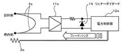
熱電対4aと、アンプ11aと、電力制御器12aと、ヒータ2aとから構成される回路では、図3に示すように、熱電対4aで差動検出した信号を直流増幅し、ツェナーダイオード14を経由してヒータ2aにフィードバックする。アンプ11aは、熱電対4aにより検出した信号を増幅するものである。電力制御器12aは、アンプ11aにより増幅された信号が入力され、入力された信号に応じて、ヒータ2bに供給する電力を制御するものである。また、熱電対4bと、電力制御器12bと、ヒータ2bとから構成される回路についても、上記と同様である。 In the circuit composed of the
また、恒温槽1内に設けられた白金測温抵抗体17などの測温抵抗体と、ヒータ2bと、温度調節器13とから構成される回路によって、例えば、所定の測定開始温度を設定するための制御が行われる。 Further, for example, a predetermined measurement start temperature is set by a circuit including a resistance temperature detector such as a platinum resistance temperature detector 17 provided in the
次に、断熱熱量測定装置の動作について説明する。まず、メインスイッチをONにすると、循環液を冷媒により冷却する冷凍機8、恒温槽1内を攪拌するモータ7などが駆動して、ファン5により、恒温槽1内の攪拌が開始される。 Next, the operation of the adiabatic calorimeter will be described. First, when the main switch is turned on, the refrigerator 8 that cools the circulating fluid with the refrigerant, the
スイッチS2AをP1側、スイッチS2BをP2側に切り替え、温度調節器13を目的の温度(例えば、20℃)に選び、温度制御を開始すると、ヒータ2bが駆動し、冷凍機8で冷却された低温の循環液が、ヒータ2bにより加熱される。そして、加熱された循環液がパイプ3(恒温槽1内)を流通することによって、恒温槽1内が所定の一定温度(例えば、20℃)に制御される。When the switch S2A is switched to the P1 side and the switch S2B is switched to the P2 side, the
恒温槽1内が一定温度になった後、恒温槽1内に、測定対象となる試料10を配置する。試料10を配置した後、スイッチS2AをM1側、スイッチS2BをM2側に切り替え、スイッチS1をONにすると、二重断熱温度制御を開始する。After the inside of the
スイッチS1をONにすると、アンプ11aおよび電力制御器12aの作動により、試料10と恒温槽1内とに配置された熱電対4aが検出した温度差を打ち消すように、ヒータ2bに対してフィードバック制御が行われ、試料10の温度を基準とした断熱制御を開始する。 When the switch S1 is turned ON, feedback control is performed on the heater 2b so that the temperature difference detected by the
スイッチS2AをM1側に切り替え、スイッチS2BをM2側に切り替えると、アンプ11bおよび電力制御器12bの作動により、恒温槽1内と循環液が流動するパイプ3内とに配置された熱電対4bが検出した温度差を打ち消すようにヒータ2bに対してフィードバック制御が行われ、循環液の温度制御を開始する。When the switch S2A is switched to the M1 side and the switch S2B is switched to the M2 side, the operation of the
また、試料10の温度上昇が所定温度(例えば45℃)に到達すると、サーマルスイッチTS1の作動により、冷凍機8は停止する。この目的は、45℃になると循環液を冷却する必要が無くなることおよび冷凍機8を保護するためである。冷凍機8の停止後は、ヒータ2bの加熱のみで、循環液の温度制御が継続してなされる。 When the temperature rise of the
以上の動作による温度制御がなされると、恒温槽1内および試料温度、並びに循環液の温度は、図4に示すような温度上昇曲線を示す。図4において、線d1は、恒温槽1内および試料10の温度上昇曲線を示す。線d2は、循環液の温度上昇曲線を示す。時間t=(a)は、温度測定開始時であり、t=(b)は、試料温度の上昇開始時であり、t=(c)は、冷凍機8停止時である。 When the temperature control by the above operation is performed, the temperature in the
この断熱熱量測定装置では、温度上昇曲線d1、d2が示すように、試料10の温度上昇開始の時点から温度上昇終了まで、恒温槽1内の温度上昇に対して循環液の温度上昇は、0.5℃〜1℃の温度差で追従する。したがって、温度上昇開始から終了まで、ヒータ2aに供給される電力が極小になり、極めて高精度の断熱制御が可能である。 In this adiabatic calorimeter, as shown by the temperature rise curves d1 and d2, the temperature rise of the circulating fluid is 0 with respect to the temperature rise in the
以上説明したように、この発明の一実施形態による断熱熱量測定装置は、試料10の温度上昇に追従する温度制御を行うと同時に、恒温槽1内の温度に追従した液体を恒温槽1内に流通させ恒温槽1内から流失する熱量を補う二重断熱制御により、より精度の高い断熱温度上昇を実現できる。 As described above, the adiabatic calorimeter according to one embodiment of the present invention performs temperature control that follows the temperature rise of the
この発明は、上述したこの発明の実施形態に限定されるものでは無く、この発明の要旨を逸脱しない範囲内で様々な変形や応用が可能である。例えば、測定開始温度を室温以上とする場合には、冷凍機8およびパイプ9を削除した構成としてもよい。 The present invention is not limited to the above-described embodiments of the present invention, and various modifications and applications are possible without departing from the spirit of the present invention. For example, when the measurement start temperature is set to room temperature or higher, the refrigerator 8 and the pipe 9 may be omitted.
1・・・恒温槽
2a、2b・・・ヒータ
3・・・パイプ
4a、4b・・・熱電対
5・・・ファン
6・・・断熱材
7・・・モータ
8・・・冷凍機
9・・・パイプ
10・・・試料
11a、11b・・・アンプ
12a、12b・・・電力制御器
13・・・温度調節器
14・・・ツェナーダイオード
15・・・液体循環ポンプ
16・・・循環液温度調整部
17・・・白金測温抵抗体
21・・・風道
22・・・台
S1、S2A、S2B・・・スイッチ
TS1・・・サーマルスイッチDESCRIPTION OF
Claims (3)
Translated fromJapanese上記恒温槽内に配置され、上記恒温槽内の温度を調整する第1の加熱手段と、
上記恒温槽内に配置された管内を流通する循環液の温度を調整することにより、上記管を介して上記恒温槽内の温度を調整する第2の加熱手段と、
上記恒温槽内の温度と上記試料の温度との温度差を検出する第1の温度検出手段と、
上記循環液と上記恒温槽内の温度との温度差を検出する第2の温度検出手段と、
を備え、
上記第1の加熱手段により、上記第1の温度検出手段が検出する温度差を打ち消すように温度制御し、
上記第2の加熱手段により、上記第2の温度検出手段が検出する温度差を打ち消すように温度制御すること
を特徴とする断熱熱量測定装置。A thermostatic chamber for the sample,
A first heating means arranged in the thermostat and adjusting the temperature in the thermostat;
A second heating means for adjusting the temperature in the thermostatic bath through the pipe by adjusting the temperature of the circulating fluid flowing in the pipe disposed in the thermostatic bath;
First temperature detecting means for detecting a temperature difference between the temperature in the thermostat and the temperature of the sample;
A second temperature detecting means for detecting a temperature difference between the circulating fluid and the temperature in the thermostat;
With
The first heating means controls the temperature so as to cancel the temperature difference detected by the first temperature detecting means,
An adiabatic calorimeter having a temperature controlled by the second heating means so as to cancel out the temperature difference detected by the second temperature detecting means.
を特徴とする請求項1記載の断熱熱量測定装置。The adiabatic calorimeter according to claim 1, wherein the first heating means and the second heating means are heaters.
を特徴とする請求項1記載の断熱熱量測定装置。The adiabatic calorimeter according to claim 1, wherein the first temperature detecting means and the second temperature detecting means are thermocouples.
Priority Applications (1)
| Application Number | Priority Date | Filing Date | Title |
|---|---|---|---|
| JP2007266895AJP2009097882A (en) | 2007-10-12 | 2007-10-12 | Device for measuring amount of insulated heat |
Applications Claiming Priority (1)
| Application Number | Priority Date | Filing Date | Title |
|---|---|---|---|
| JP2007266895AJP2009097882A (en) | 2007-10-12 | 2007-10-12 | Device for measuring amount of insulated heat |
Publications (1)
| Publication Number | Publication Date |
|---|---|
| JP2009097882Atrue JP2009097882A (en) | 2009-05-07 |
Family
ID=40701035
Family Applications (1)
| Application Number | Title | Priority Date | Filing Date |
|---|---|---|---|
| JP2007266895APendingJP2009097882A (en) | 2007-10-12 | 2007-10-12 | Device for measuring amount of insulated heat |
Country Status (1)
| Country | Link |
|---|---|
| JP (1) | JP2009097882A (en) |
Cited By (2)
| Publication number | Priority date | Publication date | Assignee | Title |
|---|---|---|---|---|
| EP2363695A1 (en) | 2010-03-03 | 2011-09-07 | Sumitomo Rubber Industries, Ltd. | Apparatus, method and programm for vehicle mass estimation |
| CN105911090A (en)* | 2016-04-20 | 2016-08-31 | 河北世纪建筑材料设备检验有限公司 | Novel heat conductivity coefficient test apparatus and heat conductivity coefficient test method |
Citations (4)
| Publication number | Priority date | Publication date | Assignee | Title |
|---|---|---|---|---|
| JPS6165148A (en)* | 1984-08-31 | 1986-04-03 | アメリカン・サイアナミド・カンパニ− | Calorimeter |
| JPH01313746A (en)* | 1988-06-13 | 1989-12-19 | Chichibu Cement Co Ltd | Insulating temperature rise measuring instrument |
| JPH05289754A (en)* | 1992-04-14 | 1993-11-05 | Daiichi Kagaku:Kk | Dew condensation preventing method for constant temperature/humidity chamber |
| JP2003014674A (en)* | 2001-07-03 | 2003-01-15 | Sumitomo Chem Co Ltd | Control method of calorimeter installation atmosphere |
- 2007
- 2007-10-12JPJP2007266895Apatent/JP2009097882A/enactivePending
Patent Citations (4)
| Publication number | Priority date | Publication date | Assignee | Title |
|---|---|---|---|---|
| JPS6165148A (en)* | 1984-08-31 | 1986-04-03 | アメリカン・サイアナミド・カンパニ− | Calorimeter |
| JPH01313746A (en)* | 1988-06-13 | 1989-12-19 | Chichibu Cement Co Ltd | Insulating temperature rise measuring instrument |
| JPH05289754A (en)* | 1992-04-14 | 1993-11-05 | Daiichi Kagaku:Kk | Dew condensation preventing method for constant temperature/humidity chamber |
| JP2003014674A (en)* | 2001-07-03 | 2003-01-15 | Sumitomo Chem Co Ltd | Control method of calorimeter installation atmosphere |
Cited By (2)
| Publication number | Priority date | Publication date | Assignee | Title |
|---|---|---|---|---|
| EP2363695A1 (en) | 2010-03-03 | 2011-09-07 | Sumitomo Rubber Industries, Ltd. | Apparatus, method and programm for vehicle mass estimation |
| CN105911090A (en)* | 2016-04-20 | 2016-08-31 | 河北世纪建筑材料设备检验有限公司 | Novel heat conductivity coefficient test apparatus and heat conductivity coefficient test method |
Similar Documents
| Publication | Publication Date | Title |
|---|---|---|
| US8815601B2 (en) | Calorimeter and method for performing reaction calorimetry | |
| JP4579993B2 (en) | Differential scanning calorimeter (DSC) with temperature controlled furnace | |
| US7635092B2 (en) | Humidity-controlled chamber for a thermogravimetric instrument | |
| CN202052555U (en) | Constant temperature bath device | |
| EP2572252B1 (en) | Heating in material testing apparatus | |
| Ahmed et al. | Measurement of radial thermal conductivity of a cylinder using a time-varying heat flux method | |
| CN105562133A (en) | Constant temperature device of air bath | |
| US7048435B2 (en) | Humidity-controlled chamber for a thermogravimetric instrument | |
| JP2009097882A (en) | Device for measuring amount of insulated heat | |
| CN208999333U (en) | An outdoor cabinet heat transfer coefficient test system | |
| JP4821851B2 (en) | Temperature chamber | |
| CN204170745U (en) | A kind of air bath thermostat | |
| AU2012327835B2 (en) | Method and system for flow measurement | |
| KR101230492B1 (en) | System and method for controlling temperature in thermoelectric element evaluation apparatus | |
| JP7106073B2 (en) | Thermal conductivity measuring device and thermal conductivity measuring method | |
| Merlone et al. | A liquid bath for accurate temperature measurements | |
| JP2001017868A (en) | Thermostatic apparatus for test | |
| Correa et al. | Furnace for scientific research with temperature control using Peltier cells and a gas heat transference system: Design and building | |
| JP2013020471A (en) | Temperature controller and temperature control method | |
| JPH07294596A (en) | Temperature control method in constant-temperature bath for high-low-temperature handler | |
| KR100385577B1 (en) | Temperature control-test device and its temperature control mode using thermoelement | |
| RU2137098C1 (en) | Gear determining coefficient of heat transfer of heat- insulated surface | |
| JP3113272U (en) | Thermal analyzer | |
| JP2014163731A (en) | Constant temperature bath for chromatograph | |
| Lattimer et al. | Quantifying thermal boundary condition details using a hybrid heat flux gage |
Legal Events
| Date | Code | Title | Description |
|---|---|---|---|
| A621 | Written request for application examination | Effective date:20100728 Free format text:JAPANESE INTERMEDIATE CODE: A621 | |
| A977 | Report on retrieval | Free format text:JAPANESE INTERMEDIATE CODE: A971007 Effective date:20120117 | |
| A131 | Notification of reasons for refusal | Effective date:20120221 Free format text:JAPANESE INTERMEDIATE CODE: A131 | |
| A02 | Decision of refusal | Free format text:JAPANESE INTERMEDIATE CODE: A02 Effective date:20120619 |