JP2009097389A - Decompression equipment with energy recovery function - Google Patents
Decompression equipment with energy recovery functionDownload PDFInfo
- Publication number
- JP2009097389A JP2009097389AJP2007268356AJP2007268356AJP2009097389AJP 2009097389 AJP2009097389 AJP 2009097389AJP 2007268356 AJP2007268356 AJP 2007268356AJP 2007268356 AJP2007268356 AJP 2007268356AJP 2009097389 AJP2009097389 AJP 2009097389A
- Authority
- JP
- Japan
- Prior art keywords
- heater
- fuel gas
- expander
- prime mover
- rankine cycle
- Prior art date
- Legal status (The legal status is an assumption and is not a legal conclusion. Google has not performed a legal analysis and makes no representation as to the accuracy of the status listed.)
- Pending
Links
Images


Classifications
- Y—GENERAL TAGGING OF NEW TECHNOLOGICAL DEVELOPMENTS; GENERAL TAGGING OF CROSS-SECTIONAL TECHNOLOGIES SPANNING OVER SEVERAL SECTIONS OF THE IPC; TECHNICAL SUBJECTS COVERED BY FORMER USPC CROSS-REFERENCE ART COLLECTIONS [XRACs] AND DIGESTS
- Y02—TECHNOLOGIES OR APPLICATIONS FOR MITIGATION OR ADAPTATION AGAINST CLIMATE CHANGE
- Y02E—REDUCTION OF GREENHOUSE GAS [GHG] EMISSIONS, RELATED TO ENERGY GENERATION, TRANSMISSION OR DISTRIBUTION
- Y02E20/00—Combustion technologies with mitigation potential
- Y02E20/14—Combined heat and power generation [CHP]
- Y—GENERAL TAGGING OF NEW TECHNOLOGICAL DEVELOPMENTS; GENERAL TAGGING OF CROSS-SECTIONAL TECHNOLOGIES SPANNING OVER SEVERAL SECTIONS OF THE IPC; TECHNICAL SUBJECTS COVERED BY FORMER USPC CROSS-REFERENCE ART COLLECTIONS [XRACs] AND DIGESTS
- Y02—TECHNOLOGIES OR APPLICATIONS FOR MITIGATION OR ADAPTATION AGAINST CLIMATE CHANGE
- Y02T—CLIMATE CHANGE MITIGATION TECHNOLOGIES RELATED TO TRANSPORTATION
- Y02T10/00—Road transport of goods or passengers
- Y02T10/10—Internal combustion engine [ICE] based vehicles
- Y02T10/12—Improving ICE efficiencies
Landscapes
- Engine Equipment That Uses Special Cycles (AREA)
Abstract
Translated fromJapaneseDescription
Translated fromJapanese本発明は燃料ガスのパイプラインなどに設置され、一次側の供給ガス圧力を減圧する減圧設備に関し、特にエネルギー回収機能を備えた減圧設備に関する。 The present invention relates to a decompression facility that is installed in a fuel gas pipeline or the like and depressurizes the supply gas pressure on the primary side, and more particularly to a decompression facility equipped with an energy recovery function.
都市ガス等の燃料ガスパイプラインでは搬送効率を高めるためにガス圧力を高圧で送出し、需要地の近くにおいてガバナステーション(減圧設備)で減圧して需要家に供給している。この送出する圧力は高圧化の傾向にある。
減圧を減圧弁のみで行うとすれば、その圧力エネルギーが有効に活用されず、エネルギーが無駄になる。
そこで、圧力エネルギーを有効に回収するため、減圧工程を膨張タービンで行なうことによって動力回収することで圧力エネルギーを有効に活用する提案がなされている。膨張タービンにより圧力エネルギーを回収すると、タービン出口でのガス温度が大幅に低下する(冷熱の発生)。そのため、ガス導管周囲の土壌の凍結などを防止するため、減圧設備から送り出されるガスの温度を0℃以上まで加温する必要があり、この加温をいかに無駄なく行うか、または発生冷熱をいかに有効利用できるかが圧力エネルギー有効活用のポイントとなる。In a fuel gas pipeline such as city gas, gas pressure is sent at a high pressure in order to increase the conveyance efficiency, and the pressure is reduced by a governor station (decompression equipment) near the demand area and supplied to consumers. This delivery pressure tends to increase.
If the pressure is reduced only by the pressure reducing valve, the pressure energy is not effectively utilized and energy is wasted.
Therefore, in order to effectively recover the pressure energy, proposals have been made to effectively utilize the pressure energy by recovering the power by performing a decompression step with an expansion turbine. When the pressure energy is recovered by the expansion turbine, the gas temperature at the turbine outlet is greatly reduced (generation of cold). Therefore, in order to prevent the soil around the gas conduit from freezing, it is necessary to heat the temperature of the gas sent from the decompression equipment to 0 ° C or higher, and how to perform this heating without waste or how to generate the generated cold heat Effective use of pressure energy is the key to effective use of pressure energy.
減圧に伴う圧力エネルギーの有効利用に関し、例えば、特開2001−241304号公報(特許文献1)においては、ガスタービンと、燃料ガスを作動流体とする膨張夕ービンと、これらのタービンで駆動される発電機と、前記ガスタービンからの排熱を回収し該排熱を用いて前記膨張タービンに流入する燃料ガスを加温する排熱回収/ガス加温器とを備えてなることを特徴とするガス圧力エネルギーを利用した複合発電システムが提案されている。
そして、さらに特許文献1においては、排熱回収/ガス加温器が、前記膨張タービンに流入する高圧側燃料ガスを加温するとともに、該膨張タービンから排出される低圧側燃料ガスも加温することや、膨張タービンから排出される低圧側燃料ガスの冷熱を取り込んで前記ガスタービンヘ流入される吸気を冷却する吸気冷却器を備えることが提案されている。Regarding effective use of pressure energy accompanying decompression, for example, in Japanese Patent Application Laid-Open No. 2001-241304 (Patent Document 1), a gas turbine, an expansion chamber using fuel gas as a working fluid, and these turbines are used. A generator and an exhaust heat recovery / gas heater for recovering exhaust heat from the gas turbine and heating the fuel gas flowing into the expansion turbine using the exhaust heat are provided. A combined power generation system using gas pressure energy has been proposed.
Further, in Patent Document 1, the exhaust heat recovery / gas heater warms the high-pressure fuel gas flowing into the expansion turbine and also warms the low-pressure fuel gas discharged from the expansion turbine. In addition, it has been proposed to include an intake air cooler that takes in the cold heat of the low-pressure side fuel gas discharged from the expansion turbine and cools the intake air flowing into the gas turbine.
また、特開平7−217800号公報(特許文献2)には、一次側の圧力を減圧して予め定める二次側圧力に整圧するガバナと、ガバナと並列に一次側からの都市ガスを膨張させて二次側圧力に減圧する膨張タービンと、膨張タービンが安定に動作可能な範囲内に予め定める変化率以下で追従させて、膨張タービンに流すように制御する流量制御手段とを備え、さらに膨張タービンに供給する都市ガスを熱交換によって加熱する前加熱手段と、膨張タービンから排出される都市ガスを熱交換によって加熱する後加熱手段とを含むエネルギー回収装置付き都市ガス整圧装置が提案されている。
特許文献1に記載のものは、膨張タービンによって動力回収すると共に、ガスタービンからの排熱を用いて膨張タービンに流入する燃料ガスを加温することでガスタービンの排熱からのエネルギー回収を行い、さらに膨張タービンからの冷熱によってガスタービンへ流入される吸気を冷却することで冷熱の利用を行なっている。
確かに、膨張タービンに導入する都市ガスを加熱する方が膨張タービンから排出された都市ガスを加熱するよりも効率がよいと言える。
しかしながら、数百度レベルの高温のガスタービン排熱を全て使って常温レベルの燃料ガスを加温することは有効エネルギーの損失にもなるためトータルとしてのエネルギー回収効率としては十分とは言い難い。また、都市ガス主成分であるメタンの発火温度は537℃であり、発火温度レベルである高温のガスタービン排熱の全てを熱源とすることは安全面でも問題となる。Patent Document 1 recovers power by an expansion turbine and recovers energy from exhaust heat of the gas turbine by heating the fuel gas flowing into the expansion turbine using exhaust heat from the gas turbine. Further, the cool air is utilized by cooling the intake air flowing into the gas turbine by the cool heat from the expansion turbine.
Certainly, it can be said that heating the city gas introduced into the expansion turbine is more efficient than heating the city gas discharged from the expansion turbine.
However, heating the fuel gas at the normal temperature level using all the high-temperature gas turbine exhaust heat at the level of several hundred degrees is also a loss of effective energy, so it is difficult to say that the total energy recovery efficiency is sufficient. In addition, the ignition temperature of methane, which is a main component of city gas, is 537 ° C., and using all the high-temperature gas turbine exhaust heat, which is the ignition temperature level, as a heat source is also a problem in terms of safety.
また、特許文献2においては、膨張タービンに供給する都市ガスを熱交換によって加熱する前加熱手段と、膨張タービンから排出される都市ガスを熱交換によって加熱する後加熱手段とを設けるとしている。
そして、前加熱手段の熱原としては、各種工業プラントからの排熱やコージェネレーションシステムなどからの発生熱を用いるとしている。
また、後加熱手段では冷水を冷却して冷房などの冷熱として利用できるとしている。
しかしながら、加熱手段の熱源として、各種工業プラントやコージェネレーションシステムや冷房設備を用いる場合、これら熱源がガバナステーションに隣接していることが必須となるが、一般にそのようなケースは少ないと考えられ実効性に乏しいと言わざるを得ない。さらに、ガバナステーションとは独立したこれらの熱源を使用するので、相互の運転状態によっては常に十分な熱量が得られるとは限らず、膨張タービンの運用が不安定とならざるを得ない。In Patent Document 2, preheating means for heating the city gas supplied to the expansion turbine by heat exchange and postheating means for heating the city gas discharged from the expansion turbine by heat exchange are provided.
And as the heat source of the preheating means, exhaust heat from various industrial plants, heat generated from a cogeneration system, etc. are used.
Further, the post-heating means cools the cold water and can be used as cooling heat such as cooling.
However, when various industrial plants, cogeneration systems, and cooling equipment are used as the heat source of the heating means, it is essential that these heat sources are adjacent to the governor station. However, such cases are generally considered to be rare and effective. I have to say that it is scarce. Further, since these heat sources independent of the governor station are used, a sufficient amount of heat cannot always be obtained depending on the mutual operation state, and the operation of the expansion turbine must be unstable.
本発明は係る課題を解決するためになされたものであり、高効率のエネルギー回収が可能でかつ安全で実効性のあるエネルギー回収機能を備えた減圧設備を提供することを目的としている。 The present invention has been made to solve the above-described problems, and an object of the present invention is to provide a decompression facility that is capable of high-efficiency energy recovery and has a safe and effective energy recovery function.
発明者は膨張タービンを用いた減圧設備において、高効率のエネルギー回収が可能でかつ実効性のあるエネルギー回収ができるように鋭意検討した結果、膨張タービンによる減圧によって発生する冷熱に確実に対応可能な熱源の確保および、冷熱の効果的な利用に着目した。
減圧設備に燃料駆動の原動機を併設することにより排熱が安定的に得られ、膨張タービンによる減圧によって発生する冷熱に確実に対応可能な熱源を確保することができる。
減圧前の圧力(都市ガス運用圧力)が高圧で減圧比が大きくなる場合、膨張タービン入口ガスを加熱する前加熱のみで対応しようとすると加熱すべき温度が100℃以上になり、安全面に問題が生じる。そこで、この問題に対処するため、前加熱に加えて、膨張タービン膨張後の低温ガスを加熱する後加熱を合わせて対応することを考えた。As a result of intensive studies to enable highly efficient energy recovery in a decompression facility using an expansion turbine, the inventors have been able to reliably cope with the cold generated by decompression by the expansion turbine. We focused on securing a heat source and using cold energy effectively.
By providing a fuel-driven prime mover in the decompression facility, exhaust heat can be stably obtained, and a heat source that can reliably cope with the cold generated by the decompression by the expansion turbine can be secured.
If the pressure before depressurization (city gas operation pressure) is high and the depressurization ratio is large, the temperature to be heated will be 100 ° C or higher if only the preheating of the expansion turbine inlet gas is heated, which is a safety issue. Occurs. Therefore, in order to cope with this problem, in addition to the preheating, it was considered to cope with the postheating for heating the low-temperature gas after expansion of the expansion turbine.
この「前加熱」+「後加熱」とした場合、「前加熱」での加熱温度を制御することによって膨張タービン出口のガス温度をコントロール可能であり、低温に制御することもできる。そして、膨張タービン出口ガスを低温に制御した場合には、膨張タービン出口ガス温度と原動機排熱の間に大きな温度差があることに着目し、原動機排熱を高温熱源、膨張タービン出口ガスを低温熱源としてランキンサイクルを駆動しエネルギー回収を行うことで、さらに高効率のエネルギー回収ができるとの知見を得た。
本発明はかかる知見を基になされたものであり、具体的には以下の構成を有するものである。In the case of “preheating” + “postheating”, the gas temperature at the outlet of the expansion turbine can be controlled by controlling the heating temperature in “preheating”, and can be controlled to a low temperature. When the expansion turbine outlet gas is controlled to a low temperature, it is noted that there is a large temperature difference between the expansion turbine outlet gas temperature and the prime mover exhaust heat, and the prime mover exhaust heat is the high temperature heat source and the expansion turbine exit gas is the low temperature. We have obtained the knowledge that energy recovery can be achieved by driving the Rankine cycle as a heat source and performing energy recovery.
The present invention has been made based on such knowledge, and specifically has the following configuration.
(1)本発明に係るエネルギー回収機能を備えた減圧設備は、燃料ガス供給系統に設置され、一次側からの燃料ガスを膨張させて減圧する膨張機と、該膨張機に前記燃料ガスを導入する入側配管に設けられ前記膨張機に導入される燃料ガスを加熱する前加熱器と、前記膨張機の出側配管に設けられ該膨張機から排出される燃料ガスを加熱する後加熱器と、燃料駆動の原動機と、該原動機の排熱を前加熱器および後加熱器それぞれに任意の比率で分配して供給する排熱分配供給装置と、前記原動機、前記膨張機それぞれによって駆動される発電機とを備えたことを特徴とするものである。
ここで、燃料ガスとは、通常の都市ガスに限定されるものではなく、熱量調整していない天然ガス、コークス炉ガス、バイオマスガス、各種副生ガスなどを含む。
また、膨張機とは、燃料ガスの膨張時のエネルギーを動力に変換できる装置であって、例えば膨張タービンや、タービン以外のスクリュー方式、レシプロ方式、ロータリー方式などの装置が挙げられる。
さらに、原動機とは、動力を発生するとともに、排熱を発生する装置であって、例えばガスエンジン、ガスタービン、ディーデルエンジンなどが挙げられる。また、本明細書においては、原動機には、電力を発生するとともに、排熱を発生する燃料電池も含むものとする。(1) A decompression facility having an energy recovery function according to the present invention is installed in a fuel gas supply system, expands a fuel gas from a primary side and decompresses the fuel gas, and introduces the fuel gas into the expander A pre-heater for heating the fuel gas introduced into the expander provided in the inlet side pipe, and a post-heater for heating the fuel gas discharged from the expander provided in the outlet side pipe of the expander; A fuel-driven prime mover, a waste heat distribution and supply device that distributes and distributes the waste heat of the prime mover to each of the pre-heater and the post-heater at an arbitrary ratio, and power generation driven by each of the prime mover and the expander And a machine.
Here, the fuel gas is not limited to ordinary city gas, but includes natural gas, coke oven gas, biomass gas, various by-product gases, and the like that are not adjusted in calorific value.
The expander is a device that can convert energy at the time of expansion of fuel gas into motive power, and examples thereof include an expansion turbine, a screw system other than the turbine, a reciprocating system, and a rotary system.
Furthermore, the prime mover is a device that generates power and generates exhaust heat, and examples thereof include a gas engine, a gas turbine, and a diesel engine. Further, in this specification, the prime mover includes a fuel cell that generates electric power and exhaust heat.
(2)また、燃料ガス供給系統に設置され、一次側からの燃料ガスを膨張させて減圧する膨張機と、該膨張機に前記燃料ガスを導入する入側配管に設けられ前記膨張機に導入される燃料ガスを加熱する前加熱器と、前記膨張機の出側配管に設けられ該膨張機から排出される燃料ガスを加熱する後加熱器と、燃料駆動の原動機と、ランキンサイクルと、前記原動機の排熱を前記前加熱器の加熱源としておよび前記ランキンサイクルの高温熱源としてそれぞれに任意の比率で分配して供給する排熱分配供給装置と、前記膨張機、前記原動機、前記ランキンサイクルそれぞれによって駆動される発電機を備え、前記ランキンサイクルの排熱を前記後加熱器の熱源として利用するようにしたことを特徴とする。
この発明においては、原動機の排熱を前加熱器の加熱源としておよびランキンサイクルの高温熱源としてそれぞれに任意の比率で分配して供給すると共にランキンサイクルの排熱を後加熱器の熱源として利用するようにしたので、燃料ガスの有する圧力エネルギーを電気エネルギーとして、安全かつさらに効率的に回収できる。(2) Also installed in the fuel gas supply system, which expands the fuel gas from the primary side and decompresses it, and is installed in the inlet pipe for introducing the fuel gas into the expander and introduced into the expander A pre-heater for heating the fuel gas to be heated, a post-heater for heating the fuel gas provided in the outlet side piping of the expander and discharged from the expander, a fuel-driven prime mover, the Rankine cycle, Exhaust heat distribution and supply device for distributing and supplying the exhaust heat of the prime mover as a heating source for the pre-heater and a high temperature heat source for the Rankine cycle, respectively, and the expander, the prime mover, and the Rankine cycle The generator is driven by the exhaust heat of the Rankine cycle and used as a heat source for the post-heater.
In this invention, the exhaust heat of the prime mover is distributed and supplied to the preheater as the heating source and the high temperature heat source of the Rankine cycle at an arbitrary ratio, and the exhaust heat of the Rankine cycle is used as the heat source of the post heater. As a result, the pressure energy of the fuel gas can be recovered safely and more efficiently as electrical energy.
(3)また、上記(2)に記載のものにおいて、ランキンサイクルは、作動流体を原動機の排熱により加熱して蒸発させる蒸発器と、該蒸発器によって蒸発した作動流体の膨張により動力を発生する動力発生機と、動力発生機から流出する作動流体を凝縮させる凝縮器とを有し、該凝縮器の排熱を後加熱器の熱源として利用することを特徴とするものである。(3) In the above-described (2), the Rankine cycle generates power by heating and evaporating the working fluid by the exhaust heat of the prime mover and expansion of the working fluid evaporated by the evaporator. And a condenser for condensing the working fluid flowing out from the power generator, and the exhaust heat of the condenser is used as a heat source for the post-heater.
(4)また、上記(1)〜(3)に記載のものにおいて、膨張機は複数あり、それぞれの膨張機に後加熱器を備えたことを特徴とするものである。(4) Further, in the above (1) to (3), there are a plurality of expanders, and each expander includes a post-heater.
(5)また、上記(2)〜(4)に記載のものにおいて、ランキンサイクルに代えてカリーナサイクル又はウエハラサイクルを備えたことを特徴とするものである。(5) Further, in the above-described (2) to (4), a Karina cycle or a Uehara cycle is provided instead of the Rankine cycle.
(6)また、上記(1)〜(5)に記載のものにおいて、燃料駆動の原動機は燃料ガス供給系統の燃料ガスを燃料とすることを特徴とするものである。(6) Further, in the above (1) to (5), the fuel-driven prime mover uses fuel gas in the fuel gas supply system as fuel.
(7)また、上記(1)〜(6)に記載のものにおいて、燃料駆動の原動機はバイオマス由来の燃料を使用することを特徴とするものである。(7) In the above (1) to (6), the fuel-driven prime mover uses biomass-derived fuel.
本発明に係るエネルギー回収機能を備えた減圧設備は、燃料ガス供給系統に設置され、一次側からの燃料ガスを膨張させて減圧する膨張機と、該膨張機に前記燃料ガスを導入する入側配管に設けられ前記膨張機に導入される燃料ガスを加熱する前加熱器と、前記膨張機の出側配管に設けられ該膨張機から排出される燃料ガスを加熱する後加熱器と、燃料駆動の原動機と、該原動機の排熱を前加熱器および後加熱器それぞれに任意の比率で分配して供給する排熱分配供給装置と、前記原動機、前記膨張機それぞれによって駆動される発電機とを備えたことにより、燃料ガスの有する圧力エネルギーを電気エネルギーとして、安全かつ効率的に回収できる。 A decompression facility having an energy recovery function according to the present invention is installed in a fuel gas supply system, and expands to decompress the fuel gas from the primary side, and an inlet side for introducing the fuel gas into the expander A pre-heater for heating the fuel gas provided in the pipe and introduced into the expander; a post-heater for heating the fuel gas discharged from the expander provided in the outlet pipe of the expander; and fuel drive A waste heat distribution supply device that distributes and supplies exhaust heat of the prime mover to each of the pre-heater and the post-heater at an arbitrary ratio, and a generator driven by each of the prime mover and the expander By providing, the pressure energy which fuel gas has can be collect | recovered safely and efficiently as electrical energy.
図1は本発明の一実施の形態に係るエネルギー回収機能を備えた減圧設備の説明図である。
本実施の形態に係るエネルギー回収機能を備えた減圧設備は、都市ガス供給系統に設置され、一次側からの都市ガスを膨張させて減圧する膨張タービン1と、膨張タービン1に都市ガスを導入する入側配管に設けられ膨張タービン1に導入される都市ガスを加熱する前加熱器3と、膨張タービン1の出側配管に設けられ膨張タービン1から排出される都市ガスを加熱する後加熱器5と、燃料駆動の原動機7と、ランキンサイクル9と、原動機7の排熱を前加熱器3の加熱源としておよびランキンサイクル9の高温熱源としてそれぞれに任意の比率で分配して供給する排熱分配供給装置11と、膨張タービン1、原動機7、ランキンサイクル9それぞれによって駆動される発電機を備え、ランキンサイクル9の排熱を後加熱器5の熱源として利用するようにしている。
以下、各構成をさらに詳細に説明する。FIG. 1 is an explanatory diagram of a decompression facility having an energy recovery function according to an embodiment of the present invention.
The decompression facility having an energy recovery function according to the present embodiment is installed in a city gas supply system, and expands the city gas from the primary side to decompress the city gas, and introduces the city gas into the expansion turbine 1. A pre-heater 3 that heats the city gas that is provided in the inlet side pipe and is introduced into the expansion turbine 1, and a
Hereinafter, each configuration will be described in more detail.
<膨張タービン>
膨張タービン1は、都市ガスの供給側である高圧側と、需要家側の低圧側との間に設置されて高圧側のガス圧力を減圧すると共にこの圧力を動力として回収するものである。
膨張タービン1には、第1発電機13が設置され電力としてエネルギー回収される。
高圧側の圧力は、例えば0.6〜20MPaであり、低圧側の圧力は、例えば0.2〜10MPaである。
なお、本実施例では、膨張タービン1と並列に膨張弁15も配設し、膨張タービン側と膨張弁15側とで任意の割合で流量を配分可能な構成としている。<Expansion turbine>
The expansion turbine 1 is installed between a high-pressure side that is a city gas supply side and a low-pressure side that is a consumer side, and reduces the gas pressure on the high-pressure side and collects this pressure as power.
The
The pressure on the high pressure side is, for example, 0.6 to 20 MPa, and the pressure on the low pressure side is, for example, 0.2 to 10 MPa.
In the present embodiment, the
<前加熱器(プレヒータ)>
プレヒータ3は膨張タービン1に導入される高圧状態の都市ガスを加温するものである。プレヒータ3の熱源は、原動機7から原動機冷却水や排ガスの形態として得られ、この排熱が排熱分配供給装置11によって、例えば温水の形態でプレヒータ3に供給され、膨張タービン入側の都市ガスと熱交換することにより都市ガスを加温する。<Pre-heater>
The pre-heater 3 heats the high-pressure city gas introduced into the expansion turbine 1. The heat source of the
<原動機>
原動機7は、例えば都市ガスを燃料とするガスエンジンであり、第2発電機17が設置されている。原動機7として、都市ガスを燃料として駆動するものを採用することにより、減圧後の都市ガスの一部をそのまま燃料として使用することができ、燃料供給系統が非常に簡略化され、設備のコンパクト化が実現される。
なお、本発明の原動機7は、都市ガス駆動のものに限定されず、例えばバイオマスガスで駆動するものや太陽熱駆動するものを採用でき、このようなものを採用すれば、二酸化炭素を一切排出しないシステムとなる。<Motor>
The
The
<ランキンサイクル>
ランキンサイクル9は、作動流体を原動機7の排熱により加熱して蒸発させる蒸発器と、蒸発器によって蒸発した作動流体の膨張により動力を発生する動力発生機と、動力発生機から流出する作動流体を凝縮させる凝縮器とを備えてなり、動力発生機を駆動源とする第3発電機19が設置されている。
原動機7からの排熱は、原動機冷却水の形態や排ガスの形態で得られ、この排熱が排熱分配供給装置11によって、例えば温水の形態で高温熱原として蒸発器に供給される。
凝縮器にはアフターヒータ5によって膨張タービン1で膨張した低温の都市ガスと熱交換をした冷媒が送出され、作動流体との熱交換が行なわれる。<Rankin cycle>
The
The exhaust heat from the
A refrigerant that exchanges heat with the low-temperature city gas expanded in the expansion turbine 1 by the after
<後加熱器(アフターヒータ)>
アフターヒータ5は、膨張タービン1で減圧した低温の都市ガスとランキンサイクル9の作動流体との間で間接または直接熱交換することにより、低温の都市ガスを加温する。すなわちランキンサイクルの凝縮排熱により減圧後の低温都市ガスを加熱するものであり、言い換えれば、膨張後の都市ガスの冷熱を冷熱源としてランキンサイクルで利用するものである。
なお、図1においては、ランキンサイクル9の凝縮器とアフターヒータ5とを別の機器とし、凝縮器に送られる別の冷媒を介して間接的に熱交換をする例を示しているが、アフターヒータ5をランキンサイクル9の凝縮器として兼用し、ランキンサイクル9の作動流体と低温の都市ガスとの間で直接熱交換するようにしてもよい。<Post-heater (after heater)>
The after-
Although FIG. 1 shows an example in which the condenser of the
<排熱分配供給装置>
排熱分配供給装置11は、原動機7の排熱を前加熱器3の加熱源としておよびランキンサイクル9の高温熱源としてそれぞれに任意の比率で分配して供給する。
排熱分配供給装置11の具体的な形態としては、原動機7の排ガスおよび冷却水を熱源とする温水ボイラと、この温水ボイラによって得られた温水を、プレヒータ側とランキンサイクル側に分配する分配管と、この分配管に設けられてプレヒータ側とランキンサイクル側に供給する流量を調整する流量調整弁とを備えてなるものが挙げられる。
なお、排熱分配供給装置11の形態は、原動機7の排熱を前加熱器3およびランキンサイクル9に任意の比率で分配して供給できる機能を有するものであれば特に限定されるものではない。<Exhaust heat distribution supply device>
The exhaust heat
As a specific form of the exhaust heat
In addition, the form of the exhaust heat
上記のように構成された本実施の形態の動作を説明する。
膨張タービン1によって都市ガスを膨張させて減圧することによって膨張タービン1を駆動し、圧力エネルギーを動力回収して第1発電機13を駆動する。
一方、都市ガスを燃料としてガスエンジンを駆動して第2発電機17を駆動して電力回収する。そして、ガスエンジンの排熱を、排熱分配供給装置11によってプレヒータ3及びランキンサイクル9に供給して、プレヒータにて高圧状態のガスを加温すると共に、ランキンサイクル9の高温熱源として利用する。
さらに、アフターヒータ5によってランキンサイクル9の低温熱源として膨張タービン1で膨張して低温になった都市ガスを利用する。
ランキンサイクル9の動力発生機によって、第3発電機19を駆動して電力回収する。The operation of the present embodiment configured as described above will be described.
The expansion turbine 1 is driven by expanding and reducing the city gas by the expansion turbine 1, and the
On the other hand, the gas engine is driven using city gas as fuel, and the second generator 17 is driven to recover power. The exhaust heat of the gas engine is supplied to the
Furthermore, the city gas expanded by the expansion turbine 1 to become a low temperature is used as a low temperature heat source of the
The
ランキンサイクル9においては、高温熱源温度と低温熱源温度の温度差が大きいほどエネルギー回収効率が高くなる。通常、ランキンサイクルでは低温熱源として大気の乾球温度や湿球温度レベル、もしくは海水や河川水といった、常温レベルを利用する。この点、本実施の形態では、膨張タービン1で膨張して常温より大幅に低温となった都市ガス温度レベルを低温熱源として利用するので、原動機7の排熱温度すなわち高温熱源温度との間の温度差を大きくとることができ、エネルギー回収効率が高い。しかも、プレヒータ側へ供給する原動機7の排熱量を排熱分配供給装置11によって任意に調整できるので、ランキンサイクル9にとって高効率な温度になるように膨張タービン1出口側の都市ガス温度をコントロールすることができる。 In the
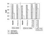
本発明の効果を実施例として説明する。
図2および図3は本発明の効果を説明するための説明図である。図2における縦軸は比出力(kw/(kg/s))を示し、横軸は種々の加温パターンを示している。また、図3における縦軸は効率を示し、横軸は図2と同様に種々の加温パターンを示している。
比出力とは、単位都市ガス流量当りのエネルギー回収機器(膨張タービン、熱源機、ランキンサイクル)のトータル出力を言う。また、効率とは、熱源機(ガスエンジン)へ投入されるガスエネルギー量に対するエネルギー回収機器のトータル出力の比である。
加温パターンとしては、次の6つの場合を示している。
(i) プレヒート(単純加熱:都市ガスを単純に燃焼させて加熱する)
(ii) プレヒート(ガスエンジン排熱加熱)
(iii)アフターヒート(単純加熱)
(iv) アフターヒート(ガスエンジン排熱加熱)
(v) アフターヒート(ガスエンジン+ランキンサイクル)
(vi) プレヒート+アフターヒート(ガスエンジン+ランキンサイクル)The effect of this invention is demonstrated as an Example.
2 and 3 are explanatory diagrams for explaining the effect of the present invention. The vertical axis in FIG. 2 indicates the specific output (kw / (kg / s)), and the horizontal axis indicates various heating patterns. Further, the vertical axis in FIG. 3 indicates the efficiency, and the horizontal axis indicates various heating patterns as in FIG.
Specific output is the total output of energy recovery equipment (expansion turbine, heat source unit, Rankine cycle) per unit city gas flow rate. The efficiency is the ratio of the total output of the energy recovery device to the amount of gas energy input to the heat source machine (gas engine).
As the heating pattern, the following six cases are shown.
(i) Preheat (simple heating: simply burn city gas to heat)
(ii) Preheat (gas engine exhaust heat heating)
(iii) After heat (simple heating)
(iv) After heat (gas engine exhaust heat heating)
(v) After heat (gas engine + Rankine cycle)
(vi) Preheat + Afterheat (Gas engine + Rankine cycle)
試算にあたっては、以下の条件とした。
(1)都市ガス成分:メタン
(2)膨張タービン内部効率:75%
(3)1次側(減圧前)ガス入口温度:10℃、2次側(減圧後)ガス出口温度:5℃
(4)ガスエンジン仕様:効率(=軸出力/投入燃料熱量)=0.4、利用可能排熱割合(=利用可能排熱量/投入燃料熱量)=0.48
(5)ランキンサイクル効率(=軸出力/高温熱源からの入熱量)=0.2
なお、一次側圧力は6MPaと20MPaの2ケース、膨張圧力比(=一次側圧力/二次側圧力)は2とした。The following conditions were used for the trial calculation.
(1) City gas component: Methane (2) Expansion turbine internal efficiency: 75%
(3) Primary side (before decompression) gas inlet temperature: 10 ° C, Secondary side (after decompression) gas outlet temperature: 5 ° C
(4) Gas engine specifications: Efficiency (= shaft output / input fuel heat amount) = 0.4, usable exhaust heat ratio (= available exhaust heat amount / input fuel heat amount) = 0.48
(5) Rankine cycle efficiency (= shaft output / heat input from high-temperature heat source) = 0.2
The primary pressure was 2 cases of 6 MPa and 20 MPa, and the expansion pressure ratio (= primary side pressure / secondary side pressure) was 2.
まず、図2に示されるように、単純加熱の場合より、ガスエンジン排熱にて加熱した方が、比出力が向上する。
また、図2、図3に示されるように、単純加熱およびガスエンジン排熱加熱のケースでは、プレヒートの方がアフターヒートより比出力、効率ともに大きく、好ましい。
さらに、アフターヒート方式において、ガスエンジンとランキンサイクルを組み合わせて、ガスエンジン排熱および膨張タービン出口発生冷熱を、それぞれ、ランキンサイクル高温熱源および低温熱源として利用することにより、比出力、効率ともにさらに向上している。本試算の例では、アフターヒート方式でガスエンジンとランキンサイクルを組み合わせた構成が最も比出力・効率ともに大きく、好ましい。
ただし、アフターヒートのみで対応する場合、膨張タービン出口温度がマイナス数十度以下となる場合があり、都市ガスの性状に悪影響を及ぼす可能性や機器の耐久性に支障をきたす場合がある。
逆に、プレヒートのみで対応する場合、二次側ガス温度を0℃以上に保つためにはプレヒート温度が100℃超となる場合があり、安全面や機器の耐久性に支障をきたす場合がある。
このように、アフターヒートとプレヒートのいずれか一方のみで対応する場合には好ましくない場合が考えられるので、このような場合、プレヒートとアフターヒートを適当な割合で組み合わせるのが好ましい。この意味で、排熱分配供給装置11を設けたことに大きな意義がある。First, as shown in FIG. 2, the specific power is improved by heating with gas engine exhaust heat, as compared with the case of simple heating.
In addition, as shown in FIGS. 2 and 3, in the case of simple heating and gas engine exhaust heat heating, preheating is preferable because both specific output and efficiency are larger than afterheating.
Furthermore, in the after heat method, the specific output and efficiency are further improved by combining the gas engine and the Rankine cycle, and using the exhaust heat from the gas engine and the cooling heat generated at the outlet of the expansion turbine as the high temperature heat source and low temperature heat source, respectively. is doing. In the example of this trial calculation, a configuration in which a gas engine and a Rankine cycle are combined in an after-heat method is most preferable because it has the largest specific output and efficiency.
However, when dealing with only after heat, the temperature at the outlet of the expansion turbine may be minus several tens of degrees or less, which may adversely affect the properties of city gas and may impair the durability of the equipment.
Conversely, when only preheating is used, the preheating temperature may exceed 100 ° C in order to keep the secondary gas temperature above 0 ° C, which may hinder safety and durability of the equipment. .
As described above, when dealing with only one of the afterheat and the preheat, it may be not preferable. In such a case, it is preferable to combine the preheat and the afterheat at an appropriate ratio. In this sense, the provision of the exhaust heat distribution and
本試算のプレヒート+アフターヒート例では、膨張弁出口でのガス温度が5℃となるようにプレヒート量を調整し、膨張タービン出口で低温となったガスをアフターヒータ5で加温して5℃としている。このようにすることによって、プレヒータ、アフターヒータともに温度条件がマイルドになり実用上好ましい場合が多い。
実際には一次圧・二次圧条件などにより、プレヒートとアフターヒートのバランスを適宜選定することになる。In this pre-calculated preheat + afterheat example, the preheat amount is adjusted so that the gas temperature at the expansion valve outlet becomes 5 ° C, and the low temperature gas at the expansion turbine outlet is heated by the
Actually, the balance between preheating and afterheating is appropriately selected depending on the primary pressure and secondary pressure conditions.
なお、上記の例では膨張タービン1を1段設置した場合を示したが、膨張タービン及びアフターヒータをそれぞれ複数設けることにより、比出力及び効率を変化させることができる。例えば、トータルの圧力比が8の場合、つまり減圧設備出口圧を入口圧の1/8に調整したい場合、圧力比2の膨張タービンを3段組み合わせ、各段の間にアフターヒータを設置して各段での発生冷熱を回収するようにすることにより、効率の高いシステムとすることができる。 In addition, although the case where the expansion turbine 1 was installed in one stage was shown in said example, specific output and efficiency can be changed by providing multiple each of an expansion turbine and an after heater. For example, if the total pressure ratio is 8, that is, if you want to adjust the outlet pressure of the decompression equipment to 1/8 of the inlet pressure, combine three stages of expansion turbines with a pressure ratio of 2 and install an after heater between each stage. By recovering the generated cold heat at each stage, a highly efficient system can be obtained.
なお、ランキンサイクル9に代えてアンモニアと水の混合物質を用いたカリーナサイクル、ウエハラサイクルなどを用いてもよい。
さらに、ランキンサイクル9に代えて等容加熱、等温膨張、等容冷却、等温圧縮という各過程によって構成される熱サイクルであるスターリングサイクルを適用することもできる。
また、本実施形態では膨張機として膨張タービン1を用いた例を示したが、タービン以外の方式、例えばスクリュー方式やレシプロ方式、ロータリー方式などの膨張機を用いても、もちろんよい。Instead of the
Furthermore, instead of the
Moreover, although the example which used the expansion turbine 1 as an expander was shown in this embodiment, of course, you may use expanders, such as systems other than a turbine, for example, a screw system, a reciprocating system, a rotary system.
1 膨張タービン
3 前加熱器(プレヒータ)
5 後加熱器(アフターヒータ)
7 原動機
9 ランキンサイクル
11 排熱分配供給装置
13 第1発電機
15 膨張弁
17 第2発電機
19 第3発電機1
5 Post-heater (after heater)
7
Claims (7)
Translated fromJapanesePriority Applications (1)
| Application Number | Priority Date | Filing Date | Title |
|---|---|---|---|
| JP2007268356AJP2009097389A (en) | 2007-10-15 | 2007-10-15 | Decompression equipment with energy recovery function |
Applications Claiming Priority (1)
| Application Number | Priority Date | Filing Date | Title |
|---|---|---|---|
| JP2007268356AJP2009097389A (en) | 2007-10-15 | 2007-10-15 | Decompression equipment with energy recovery function |
Publications (1)
| Publication Number | Publication Date |
|---|---|
| JP2009097389Atrue JP2009097389A (en) | 2009-05-07 |
Family
ID=40700634
Family Applications (1)
| Application Number | Title | Priority Date | Filing Date |
|---|---|---|---|
| JP2007268356APendingJP2009097389A (en) | 2007-10-15 | 2007-10-15 | Decompression equipment with energy recovery function |
Country Status (1)
| Country | Link |
|---|---|
| JP (1) | JP2009097389A (en) |
Cited By (4)
| Publication number | Priority date | Publication date | Assignee | Title |
|---|---|---|---|---|
| JP2010261416A (en)* | 2009-05-11 | 2010-11-18 | Tokyo Gas Co Ltd | Energy storage device and pressure difference power generation system using the same |
| JP2013100743A (en)* | 2011-11-07 | 2013-05-23 | Astencook:Kk | Power generating device utilizing city gas |
| JP2013204583A (en)* | 2012-03-29 | 2013-10-07 | Osaka Gas Co Ltd | Engine and fuel supply method thereof |
| CN104533531A (en)* | 2015-01-06 | 2015-04-22 | 无锡玄同科技有限公司 | System and device for recovering pressure energy of natural gas pipeline as well as rotor expander |
- 2007
- 2007-10-15JPJP2007268356Apatent/JP2009097389A/enactivePending
Cited By (4)
| Publication number | Priority date | Publication date | Assignee | Title |
|---|---|---|---|---|
| JP2010261416A (en)* | 2009-05-11 | 2010-11-18 | Tokyo Gas Co Ltd | Energy storage device and pressure difference power generation system using the same |
| JP2013100743A (en)* | 2011-11-07 | 2013-05-23 | Astencook:Kk | Power generating device utilizing city gas |
| JP2013204583A (en)* | 2012-03-29 | 2013-10-07 | Osaka Gas Co Ltd | Engine and fuel supply method thereof |
| CN104533531A (en)* | 2015-01-06 | 2015-04-22 | 无锡玄同科技有限公司 | System and device for recovering pressure energy of natural gas pipeline as well as rotor expander |
Similar Documents
| Publication | Publication Date | Title |
|---|---|---|
| US7096665B2 (en) | Cascading closed loop cycle power generation | |
| CN102792021B (en) | Utilize the apparatus and method generated electricity by the steam using solar energy to produce and/or hot water | |
| JP6808166B2 (en) | Generation of process steam by high temperature heat pump | |
| EP2446122B1 (en) | System and method for managing thermal issues in one or more industrial processes | |
| US8881528B2 (en) | System for the generation of mechanical and/or electrical energy | |
| JP6245404B1 (en) | Combustion equipment and power generation equipment | |
| JP2014109279A (en) | Gas turbine engine with integrated bottoming cycle system | |
| US20210239041A1 (en) | Apparatus, process and thermodynamic cycle for power generation with heat recovery | |
| KR20050056941A (en) | Cascading closed loop cycle power generation | |
| US7950214B2 (en) | Method of and apparatus for pressurizing gas flowing in a pipeline | |
| US11300010B2 (en) | Cooling equipment, combined cycle plant comprising same, and cooling method | |
| US10309259B2 (en) | CO2 power generation system | |
| US9708973B2 (en) | Integrated reformer and waste heat recovery system for power generation | |
| US20140360191A1 (en) | Energy storage apparatus for the preheating of feed water | |
| KR20180120234A (en) | Combination Cycle Power Plant | |
| KR101752230B1 (en) | Generation system using supercritical carbon dioxide and method of driving the same by heat sink temperature | |
| JP2009097389A (en) | Decompression equipment with energy recovery function | |
| JP4666641B2 (en) | Energy supply system, energy supply method, and energy supply system remodeling method | |
| JP2009180101A (en) | Decompression equipment with energy recovery function | |
| MXPA06010263A (en) | Method of power generation from pressure control stations of a natural gas distribution sytem. | |
| KR101936327B1 (en) | Combined Heat and power system using supercritical carbon dioxide power cycle | |
| JP3697476B2 (en) | Combined power generation system using gas pressure energy | |
| JP2025526337A (en) | Electrolytic Energy Recovery | |
| RU2656769C1 (en) | Thermal power plant gas turboexpander power unit operation method | |
| CN111512096A (en) | Cogeneration system for boiler |