JP2009094026A - Lighting unit - Google Patents
Lighting unitDownload PDFInfo
- Publication number
- JP2009094026A JP2009094026AJP2007266152AJP2007266152AJP2009094026AJP 2009094026 AJP2009094026 AJP 2009094026AJP 2007266152 AJP2007266152 AJP 2007266152AJP 2007266152 AJP2007266152 AJP 2007266152AJP 2009094026 AJP2009094026 AJP 2009094026A
- Authority
- JP
- Japan
- Prior art keywords
- light
- substrate
- semiconductor light
- reflector
- light source
- Prior art date
- Legal status (The legal status is an assumption and is not a legal conclusion. Google has not performed a legal analysis and makes no representation as to the accuracy of the status listed.)
- Granted
Links
Images


Classifications
- F—MECHANICAL ENGINEERING; LIGHTING; HEATING; WEAPONS; BLASTING
- F21—LIGHTING
- F21V—FUNCTIONAL FEATURES OR DETAILS OF LIGHTING DEVICES OR SYSTEMS THEREOF; STRUCTURAL COMBINATIONS OF LIGHTING DEVICES WITH OTHER ARTICLES, NOT OTHERWISE PROVIDED FOR
- F21V7/00—Reflectors for light sources
- F21V7/04—Optical design
- F21V7/09—Optical design with a combination of different curvatures
- F—MECHANICAL ENGINEERING; LIGHTING; HEATING; WEAPONS; BLASTING
- F21—LIGHTING
- F21V—FUNCTIONAL FEATURES OR DETAILS OF LIGHTING DEVICES OR SYSTEMS THEREOF; STRUCTURAL COMBINATIONS OF LIGHTING DEVICES WITH OTHER ARTICLES, NOT OTHERWISE PROVIDED FOR
- F21V7/00—Reflectors for light sources
- F21V7/0008—Reflectors for light sources providing for indirect lighting
- F—MECHANICAL ENGINEERING; LIGHTING; HEATING; WEAPONS; BLASTING
- F21—LIGHTING
- F21V—FUNCTIONAL FEATURES OR DETAILS OF LIGHTING DEVICES OR SYSTEMS THEREOF; STRUCTURAL COMBINATIONS OF LIGHTING DEVICES WITH OTHER ARTICLES, NOT OTHERWISE PROVIDED FOR
- F21V7/00—Reflectors for light sources
- F21V7/005—Reflectors for light sources with an elongated shape to cooperate with linear light sources
- F—MECHANICAL ENGINEERING; LIGHTING; HEATING; WEAPONS; BLASTING
- F21—LIGHTING
- F21V—FUNCTIONAL FEATURES OR DETAILS OF LIGHTING DEVICES OR SYSTEMS THEREOF; STRUCTURAL COMBINATIONS OF LIGHTING DEVICES WITH OTHER ARTICLES, NOT OTHERWISE PROVIDED FOR
- F21V3/00—Globes; Bowls; Cover glasses
- F21V3/04—Globes; Bowls; Cover glasses characterised by materials, surface treatments or coatings
- F—MECHANICAL ENGINEERING; LIGHTING; HEATING; WEAPONS; BLASTING
- F21—LIGHTING
- F21W—INDEXING SCHEME ASSOCIATED WITH SUBCLASSES F21K, F21L, F21S and F21V, RELATING TO USES OR APPLICATIONS OF LIGHTING DEVICES OR SYSTEMS
- F21W2131/00—Use or application of lighting devices or systems not provided for in codes F21W2102/00-F21W2121/00
- F21W2131/30—Lighting for domestic or personal use
- F21W2131/305—Lighting for domestic or personal use for refrigerators
- F—MECHANICAL ENGINEERING; LIGHTING; HEATING; WEAPONS; BLASTING
- F21—LIGHTING
- F21W—INDEXING SCHEME ASSOCIATED WITH SUBCLASSES F21K, F21L, F21S and F21V, RELATING TO USES OR APPLICATIONS OF LIGHTING DEVICES OR SYSTEMS
- F21W2131/00—Use or application of lighting devices or systems not provided for in codes F21W2102/00-F21W2121/00
- F21W2131/40—Lighting for industrial, commercial, recreational or military use
- F21W2131/405—Lighting for industrial, commercial, recreational or military use for shop-windows or displays
- F—MECHANICAL ENGINEERING; LIGHTING; HEATING; WEAPONS; BLASTING
- F21—LIGHTING
- F21Y—INDEXING SCHEME ASSOCIATED WITH SUBCLASSES F21K, F21L, F21S and F21V, RELATING TO THE FORM OR THE KIND OF THE LIGHT SOURCES OR OF THE COLOUR OF THE LIGHT EMITTED
- F21Y2103/00—Elongate light sources, e.g. fluorescent tubes
- F21Y2103/10—Elongate light sources, e.g. fluorescent tubes comprising a linear array of point-like light-generating elements
- F—MECHANICAL ENGINEERING; LIGHTING; HEATING; WEAPONS; BLASTING
- F21—LIGHTING
- F21Y—INDEXING SCHEME ASSOCIATED WITH SUBCLASSES F21K, F21L, F21S and F21V, RELATING TO THE FORM OR THE KIND OF THE LIGHT SOURCES OR OF THE COLOUR OF THE LIGHT EMITTED
- F21Y2115/00—Light-generating elements of semiconductor light sources
- F21Y2115/10—Light-emitting diodes [LED]
- H—ELECTRICITY
- H01—ELECTRIC ELEMENTS
- H01L—SEMICONDUCTOR DEVICES NOT COVERED BY CLASS H10
- H01L25/00—Assemblies consisting of a plurality of semiconductor or other solid state devices
- H01L25/03—Assemblies consisting of a plurality of semiconductor or other solid state devices all the devices being of a type provided for in a single subclass of subclasses H10B, H10D, H10F, H10H, H10K or H10N, e.g. assemblies of rectifier diodes
- H01L25/04—Assemblies consisting of a plurality of semiconductor or other solid state devices all the devices being of a type provided for in a single subclass of subclasses H10B, H10D, H10F, H10H, H10K or H10N, e.g. assemblies of rectifier diodes the devices not having separate containers
- H01L25/075—Assemblies consisting of a plurality of semiconductor or other solid state devices all the devices being of a type provided for in a single subclass of subclasses H10B, H10D, H10F, H10H, H10K or H10N, e.g. assemblies of rectifier diodes the devices not having separate containers the devices being of a type provided for in group H10H20/00
- H01L25/0753—Assemblies consisting of a plurality of semiconductor or other solid state devices all the devices being of a type provided for in a single subclass of subclasses H10B, H10D, H10F, H10H, H10K or H10N, e.g. assemblies of rectifier diodes the devices not having separate containers the devices being of a type provided for in group H10H20/00 the devices being arranged next to each other
- H—ELECTRICITY
- H01—ELECTRIC ELEMENTS
- H01L—SEMICONDUCTOR DEVICES NOT COVERED BY CLASS H10
- H01L2924/00—Indexing scheme for arrangements or methods for connecting or disconnecting semiconductor or solid-state bodies as covered by H01L24/00
- H01L2924/0001—Technical content checked by a classifier
- H01L2924/0002—Not covered by any one of groups H01L24/00, H01L24/00 and H01L2224/00
- H—ELECTRICITY
- H10—SEMICONDUCTOR DEVICES; ELECTRIC SOLID-STATE DEVICES NOT OTHERWISE PROVIDED FOR
- H10H—INORGANIC LIGHT-EMITTING SEMICONDUCTOR DEVICES HAVING POTENTIAL BARRIERS
- H10H20/00—Individual inorganic light-emitting semiconductor devices having potential barriers, e.g. light-emitting diodes [LED]
- H10H20/80—Constructional details
- H10H20/85—Packages
- H10H20/855—Optical field-shaping means, e.g. lenses
- H10H20/856—Reflecting means
Landscapes
- Engineering & Computer Science (AREA)
- General Engineering & Computer Science (AREA)
- Non-Portable Lighting Devices Or Systems Thereof (AREA)
- Arrangement Of Elements, Cooling, Sealing, Or The Like Of Lighting Devices (AREA)
- Planar Illumination Modules (AREA)
- Fastening Of Light Sources Or Lamp Holders (AREA)
- Led Device Packages (AREA)
- Light Sources And Details Of Projection-Printing Devices (AREA)
Abstract
Translated fromJapaneseDescription
Translated fromJapanese本発明は、半導体光源を用いた照明ユニット関し、特にライン状に複数の半導体光源が搭載された照明ユニットに関するものである。 The present invention relates to an illumination unit using a semiconductor light source, and more particularly to an illumination unit in which a plurality of semiconductor light sources are mounted in a line shape.
近年、蛍光灯の変わりとなる照明用ユニットとして、発光ダイオードなどの半導体光源を用いたライン状の照明ユニットが提案されている。例えば、光の光束を高めることを目的として、基板の長手方向に沿って実装された複数個のLEDチップと、このLEDチップ全体を一体的に覆うように形成された略半円柱状、または、かまぼこ形状の透明樹脂部と、を備えた照明ユニットが開示されている。
しかしながら、上記照明ユニットは、照射範囲が狭いことから、広範囲に光を均一に照射する照明用途には不適切であった。However, since the illumination unit has a narrow irradiation range, it is unsuitable for illumination applications that uniformly irradiate light over a wide range.
そこで本発明は、広範囲に光を均一に照射することが可能な照明ユニットを提供する。Therefore, the present invention provides an illumination unit capable of uniformly irradiating light over a wide range.
本発明の照明ユニットは、長尺な基板と、前記基板の長手方向に列設された複数の半導体光源と、前記複数の半導体光源からの光を前記基板の短手方向の一方の方向へ取り出すことが可能な光反射体と、を備え、前記光反射体は、複数の小片が合成されたマルチリフレクタを有していることを特徴とする。The illumination unit of the present invention takes out a long substrate, a plurality of semiconductor light sources arranged in a longitudinal direction of the substrate, and light from the plurality of semiconductor light sources in one direction in a short direction of the substrate. And a light reflector, the light reflector having a multi-reflector in which a plurality of small pieces are combined.
前記複数の小片は、前記半導体光源からの光をそれぞれ異なる光軸を有する反射光として取り出すことが可能となるように配置角度が調整されていることが好ましい。また、記複数の小片は、前記半導体光源から離れて配置される小片ほど大きな面積と長い焦点距離を有していることが好ましい。It is preferable that the arrangement angle of the plurality of small pieces is adjusted so that light from the semiconductor light source can be extracted as reflected light having different optical axes. In addition, it is preferable that the plurality of small pieces have a larger area and a longer focal length as the smaller pieces are arranged away from the semiconductor light source.
前記光反射体は、前記複数の半導体光源の間に突出したサイドリフレクタを有していることが好ましい。The light reflector preferably includes a side reflector protruding between the plurality of semiconductor light sources.
さらに、前記基板の他方の長辺側に、光拡散効果を有するカバーを備えていることが好ましい。Furthermore, it is preferable that a cover having a light diffusion effect is provided on the other long side of the substrate.
本発明の照明ユニットは、複数の小片が合成されたマルチリフレクタを有する長尺照明ユニットであることから、長手方向には蛍光灯と同等の光学特性を持たせつつ、照明ユニットから離れた位置においても高い照度を得ることができる。 Since the illumination unit of the present invention is a long illumination unit having a multi-reflector in which a plurality of small pieces are combined, it has optical characteristics equivalent to those of a fluorescent lamp in the longitudinal direction, but at a position away from the illumination unit. High illuminance can be obtained.
本発明の発光装置の実施の形態を以下に詳細に説明する。
実施の形態1
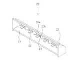
図1(a)の上面側からみた模式的斜視図、図1(b)の基板短手方向における模式的断面図に示すように、この実施の形態の照明ユニット10は、主として、長尺な基板11、前記基板上の長手方向に列設された複数の半導体光源12、および前記基板上の一方の長辺側に沿って配置された光反射体13により構成されている。Embodiments of the light emitting device of the present invention will be described in detail below.
Embodiment 1
As shown in the schematic perspective view seen from the upper surface side of FIG. 1A and the schematic cross-sectional view in the short-side direction of the substrate of FIG. 1B, the
基板11は、長手方向に延長した形状に形成されており、基板11の上面側において、複数の半導体光源12が長手方向に列設されている。基板11は、上面及び上面と対向する底面に、半導体光源12を発光させるための配線、配線パターンを有し、異なる素子の搭載がされている等、当該分野で公知の手段が施された基板である。基板の材料は、熱伝導性の高い材料を用いることが好ましく、ガラスエポキシ基板やアルミ基板が好適に用いられる。また、熱伝導性が好ましくない基板を用いる場合、基板11の底面側に熱伝導性の良い金属基板を接合することが好ましい。さらに、基板11と金属基板との間に、熱伝導性シート(図示していない)を備えていることが好ましい。熱伝導性シートは、例えば、1W/(m・K)程度以上の熱伝導率を有し、かつ、絶縁性のものが好ましい。これにより、基板11と金属基板との導通を防止し、半導体光源12間にてショートすることなく半導体光源12から発生する熱を効率的に放熱することができる。具体的には、シリコーンゴム等により形成することができる。その厚み、形状及び大きさ等は、得ようとする照明ユニットの大きさ、形状等を考慮して適宜調整することができるが、基板12と略同じ形状、同じ大きさであることが好ましい。The substrate 11 is formed in a shape extending in the longitudinal direction, and a plurality of
半導体光源12は、光を発光することが可能な半導体であれば特に限定されるものではなく、当該分野で使用されているもののいずれをも使用することができる。また、半導体光源12は、半導体素子チップ自体を用いてもよく、パッケージや被覆部材等により覆われた半導体発光装置を用いてもよい。後者の場合、各構成部材に波長変換部材(例えば、蛍光体等)、拡散剤等が含有されていてもよいし、複数の半導体素子チップが搭載されていてもよい。特に、RBGに対応したフルカラーの半導体発光装置を用いることにより、単色の発光素子を用いる場合よりも、混色性を向上させることができる。 The
また、半導体光源12は、前記基板の上方側から観測した際の配光が略ランバート分布配光であることが好ましい。これにより、輝度ムラの少なく、高効率でグレアの少ない照明ユニットとすることができる。さらに半導体光源12は、基板11上に等間隔で配置されていることが好ましい。これにより、均一な光の分布を実現することができるとともに、半導体光源12から発生する熱の分布を均等にすることができる。Moreover, it is preferable that the light distribution when the
本実施の形態の光反射体13は、側面と背面を有し、該背面部分は、半導体光源12が搭載された基板11の一方の長辺側に沿って配置されており、半導体光源12の上方まで延在している。光反射体13の側面は、基板11の側面と固定されている。光反射体13の背面部分は、複数の小片が合成されたマルチリフレクタ13aを有している。 The
本実施の形態の光反射体13は、光反射体13の全面において基板11の長辺とほぼ同じ長さの長尺形状の小片が複数上下方向に合成されてなるマルチリフレクタ13aが構成されているが、各小片の形状および面積は、照射したい領域の範囲、その領域までの距離、およびその領域に対する光入射角度にあわせて任意に調整することができる。The
前記複数の小片は、前記半導体光源からの光をそれぞれ異なる光軸を有する反射光として取り出すことが可能となるように配置角度が調整されていることが好ましい。これにより、広い範囲において均一な照度を有することが可能な照明ユニットを得ることができる。It is preferable that the arrangement angle of the plurality of small pieces is adjusted so that light from the semiconductor light source can be extracted as reflected light having different optical axes. Thereby, the illumination unit which can have uniform illumination intensity in a wide range can be obtained.
また、複数の小片は、前記半導体光源から離れて配置される小片ほど大きな面積と長い焦点距離を有していることが好ましい。このようにマルチリフレクタを構成することにより、半導体光源12から離れて配置されている小片側にて遠方を集光照射し、半導体光源12の近くに配置されている小片側にて近距離を集光照射することが可能となり、より広い範囲において均一な照度を有することが可能な照明ユニットを得ることができる。例えば、このような形態の照明ユニットを、多段型オープンショーケースの最上部手前に取り付け、庫内側を照射すると、上方の棚だけでなく下方の棚まで均一に照射することができる。これにより、多段型オープンショーケースにおいて、庫内の各棚下部分に照明を取り付ける必要がなくなり、大幅にコストを下げることができる。また、半導体光源を用いることで、ランニングコスト・メンテナンスコストも低減することができる。Further, it is preferable that the plurality of small pieces have a larger area and a longer focal length as the smaller pieces are arranged away from the semiconductor light source. By constructing the multi-reflector in this way, the far side is condensed and irradiated on the small piece side arranged away from the
小片は、輝度・色ムラが照射ムラに影響する半導体光源を使用する場合、マルチリフレクタの光反射面に拡散効果のある加工が施されていることが望ましい。When using a semiconductor light source whose luminance and color unevenness affects the irradiation unevenness, it is desirable that the small piece is processed with a diffusion effect on the light reflecting surface of the multi-reflector.
また、小片の光反射面を半導体光源12の光を集光する球面または非球面(放物面、楕円面等)とし、これらの配置角度を調整して得られたマルチリフレクタ13aの形状が、半導体光源12を焦点とするシリンドリカルミラー形状であることが好ましい。これにより半導体光源12から出射された光が、長尺方向においては広範囲に照度・色むらがなく、短尺方向においては所望範囲に均一な照度分布となるよう効率よく集光される照明ユニットが得られる。また、マルチリフレクタ13を、半導体光源12を焦点とするデフォーカスミラー形状としてもよく、これにより、半導体光源12の輝度ムラや色ムラを改善することができる。Further, the light reflecting surface of the small piece is a spherical surface or an aspherical surface (a paraboloidal surface, an elliptical surface, etc.) for condensing the light of the
光反射体13は、ABS、ポリカーボネート、アクリル等の樹脂成型品に光反射性の高い金属膜を蒸着、メッキしたもの、またはAl等金属プレス品に光反射性の高い金属膜を蒸着、メッキしたもの、もしくは高反射膜形成済みAl板材等をプレス加工したものなどにより、形成することができる。また、輝度ムラや色ムラが照射ムラに影響する半導体光源12を用いた場合は、光反射面に拡散効果のある加工が施されていることが好ましい。 The
実施の形態2
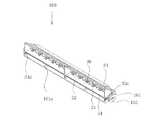
この実施の形態2の照明ユニット20は、図2に示したように、マルチリフレクタ23aは、複数の半導体光源22の間にて分離し、その分離部分にサイドリフレクタ23bを有している以外、実質的に実施の形態1と同様の構成である。Embodiment 2
In the
本実施の形態は、複数のマルチリフレクタ23aと複数の半導体光源22とを有し、それぞれが対を成して配置されている。これにより、各半導体光源22からの光を各マルチリフレクタ23aにより効率よく外部へ取り出すことができ、光の利用効率を高めることができる。また、本実施の形態の光反射体は、各マルチリフレクタ23aの間から各半導体光源22の間に突出したサイドリフレクタ23bを有している。このように、複数の半導体光源の間に突出したサイドリフレクタを有する光反射体を用いることで、基板21の長手方向への非利用光を基板21の短手方向である光取り出し方向側へ効率的に取り出すことができる。 The present embodiment has a plurality of multi-reflectors 23 a and a plurality of
実施の形態3
実施の形態3の照明装置100は、金属プレート34と、半導体光源32が搭載された基板31と、光反射体33と、を有する2組の照明ユニット30を、基板31の長手方向に並べ、1つの筺体101で保持したものである。Embodiment 3
The
金属プレート34は、例えばアルミニウムや銅、鉄、ステンレスなどの熱伝導率の高い金属材料により構成されている。また、金属プレートの形状は板状のみならず、フィンのついたヒートシンク形状や、筐体の構造的機構の一部となる形状が付加されていてもよい。The
本実施の形態3において、半導体光源32およびそれが搭載された基板31は、実施の形態1および2と同様のものを用いることができる。光反射体は、背面の外側に長手方向に沿って配置された長尺リブ部33cを有し、側面の下方に引掛部33dを有している以外は実施の形態2で用いられた光反射体とほぼ同様の構成を有する光反射体33を用いている。光反射体33の引掛部33dには、基板31と合体された金属プレート34が保持されている。このように固定された照明ユニット30は、光反射体33のリブ部33cが筺体101の背面側の勘合開口部に嵌め込まれ、光反射体33の端部と筺体101の端部とがホルダー102にて固定されている。In the third embodiment, the
筺体101は、底面、側面および背面を有し、照明ユニット30を保持している。筺体101の底面の内側には、金属プレート34を短手方向に保持する長尺リブ部101aを複数有しており、これにより、金属プレート34の放熱性を妨げることなく照明ユニット30を安定して保持することができる。筺体101の側面には、金属プレートの端部に設けられた凸部と対応する箇所に同様の形状の凸部を有しており、筺体101の凸部と、照明ユニット30と合体された金属プレートの凸部とが、ホルダーにより固定されている。また、筺体101の背面には、光反射体33のリブ部33cが勘合する勘合開口部と、光反射体33の背面上方を保持する鍔部とを有している。このような構成にすることにより、螺子等の固定部材を別途用いることなく、簡便かつ容易に照明ユニットを筺体に取り付けることができる。The
ホルダー101は、光反射体33の端部から突出した凸部と筺体101の端部から突出した凸部とを保持することが可能であれば特に限定されず、固定用ホルダーとして従来から通常用いられているものであれば特に限定されるものではない。The
実施の形態4
本実施の形態4の照明装置200は、図4に示したように、照明ユニットの光取り出し側に、光拡散効果を有するカバー203を備えている以外は、実質的に実施の形態3と同様の構成である。このように、光反射体が配置された基板長辺と対向する他方の長辺側に、光拡散効果を有するカバー203を備えることにより、輝度・色ムラが照射ムラに影響する半導体光源を使用した際においても、これらの照射ムラを抑制することが可能な照明ユニットおよび照明装置を得ることができる。Embodiment 4
As shown in FIG. 4, the
カバー203は、半導体光源からの光を透過することが可能な材料にて構成されていれば特に限定されず、当該分野で公知の材料によって形成することができるが、例えば、軽量で、強度の強いプラスチック、特に加工性および耐熱性を考慮すると、ポリカーボネートやアクリルなどの樹脂材料にて構成されていることが好ましい。ここで、本明細書における光透過性とは、搭載する半導体光源13からの光を100%透過することが好ましいが、混色、色むら等を考慮して、半透明及び不透明(例えば、光透過性が50%程度以上、乳白色のもの等)のものも含むものとする。 The
ここで、光拡散効果とは、半導体光源からの光を拡散し得る部分を意味し、カバー自体に光拡散効果が加工されていてもよいし、カバー203に光拡散効果を有する他の部材を組み合わせて構成されていてもよい。例えば、カバー203の正面側及び/又は背面側(内側)に拡散シート(例えば、半透明及び乳白色樹脂製の厚さの薄いシート)を貼り付けてもよいし、カバーの正面側及び/又は背面にサンドブラスト、研磨等の粗面処理を施してもよい。さらに、カバー203を形成する材料自体に拡散剤(例えば、酸化シリコン等のフィラー等)を混入してもよい。これにより、各半導体光源からの光を均一なひとつの面光源とすることができる。Here, the light diffusion effect means a portion that can diffuse the light from the semiconductor light source, and the cover itself may be processed with the light diffusion effect, or another member having the light diffusion effect may be provided on the
カバー203は、光観測面の背面側周縁部に、照明ユニット40に着脱可能に嵌め込むことが可能な取付部203aを備えている。取付部203aは、半導体光源13からの発光に対して悪影響を与えない部位に配置されることが好ましい。The
取付部203aは、カバー203と同じ材料によって、カバー203と一体的に形成されていることが好ましい。これにより、照明装置の部品数を低減させ、安価でかつ組立てを容易とすることができる。The
本実施の形態の照明ユニット40は、カバー203にて封止されていることから、冷蔵庫等の霜が着く可能性がある所に使用することも可能である。Since the
本発明の照明ユニットは、多段オープンショーケース用照明をはじめ、標識灯、建築照明など、種々の照明用途として利用することができる。 The lighting unit of the present invention can be used for various lighting applications such as multi-stage open showcase lighting, marker lamps, and architectural lighting.
10、20、30、40 照明ユニット
11、21、31 基板
12、22、33 半導体光源
13、23、33 光反射体
13a、23a マルチリフレクタ
15 光線
23b サイドリフレクタ
33c リブ部
33d 引掛部
34 金属プレート
100、200 照明装置
101、201 筺体
101a、201a リブ部
102、202 ホルダー
203 カバー
203a 取付部10, 20, 30, 40
Claims (5)
Translated fromJapanese前記光反射体は、複数の小片が合成されたマルチリフレクタを有していることを特徴とする照明ユニット。A long substrate, a plurality of semiconductor light sources arranged in a longitudinal direction on the substrate, and a light reflector disposed along one long side of the substrate,
The light reflector includes a multi-reflector in which a plurality of small pieces are combined.
Priority Applications (6)
| Application Number | Priority Date | Filing Date | Title |
|---|---|---|---|
| JP2007266152AJP5186875B2 (en) | 2007-10-12 | 2007-10-12 | Lighting unit |
| PCT/JP2008/067909WO2009048011A1 (en) | 2007-10-12 | 2008-10-02 | Illuminating unit |
| CN200880110963XACN101821549B (en) | 2007-10-12 | 2008-10-02 | lighting unit |
| US12/682,014US8721131B2 (en) | 2007-10-12 | 2008-10-02 | Lighting unit |
| EP08837004.4AEP2211088B1 (en) | 2007-10-12 | 2008-10-02 | Illuminating unit |
| TW097138652ATWI442005B (en) | 2007-10-12 | 2008-10-08 | Lighting unit |
Applications Claiming Priority (1)
| Application Number | Priority Date | Filing Date | Title |
|---|---|---|---|
| JP2007266152AJP5186875B2 (en) | 2007-10-12 | 2007-10-12 | Lighting unit |
Publications (2)
| Publication Number | Publication Date |
|---|---|
| JP2009094026Atrue JP2009094026A (en) | 2009-04-30 |
| JP5186875B2 JP5186875B2 (en) | 2013-04-24 |
Family
ID=40549156
Family Applications (1)
| Application Number | Title | Priority Date | Filing Date |
|---|---|---|---|
| JP2007266152AActiveJP5186875B2 (en) | 2007-10-12 | 2007-10-12 | Lighting unit |
Country Status (6)
| Country | Link |
|---|---|
| US (1) | US8721131B2 (en) |
| EP (1) | EP2211088B1 (en) |
| JP (1) | JP5186875B2 (en) |
| CN (1) | CN101821549B (en) |
| TW (1) | TWI442005B (en) |
| WO (1) | WO2009048011A1 (en) |
Cited By (6)
| Publication number | Priority date | Publication date | Assignee | Title |
|---|---|---|---|---|
| JP2011142019A (en)* | 2010-01-07 | 2011-07-21 | Panasonic Electric Works Co Ltd | Luminaire |
| JP2012033283A (en)* | 2010-07-28 | 2012-02-16 | Nichia Corp | Lighting device |
| JP2012074317A (en)* | 2010-09-29 | 2012-04-12 | Panasonic Corp | Lighting system, lamp, and showcase |
| JP2016119204A (en)* | 2014-12-19 | 2016-06-30 | パナソニックIpマネジメント株式会社 | Projector |
| JP2017519344A (en)* | 2014-06-25 | 2017-07-13 | ケーエムダブリュ・インコーポレーテッド | Indirect lighting device using LED |
| JP2019207830A (en)* | 2018-05-30 | 2019-12-05 | コイズミ照明株式会社 | Luminaire |
Families Citing this family (25)
| Publication number | Priority date | Publication date | Assignee | Title |
|---|---|---|---|---|
| JP5534317B2 (en)* | 2010-03-09 | 2014-06-25 | アイティーエル株式会社 | Wall lighting device using LED |
| CN103370571A (en)* | 2011-01-19 | 2013-10-23 | 皇家飞利浦电子股份有限公司 | A lighting device and a luminaire comprising the lighting device |
| RU2013138463A (en)* | 2011-01-19 | 2015-02-27 | Конинклейке Филипс Электроникс Н.В. | LIGHTING DEVICE AND LAMP CONTAINING A LIGHTING DEVICE |
| JP5716156B2 (en)* | 2011-03-31 | 2015-05-13 | 株式会社オプトデザイン | Linear light source device using point light source and illumination device for optical reader using the same |
| US8672512B2 (en)* | 2011-09-23 | 2014-03-18 | Hong Kong Applied Science and Technology Research Institute Company Limited | Omni reflective optics for wide angle emission LED light bulb |
| US20130100667A1 (en)* | 2011-10-20 | 2013-04-25 | Mathieu Riendeau | Light beacon |
| CN102522487B (en)* | 2011-12-05 | 2014-10-15 | 深圳市华星光电技术有限公司 | Liquid-crystal display device and LED (Light-Emitting Diode) packaging structure thereof |
| US8814378B2 (en) | 2011-12-05 | 2014-08-26 | Shenzhen China Star Optoelectronics Technology Co., Ltd. | LCD device and LED package structure thereof |
| US20160274318A1 (en) | 2012-03-05 | 2016-09-22 | Nanoprecision Products, Inc. | Optical bench subassembly having integrated photonic device |
| CN104364689B (en)* | 2012-03-05 | 2016-12-07 | 纳米精密产品股份有限公司 | Coupling device with structured reflective surface for coupling fiber input/output |
| RU2647212C1 (en) | 2012-04-11 | 2018-03-14 | Нанопресижен Продактс, Инк. | Sealed assembly for optical fiber alignment |
| MX344101B (en)* | 2012-07-10 | 2016-12-05 | Emergency Tech Inc | Emergency vehicle light fixture. |
| DE102012216633A1 (en)* | 2012-09-18 | 2014-03-20 | as2 alternative solutions GmbH | Lighting concept for refrigerated cabinets |
| CN103851364A (en)* | 2012-11-30 | 2014-06-11 | 海洋王(东莞)照明科技有限公司 | lamps |
| CN103234130A (en)* | 2013-05-08 | 2013-08-07 | 美格顿(江门)电子照明有限公司 | Lamp capable of weakening glare |
| CN104344231A (en)* | 2013-07-24 | 2015-02-11 | 云光科技股份有限公司 | Lighting device |
| DE102015101252B4 (en) | 2015-01-28 | 2023-10-19 | Chromasens Gmbh | Illumination device, optical analysis system and method for scanning a surface |
| US20170023208A1 (en)* | 2015-07-22 | 2017-01-26 | JST Performance, LLC | Method and apparatus for indirect lighting |
| CN105065988A (en)* | 2015-08-10 | 2015-11-18 | 苏州速腾电子科技有限公司 | Diffuse reflection illuminating device |
| CN105066029A (en)* | 2015-08-10 | 2015-11-18 | 苏州速腾电子科技有限公司 | Highly-reflecting film for lamp and lamp |
| CN106764547A (en)* | 2016-11-18 | 2017-05-31 | 中国计量大学 | A kind of LED light supplement lamp for both culturing microalgae |
| KR20180101963A (en)* | 2017-03-06 | 2018-09-14 | 주식회사 루멘스 | Led module |
| CN107091420A (en)* | 2017-05-18 | 2017-08-25 | 赛尔富电子有限公司 | A kind of light distributing system of LED bar graph light fixture |
| TWI641895B (en)* | 2017-10-24 | 2018-11-21 | 友達光電股份有限公司 | Backlight module and display device |
| US11644171B2 (en)* | 2020-01-27 | 2023-05-09 | Ford Global Technologies, Llc | Vehicle perimeter lighting assembly and lighting method |
Citations (8)
| Publication number | Priority date | Publication date | Assignee | Title |
|---|---|---|---|---|
| JPS54161768A (en)* | 1978-06-12 | 1979-12-21 | Ichikoh Ind Ltd | Lamp for automobile |
| JPH01251502A (en)* | 1987-11-17 | 1989-10-06 | Mitsubishi Cable Ind Ltd | Light emitting diode luminaire |
| JPH0725508U (en)* | 1993-10-08 | 1995-05-12 | 株式会社小糸製作所 | Vehicle lighting |
| JPH08510591A (en)* | 1994-03-10 | 1996-11-05 | フィリップス エレクトロニクス ネムローゼ フェンノートシャップ | Reflective bulb |
| JPH10188613A (en)* | 1996-12-27 | 1998-07-21 | Koito Mfg Co Ltd | Vehicle marker lamp |
| JPH11161198A (en)* | 1997-11-28 | 1999-06-18 | Nec Eng Ltd | Light emitting diode reflection plate |
| JP2006173604A (en)* | 2004-12-10 | 2006-06-29 | Agilent Technol Inc | Light-emitting diode display with compartments |
| JP2006332665A (en)* | 2005-05-23 | 2006-12-07 | Avago Technologies General Ip (Singapore) Private Ltd | Light source suitable for lcd backlight display |
Family Cites Families (18)
| Publication number | Priority date | Publication date | Assignee | Title |
|---|---|---|---|---|
| US4218727A (en)* | 1978-07-03 | 1980-08-19 | Sylvan R. Shemitz And Associates, Inc. | Luminaire |
| US4349866A (en)* | 1980-05-27 | 1982-09-14 | General Signal Corporation | Light reflection system with asymmetric reflector assembly |
| JP3625498B2 (en) | 1994-09-21 | 2005-03-02 | 三洋電機株式会社 | Display device |
| US6504301B1 (en)* | 1999-09-03 | 2003-01-07 | Lumileds Lighting, U.S., Llc | Non-incandescent lightbulb package using light emitting diodes |
| EP1264298B1 (en)* | 2000-03-06 | 2007-01-03 | Teledyne Lighting and Display Products, Inc. | Led light source with field-of-view-controlling optics |
| JP2002299697A (en) | 2001-03-29 | 2002-10-11 | Mitsubishi Electric Lighting Corp | Led light-source device and illuminator |
| JP3753011B2 (en)* | 2001-04-11 | 2006-03-08 | 豊田合成株式会社 | Reflective light emitting diode |
| US6641284B2 (en)* | 2002-02-21 | 2003-11-04 | Whelen Engineering Company, Inc. | LED light assembly |
| EP2327925B1 (en)* | 2002-10-18 | 2012-05-23 | Ichikoh Industries, Ltd. | Vehicle lamp with light emitting diodes |
| TW594264B (en)* | 2003-07-09 | 2004-06-21 | Chunghwa Picture Tubes Ltd | A light-projecting device for a backlight module in a flat panel display device |
| US8197110B2 (en)* | 2003-10-10 | 2012-06-12 | Federal Signal Corporation | Light assembly incorporating reflective features |
| US7008079B2 (en)* | 2003-11-21 | 2006-03-07 | Whelen Engineering Company, Inc. | Composite reflecting surface for linear LED array |
| JP2006108333A (en)* | 2004-10-04 | 2006-04-20 | Toyoda Gosei Co Ltd | lamp |
| US7160004B2 (en)* | 2005-03-03 | 2007-01-09 | Dialight Corporation | LED illumination device with a semicircle-like illumination pattern |
| JP2007167376A (en) | 2005-12-22 | 2007-07-05 | Sanyo Electric Co Ltd | Showcase |
| JP2007175130A (en) | 2005-12-27 | 2007-07-12 | Sanyo Electric Co Ltd | Open showcase |
| JP4902223B2 (en)* | 2006-02-22 | 2012-03-21 | 三洋電機株式会社 | Showcase |
| DE102006013856A1 (en)* | 2006-03-23 | 2007-10-04 | Frank Zeller | Soft and focused light generating device has facets selected such that all light cone radiated from facets in specified direction are radiated parallel to each other |
- 2007
- 2007-10-12JPJP2007266152Apatent/JP5186875B2/enactiveActive
- 2008
- 2008-10-02EPEP08837004.4Apatent/EP2211088B1/enactiveActive
- 2008-10-02USUS12/682,014patent/US8721131B2/enactiveActive
- 2008-10-02CNCN200880110963XApatent/CN101821549B/enactiveActive
- 2008-10-02WOPCT/JP2008/067909patent/WO2009048011A1/enactiveApplication Filing
- 2008-10-08TWTW097138652Apatent/TWI442005B/enactive
Patent Citations (8)
| Publication number | Priority date | Publication date | Assignee | Title |
|---|---|---|---|---|
| JPS54161768A (en)* | 1978-06-12 | 1979-12-21 | Ichikoh Ind Ltd | Lamp for automobile |
| JPH01251502A (en)* | 1987-11-17 | 1989-10-06 | Mitsubishi Cable Ind Ltd | Light emitting diode luminaire |
| JPH0725508U (en)* | 1993-10-08 | 1995-05-12 | 株式会社小糸製作所 | Vehicle lighting |
| JPH08510591A (en)* | 1994-03-10 | 1996-11-05 | フィリップス エレクトロニクス ネムローゼ フェンノートシャップ | Reflective bulb |
| JPH10188613A (en)* | 1996-12-27 | 1998-07-21 | Koito Mfg Co Ltd | Vehicle marker lamp |
| JPH11161198A (en)* | 1997-11-28 | 1999-06-18 | Nec Eng Ltd | Light emitting diode reflection plate |
| JP2006173604A (en)* | 2004-12-10 | 2006-06-29 | Agilent Technol Inc | Light-emitting diode display with compartments |
| JP2006332665A (en)* | 2005-05-23 | 2006-12-07 | Avago Technologies General Ip (Singapore) Private Ltd | Light source suitable for lcd backlight display |
Cited By (7)
| Publication number | Priority date | Publication date | Assignee | Title |
|---|---|---|---|---|
| JP2011142019A (en)* | 2010-01-07 | 2011-07-21 | Panasonic Electric Works Co Ltd | Luminaire |
| JP2012033283A (en)* | 2010-07-28 | 2012-02-16 | Nichia Corp | Lighting device |
| JP2012074317A (en)* | 2010-09-29 | 2012-04-12 | Panasonic Corp | Lighting system, lamp, and showcase |
| JP2017519344A (en)* | 2014-06-25 | 2017-07-13 | ケーエムダブリュ・インコーポレーテッド | Indirect lighting device using LED |
| JP2016119204A (en)* | 2014-12-19 | 2016-06-30 | パナソニックIpマネジメント株式会社 | Projector |
| JP2019207830A (en)* | 2018-05-30 | 2019-12-05 | コイズミ照明株式会社 | Luminaire |
| JP7105617B2 (en) | 2018-05-30 | 2022-07-25 | コイズミ照明株式会社 | lighting equipment |
Also Published As
| Publication number | Publication date |
|---|---|
| EP2211088A4 (en) | 2013-01-23 |
| TW200925512A (en) | 2009-06-16 |
| EP2211088B1 (en) | 2014-09-10 |
| CN101821549B (en) | 2013-08-28 |
| CN101821549A (en) | 2010-09-01 |
| US8721131B2 (en) | 2014-05-13 |
| TWI442005B (en) | 2014-06-21 |
| US20100238660A1 (en) | 2010-09-23 |
| EP2211088A1 (en) | 2010-07-28 |
| JP5186875B2 (en) | 2013-04-24 |
| WO2009048011A1 (en) | 2009-04-16 |
Similar Documents
| Publication | Publication Date | Title |
|---|---|---|
| JP5186875B2 (en) | Lighting unit | |
| US8251546B2 (en) | LED lamp with a plurality of reflectors | |
| US9482395B2 (en) | LED luminaire | |
| CN100492685C (en) | Light emitting device and lighting fixture using the same | |
| US8297797B2 (en) | Lighting apparatus | |
| JP4804429B2 (en) | Light emitting device and lighting apparatus using the same | |
| US10161570B2 (en) | Lighting device and luminaire | |
| TWI439633B (en) | Light emitting diode bulb | |
| KR101145418B1 (en) | A light emitting device module with waterproof function and a plane light source apparatus using the same | |
| CN101278414A (en) | lighting device | |
| US20180149320A1 (en) | Light-emitting diode type lighting device | |
| US20130100677A1 (en) | Lighting structure | |
| JP2012074317A (en) | Lighting system, lamp, and showcase | |
| JP6354366B2 (en) | Light emitting unit | |
| JP5636790B2 (en) | Lighting device | |
| KR101803010B1 (en) | LED Illumination Equipment | |
| JP5125497B2 (en) | Lighting unit | |
| TW201248078A (en) | Optical module and light emitting diode lamp | |
| KR101843505B1 (en) | Led lamp | |
| JP2016157640A (en) | Illumination device and optical lens | |
| US20130077302A1 (en) | Light-emitting circuit and luminaire | |
| TWI386592B (en) | Led fluorescent lamp | |
| JP2014093129A (en) | Light-emitting unit and luminaire | |
| TWM443271U (en) | Optical element and light source module with the optical element | |
| CN107620886A (en) | Lighting device |
Legal Events
| Date | Code | Title | Description |
|---|---|---|---|
| A621 | Written request for application examination | Free format text:JAPANESE INTERMEDIATE CODE: A621 Effective date:20101005 | |
| A131 | Notification of reasons for refusal | Free format text:JAPANESE INTERMEDIATE CODE: A131 Effective date:20120508 | |
| A521 | Request for written amendment filed | Free format text:JAPANESE INTERMEDIATE CODE: A523 Effective date:20120706 | |
| TRDD | Decision of grant or rejection written | ||
| A01 | Written decision to grant a patent or to grant a registration (utility model) | Free format text:JAPANESE INTERMEDIATE CODE: A01 Effective date:20121225 | |
| A61 | First payment of annual fees (during grant procedure) | Free format text:JAPANESE INTERMEDIATE CODE: A61 Effective date:20130107 | |
| FPAY | Renewal fee payment (event date is renewal date of database) | Free format text:PAYMENT UNTIL: 20160201 Year of fee payment:3 | |
| R150 | Certificate of patent or registration of utility model | Ref document number:5186875 Country of ref document:JP Free format text:JAPANESE INTERMEDIATE CODE: R150 Free format text:JAPANESE INTERMEDIATE CODE: R150 | |
| FPAY | Renewal fee payment (event date is renewal date of database) | Free format text:PAYMENT UNTIL: 20160201 Year of fee payment:3 | |
| R250 | Receipt of annual fees | Free format text:JAPANESE INTERMEDIATE CODE: R250 | |
| R250 | Receipt of annual fees | Free format text:JAPANESE INTERMEDIATE CODE: R250 | |
| R250 | Receipt of annual fees | Free format text:JAPANESE INTERMEDIATE CODE: R250 | |
| R250 | Receipt of annual fees | Free format text:JAPANESE INTERMEDIATE CODE: R250 | |
| R250 | Receipt of annual fees | Free format text:JAPANESE INTERMEDIATE CODE: R250 | |
| R250 | Receipt of annual fees | Free format text:JAPANESE INTERMEDIATE CODE: R250 | |
| R250 | Receipt of annual fees | Free format text:JAPANESE INTERMEDIATE CODE: R250 | |
| R250 | Receipt of annual fees | Free format text:JAPANESE INTERMEDIATE CODE: R250 | |
| R250 | Receipt of annual fees | Free format text:JAPANESE INTERMEDIATE CODE: R250 |