JP2009091241A - Thermophoretic fractionalization of small particle - Google Patents
Thermophoretic fractionalization of small particleDownload PDFInfo
- Publication number
- JP2009091241A JP2009091241AJP2008262327AJP2008262327AJP2009091241AJP 2009091241 AJP2009091241 AJP 2009091241AJP 2008262327 AJP2008262327 AJP 2008262327AJP 2008262327 AJP2008262327 AJP 2008262327AJP 2009091241 AJP2009091241 AJP 2009091241A
- Authority
- JP
- Japan
- Prior art keywords
- particles
- conductive particles
- deposition surface
- liquid
- light
- Prior art date
- Legal status (The legal status is an assumption and is not a legal conclusion. Google has not performed a legal analysis and makes no representation as to the accuracy of the status listed.)
- Pending
Links
- 239000002245particleSubstances0.000titleclaimsabstractdescription81
- 238000000034methodMethods0.000claimsabstractdescription61
- 238000000151depositionMethods0.000claimsdescription54
- 230000008021depositionEffects0.000claimsdescription50
- 239000006194liquid suspensionSubstances0.000claimsdescription24
- OKTJSMMVPCPJKN-UHFFFAOYSA-NCarbonChemical compound[C]OKTJSMMVPCPJKN-UHFFFAOYSA-N0.000claimsdescription22
- 239000007788liquidSubstances0.000claimsdescription21
- 239000002041carbon nanotubeSubstances0.000claimsdescription20
- 229910021393carbon nanotubeInorganic materials0.000claimsdescription20
- LFQSCWFLJHTTHZ-UHFFFAOYSA-NEthanolChemical compoundCCOLFQSCWFLJHTTHZ-UHFFFAOYSA-N0.000claimsdescription5
- 239000007787solidSubstances0.000claimsdescription5
- 238000000576coating methodMethods0.000claimsdescription4
- 239000006185dispersionSubstances0.000claimsdescription4
- 239000011248coating agentSubstances0.000claimsdescription3
- 238000001035dryingMethods0.000claimsdescription2
- 239000011521glassSubstances0.000claimsdescription2
- 150000002576ketonesChemical class0.000claimsdescription2
- 239000000463materialSubstances0.000claims2
- 150000001298alcoholsChemical class0.000claims1
- 125000005233alkylalcohol groupChemical group0.000claims1
- 239000011852carbon nanoparticleSubstances0.000claims1
- 150000002170ethersChemical class0.000claims1
- 230000001678irradiating effectEffects0.000claims1
- 238000001089thermophoresisMethods0.000abstractdescription11
- 239000000203mixtureSubstances0.000abstractdescription5
- 239000002105nanoparticleSubstances0.000abstractdescription5
- 238000004519manufacturing processMethods0.000abstractdescription3
- 239000000758substrateSubstances0.000description29
- 239000002071nanotubeSubstances0.000description20
- 238000005194fractionationMethods0.000description8
- 239000000725suspensionSubstances0.000description7
- VYPSYNLAJGMNEJ-UHFFFAOYSA-NSilicium dioxideChemical compoundO=[Si]=OVYPSYNLAJGMNEJ-UHFFFAOYSA-N0.000description4
- 238000010438heat treatmentMethods0.000description4
- 239000002109single walled nanotubeSubstances0.000description3
- XKRFYHLGVUSROY-UHFFFAOYSA-NArgonChemical compound[Ar]XKRFYHLGVUSROY-UHFFFAOYSA-N0.000description2
- RTZKZFJDLAIYFH-UHFFFAOYSA-NDiethyl etherChemical compoundCCOCCRTZKZFJDLAIYFH-UHFFFAOYSA-N0.000description2
- 238000010521absorption reactionMethods0.000description2
- 239000008365aqueous carrierSubstances0.000description2
- 239000003054catalystSubstances0.000description2
- 238000001816coolingMethods0.000description2
- 239000012530fluidSubstances0.000description2
- 238000003306harvestingMethods0.000description2
- 230000014759maintenance of locationEffects0.000description2
- 239000002184metalSubstances0.000description2
- 229910052751metalInorganic materials0.000description2
- 239000010453quartzSubstances0.000description2
- RYGMFSIKBFXOCR-UHFFFAOYSA-NCopperChemical compound[Cu]RYGMFSIKBFXOCR-UHFFFAOYSA-N0.000description1
- 229910052786argonInorganic materials0.000description1
- 229910052799carbonInorganic materials0.000description1
- 239000004020conductorSubstances0.000description1
- 238000007796conventional methodMethods0.000description1
- 229910052802copperInorganic materials0.000description1
- 239000010949copperSubstances0.000description1
- 238000010586diagramMethods0.000description1
- 238000007598dipping methodMethods0.000description1
- 239000007789gasSubstances0.000description1
- 238000007689inspectionMethods0.000description1
- 238000000608laser ablationMethods0.000description1
- 230000007246mechanismEffects0.000description1
- 239000002923metal particleSubstances0.000description1
- 239000013528metallic particleSubstances0.000description1
- 238000012986modificationMethods0.000description1
- 230000004048modificationEffects0.000description1
- 229920000642polymerPolymers0.000description1
- 238000000926separation methodMethods0.000description1
- 229910052710siliconInorganic materials0.000description1
- 239000010703siliconSubstances0.000description1
- 239000000377silicon dioxideSubstances0.000description1
- 239000002904solventSubstances0.000description1
- 239000007921spraySubstances0.000description1
- 238000005507sprayingMethods0.000description1
- XLYOFNOQVPJJNP-UHFFFAOYSA-NwaterSubstancesOXLYOFNOQVPJJNP-UHFFFAOYSA-N0.000description1
Images


Classifications
- B—PERFORMING OPERATIONS; TRANSPORTING
- B82—NANOTECHNOLOGY
- B82Y—SPECIFIC USES OR APPLICATIONS OF NANOSTRUCTURES; MEASUREMENT OR ANALYSIS OF NANOSTRUCTURES; MANUFACTURE OR TREATMENT OF NANOSTRUCTURES
- B82Y40/00—Manufacture or treatment of nanostructures
- C—CHEMISTRY; METALLURGY
- C01—INORGANIC CHEMISTRY
- C01B—NON-METALLIC ELEMENTS; COMPOUNDS THEREOF; METALLOIDS OR COMPOUNDS THEREOF NOT COVERED BY SUBCLASS C01C
- C01B32/00—Carbon; Compounds thereof
- C01B32/15—Nano-sized carbon materials
- C01B32/158—Carbon nanotubes
- C01B32/168—After-treatment
- B—PERFORMING OPERATIONS; TRANSPORTING
- B82—NANOTECHNOLOGY
- B82Y—SPECIFIC USES OR APPLICATIONS OF NANOSTRUCTURES; MEASUREMENT OR ANALYSIS OF NANOSTRUCTURES; MANUFACTURE OR TREATMENT OF NANOSTRUCTURES
- B82Y30/00—Nanotechnology for materials or surface science, e.g. nanocomposites
Landscapes
- Chemical & Material Sciences (AREA)
- Engineering & Computer Science (AREA)
- Nanotechnology (AREA)
- Materials Engineering (AREA)
- Crystallography & Structural Chemistry (AREA)
- Organic Chemistry (AREA)
- Physics & Mathematics (AREA)
- Condensed Matter Physics & Semiconductors (AREA)
- General Physics & Mathematics (AREA)
- Inorganic Chemistry (AREA)
- Manufacturing & Machinery (AREA)
- Composite Materials (AREA)
- Carbon And Carbon Compounds (AREA)
- Physical Or Chemical Processes And Apparatus (AREA)
- Pigments, Carbon Blacks, Or Wood Stains (AREA)
- Battery Electrode And Active Subsutance (AREA)
- Separation Of Solids By Using Liquids Or Pneumatic Power (AREA)
Abstract
Description
Translated fromJapanese本出願は、参照によりその全体が本明細書に組み込まれる2006年10月27日に出願の米国特許出願第11/589012号に関する。 This application is related to US patent application Ser. No. 11/589012 filed Oct. 27, 2006, which is incorporated herein by reference in its entirety.
本発明は、修正熱泳動技法を使用して、粒子の伝導率に従って伝導性または半伝導性の微小固体ナノ粒子を分別することに関する。 The present invention relates to fractionating conductive or semiconducting microsolid nanoparticles according to particle conductivity using a modified thermophoresis technique.
小粒子に対する、たとえば、電気、磁気、熱の種々の場の作用が広範囲に研究されてきた。これらの作用の中で最も理解されていないものの1つは、液体中の粒子に対する熱勾配の作用である。この作用は、通常、熱泳動(thermophoresis)と呼ばれる。粒子の液体懸濁体内で、熱勾配が液体内で生成される場合、粒子が制御可能に移動できることが知られている。このプロセスの変数は、非常に複雑であり、とりわけ、熱勾配、粒子のいくつかの特性、液体の性質、すなわち、液体の粘度およびイオン強度、流体流、対流などの液体の動的流体特性、加熱による粘度の変化、液体容器の表面の性質、重力場などを含む。このプロセスの複雑性のために、所与の未試験システムにおける粒子挙動の予見性は、事実上存在しない。これらの変数の一部の詳細な解析については、Shiundo外の「Retention behavior of metal particle dispersions in aqueous and non−aqueous carrier in thermal field−flow fractionization」(Journal of Chromatography A, 983(2003) 第163頁−第176頁)を参照されたい。これらのプロセスにおける熱勾配は、加熱された表面または容器壁と冷却された表面または容器壁との間で生成する。
本発明は、一般に、ナノ粒子の分別を対象とするが、特に重要なのは、カーボンナノチューブの分別(fractionalization:分留)である。研究が示したところでは、カーボンナノチューブ、通常、単一壁カーボンナノチューブ(Single−Walled Carbon Nanotubes:SWNTs)は、従来の方法で生産されると、広範な特性変動があるということである。特に、カーボンナノチューブの混合物の電気伝導性は、典型的な金属導体に比較して、非常に高い伝導性から、半伝導性までかなり変動する。一部の用途の場合、ナノチューブが、均一に伝導性であろうと、均一に半伝導性であろうと、均一な伝導率を有することが望ましい。現在までのところ、均一な伝導率を有するナノチューブを生産するための有効な技法が利用可能になる点まで、ナノチューブ伝導率の変動が認識されてこなかった。 The present invention is generally directed to nanoparticle fractionation, but of particular importance is the fractionation of carbon nanotubes. Studies have shown that carbon nanotubes, usually single-walled carbon nanotubes (SWNTs), have a wide range of property variations when produced by conventional methods. In particular, the electrical conductivity of a mixture of carbon nanotubes varies considerably from very high conductivity to semiconductivity compared to typical metal conductors. For some applications, it is desirable for the nanotubes to have a uniform conductivity, whether uniformly conductive or uniformly semiconductive. To date, fluctuations in nanotube conductivity have not been recognized to the point that effective techniques for producing nanotubes with uniform conductivity become available.
本発明者等は、粒子の伝導率に従って小粒子を分別し、それにより、均一な伝導率を有する多数の粒子の生産を可能にする方法を発見した。 The inventors have discovered a method of fractionating small particles according to the conductivity of the particles, thereby enabling the production of a large number of particles with uniform conductivity.
方法は、修正熱泳動プロセスに基づき、修正熱泳動プロセスにおいて、粒子の混合物内に温度勾配が生成され、最も伝導性が高い粒子が、暖かい表面上に選択的に堆積する。従来の熱泳動法と対照的に、分別プロセスを駆動する温度勾配は、光源を使用して生成される。 The method is based on a modified thermophoresis process, in which a temperature gradient is created within the mixture of particles and the most conductive particles are selectively deposited on the warm surface. In contrast to conventional thermophoresis, the temperature gradient that drives the fractionation process is generated using a light source.
本発明は、図面と共に考えられるとより容易に理解されることができる。 The present invention can be more easily understood when considered in conjunction with the drawings.
図1を参照すると、従来の熱泳動法が、本発明の方法と比較するために示される。図1では、キャリア液体と粒子からなる溶液11が示される。粒子は、通常、ポリマ、ガラスたとえばシリカ、または、いろいろな粒子のうちの1つの粒子、および知られている熱泳動法によって処理される粒子の混合物である。溶液は、容器壁、すなわち、14で示す冷却手段によって冷却された冷たい壁12と、エレメント15で示す冷却手段によって冷却された暖かい壁13との間に収容される。温度勾配が、冷たい壁12に隣接する液体内に形成されると、液体キャリア11からの粒子が、冷たい壁上に堆積することができる。これは、図2に示され、粒子17は、エレメント12の表面に付着する。 Referring to FIG. 1, a conventional thermophoresis method is shown for comparison with the method of the present invention. In FIG. 1, a
本発明の分別方法について修正熱泳動プロセスが使用される。ナノ粒子の熱泳動についての有効な勾配が、光を使用して生成されることが発見された。作用は、完全には理解されていないが、粒子が光エネルギーを直接吸収することによる粒子の1次加熱および液体の2次加熱を含む複雑な加熱メカニズムを含む可能性がある。 A modified thermophoresis process is used for the fractionation method of the present invention. It has been discovered that an effective gradient for the thermophoresis of nanoparticles is generated using light. The action, although not fully understood, can involve complex heating mechanisms including primary heating of the particles and secondary heating of the liquid by the particles directly absorbing light energy.
図3は、本発明による粒子分別装置を示す。本発明の詳細な説明および本発明の好ましい実施形態は、分別される粒子がカーボンナノチューブである方法を含む。 FIG. 3 shows a particle sorting apparatus according to the present invention. The detailed description of the invention and preferred embodiments of the invention include methods wherein the particles to be fractionated are carbon nanotubes.
図3を参照すると、カーボンナノチューブの懸濁体は、全体が22で示される。単純にするために、ナノチューブは、真っ直ぐなチューブとして示すが、通常は、湾曲している。懸濁カーボンナノチューブは、23で示す伝導性ナノチューブ、および、24で示す、伝導性の低いナノチューブ、通常、半伝導性ナノチューブを含む。伝導性ナノチューブは、半伝導性ナノチューブに比べて陰が薄い。図は、伝導性と半伝導性の2つの別個のカテゴリのナノチューブを示すが、図および説明は、説明の都合と簡潔さのためにナノチューブをこうして示す。従来の生産方法によって製造されたカーボンナノチューブの典型的な混合物は、伝導率の連続体を有するナノチューブを含むことになることが理解されるであろう。本発明の分別法は、比較的高い伝導率の範囲を有するナノチューブの小部分を比較的低い伝導率の範囲を有するナノチューブの小部分から分離することを意図される。 Referring to FIG. 3, a suspension of carbon nanotubes is indicated generally at 22. For simplicity, nanotubes are shown as straight tubes, but are usually curved. Suspended carbon nanotubes include conductive nanotubes indicated by 23 and low conductivity nanotubes indicated by 24, usually semiconductive nanotubes. Conductive nanotubes are less shaded than semiconducting nanotubes. The figure shows two separate categories of nanotubes, conductive and semiconducting, but the figures and description thus show the nanotubes for convenience and simplicity of explanation. It will be appreciated that a typical mixture of carbon nanotubes produced by conventional production methods will include nanotubes having a continuum of conductivity. The fractionation method of the present invention is intended to separate a small portion of nanotubes having a relatively high conductivity range from a small portion of nanotubes having a relatively low conductivity range.
再び図3を参照すると、この断面図では、ナノチューブの懸濁体は、表面21および25によって収容される。図は、一定比例尺に従わない。エレメント21と25との間の距離は、小さくてもよく、または、大きくてもよく、エレメント21と25は、大きな容器の所定部分、または、チューブ、たとえば、キャピラリ・チューブの所定部分であってよい。エレメント25は、堆積基材を示す。エレメント25は、液体懸濁体用の容器の一部であってよく、または、液体懸濁体内に浸漬されたプレートであってよい。懸濁体用の任意の適した容器が使用されてもよい。堆積基材25が好ましくは透過性があることを除いて、図3に示す装置の構造および幾何形状に対する厳しい制約はない。分別プロセスを駆動する温度勾配は、26で概略的に示す光源によって生成される。光源は、堆積基材25上に入射し、光源からの光は、堆積基材を通って、懸濁体24内に投射される。光源の波長および強度は、分別される粒子、液体キャリア、および装置の幾何形状に応じて選択されてもよい。 Referring again to FIG. 3, in this cross-sectional view, a suspension of nanotubes is received by
本発明の方法は、粒子がその上に堆積する表面を通して光が投射することによって実証された。相応して、本発明の好ましい実施形態では、基材は、粒子の堆積が起こる前面と、光によって照射される背面を有する。しかし、他の配置構成は、本質的に等価な結果、すなわち、堆積表面上への伝導性粒子の選択的な堆積を生じる可能性がある。壁と壁との間の空間が小さい場合、粒子は、両方の壁を冷たい壁とみなし、いずれかの壁上にまたは両方の壁上に堆積する可能性がある。光が両方の面を通して投射されることが望ましい。堆積基材としてキャピラリ・チューブを使用する場合、光は、1つの面または2つ以上の面上に投射されてもよく、粒子は、チューブの全ての内側表面上に堆積させられてもよい。 The method of the present invention has been demonstrated by projecting light through a surface on which particles are deposited. Correspondingly, in a preferred embodiment of the present invention, the substrate has a front surface where particle deposition occurs and a back surface illuminated by light. However, other arrangements can result in essentially equivalent results, ie selective deposition of conductive particles on the deposition surface. If the space between the walls is small, the particles may consider both walls as cold walls and accumulate on either wall or on both walls. It is desirable for light to be projected through both surfaces. When using a capillary tube as the deposition substrate, the light may be projected on one or more surfaces and the particles may be deposited on all inner surfaces of the tube.
本発明の分別法で有用なカーボンナノチューブは、レーザ・アブレーション法によって調製されてもよく、レーザ・アブレーション法では、Nd:YAGレーザからの高エネルギー・レーザ・パルスを使用して、500トル(torr)のアルゴン・ガスが充填された石英チューブ内に設置された金属触媒カーボン・ターゲットが焼灼される。石英チューブは、電気炉内で加熱される。触媒を使用すると、約1nmの直径を有するSWNTが成長する可能性がある。SWNTを調製するための種々の代替の技法が利用可能である。SWNTを調製する方法は、本発明のどの部分も形成しない。カーボンナノチューブの物理的サイズは、一般に、ナノチューブの直径によって分類される。これらは、何分の1ナノメートルから102nmの範囲であるが、通常、1〜5nmである。ナノメートルの長さは、広範に、たとえば、ナノチューブの直径の102倍から103倍まで変わる。これらのサイズの範囲は、本発明の方法によって処理されてもよい粒子の性質についてのベンチマークを提供する。Carbon nanotubes useful in the fractionation method of the present invention may be prepared by laser ablation, which uses a high energy laser pulse from an Nd: YAG laser and uses 500 torr. The metal catalyst carbon target placed in the quartz tube filled with argon gas is cauterized. The quartz tube is heated in an electric furnace. When using a catalyst, SWNTs with a diameter of about 1 nm can grow. Various alternative techniques for preparing SWNTs are available. The method of preparing SWNTs does not form any part of the present invention. The physical size of carbon nanotubes is generally classified by the diameter of the nanotubes. These are in the range of10 2 nm from fraction 1 nm, usually 1 to 5 nm. The length of the nanometers, broadly, for example, vary from 102 times the nanotube diameter up to 10three times. These size ranges provide a benchmark for the nature of the particles that may be processed by the method of the present invention.
典型的なカーボンナノチューブの電気伝導率は、非常に高い伝導性(すなわち、銅に匹敵する)(≒1.6マイクロオーム−cm)から半伝導性(真性のシリコンに匹敵する)(30キロオーム−cm)の範囲にある。カーボンナノチューブの熱伝導率は非常に高い。両方の特性は、軸非対称性が高く、両方の伝導率は、ナノチューブの軸に垂直よりもナノチューブ軸に沿って非常に高い。 The electrical conductivity of typical carbon nanotubes ranges from very high conductivity (ie comparable to copper) (≈1.6 micro ohm-cm) to semiconducting (equivalent to intrinsic silicon) (30 kilo ohm- cm). The thermal conductivity of carbon nanotubes is very high. Both properties are highly axially asymmetric and both conductivities are much higher along the nanotube axis than perpendicular to the nanotube axis.
カーボンナノチューブは、液体キャリア溶液内で分散する。分散用のキャリア液体は、種々の液体、たとえば、水、アルコール、エーテル、ケトンなどの任意の液体であってよい。揮発性液体は、乾燥が容易なため好ましい場合がある。非水性キャリア液体が好ましい。分別法において、堆積基材の表面が透過性のある堆積基材を通して照射される間に、伝導性粒子は、液体懸濁体から透過性のある堆積基材の表面上に選択的に堆積される。懸濁体は、光が堆積基材の背面を通して投射されている間に、堆積基材表面上に液体キャリアをスプレーする、または、流すことによって、透過性のある堆積基材表面に塗布されてもよい。堆積基材表面と液体懸濁体を互いに接触させた状態で、図3に示すように、光が堆積基材の背面を通して投射される。 The carbon nanotubes are dispersed in the liquid carrier solution. The carrier liquid for dispersion may be any liquid such as water, alcohol, ether, ketone and the like. Volatile liquids may be preferred because they are easy to dry. Non-aqueous carrier liquids are preferred. In the fractionation method, conductive particles are selectively deposited from the liquid suspension onto the permeable deposition substrate surface while the deposition substrate surface is irradiated through the permeable deposition substrate. The The suspension is applied to the permeable deposition substrate surface by spraying or flowing a liquid carrier over the deposition substrate surface while light is projected through the back of the deposition substrate. Also good. With the deposition substrate surface and liquid suspension in contact with each other, light is projected through the back surface of the deposition substrate, as shown in FIG.
本発明の方法は、粒子がその上に堆積する表面を通して光が投射することによって実証された。相応して、本発明の好ましい実施形態では、基材は、粒子の堆積が起こる前面と、光によって照射される背面を有する。しかし、他の配置構成は、本質的に等価な結果、すなわち、堆積表面上への伝導性粒子の選択的な堆積を生じる可能性がある。 The method of the present invention has been demonstrated by projecting light through a surface on which particles are deposited. Correspondingly, in a preferred embodiment of the present invention, the substrate has a front surface where particle deposition occurs and a back surface illuminated by light. However, other arrangements can result in essentially equivalent results, ie selective deposition of conductive particles on the deposition surface.
方法の実施例は以下の通りである。 An example of the method is as follows.
エタノール1cc当たり約0.001グラムのカーボンナノチューブが、超音波的に分散されて、液体懸濁体が形成される。透過性のある堆積基材の表面、たとえば、図3の25は、懸濁体内に浸漬され、980nmの波長を有する光で照射される。光の波長は、堆積する粒子がそれについて有意の吸収帯を有する任意の波長であってよい。980nmの光は、ダイオード・レーザを使用して都合よく生成されてもよい。伝導性カーボンナノチューブは、堆積基材25の表面に選択的に引き込まれ、堆積基材25の表面に集まり、付着する。 Approximately 0.001 gram of carbon nanotubes per cc of ethanol is ultrasonically dispersed to form a liquid suspension. The surface of the permeable deposition substrate, for example 25 in FIG. 3, is immersed in the suspension and irradiated with light having a wavelength of 980 nm. The wavelength of the light may be any wavelength that the deposited particles have a significant absorption band for it. The 980 nm light may be conveniently generated using a diode laser. The conductive carbon nanotubes are selectively attracted to the surface of the
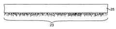
堆積基材は、液体懸濁体から取り外され、空気中で乾燥された。検査によって、堆積基材は、図4に示すように見え、伝導性カーボンナノチューブ23が、基材25の表面上に選択的に堆積されている。 The deposition substrate was removed from the liquid suspension and dried in air. By inspection, the deposited substrate appears as shown in FIG. 4, and the
分散溶液を用いた複数回のディッピングまたは複数回のコーティングは、カーボンナノチューブのより厚い層を形成する可能性がある。状況によっては、粒子採取ステップに移動する前に、粒子の厚い層を形成することが望ましいであろう。 Multiple dippings or multiple coatings with the dispersion solution can form a thicker layer of carbon nanotubes. In some situations, it may be desirable to form a thick layer of particles before moving on to the particle collection step.
粒子は、種々の方法を使用して採取されてもよい。適した方法は、図5によって示され、基材25に付着する粒子23は、スクレーパ31を使用して基材から掻き落とされ、図示する容器内に集められる。高圧スプレーまたは溶媒などを使用する他の方法を使用して、堆積基材から粒子を落としてもよい。The particles may be collected using various methods. A suitable method is illustrated by FIG. 5, in which
堆積表面から粒子を採取する、すなわち、粒子を除去するステップは、方法におけるオプションのステップとみなされるべきである。それは、方法の目的が、堆積表面に永久的にコーティングすることであるような状況が生じる場合があるからである。 The step of collecting particles from the deposition surface, ie removing the particles, should be considered an optional step in the method. This is because situations may arise where the purpose of the method is to permanently coat the deposition surface.
要約すると、本発明の方法は、伝導性粒子と低伝導性を含む液体懸濁体を調製するステップと、固体堆積表面を液体懸濁体に接触させるステップと、固体堆積表面を通して光を通過させるステップであって、それにより、堆積表面上に伝導性粒子を選択的に堆積させる、通過させるステップと、液体懸濁体と堆積表面を分離するステップと、堆積表面を乾燥させるステップと、任意選択で、伝導性粒子を堆積表面から除去するステップとを含む。固体堆積表面を液体懸濁体に接触させるステップは、先に述べた種々の方法、たとえば、粒子を、液体懸濁体を収容する容器の1つまたは複数の表面上に堆積させること、液体懸濁体をチューブまたは導管を通して流すこと、および、粒子をチューブ壁上に堆積させること、基材を液体懸濁体内に浸漬させることなどを含むことが理解されるであろう。 In summary, the method of the present invention comprises the steps of preparing a liquid suspension comprising conductive particles and low conductivity, contacting the solid deposition surface with the liquid suspension, and passing light through the solid deposition surface. Optionally, selectively depositing and passing conductive particles on the deposition surface, separating the liquid suspension from the deposition surface, and drying the deposition surface. And removing the conductive particles from the deposition surface. The step of bringing the solid deposition surface into contact with the liquid suspension can be performed in various ways as described above, for example, depositing particles on one or more surfaces of a container containing the liquid suspension, liquid suspension. It will be understood to include flowing the suspension through a tube or conduit, depositing particles on the tube wall, immersing the substrate in a liquid suspension, and the like.
堆積基材の表面を通して光を通過させるステップは、液体懸濁体に向けて光を通過させること、または、液体懸濁体を通して光を通過させることを意味する。先に示したように、前者が好ましい。光の波長は、堆積する粒子がそれについて有意の吸収帯を有する任意の波長であってよい。光源は、ランプ、LED、レーザを含む種々のデバイスから選択されてもよい。 Passing light through the surface of the deposition substrate means passing light toward the liquid suspension or passing light through the liquid suspension. As indicated above, the former is preferred. The wavelength of the light may be any wavelength that the deposited particles have a significant absorption band for it. The light source may be selected from a variety of devices including lamps, LEDs, and lasers.
上述した方法の実施例において、伝導性粒子は、堆積基材上に堆積され、伝導性粒子は、堆積表面から採取されるためか、または、堆積表面をコーティングするために選択された粒子である。しかし、非伝導性粒子が所望の種である用途が生じる場合がある。この場合、採取ステップは、上述した方法によって伝導性粒子が溶液から選択的に除去された後に、非伝導性粒子を溶液から採取することになるであろう。 In an embodiment of the method described above, the conductive particles are deposited on a deposition substrate, and the conductive particles are particles selected to be taken from the coating surface or to coat the deposition surface. . However, there may be applications where non-conductive particles are the desired species. In this case, the harvesting step would be to harvest the non-conductive particles from the solution after the conductive particles were selectively removed from the solution by the method described above.
先の説明では、堆積基材上に堆積する粒子は伝導性粒子である。非伝導性粒子が堆積基材上に選択的に堆積し、伝導性粒子を溶液内に残す方法が考案されてもよい。この変形は、上述した方法、すなわち、精選品を作るための光を使用したナノ粒子の選択的な分別の範囲内にあるものと考えられるべきである。 In the above description, the particles deposited on the deposition substrate are conductive particles. A method may be devised in which non-conductive particles are selectively deposited on the deposition substrate, leaving the conductive particles in solution. This variation should be considered within the scope of the selective separation of nanoparticles using the method described above, ie, light to make a selection.
本発明の種々のさらなる変更を、当業者が思いつくであろう。当技術分野がそれを通して進歩してきた原理およびその等価物に基本的に頼る本明細書の特定の教示からの全ての逸脱は、説明され、特許請求された本発明の範囲内に適切に存在すると考えられる。 Various further modifications of the invention will occur to those skilled in the art. All deviations from the specific teachings herein that fundamentally rely on the principles through which the art has progressed and equivalents thereof have been described and are properly within the scope of the claimed invention. Conceivable.
Claims (16)
Translated fromJapanese伝導性粒子と低伝導性とを含む液体懸濁体を調製するステップと、
固体堆積表面を前記液体懸濁体に接触させるステップと、
前記液体懸濁体内に光を通過させて前記粒子を照射し、前記伝導性粒子を前記堆積表面上に選択的に堆積させるステップとを含む方法。A method of separating conductive particles from low conductive particles,
Preparing a liquid suspension comprising conductive particles and low conductivity;
Contacting a solid deposition surface with the liquid suspension;
Passing light through the liquid suspension to irradiate the particles and selectively depositing the conductive particles on the deposition surface.
伝導性粒子と低伝導性とを含む液体懸濁体を調製するステップと、
固体堆積表面を前記液体懸濁体に接触させるステップと、
前記液体懸濁体内に光を通過させて前記粒子を照射し、前記非伝導性粒子を前記堆積表面上に選択的に堆積させるステップと、
前記液体懸濁体と前記堆積表面とを分離するステップと、
前記堆積表面を乾燥させるステップとを含む方法。A method of separating conductive particles from low conductive particles,
Preparing a liquid suspension comprising conductive particles and low conductivity;
Contacting a solid deposition surface with the liquid suspension;
Irradiating the particles with light passing through the liquid suspension to selectively deposit the non-conductive particles on the deposition surface;
Separating the liquid suspension from the deposition surface;
Drying said deposition surface.
Applications Claiming Priority (1)
| Application Number | Priority Date | Filing Date | Title |
|---|---|---|---|
| US11/973,568US20090090614A1 (en) | 2007-10-09 | 2007-10-09 | Thermophoretic fractionalization of small particles |
Publications (1)
| Publication Number | Publication Date |
|---|---|
| JP2009091241Atrue JP2009091241A (en) | 2009-04-30 |
Family
ID=40276156
Family Applications (1)
| Application Number | Title | Priority Date | Filing Date |
|---|---|---|---|
| JP2008262327APendingJP2009091241A (en) | 2007-10-09 | 2008-10-09 | Thermophoretic fractionalization of small particle |
Country Status (4)
| Country | Link |
|---|---|
| US (1) | US20090090614A1 (en) |
| EP (1) | EP2048114A3 (en) |
| JP (1) | JP2009091241A (en) |
| CN (1) | CN101428197A (en) |
Families Citing this family (5)
| Publication number | Priority date | Publication date | Assignee | Title |
|---|---|---|---|---|
| US8491768B2 (en) | 2010-06-23 | 2013-07-23 | International Business Machines Corporation | Method of purifying nanoparticles in a colloid |
| CN105149024B (en)* | 2015-09-16 | 2017-01-11 | 杭州电子科技大学 | Thermophoresis coupling subparticle sorter |
| CN108593910B (en)* | 2018-04-08 | 2022-06-21 | 国家纳米科学中心 | Particle detection system and method based on microsphere carrier |
| CN108593416B (en)* | 2018-04-08 | 2020-09-08 | 国家纳米科学中心 | Micro-nano particle detection system and method |
| CN114042547A (en)* | 2021-09-03 | 2022-02-15 | 浙江颀正环保科技有限公司 | Method and device for screening ultrafine particles by utilizing thermophoretic force |
Citations (9)
| Publication number | Priority date | Publication date | Assignee | Title |
|---|---|---|---|---|
| JP2004210608A (en)* | 2003-01-06 | 2004-07-29 | Japan Science & Technology Agency | Structure selection method of carbon nanotubes by light irradiation |
| US20050058590A1 (en)* | 2003-09-08 | 2005-03-17 | Nantero, Inc. | Spin-coatable liquid for formation of high purity nanotube films |
| US20050147373A1 (en)* | 2003-12-24 | 2005-07-07 | Yuegang Zhang | Controlling carbon nanotubes using optical traps |
| WO2005077827A1 (en)* | 2004-02-16 | 2005-08-25 | Japan Science And Technology Agency | Carbon nanotube structure-selective separation and surface fixation |
| US20060070920A1 (en)* | 2004-10-01 | 2006-04-06 | Yuegang Zhang | Application of static light to a fluid flow of CNTs for purposes of sorting the CNTs |
| JP2007123657A (en)* | 2005-10-31 | 2007-05-17 | Nec Corp | Semiconductor device and manufacturing method thereof |
| JP2007165678A (en)* | 2005-12-15 | 2007-06-28 | Nippon Telegr & Teleph Corp <Ntt> | Method and apparatus for manufacturing semiconductor device |
| JP2007169091A (en)* | 2005-12-20 | 2007-07-05 | Nippon Telegr & Teleph Corp <Ntt> | Diameter control method and diameter control apparatus for carbon nanotube |
| JP2008112163A (en)* | 2006-10-27 | 2008-05-15 | Furukawa Electric North America Inc | Selective deposition of carbon nanotubes on optical fibers |
Family Cites Families (6)
| Publication number | Priority date | Publication date | Assignee | Title |
|---|---|---|---|---|
| US6413781B1 (en)* | 1999-04-06 | 2002-07-02 | Massachusetts Institute Of Technology | Thermophoretic pump and concentrator |
| JP4653452B2 (en)* | 2003-10-24 | 2011-03-16 | 株式会社リコー | Fixing member, fixing device, and image forming apparatus |
| US7799196B2 (en)* | 2005-09-01 | 2010-09-21 | Micron Technology, Inc. | Methods and apparatus for sorting and/or depositing nanotubes |
| US20070084727A1 (en)* | 2005-10-14 | 2007-04-19 | Cummings Eric B | Coherent nonlinear chromatography and methods and devices thereof |
| ES2611996T3 (en)* | 2006-11-20 | 2017-05-11 | Nanotemper Technologies Gmbh | Rapid thermo-optical particle characterization |
| WO2009098079A1 (en)* | 2008-02-06 | 2009-08-13 | Ludwig-Maximilians-Universität München | Thermo-optical characterisation of nucleic acid molecules |
- 2007
- 2007-10-09USUS11/973,568patent/US20090090614A1/ennot_activeAbandoned
- 2008
- 2008-09-30EPEP08017235Apatent/EP2048114A3/ennot_activeWithdrawn
- 2008-10-08CNCNA2008101661650Apatent/CN101428197A/enactivePending
- 2008-10-09JPJP2008262327Apatent/JP2009091241A/enactivePending
Patent Citations (9)
| Publication number | Priority date | Publication date | Assignee | Title |
|---|---|---|---|---|
| JP2004210608A (en)* | 2003-01-06 | 2004-07-29 | Japan Science & Technology Agency | Structure selection method of carbon nanotubes by light irradiation |
| US20050058590A1 (en)* | 2003-09-08 | 2005-03-17 | Nantero, Inc. | Spin-coatable liquid for formation of high purity nanotube films |
| US20050147373A1 (en)* | 2003-12-24 | 2005-07-07 | Yuegang Zhang | Controlling carbon nanotubes using optical traps |
| WO2005077827A1 (en)* | 2004-02-16 | 2005-08-25 | Japan Science And Technology Agency | Carbon nanotube structure-selective separation and surface fixation |
| US20060070920A1 (en)* | 2004-10-01 | 2006-04-06 | Yuegang Zhang | Application of static light to a fluid flow of CNTs for purposes of sorting the CNTs |
| JP2007123657A (en)* | 2005-10-31 | 2007-05-17 | Nec Corp | Semiconductor device and manufacturing method thereof |
| JP2007165678A (en)* | 2005-12-15 | 2007-06-28 | Nippon Telegr & Teleph Corp <Ntt> | Method and apparatus for manufacturing semiconductor device |
| JP2007169091A (en)* | 2005-12-20 | 2007-07-05 | Nippon Telegr & Teleph Corp <Ntt> | Diameter control method and diameter control apparatus for carbon nanotube |
| JP2008112163A (en)* | 2006-10-27 | 2008-05-15 | Furukawa Electric North America Inc | Selective deposition of carbon nanotubes on optical fibers |
Also Published As
| Publication number | Publication date |
|---|---|
| EP2048114A2 (en) | 2009-04-15 |
| US20090090614A1 (en) | 2009-04-09 |
| EP2048114A3 (en) | 2009-07-29 |
| CN101428197A (en) | 2009-05-13 |
Similar Documents
| Publication | Publication Date | Title |
|---|---|---|
| Dong et al. | Springtail‐inspired superamphiphobic ordered nanohoodoo arrays with quasi‐doubly reentrant structures | |
| Zhang et al. | Spherical nanoparticle arrays with tunable nanogaps and their hydrophobicity enhanced rapid SERS detection by localized concentration of droplet evaporation | |
| Wen et al. | Wetting transition of condensed droplets on nanostructured superhydrophobic surfaces: coordination of surface properties and condensing conditions | |
| Long et al. | Low‐Cost fabrication of large‐area broccoli‐like multiscale micro‐and nanostructures for metallic super‐hydrophobic surfaces with ultralow water adhesion and superior anti‐frost ability | |
| CN102194633B (en) | Microgrid of transmissive electron microscope | |
| Song et al. | Biomimetic superstructures assembled from Au nanostars and nanospheres for efficient solar evaporation | |
| Boinovich et al. | Origins of thermodynamically stable superhydrophobicity of boron nitride nanotubes coatings | |
| JP2009091241A (en) | Thermophoretic fractionalization of small particle | |
| US20160146737A1 (en) | Substrate for surfaced enhanced raman scattering, fabrication method for the same and analyzing method using the same | |
| US8323553B2 (en) | Method for manufacturing a substrate with surface structure by employing photothermal effect | |
| Ruffino et al. | Self-organized patterned arrays of Au and Ag nanoparticles by thickness-dependent dewetting of template-confined films | |
| Feng et al. | Femtosecond laser irradiation induced heterojunctions between carbon nanofibers and silver nanowires for a flexible strain sensor | |
| KR101733861B1 (en) | Method of manufacturing a reduced-graphene oxide | |
| Baba et al. | Condensation behavior of hierarchical nano/microstructured surfaces inspired by euphorbia myrsinites | |
| Long et al. | Enhancing the Long‐Term Robustness of Dropwise Condensation on Nanostructured Superhydrophobic Surfaces by Introducing 3D Conical Microtextures Prepared by Femtosecond Laser | |
| CN104616954B (en) | A nickel-titanium amorphous alloy grid support film for transmission electron microscope | |
| György et al. | Effect of laser radiation on multi-wall carbon nanotubes: study of shell structure and immobilization process | |
| Khan et al. | Wettability modification of glass surfaces by deposition of carbon-based nanostructured films | |
| Zhao et al. | Preparation of a high‐performance thermally shrinkable polystyrene SERS substrate via Au@ Ag nanorods self‐assembled to detect pesticide residues | |
| Ruan et al. | Microcontact printing with laser direct writing carbonization for facile fabrication of carbon‐based ultrathin disk arrays and ordered Holey films | |
| CN110729162B (en) | A high-mesh microgrid carrier mesh for transmission electron microscope characterization and its preparation method | |
| JP2014048165A (en) | Destaticizer for analysis | |
| CN108793067B (en) | Non-thermal fusion of parallel nanowires and series structure forming and processing method thereof | |
| Xu et al. | A carbon nanotubes composite filter for removal of oil particles | |
| CN101481086A (en) | Non-damaged in situ construction method for nano-node |
Legal Events
| Date | Code | Title | Description |
|---|---|---|---|
| A621 | Written request for application examination | Free format text:JAPANESE INTERMEDIATE CODE: A621 Effective date:20090224 | |
| A131 | Notification of reasons for refusal | Free format text:JAPANESE INTERMEDIATE CODE: A131 Effective date:20120130 | |
| A601 | Written request for extension of time | Free format text:JAPANESE INTERMEDIATE CODE: A601 Effective date:20120427 | |
| A602 | Written permission of extension of time | Free format text:JAPANESE INTERMEDIATE CODE: A602 Effective date:20120507 | |
| A02 | Decision of refusal | Free format text:JAPANESE INTERMEDIATE CODE: A02 Effective date:20121030 |