JP2009090140A - Automatic syringe - Google Patents
Automatic syringeDownload PDFInfo
- Publication number
- JP2009090140A JP2009090140AJP2009017421AJP2009017421AJP2009090140AJP 2009090140 AJP2009090140 AJP 2009090140AJP 2009017421 AJP2009017421 AJP 2009017421AJP 2009017421 AJP2009017421 AJP 2009017421AJP 2009090140 AJP2009090140 AJP 2009090140A
- Authority
- JP
- Japan
- Prior art keywords
- self
- injector
- locking
- cartridge
- needle cover
- Prior art date
- Legal status (The legal status is an assumption and is not a legal conclusion. Google has not performed a legal analysis and makes no representation as to the accuracy of the status listed.)
- Granted
Links
- 239000003814drugSubstances0.000claimsabstractdescription57
- 238000003860storageMethods0.000claimsabstractdescription6
- 229940079593drugDrugs0.000claimsdescription46
- 238000002347injectionMethods0.000claimsdescription32
- 239000007924injectionSubstances0.000claimsdescription32
- 229940090047auto-injectorDrugs0.000claimsdescription19
- 230000004044responseEffects0.000claimsdescription18
- 230000006835compressionEffects0.000claimsdescription12
- 238000007906compressionMethods0.000claimsdescription12
- 230000007246mechanismEffects0.000claimsdescription11
- 230000000295complement effectEffects0.000claimsdescription9
- 239000000825pharmaceutical preparationSubstances0.000claimsdescription8
- 230000004913activationEffects0.000claimsdescription5
- 229940126534drug productDrugs0.000claims2
- 239000000306componentSubstances0.000description15
- 239000007788liquidSubstances0.000description11
- 235000013290Sagittaria latifoliaNutrition0.000description10
- 235000015246common arrowheadNutrition0.000description10
- 230000002093peripheral effectEffects0.000description9
- 229940127557pharmaceutical productDrugs0.000description6
- 239000007787solidSubstances0.000description5
- 230000014759maintenance of locationEffects0.000description4
- 230000000694effectsEffects0.000description3
- 230000004048modificationEffects0.000description3
- 238000012986modificationMethods0.000description3
- 239000008194pharmaceutical compositionSubstances0.000description3
- 230000002028prematureEffects0.000description3
- 125000006850spacer groupChemical group0.000description3
- 230000002411adverseEffects0.000description2
- 238000012377drug deliveryMethods0.000description2
- 239000000463materialSubstances0.000description2
- 238000007639printingMethods0.000description2
- 230000001681protective effectEffects0.000description2
- 230000000717retained effectEffects0.000description2
- 238000005096rolling processMethods0.000description2
- 230000000007visual effectEffects0.000description2
- 208000032484Accidental exposure to productDiseases0.000description1
- 229910001369BrassInorganic materials0.000description1
- 206010020751HypersensitivityDiseases0.000description1
- 231100000818accidental exposureToxicity0.000description1
- 238000009825accumulationMethods0.000description1
- 230000009471actionEffects0.000description1
- 230000003213activating effectEffects0.000description1
- 208000026935allergic diseaseDiseases0.000description1
- 230000007815allergyEffects0.000description1
- 230000002052anaphylactic effectEffects0.000description1
- 239000000729antidoteSubstances0.000description1
- 230000009286beneficial effectEffects0.000description1
- 239000010951brassSubstances0.000description1
- 238000006243chemical reactionMethods0.000description1
- 150000001875compoundsChemical class0.000description1
- 238000010276constructionMethods0.000description1
- 230000007812deficiencyEffects0.000description1
- 238000010586diagramMethods0.000description1
- AAOVKJBEBIDNHE-UHFFFAOYSA-NdiazepamChemical compoundN=1CC(=O)N(C)C2=CC=C(Cl)C=C2C=1C1=CC=CC=C1AAOVKJBEBIDNHE-UHFFFAOYSA-N0.000description1
- 238000001647drug administrationMethods0.000description1
- 239000000428dustSubstances0.000description1
- 238000005516engineering processMethods0.000description1
- 238000010304firingMethods0.000description1
- 239000012530fluidSubstances0.000description1
- 239000011521glassSubstances0.000description1
- 238000007918intramuscular administrationMethods0.000description1
- 238000002372labellingMethods0.000description1
- 238000004519manufacturing processMethods0.000description1
- 239000002184metalSubstances0.000description1
- 239000000203mixtureSubstances0.000description1
- 239000003958nerve gasSubstances0.000description1
- 210000002445nippleAnatomy0.000description1
- 238000011022operating instructionMethods0.000description1
- 230000035515penetrationEffects0.000description1
- 239000008177pharmaceutical agentSubstances0.000description1
- 239000005426pharmaceutical componentSubstances0.000description1
- 230000036316preloadEffects0.000description1
- 238000002360preparation methodMethods0.000description1
- 238000003825pressingMethods0.000description1
- 230000002787reinforcementEffects0.000description1
- 230000003014reinforcing effectEffects0.000description1
- 230000006641stabilisationEffects0.000description1
- 238000011105stabilizationMethods0.000description1
- 239000007858starting materialSubstances0.000description1
- 238000010254subcutaneous injectionMethods0.000description1
- 239000007929subcutaneous injectionSubstances0.000description1
- 239000000126substanceSubstances0.000description1
- 229920002994synthetic fiberPolymers0.000description1
- 231100000167toxic agentToxicity0.000description1
- 239000003440toxic substanceSubstances0.000description1
Images


Classifications
- A—HUMAN NECESSITIES
- A61—MEDICAL OR VETERINARY SCIENCE; HYGIENE
- A61M—DEVICES FOR INTRODUCING MEDIA INTO, OR ONTO, THE BODY; DEVICES FOR TRANSDUCING BODY MEDIA OR FOR TAKING MEDIA FROM THE BODY; DEVICES FOR PRODUCING OR ENDING SLEEP OR STUPOR
- A61M5/00—Devices for bringing media into the body in a subcutaneous, intra-vascular or intramuscular way; Accessories therefor, e.g. filling or cleaning devices, arm-rests
- A61M5/178—Syringes
- A61M5/31—Details
- A61M5/32—Needles; Details of needles pertaining to their connection with syringe or hub; Accessories for bringing the needle into, or holding the needle on, the body; Devices for protection of needles
- A61M5/3205—Apparatus for removing or disposing of used needles or syringes, e.g. containers; Means for protection against accidental injuries from used needles
- A61M5/321—Means for protection against accidental injuries by used needles
- A61M5/3243—Means for protection against accidental injuries by used needles being axially-extensible, e.g. protective sleeves coaxially slidable on the syringe barrel
- A61M5/3271—Means for protection against accidental injuries by used needles being axially-extensible, e.g. protective sleeves coaxially slidable on the syringe barrel with guiding tracks for controlled sliding of needle protective sleeve from needle exposing to needle covering position
- A—HUMAN NECESSITIES
- A61—MEDICAL OR VETERINARY SCIENCE; HYGIENE
- A61M—DEVICES FOR INTRODUCING MEDIA INTO, OR ONTO, THE BODY; DEVICES FOR TRANSDUCING BODY MEDIA OR FOR TAKING MEDIA FROM THE BODY; DEVICES FOR PRODUCING OR ENDING SLEEP OR STUPOR
- A61M5/00—Devices for bringing media into the body in a subcutaneous, intra-vascular or intramuscular way; Accessories therefor, e.g. filling or cleaning devices, arm-rests
- A61M5/178—Syringes
- A61M5/20—Automatic syringes, e.g. with automatically actuated piston rod, with automatic needle injection, filling automatically
- A61M5/2033—Spring-loaded one-shot injectors with or without automatic needle insertion
- A—HUMAN NECESSITIES
- A61—MEDICAL OR VETERINARY SCIENCE; HYGIENE
- A61M—DEVICES FOR INTRODUCING MEDIA INTO, OR ONTO, THE BODY; DEVICES FOR TRANSDUCING BODY MEDIA OR FOR TAKING MEDIA FROM THE BODY; DEVICES FOR PRODUCING OR ENDING SLEEP OR STUPOR
- A61M5/00—Devices for bringing media into the body in a subcutaneous, intra-vascular or intramuscular way; Accessories therefor, e.g. filling or cleaning devices, arm-rests
- A61M5/178—Syringes
- A61M5/31—Details
- A61M5/315—Pistons; Piston-rods; Guiding, blocking or restricting the movement of the rod or piston; Appliances on the rod for facilitating dosing ; Dosing mechanisms
- A61M5/31596—Pistons; Piston-rods; Guiding, blocking or restricting the movement of the rod or piston; Appliances on the rod for facilitating dosing ; Dosing mechanisms comprising means for injection of two or more media, e.g. by mixing
- A—HUMAN NECESSITIES
- A61—MEDICAL OR VETERINARY SCIENCE; HYGIENE
- A61M—DEVICES FOR INTRODUCING MEDIA INTO, OR ONTO, THE BODY; DEVICES FOR TRANSDUCING BODY MEDIA OR FOR TAKING MEDIA FROM THE BODY; DEVICES FOR PRODUCING OR ENDING SLEEP OR STUPOR
- A61M5/00—Devices for bringing media into the body in a subcutaneous, intra-vascular or intramuscular way; Accessories therefor, e.g. filling or cleaning devices, arm-rests
- A61M5/178—Syringes
- A61M5/31—Details
- A61M5/32—Needles; Details of needles pertaining to their connection with syringe or hub; Accessories for bringing the needle into, or holding the needle on, the body; Devices for protection of needles
- A61M5/3205—Apparatus for removing or disposing of used needles or syringes, e.g. containers; Means for protection against accidental injuries from used needles
- A61M5/321—Means for protection against accidental injuries by used needles
- A61M5/3243—Means for protection against accidental injuries by used needles being axially-extensible, e.g. protective sleeves coaxially slidable on the syringe barrel
- A61M5/3245—Constructional features thereof, e.g. to improve manipulation or functioning
- A—HUMAN NECESSITIES
- A61—MEDICAL OR VETERINARY SCIENCE; HYGIENE
- A61M—DEVICES FOR INTRODUCING MEDIA INTO, OR ONTO, THE BODY; DEVICES FOR TRANSDUCING BODY MEDIA OR FOR TAKING MEDIA FROM THE BODY; DEVICES FOR PRODUCING OR ENDING SLEEP OR STUPOR
- A61M5/00—Devices for bringing media into the body in a subcutaneous, intra-vascular or intramuscular way; Accessories therefor, e.g. filling or cleaning devices, arm-rests
- A61M5/178—Syringes
- A61M5/20—Automatic syringes, e.g. with automatically actuated piston rod, with automatic needle injection, filling automatically
- A61M2005/2006—Having specific accessories
- A61M2005/2013—Having specific accessories triggering of discharging means by contact of injector with patient body
- A—HUMAN NECESSITIES
- A61—MEDICAL OR VETERINARY SCIENCE; HYGIENE
- A61M—DEVICES FOR INTRODUCING MEDIA INTO, OR ONTO, THE BODY; DEVICES FOR TRANSDUCING BODY MEDIA OR FOR TAKING MEDIA FROM THE BODY; DEVICES FOR PRODUCING OR ENDING SLEEP OR STUPOR
- A61M5/00—Devices for bringing media into the body in a subcutaneous, intra-vascular or intramuscular way; Accessories therefor, e.g. filling or cleaning devices, arm-rests
- A61M5/178—Syringes
- A61M5/20—Automatic syringes, e.g. with automatically actuated piston rod, with automatic needle injection, filling automatically
- A61M2005/206—With automatic needle insertion
- A—HUMAN NECESSITIES
- A61—MEDICAL OR VETERINARY SCIENCE; HYGIENE
- A61M—DEVICES FOR INTRODUCING MEDIA INTO, OR ONTO, THE BODY; DEVICES FOR TRANSDUCING BODY MEDIA OR FOR TAKING MEDIA FROM THE BODY; DEVICES FOR PRODUCING OR ENDING SLEEP OR STUPOR
- A61M5/00—Devices for bringing media into the body in a subcutaneous, intra-vascular or intramuscular way; Accessories therefor, e.g. filling or cleaning devices, arm-rests
- A61M5/178—Syringes
- A61M5/20—Automatic syringes, e.g. with automatically actuated piston rod, with automatic needle injection, filling automatically
- A61M2005/2073—Automatic syringes, e.g. with automatically actuated piston rod, with automatic needle injection, filling automatically preventing premature release, e.g. by making use of a safety lock
- A—HUMAN NECESSITIES
- A61—MEDICAL OR VETERINARY SCIENCE; HYGIENE
- A61M—DEVICES FOR INTRODUCING MEDIA INTO, OR ONTO, THE BODY; DEVICES FOR TRANSDUCING BODY MEDIA OR FOR TAKING MEDIA FROM THE BODY; DEVICES FOR PRODUCING OR ENDING SLEEP OR STUPOR
- A61M5/00—Devices for bringing media into the body in a subcutaneous, intra-vascular or intramuscular way; Accessories therefor, e.g. filling or cleaning devices, arm-rests
- A61M5/178—Syringes
- A61M5/31—Details
- A61M2005/3125—Details specific display means, e.g. to indicate dose setting
- A61M2005/3126—Specific display means related to dosing
- A—HUMAN NECESSITIES
- A61—MEDICAL OR VETERINARY SCIENCE; HYGIENE
- A61M—DEVICES FOR INTRODUCING MEDIA INTO, OR ONTO, THE BODY; DEVICES FOR TRANSDUCING BODY MEDIA OR FOR TAKING MEDIA FROM THE BODY; DEVICES FOR PRODUCING OR ENDING SLEEP OR STUPOR
- A61M5/00—Devices for bringing media into the body in a subcutaneous, intra-vascular or intramuscular way; Accessories therefor, e.g. filling or cleaning devices, arm-rests
- A61M5/178—Syringes
- A61M5/31—Details
- A61M5/32—Needles; Details of needles pertaining to their connection with syringe or hub; Accessories for bringing the needle into, or holding the needle on, the body; Devices for protection of needles
- A61M5/3205—Apparatus for removing or disposing of used needles or syringes, e.g. containers; Means for protection against accidental injuries from used needles
- A61M5/321—Means for protection against accidental injuries by used needles
- A61M5/3243—Means for protection against accidental injuries by used needles being axially-extensible, e.g. protective sleeves coaxially slidable on the syringe barrel
- A61M5/3245—Constructional features thereof, e.g. to improve manipulation or functioning
- A61M2005/3247—Means to impede repositioning of protection sleeve from needle covering to needle uncovering position
- A—HUMAN NECESSITIES
- A61—MEDICAL OR VETERINARY SCIENCE; HYGIENE
- A61M—DEVICES FOR INTRODUCING MEDIA INTO, OR ONTO, THE BODY; DEVICES FOR TRANSDUCING BODY MEDIA OR FOR TAKING MEDIA FROM THE BODY; DEVICES FOR PRODUCING OR ENDING SLEEP OR STUPOR
- A61M2205/00—General characteristics of the apparatus
- A61M2205/58—Means for facilitating use, e.g. by people with impaired vision
- A61M2205/586—Ergonomic details therefor, e.g. specific ergonomics for left or right-handed users
- A—HUMAN NECESSITIES
- A61—MEDICAL OR VETERINARY SCIENCE; HYGIENE
- A61M—DEVICES FOR INTRODUCING MEDIA INTO, OR ONTO, THE BODY; DEVICES FOR TRANSDUCING BODY MEDIA OR FOR TAKING MEDIA FROM THE BODY; DEVICES FOR PRODUCING OR ENDING SLEEP OR STUPOR
- A61M5/00—Devices for bringing media into the body in a subcutaneous, intra-vascular or intramuscular way; Accessories therefor, e.g. filling or cleaning devices, arm-rests
- A61M5/178—Syringes
- A61M5/24—Ampoule syringes, i.e. syringes with needle for use in combination with replaceable ampoules or carpules, e.g. automatic
- A61M5/2455—Ampoule syringes, i.e. syringes with needle for use in combination with replaceable ampoules or carpules, e.g. automatic with sealing means to be broken or opened
- A61M5/2459—Ampoule syringes, i.e. syringes with needle for use in combination with replaceable ampoules or carpules, e.g. automatic with sealing means to be broken or opened upon internal pressure increase, e.g. pierced or burst
- A—HUMAN NECESSITIES
- A61—MEDICAL OR VETERINARY SCIENCE; HYGIENE
- A61M—DEVICES FOR INTRODUCING MEDIA INTO, OR ONTO, THE BODY; DEVICES FOR TRANSDUCING BODY MEDIA OR FOR TAKING MEDIA FROM THE BODY; DEVICES FOR PRODUCING OR ENDING SLEEP OR STUPOR
- A61M5/00—Devices for bringing media into the body in a subcutaneous, intra-vascular or intramuscular way; Accessories therefor, e.g. filling or cleaning devices, arm-rests
- A61M5/178—Syringes
- A61M5/31—Details
- A61M5/3129—Syringe barrels
- A—HUMAN NECESSITIES
- A61—MEDICAL OR VETERINARY SCIENCE; HYGIENE
- A61M—DEVICES FOR INTRODUCING MEDIA INTO, OR ONTO, THE BODY; DEVICES FOR TRANSDUCING BODY MEDIA OR FOR TAKING MEDIA FROM THE BODY; DEVICES FOR PRODUCING OR ENDING SLEEP OR STUPOR
- A61M5/00—Devices for bringing media into the body in a subcutaneous, intra-vascular or intramuscular way; Accessories therefor, e.g. filling or cleaning devices, arm-rests
- A61M5/178—Syringes
- A61M5/31—Details
- A61M5/32—Needles; Details of needles pertaining to their connection with syringe or hub; Accessories for bringing the needle into, or holding the needle on, the body; Devices for protection of needles
- A61M5/3205—Apparatus for removing or disposing of used needles or syringes, e.g. containers; Means for protection against accidental injuries from used needles
- A61M5/321—Means for protection against accidental injuries by used needles
- A61M5/3243—Means for protection against accidental injuries by used needles being axially-extensible, e.g. protective sleeves coaxially slidable on the syringe barrel
- A61M5/326—Fully automatic sleeve extension, i.e. in which triggering of the sleeve does not require a deliberate action by the user
Landscapes
- Health & Medical Sciences (AREA)
- Engineering & Computer Science (AREA)
- Heart & Thoracic Surgery (AREA)
- Vascular Medicine (AREA)
- Anesthesiology (AREA)
- Biomedical Technology (AREA)
- Hematology (AREA)
- Life Sciences & Earth Sciences (AREA)
- Animal Behavior & Ethology (AREA)
- General Health & Medical Sciences (AREA)
- Public Health (AREA)
- Veterinary Medicine (AREA)
- Environmental & Geological Engineering (AREA)
- Infusion, Injection, And Reservoir Apparatuses (AREA)
Abstract
Description
Translated fromJapanese(関連出願の相互参照)
本願は、2004年8月6日に出願された米国特許仮出願第60/599054号に関し、その優先権を主張する。なお、該仮出願の全体を特に参照により本願に援用する。(Cross-reference of related applications)
This application claims priority to US Provisional Application No. 60 / 59,054 filed Aug. 6, 2004. The entire provisional application is specifically incorporated herein by reference.
(発明の背景)
(1.本発明の分野)
本発明は、医薬品を注射部位に送達する自動注射器若しくは自己注射器に関する。詳細には、本発明は、使用後にユーザが自己注射器の針と接触するのを防ぐための針カバー機構を有する自己注射器を対象とする。針カバー機構は、自己注射器の始動前には係止された位置で保持される。注射後、ユーザが針に接近できないように、針カバー機構は、係止された展開位置で保持される。(Background of the invention)
(1. Field of the Invention)
The present invention relates to an auto-injector or auto-injector that delivers a pharmaceutical product to an injection site. Specifically, the present invention is directed to a self-injector having a needle cover mechanism for preventing a user from contacting the self-injector needle after use. The needle cover mechanism is held in the locked position before the self-injector is started. The needle cover mechanism is held in the locked deployed position so that the user cannot access the needle after injection.
本発明は、また、1部品の成型コレットを含むパワーパックを有する自己注射器も対象とする。成型コレットは、汎用性を高めながら、製造される全コンポーネント数を削減する。成型コレットは、多様なサイズのカートリッジ、様々なサイズの針とともに使用することができ、また、成型コレットを使用して、送達される医薬品の投与量を多様なものにすることができる。 The present invention is also directed to a self-injector having a power pack that includes a one-piece molded collet. Molded collets reduce the total number of components produced while increasing versatility. Molded collets can be used with various sized cartridges, various sized needles, and molded collets can be used to vary the dose of pharmaceutical agent delivered.
(2.関連技術の説明)
自動注射器又は自己注射器は、通常は緊急事態に、予め計測された1回用量の医薬組成物をユーザが皮下又は筋肉内に自己投与できるように設計されたデバイスである。自動注射器は、例えば、アナフィラキシー(重度のアレルギー)反応を処置するために、また、化学神経ガスなどの特定の毒物のための解毒剤及びジアゼパン(diazepan)などの様々な薬物組成物を投与するために使用される。(2. Explanation of related technology)
An auto-injector or self-injector is a device designed to allow a user to self-administer a pre-measured single dose pharmaceutical composition subcutaneously or intramuscularly, usually in an emergency situation. Automatic syringes, for example, to treat anaphylactic (severe allergy) reactions and to administer various drug compositions such as antidote for certain toxicants such as chemical nerve gases and diazepan Used for.
典型的な自己注射器は、ハウジングを有し、その内側にカートリッジが存在する。カートリッジは、医薬組成物又はそれらの構成成分が入った1つ若しくはいくつかのチャンバを有し、針アセンブリに取り付けられるように適合されている。カートリッジは、予め混合された液体医薬品、又は注射前に混合される固体医薬品と液体とを保持することができる。ハウジングには、例えば圧縮されたばねなどの、蓄積エネルギー源を備えた作動アセンブリが設けられる。作動アセンブリを始動すると、一連の動きが引き起こされ、それによって針が自己注射器からユーザへと拡張し、その結果、医薬品化合物が針を通じてユーザへと送り込まれる。医薬品の1回用量が注射部位に送達された後、針は、拡張位置にとどまる。自己注射器が医薬組成物の複数の構成成分を別個の封止区画に含むように設計されたタイプのものである場合、作動アセンブリが始動されたときに構成成分を強制混合する構造を含めることができる。 A typical self-injector has a housing with a cartridge inside. The cartridge has one or several chambers containing the pharmaceutical composition or components thereof and is adapted to be attached to the needle assembly. The cartridge can hold a pre-mixed liquid pharmaceutical or a solid pharmaceutical and liquid mixed prior to injection. The housing is provided with an actuating assembly with a stored energy source, for example a compressed spring. Activating the actuation assembly causes a series of movements that cause the needle to expand from the self-injector to the user so that the pharmaceutical compound is delivered to the user through the needle. After a single dose of pharmaceutical product has been delivered to the injection site, the needle remains in the expanded position. If the auto-injector is of a type designed to include multiple components of the pharmaceutical composition in separate sealed compartments, it may include a structure that forcibly mixes the components when the actuation assembly is started it can.
自己注射器の操作の前後に針から適切に保護するカバーを備えた自己注射器が必要である。Wilmotらの米国特許第5295965号は、使用後に尖鋭物からの保護をもたらす、自己注射器のための外部カバー部材を開示している。該カバー部材は、使用後にユーザから針が見えないように、自己注射器の作動後に展開される。使用後、針が針カバーの開口部を通って再び展開されることがないように、カバー部材の位置は、自己注射器ボディに対してずらされる。 There is a need for a self-injector with a cover that provides adequate protection from the needle before and after operation of the self-injector. US Pat. No. 5,295,965 to Wilmot et al. Discloses an outer cover member for a self-injector that provides protection from sharp objects after use. The cover member is deployed after actuation of the self-injector so that the needle is not visible to the user after use. After use, the position of the cover member is shifted relative to the self-injector body so that the needle is not deployed again through the opening of the needle cover.
Kaplanの米国特許第6767336号は、自己注射器のためのカバーを開示している。Kaplanは、コンポーネントを削減するために、自己注射器のための外側ハウジングを排除している。カバーは、カートリッジホルダスリーブの外部に固定される。カートリッジホルダスリーブは、カバーの上でラッチを受けるようにサイズ設定された、いくつかのスロットを含む。自己注射器が始動されるときには、カートリッジホルダスリーブ内のカートリッジがラッチを陥凹部から解放し、その結果、カバーがばねの付勢を受けて自由に移動する。Kaplanによって開示されるカバーがカートリッジホルダスリーブの外部に配置されるので、ユーザが自己注射器の操作の間カバーを握持することが可能である。したがって、ユーザは、各スロットからラッチが解放されるのを妨げることがあり、その結果、カバーが適切に展開されるのを妨げる虞がある。このことが、カートリッジ内のカートリッジの動きを妨害し、したがって針が注射部位に到達する前に医薬品が針を通って分注される虞がある。これらの欠陥を克服するには、より大きなトリガ力が必要となる。カバーの展開中にラッチが解放されるときには、ラッチは、外側に向かって付勢される。この展開によって、ユーザが挟まれる、又は他の何らかの形で傷つけられる可能性がある。 Kaplan US Pat. No. 6,767,336 discloses a cover for a self-injector. Kaplan has eliminated the outer housing for self-injectors to reduce components. The cover is fixed to the outside of the cartridge holder sleeve. The cartridge holder sleeve includes a number of slots sized to receive a latch on the cover. When the self-injector is activated, the cartridge in the cartridge holder sleeve releases the latch from the recess, so that the cover moves freely under the bias of the spring. The cover disclosed by Kaplan is located outside the cartridge holder sleeve so that the user can grip the cover during operation of the self-injector. Thus, the user may prevent the latch from being released from each slot and, as a result, may prevent the cover from being properly deployed. This interferes with the movement of the cartridge within the cartridge, so that the medication may be dispensed through the needle before the needle reaches the injection site. To overcome these deficiencies, a greater triggering force is required. When the latch is released during deployment of the cover, the latch is biased outward. This deployment can pinch the user or otherwise injure him.
薬物の送達前にカバーが展開する場合、ユーザが医薬品の適正な1回用量を受け取れないことがあるので、生命を脅かす虞のある事故が起こりかねない。自己注射器の使用前には変位できないような、固定されたカバーが必要である。また、万一ユーザと接触した場合に、自己注射器の操作を妨げない、又は操作に悪影響を及ぼさないカバーが必要である。また、人が誤って針に刺されることがないように、自己注射器の使用後に針が露出しないようにカバーが拡張位置で係止されることが望ましい。また、カバーの誤展開を防ぐために、操作者との接触から保護された係止/展開機構を有するカバー部材があることが望ましい。 If the cover is deployed before delivery of the drug, the user may not receive the correct single dose of the drug, which can lead to a life-threatening accident. There is a need for a fixed cover that cannot be displaced prior to use of the self-injector. Also, a cover that does not interfere with the operation of the self-injector or adversely affect the operation in the event of contact with the user is required. It is also desirable that the cover is locked in the extended position so that the needle is not exposed after use of the self-injector so that a person is not accidentally pierced by the needle. Also, it is desirable to have a cover member having a locking / deployment mechanism that is protected from contact with the operator to prevent erroneous deployment of the cover.
(発明の要旨)
本発明の一態様は、所定の投与量の医薬品を分注する自己注射器に関する。医薬品は、自己投与することができ、また介護人が投与することもできる。自己注射器は、ハウジングを含む。ハウジングが、より人間工学的になるように、卵形(oval)又は楕円形(elliptical)であることが好ましい。卵形は、自己注射器がテーブル若しくは平らな表面を転がり落ちるのを防ぎながら、取扱説明書を印刷するためのより大きな表面積を提供する。カートリッジ容器がハウジング内に配置される。カートリッジがカートリッジ容器内で受けられる。カートリッジは、その中に少なくとも1つの開口部を有し、医薬品を含む。医薬品は、後方をプランジャによって密閉される。カートリッジは、それを通じて医薬品を分注するための針アセンブリを含む。カートリッジは、カートリッジ容器内を、保管位置から、針がカートリッジ容器から拡張して医薬品の1回用量を投与できるようになる操作位置へと進められる。作動アセンブリ又はパワーパックは、蓄積エネルギー源を提供しており、該蓄積エネルギー源を解放してカートリッジ内でプランジャを駆動し、針アセンブリを通じて医薬品をユーザへと分注することができ、また始動時に針に接近できるようにする。(Summary of the Invention)
One embodiment of the present invention relates to an auto-injector that dispenses a predetermined dose of a pharmaceutical product. The medication can be self-administered or can be administered by a caregiver. The self-injector includes a housing. It is preferred that the housing is oval or elliptical so that it is more ergonomic. The oval provides a larger surface area for printing instruction manuals while preventing the self-injector from rolling down the table or flat surface. A cartridge container is disposed in the housing. A cartridge is received in the cartridge container. The cartridge has at least one opening therein and contains a medicament. The medicine is sealed behind by a plunger. The cartridge includes a needle assembly for dispensing medication therethrough. The cartridge is advanced through the cartridge container from the storage position to an operating position where the needle extends from the cartridge container to allow a single dose of pharmaceutical product to be dispensed. The actuating assembly or power pack provides a source of stored energy that can be released to drive the plunger within the cartridge to dispense the medication to the user through the needle assembly, and also at start-up Allow access to the needle.
自己注射器の他の態様は、ハウジング内で受けられる針カバーの提供である。針カバーは、自己注射器の使用後にユーザが不慮に針にさらされないように遮り、尖鋭物から保護している。理論的には、針がユーザに刺さって初めてカバーが展開するので、針カバーの操作は、フェイルセーフである。操作中、カートリッジの針は、医薬品の1回用量を分注できるように、針カバーの開口部を通って拡張する。自己注射器の使用後、針カバーが引込んで針を露出させるのを防ぐために、針カバーは、係止された位置で保持される。本発明の他の態様によれば、針カバーは、自己注射器始動前の係止された格納位置にあり、したがって使用前には小型のデバイス構成を維持する。本発明の他の態様によれば、自己注射器に付随する作動力は、針カバーには伝わらない。 Another aspect of the self-injector is the provision of a needle cover received within the housing. The needle cover shields the user from accidental exposure to the needle after use of the self-injector and protects it from sharp objects. Theoretically, the operation of the needle cover is fail-safe because the cover is unfolded only after the needle has stabbed the user. During operation, the needle of the cartridge expands through the opening in the needle cover so that a single dose of medication can be dispensed. After use of the self-injector, the needle cover is held in a locked position to prevent the needle cover from retracting and exposing the needle. According to another aspect of the invention, the needle cover is in a locked retracted position prior to starting the self-injector, thus maintaining a compact device configuration prior to use. According to another aspect of the invention, the actuation force associated with the self-injector is not transmitted to the needle cover.
本発明の他の態様によれば、自己注射器は、針カバーを第1の係止位置で保持する第1の係止アセンブリを有する。第1の係止アセンブリは、カートリッジ容器の上に配置することができる。第1の係止アセンブリは、カートリッジ容器又は針カバーに回転自在に連結された少なくとも1つの係止歯を含むことができる。各係止歯は、針カバーに解放可能に係合し、針カバー又はカートリッジ容器上の表面と接触するように構築且つ配置された係止表面を含む。各係止歯は、容器又はカバーに連結された別個のコンポーネントとして形成することができる。係止歯を針カバー又はカートリッジの一体部分として形成できることが企図される。係止歯のばねの力が、係止表面を付勢して針カバーと接触させる。ばねの力は、係止歯のばね部分によって提供することができる。ばねの力は、また、係止表面を付勢して針カバーと接触させる別個のばねアセンブリによって提供することもできる。各係止歯がカートリッジ容器に回転自在に連結されることが好ましい。各係止歯は、カートリッジ容器内のカートリッジの動きに応答して回転する。また、係止歯がコレット又はパワーパックの動きに応答して回転できることも企図される。通常、係止歯がカートリッジの動きに応答して回転するときには、係止表面は、回転して針カバーと接触しなくなる。ばねの力、並びに係止歯によってカートリッジに及ぼされる力は、カートリッジ内のダイアフラムの過早破裂及び医薬品の過早投与を避けるために、注射操作の間のカートリッジの運動を無視できる程度又は最小限しか妨げないように制御される。 In accordance with another aspect of the invention, the self-injector has a first locking assembly that holds the needle cover in a first locking position. The first locking assembly can be disposed on the cartridge container. The first locking assembly can include at least one locking tooth rotatably coupled to the cartridge container or needle cover. Each locking tooth includes a locking surface constructed and arranged to releasably engage the needle cover and contact a surface on the needle cover or cartridge container. Each locking tooth can be formed as a separate component connected to the container or cover. It is contemplated that the locking teeth can be formed as an integral part of the needle cover or cartridge. The force of the locking tooth spring biases the locking surface into contact with the needle cover. The spring force can be provided by the spring portion of the locking tooth. The spring force can also be provided by a separate spring assembly that biases the locking surface into contact with the needle cover. Each locking tooth is preferably rotatably connected to the cartridge container. Each locking tooth rotates in response to movement of the cartridge within the cartridge container. It is also contemplated that the locking teeth can rotate in response to the movement of the collet or power pack. Normally, when the locking tooth rotates in response to the movement of the cartridge, the locking surface rotates and does not contact the needle cover. The force of the spring and the force exerted on the cartridge by the locking teeth is such that the movement of the cartridge during the injection operation is negligible or minimal to avoid premature rupture of the diaphragm in the cartridge and premature administration of the drug. It is controlled so as not to interfere.
針カバーは、ばね付勢されていて、第1の係止アセンブリが解放された後、該針カバーがハウジングから外側に向かって付勢され、露出した針を覆う。本発明の他の態様によれば、自己注射器は、針カバーを第2の係止位置で保持する第2の係止アセンブリを有する。第2の係止アセンブリは、カートリッジ容器、外側ボディ、又はカバー部材上に配置することができる。第2の係止アセンブリは、好ましくはカートリッジ容器に連結された、少なくとも1つの係止アーム又はウイングを含むことができる。各係止アームは、針カバーが第1の係止位置から第2の係止位置へと移動するにつれて係止アームをカートリッジ容器に当てて一時的に圧迫できるように、カートリッジ容器から離隔されている。各係止アームは、針カバーが係止された拡張位置にあるときに該針カバーに係合するための係止表面を有する。各係止アームは、厚いストラット部分と薄いストラット部分とを有し、厚いストラット部分が外側に湾曲し、薄いストラット部分が内側に湾曲している。この構造は、カートリッジ容器に加わる応力を低減するために、標準の非圧迫状態で係止アームを支持する。この構造は、また、カバー部材の滑らかな展開を可能にする。さらに、この配置は、厚いストラット部分が曲がって安定な状態になるのを保証する。このことが、カバー部材が後方に移動して格納位置にくるのを防ぐためのより強力な係止を生み出す。薄いストラット部分の内側に湾曲した性質によって、厚い部分を制御された形で曲げて、安定な状態にすることができる。さらに、厚いストラット部分の外側に湾曲した形状は、拡張位置にあるカバー部材のフェイルセーフ係止をもたらす。万一薄いストラットが破断した場合でも、厚いストラット部分がカバー部材に係合して、該カバー部材を拡張した係止位置で支持することになる。 The needle cover is spring biased so that after the first locking assembly is released, the needle cover is biased outward from the housing to cover the exposed needle. In accordance with another aspect of the invention, the self-injector has a second locking assembly that holds the needle cover in a second locking position. The second locking assembly can be disposed on the cartridge container, the outer body, or the cover member. The second locking assembly can include at least one locking arm or wing, preferably coupled to the cartridge container. Each locking arm is spaced from the cartridge container so that the locking arm can be temporarily pressed against the cartridge container as the needle cover moves from the first locking position to the second locking position. Yes. Each locking arm has a locking surface for engaging the needle cover when the needle cover is in the locked extended position. Each locking arm has a thick strut portion and a thin strut portion, with the thick strut portion curved outward and the thin strut portion curved inward. This structure supports the locking arm in a standard non-squeezed state to reduce stress on the cartridge container. This structure also allows for smooth deployment of the cover member. In addition, this arrangement ensures that the thick strut portions bend and become stable. This creates a stronger lock to prevent the cover member from moving backwards into the retracted position. Due to the inwardly curved nature of the thin strut portion, the thick portion can be bent in a controlled manner to a stable state. In addition, the outwardly curved shape of the thick strut portion provides a failsafe locking of the cover member in the extended position. Even if the thin strut breaks, the thick strut portion engages with the cover member and supports the cover member in the expanded locking position.
カートリッジ容器は、それから外側に延びる少なくとも1つのレッジをさらに含むことができる。各レッジは、針カバーが拡張位置にあるときに該針カバーの開口部の縁部に係合してカートリッジ容器に対する該針カバーの移動を制限するように構築且つ配置される。カートリッジ容器上のレッジが開口部の縁部に係合するときには、針カバーの外側への移動が制限される。第2の係止アセンブリは、針カバーの内側への移動を制限する。針カバー及びカートリッジ容器には、開口部が形成されている。自己注射器の始動前にそれらの開口部が位置合わせされているときには、ユーザは、ハウジング及び開口部を通してカートリッジの内容物を見ることができる。ハウジングは、透明又は不透明のものとすることができる。不透明のときには、医薬品が注射に適しているかどうかを判定するために該医薬品の色を点検できるように、ハウジングは、針カバー及びカートリッジ容器の開口部と位置合わせできる開口部を含むことができる。医薬品が変色している場合、ユーザは、その医薬品を投与してはならないことがわかる。自己注射器の操作後に開口部が位置合わせされていないときには、ユーザは、もはや開口部を通してカートリッジの内容物を見ることができず、ユーザにその自己注射器が使用済みであることを視覚的に指示する。 The cartridge container can further include at least one ledge extending outwardly therefrom. Each ledge is constructed and arranged to engage the edge of the needle cover opening when the needle cover is in the extended position to limit movement of the needle cover relative to the cartridge container. When the ledge on the cartridge container engages the edge of the opening, the outward movement of the needle cover is limited. The second locking assembly limits inward movement of the needle cover. An opening is formed in the needle cover and the cartridge container. When the openings are aligned before the self-injector is started, the user can see the contents of the cartridge through the housing and the opening. The housing can be transparent or opaque. When opaque, the housing can include an opening that can be aligned with the needle cover and the opening of the cartridge container so that the color of the drug can be checked to determine if the drug is suitable for injection. If the drug is discolored, the user knows that the drug should not be administered. When the opening is not aligned after operation of the self-injector, the user can no longer see the contents of the cartridge through the opening and visually indicates to the user that the self-injector has been used .
本発明の他の態様は、開口端に隣接してハウジング内に据え付けられた、作動アセンブリ又はパワーパックの構造及び配置である。解除ピン又は安全ピンが作動アセンブリに取外し可能に取り付けられていて、該解除ピンが所定の位置にあるときの自己注射器の不慮の作動を防ぐ。解除ピン上のピン又はステムが、自己注射器の作動を防ぐために作動アセンブリの開口部内で受けられる。パワーパック内のこの開口部は、ハウジングの開口端から離隔され、したがって薬物の投与前にはユーザからは見えにくい。この配置は、ユーザが自身の注射表面に自己注射器の誤った端部を向けることがないように設けられている。パワーパックは、ハウジングの端部から陥凹し、又は離隔され、ユーザにパワーパックを押しても自己注射器が動作しないことを指示する。パワーパックの陥凹した性質は、ユーザが解除ピン穴と医薬品を投与する針が通る開口部とを混同しないように、ユーザが外側ボディ上の説明書を見ているときにパワーパック内の解除ピン穴を隠す働きをする。解除ピンは、それから延びる少なくとも1つのタブを含む。タブは、解除ピンが不慮に除去されるのを防ぐために、作動アセンブリに形成された相補的な陥凹部内に圧縮嵌合される。タブは、また、解除ピンを除去するには解除ピンを引かなければならないことをユーザが容易に認識するように、解除ピンの回転を妨げる。 Another aspect of the present invention is the structure and arrangement of the actuation assembly or power pack installed in the housing adjacent to the open end. A release pin or safety pin is removably attached to the actuation assembly to prevent inadvertent actuation of the self-injector when the release pin is in place. A pin or stem on the release pin is received within the opening of the actuation assembly to prevent actuation of the self-injector. This opening in the power pack is spaced from the open end of the housing and is therefore less visible to the user prior to drug administration. This arrangement is provided so that the user does not point the wrong end of the self-injector to his injection surface. The power pack is recessed or spaced from the end of the housing, instructing the user that pressing the power pack will not operate the self-injector. The recessed nature of the power pack allows the release in the power pack when the user is looking at the instructions on the outer body so that the user does not confuse the release pin hole with the opening through which the needle to administer the drug passes. It works to hide pin holes. The release pin includes at least one tab extending therefrom. The tab is compression fitted into a complementary recess formed in the actuation assembly to prevent the release pin from being inadvertently removed. The tab also prevents rotation of the release pin so that the user can easily recognize that the release pin must be pulled to remove the release pin.
作動アセンブリは、解除ピンに係合するように構成された外側ボディを含む。外側ボディは、ハウジングに連結されるように構築される。内側ボディが、動作可能に外側ボディに結合される。内側ボディ上の少なくとも1つの保持タブが、内側ボディを外側ボディに固定する。内側ボディは、外側ボディに対して限られた動きをすることができる。コレットが動作可能に内側ボディに結合される。エネルギー源が動作可能に内側ボディ及びコレットに連結される。従来のコレットとは異なり、本発明のコレットは、単一部品として成型される。コレットとカートリッジ内のプランジャとの間には、スペーサ又は他のコンポーネントは設けられない。この配置が、構造を単純にする。様々なサイズのコレットを製造して作動アセンブリに取り付けることができ、その結果、異なるサイズのカートリッジが使用されるとき、又は医薬品の異なるサイズの投与量が投与されるべきときには、コレットだけを変えればよい。 The actuation assembly includes an outer body configured to engage the release pin. The outer body is constructed to be coupled to the housing. An inner body is operably coupled to the outer body. At least one retention tab on the inner body secures the inner body to the outer body. The inner body can have limited movement relative to the outer body. A collet is operably coupled to the inner body. An energy source is operably coupled to the inner body and the collet. Unlike conventional collets, the collet of the present invention is molded as a single part. There are no spacers or other components between the collet and the plunger in the cartridge. This arrangement simplifies the structure. Various sizes of collets can be manufactured and attached to the actuation assembly so that only different collets are used when different sized cartridges are used or when different sized doses of pharmaceuticals are to be administered. Good.
(本発明の好ましい実施態様の詳細な説明)
本明細書に記載のコンポーネントの一部は、米国特許第4031893号(「’893号特許」)に記載のように、従来からより広範な態様で知られており、したがって本明細書では不必要に詳述しないことを理解すべきである。なお、その’893号特許全体を参照により本願に援用する。また、’893号特許の公知の修正態様又は変形態様を同様に本発明の自己注射器に適用できることを理解すべきであり、それについては後述する。これらの修正態様又は変形態様には、米国特許第4226235号、同第4329988号、同第4394863号、及び同第4723937号、並びに米国特許出願第09/985466号及び同第10/285692号に記載の実施態様が含まれ、それら各文献の教示全体を参照により本願に援用する。Detailed Description of Preferred Embodiments of the Invention
Some of the components described herein have traditionally been known in a broader manner, as described in US Pat. No. 4,031,893 (the “'893 patent”), and are therefore not required herein. It should be understood that this is not detailed. The entire '893 patent is incorporated herein by reference. It should also be understood that known modifications or variations of the '893 patent are equally applicable to the self-injector of the present invention, as will be described later. These modifications or variations are described in U.S. Pat. Nos. 4,226,235, 4,329,888, 4,394,863, and 4,723,937, and U.S. Patent Application Nos. 09 / 985,466 and 10 / 285,922. And the entire teachings of each of these references are incorporated herein by reference.
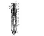
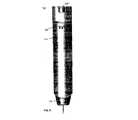
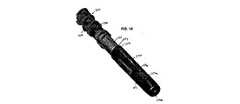
ここで、本発明の自己注射器100について、図1〜59に関してさらに詳細に説明する。自己注射器100は、外側ボディ110と、解除ピン120と、パワーパック130と、カートリッジ容器140と、針カバー150と、医薬品の1回用量を収めるカートリッジ160とを含む。該1回用量は、液体若しくは固体の形態で、又は注射前に混合される液体と固体との組合せとして格納することができる。 The self-
自己注射器100は、図38及び図44〜48に示した外側ボディ110を含む。外側ボディ110は、円筒状のボディに比べてユーザ若しくは介護人が容易に握持/使用できるような、より人間工学的なサイズの概ね卵形又は楕円形である。外側ボディ110の概ね卵形の形状は、自己注射器100が平らな表面から不慮に転がり又は滑り落ちるのを防ぐ。さらに、卵形は、自己注射器100に説明書のラベルを付けるためのより大きな印刷表面を提供する。外側ボディ110が、容易に成型できるように合成材料から形成されることが好ましい。外側ボディ110を通して内部コンポーネントを容易に見ることができるように、外側ボディ110を透明にすることができる。このような構造によって、ユーザは、所定の時点でカートリッジ容器140の窓141a及び141b並びに針カバー150を通してカートリッジ160の内容物を見ることができる。また、外側ボディ110を通して内部コンポーネントが見えないように、外側ボディ110を不透明なものにできることも企図される。また、外側ボディ110が、該外側ボディ110内のコンポーネントを見られるようにする、1つ若しくは複数の窓をもつことも企図される。外側ボディ110には、一端に、解除ピン120を受けるようにサイズ設定された開口部111が形成されている。所定の位置にあるときには、解除ピン120は、自己注射器100の不慮の使用又は始動を防ぐ。解除ピン120は、図32〜34に示されている。操作説明書を外側ボディ110上に直接印刷できることが企図される。また、ラベルを外側ボディ110に貼着できることも企図され、それによって外側ボディ110の剛性を高めることができる。外側ボディ110が1つ若しくは複数の孔部を含むときには、ラベルを設けることで外側ボディ110の強度が高められ、追加の構造補強を設ける必要がなくなる。 Self-
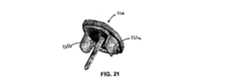
開口部111は、図45、46、及び48に示した、外側ボディ110の対向する側部に沿って下方に延びる側面陥凹部111a及び111bを含む。2つの陥凹部が示されているが、単一の陥凹部を設けることができ、また2つを超える陥凹部を設けることもできることが企図される。陥凹部の数は、タブの数に相当することになる。陥凹部111a及び111bは、解除ピン120上の下方に延びるタブ121a及び121bを受けられるようにサイズ設定される。タブ121a及び121bは、自己注射器100を始動させるために解除ピン120を除去できるようにするには解除ピン120を回転させるのではなく引くべきであることをユーザが容易に認識するように、解除ピン120の回転を妨げる。タブ121a及び121bは、主に、パワーパック130の対向する側部に配置された保持陥凹部235内で受けられる。これについては以下でさらに詳細に説明する。陥凹部111a及び111bは、陥凹部235内のタブ121に接近できるようにしている。タブ121a及び121bは、不慮に除去されるのを防ぐためにパワーパック130上に圧縮嵌合される。ピン120を解放するには、操作者がタブ121を圧迫し、又は締め付けて、タブ121の縁部を陥凹部235から外し、それによってピン120をパワーパック130から引き出す/除去することができる。図に示されるように、タブ121は、陥凹部235の縁部に係合する面取りされた縁部を作り出す曲率を有する。タブ121及び陥凹部235の形状は、完全に相補的であり、それがピン120とパワーパック130との間に摩擦又は圧縮性の保持力を生み出す。解除ピン120は、また、パワーパックの上面で受けられるように適合された、下方に突き出たリブ122a及び122bも含む。リブ122a及び122bは、解除ピン120の安定性及び剛性を増大させる。追加のリブを設けることができることが企図される。解除ピン120は、周辺レッジ124を有する、外側に面する平端部123を含む。周辺レッジ124は、ユーザによる解除ピン120の握持を可能にする。レッジ124は、開口部111に隣接した外側ボディ110の端面上にくるようにサイズ設定される。解除ピン120は、パワーパック130のコレット430に係合する、下方に延びるピン125を含む。ピン125は、所定の位置に固定されたときには(すなわち、解除ピン120の除去前、且つ自己注射器100の作動前)、コレット430の端部が圧迫されるのを防ぎ、それによって自己注射器100の作動を防ぐ。端部123は、外側ボディ110の卵形/楕円形に対応する形状を有する。 The opening 111 includes side recesses 111a and 111b shown in FIGS. 45, 46, and 48 that extend downward along opposite sides of the
図46に示したように、外側ボディ110の内表面は、その中でパワーパック130、カートリッジ容器140、及び針カバー150を受けるように曲線をつけて成形されている。多くの従来技術の針カバーとは異なり、針カバー150は、容器140と外側ボディ110との間に位置決めされ、したがって、ユーザが操作中に該カバー150と接触して、カバーの展開を妨害する、又はカートリッジ内のダイアフラムを過早に破裂させる虞がない。さらに、カバー部材を係止/展開させる機構は、外側ボディ110内に配置され、したがって不正改造及び塵埃の侵入から保護される。外側ボディ110は、開口部111に隣接した外側ボディ110の端部近くの内表面上に形成された、カートリッジ容器保持ステップ112を含む。カートリッジ容器140のレッジ142は、該カートリッジ容器が開口部114から出ていくことがないように、保持ステップ112に当接して、自己注射器100が組み立てられた後の外側ボディ110内のカートリッジ容器140の下方への動きを制限する。複数のパワーパック保持開口部113a、113b、及び113cが、外側ボディ110の少なくとも1つの側部に形成される。パワーパック130上の突起若しくは歯238が、開口部113内にスナップ嵌合される。このスナップ嵌合は、パワーパック130が外側ボディ110内に取り付けられた後で該外側ボディ110から除去されるのを防ぐ。パワーパック外側ボディ230は、外側ボディ110に対して移動可能ではない。カートリッジ容器140のレッジ142は、保持ステップ112とパワーパック130との間に挟まれる。 As shown in FIG. 46, the inner surface of the
開口部114が、開口部111とは反対側の端部で外側ボディ110に形成される。開口部114は、カートリッジ容器140の一部分、針カバー150の一部分がそれらから拡張できるように構成される。ステップ112は、開口部114を通る容器140の移動を制限する。カバー100の末端部分がユーザの注射表面と接触するように、外側ボディ110の端部は、注射表面に隣接するように向けられることを意図されている。 An
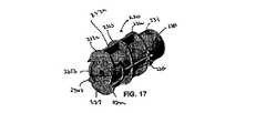
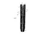
ここで、パワーパック130について、図17〜20、図22〜31、及び図35〜37に関してさらに詳細に説明する。パワーパック130は、パワーパック外側ボディ230と、パワーパック内側ボディ330と、コレット430と、パワーパックばねアセンブリ530とを含む。パワーパックに蓄積されたエネルギーを解放するのに必要な始動力は、4〜8ポンドである。始動力は、自己注射器100が注射表面に押し当てられたときにコレット430を内側ボディ330から解放するために必要な力である。ばねアセンブリ530によってもたらされる注射力は、約30ポンドである。注射力は、カートリッジ160がカートリッジ容器140内を進められて針を駆動し、その結果針がシースを突き抜けてユーザへの医薬品の注射を可能にするように、十分なものでなければならない。パワーパック外側ボディ230は、概ね円筒状の細長い中空ボディ231である。複数の外側周辺リブ232a、232b、及び232cが、中空ボディ231の外表面から外側に延びる。これらのリブ232が示されているが、追加のリブを設けることができることが企図される。リブ232は、自己注射器100の外側ボディ110の変形を防ぐために設けられる。複数の外側長手方向リブ233a、233bが、中空ボディ231の外表面の周りで離隔されている。リブ233は、リブ232と協働して、自己注射器100をさらに補強し、ユーザによって握持されて使用されるときの外側ボディ110の変形を防ぐ。 Here, the
周辺リブの1つ232aは、パワーパック外側ボディ230の上端面237を形成する。解除ピン120の下方に延びるピン125を受けるようにサイズ設定された穴234が、端面に設けられる。保持陥凹部235a及び235bが、中空ボディ231の対向する側部に、上端面に隣接して形成される。陥凹部235a及び235bは、中空ボディ231から外側に、且つ周辺リブ232aの上端面から上方に延びる、壁236a及び236bによって形成される。陥凹部235a及び235bは、解除ピン120が自己注射器100に固定されたときにタブ121a及び121bが陥凹部235a及び235bで受けられるように、外側ボディ110の側面陥凹部111a及び111bと位置合わせされる。陥凹部235a及び235bは、解除ピン120を所定の位置に固定して不慮の除去を防ぐために、タブ121a及び121bに圧迫力を適用するようにサイズ設定される。 One of the peripheral ribs 232 a forms the
図17、26、及び27に示したように、壁236a及び236bは、周辺リブ232aの端面237から上方に延びる。このような配置によって、端面237は、図26に示したように外側ボディ110の端面よりも下方に離隔されて、又は陥凹して、陥凹部115を形成する。陥凹部115は、押しボタンの視覚的効果を低減且つ/又は回避する。したがって、ユーザは、医薬品を投与するために端面237を押そうとはしない。さらに、陥凹部115は、該陥凹部115が自己注射器100の非操作端に位置することをユーザに視覚的に指示しており、その結果、ユーザは、自己注射器の反対側の端部ではなくカバー150を注射器表面に当てて設置しようとする。陥凹部115は、また、ユーザが外側ボディ110上のラベルを読むときに穴234が隠されるように、自己注射器100の端部から穴234を離隔させて、穴234の存在を目立たせないようにする働きもする。したがって、ユーザは、穴234を注射部位に隣接して位置決めしようとはしない。この配置は、自己注射器100の不適切な使用を防止するために提供される一対策にすぎない。解除ピン120のリブ122a及び122bは、陥凹部115内で受けられる。 As shown in FIGS. 17, 26, and 27, the walls 236a and 236b extend upward from the
複数の突起若しくは歯238a、238b、238cが、中空ボディ231の外表面上に形成される。歯238a、238b、238cは、パワーパック130を外側ボディ110内に固定するために、開口部113a、113b、113c内にスナップ嵌合するようにサイズ設定される。この構造によって、他の結合形態の接着剤の必要なしにこれらのコンポーネント110及び130を1つに固定できるようになる。外側ボディ110内の対応する開口部に合致するように、歯238に対応するセットを、中空ボディ230の対向する側部に設けることができる。 A plurality of protrusions or teeth 238a, 238b, 238c are formed on the outer surface of the
中空ボディ231の内部は、保持タブ334をパワーパック内側ボディ330上で受けるようにサイズ設定された陥凹部231aを含む。陥凹部231aは、中空ボディ231の内周の周りを延びる溝とすることができる。陥凹部231aは、端面237とは反対側の端部近くで中空ボディ231に位置決めされる。図1及び28に見られるように、コレット始動構造239が、端面237の内側から中空ボディ231の内部へと延びる。コレット始動構造239は、傾斜したコレット始動表面239aが自由端に配置された、概ね円筒状の形状を有する。ピン120が除去されて注射器の前端が注射部位に押し付けられ、その結果カートリッジ容器140が後方に移動して内側ボディ330に係合するときに、それによってアローヘッド434、特にその後方表面489(図35参照)が後方に押されて表面239aと係合し、コレット430のアローヘッド434を押し合わせてばねアセンブリ530を解放して、医薬品をユーザに注射するのに必要なエネルギーを解放するように、始動表面239aが設けられている。コレット始動構造239を補強するために、リブ239bを設けることができる。コレット430を解放する他の手段を使用できることが企図される。押しボタン型の作動配置を使用することができ、それについては米国特許第4031893号にさらに詳細に記載され、その特許の全体を参照により本願に援用する。 The interior of the
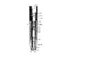
パワーパック内側ボディ330は、概ね円筒状の中空の内側ボディ331である。中空の内側ボディ331は、一端に形成された開口部332を有する。開口部332は、コレットアセンブリ430をパワーパック内側ボディ330内に適切に据え付けることができるように、自己注射器100の組立て時にコレットアセンブリ430の一部分を圧迫するために使用される、コレットアセンブリ導入表面332aを有する。開口部332は、また、始動前にコレット430の対向するアローヘッド434を支持する、反対側の縁部に配置されたコレット保持表面332bを有する。中空の内側ボディ331は、反対側の端部に形成された開口部333を有する。開口部333から離隔されたところに、保持陥凹部231a内にスナップ留めされるようにサイズ設定された複数の保持タブ334がある。陥凹部231及びタブ334は、パワーパック内側ボディ330とパワーパック外側ボディ230との間の限られた動きを可能にする。この配置は、また、自己注射器100を組み立てる目的でも有益である。内側ボディ330及び外側ボディ230は、予め組み立てておくことができる。陥凹部231及びタブ334は、内側ボディ330と外側ボディ230とを、組立てのための適切な位置合わせで支持する。さらに、この配置は、自己注射器100の最終的な組立て前に、内側ボディ330と外側ボディ230とのサブアセンブリが分離するのを防ぐ。また、諸コンポーネントを1つに固定する、外側パワーパックと内側パワーパックとの間の限られた動きを可能にする他の手段を使用できることも企図される。レッジ335が、開口部333の周囲を少なくとも部分的に延びる。レッジ335は、自己注射器100の操作の間の特定の時点でカートリッジ容器140及びパワーパック外側ボディ230に係合するようにサイズ設定され、これについては以下でさらに詳細に説明する。自己注射器100の組立て後、且つ始動前には、内側パワーパック330とカートリッジ容器140との間に間隔が存在して隙間を作り出しており、この隙間が、パワーパック及びばね530に持続的に力がかかるのを回避する。 The power pack
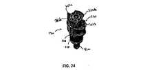
コレット430は、パワーパック内側ボディ330の中空の内部で受けられる。コレット430が、成型された一部品構造であることが好ましい。コレット430は、1対のサイドアーム433a及び433bを形成する開口部432がその中に形成された、細長いボディ431を有する。各サイドアーム433a及び433bは、それぞれアローヘッド細部434a及び434bを含む。各アローヘッド434a及び434bの片側は、コレット保持表面332bに接触且つ係合するように構成される。各アローヘッド434a及び434bの反対側は、コレットアセンブリ導入表面332aに係合するように構成され、それによってサイドアーム433a及び433bを内側にたわませて自己注射器100の操作を可能にすることができる。アローヘッド434a及び434bに隣接したコレット430の端部435は、解除ピン120のピン125を受けるようにサイズ設定された開口部435aを含む。ピン125は、サイドアーム433が互いに向かって内側にたわむのを防ぐ。所定の位置にあるときには、ピン125は、自己注射器100の始動を妨げる。開口部432は、図37に示したように、一端に形成されたアーチ432aを有する。アーチ432aは、サイドアーム433を安定させ、それらサイドアーム433が互いに圧迫されたときに該サイドアームが跳ねて離れるのを助けるのに役立つ。アーチ432aは、コレットに加わる応力の量を低減する。
コレット430は、パワーパックばねアセンブリ530内に位置決めされる。ばねアセンブリ530の一端は、コレット430上に形成されたフランジ436上で支持される。フランジ436は、細長いボディ431から外側に延びる。フランジ436は、ばねアセンブリ530の一端を支持するが、また、ボディ431上のフランジ436の場所も、ユーザに注射される医薬品の1回投与で送達される体積を画定する働きをすることができる。特定の用途では、医薬品の一部分がカートリッジ160内にとどまるように、針を通じて送達される医薬品の量を制御することが望ましい。フランジ436は、液体医薬品の入ったカートリッジ160内をコレット430が移動できる距離を制限することができる。こうして、送達される医薬品の量が制御される。この配置では、フランジ436は、カートリッジ160の端部と接触するようにサイズ設定される。より大きな直径のカートリッジの場合、また医薬品の1回用量がより多い場合、フランジ436をカートリッジ160内で移動できることが企図される。コレット430は、プランジャ438を受ける突起437をさらに含む。プランジャ438は、カートリッジ160内で摺動自在に受けられる。他の用途では、容器160からすべての医薬品を分注することが望ましい。医薬品のわずかな残留量は、針162内、及び針162に隣接したカートリッジ160のネック内に残る。これらの用途では、フランジ436は、カートリッジ160の内部の長さ全体をプランジャ438が移動して針162を通じてすべての医薬品(前述の残留量を除く)を分注するように、カートリッジ160の内部を移動する。様々なサイズのコレット430をこの自己注射器100で使用できることが企図される。したがって、カートリッジのサイズ及び所望の1回用量に基づいて、コレット430を変更することができる。
コレット430が、適切なプラスチック材料から単一部品として形成されることが好ましい。1部品コレット430は、コレットを形成するために必要なコンポーネントの数を削減することによって、製造を単純化し、コストを低減する。従来のコレットでは、多数の真鍮製コンポーネントが使用されることがある。加えて、他の自己注射器では、自己注射器それぞれに異なる量の医薬品に対応するために、コレット430と併せてスペーサを使用する必要があった。本発明によるコレット430は、多コンポーネント構造をなくし、また有利にはスペーサの必要もなくす。コレットの長さは、所望の投与量に基づいて選択することができる。この構造は、さらに、通常プランジャ内に見られる金属インサート、並びにパワーパック内側ボディの上方の射出シート(firing seat)をなくすことができる。様々なサイズのカートリッジ160に対応するように、コレット430自体のサイズ及び形状を多様なものにできることが企図される。フランジ436がカートリッジ160に接触しないときには、針内、又はカートリッジ160のネック内に残っている残留量を除いて、カートリッジ160の内容物全体を分注することが可能である。Wilmotの米国特許第5713866号に開示されているようなニップルプランジャを使用して、カートリッジ160のネック内に医薬品の残留量が蓄積するのを防ぐことができることが企図される。なお、その特許の開示を参照により特に本願に援用する。フランジ436がカートリッジ160と接触する前にコレット及びプランジャ438が該カートリッジ160内をより長い距離移動してより多くの1回用量が分注されるように、該フランジ436が位置決めされるときには、ユーザに注射される投与量を制御するようにフランジ436の位置に変化をつけることができる。コレット430の長さ及びカートリッジ160の直径は、所望の流量が得られるように、カートリッジ160の針162を通る流体の流れを制御するように選択することができる。本発明による自己注射器100は、同一の外側ボディ110及びパワーパック430内で多様なサイズのコレット430を使用できるように構成される。 The
ばねアセンブリ530の反対側の端部は、パワーパック内側ボディ330の内表面に接して、開口部332に当てて置かれる。
ここで、カートリッジ容器140について、図41及び図49〜52に関してさらに詳細に説明する。カートリッジ容器140は、外側ボディ110内で受けられるようにサイズ設定された、概ね細長い中空ボディ141を有する。細長いボディ141の一端にレッジ142が形成される。レッジ142は、外側ボディ110の内表面上に形成された保持ステップ112と接触する。レッジ142は、カートリッジ容器140が開口部114を通って除去されることがないように、外側ボディ110内のカートリッジ容器140の下方への動きを制限する。レッジ142は、パワーパック外側ボディ230上のリブ232a、232b、及び232cと同様に外側に延びる、周辺リブ142a及び142bによって形成される。リブ142a及び142bは、やはり外側ボディ110の変形を防ぐ。The opposite end of the
The
細長い中空ボディ141は、その中でカートリッジ160を受けるようにサイズ設定された中空の内部を有する。中空ボディは、カートリッジ160を中空の内部に配置できるような、またコレット430をカートリッジ160内で摺動自在に受けられるような開口部143を有する。カートリッジ容器140とその係止歯340は、完全な針カバー機能を維持しながら様々なサイズのカートリッジ160を収納するように設計される。したがって、共通設計の針カバーアセンブリ(カートリッジ容器及び係止歯を含める)を、様々な異なる体積の薬物及び異なるサイズの針に使用することができる。より長くより大きなカートリッジの場合、カートリッジ160に損傷を与える又は破損する虞のあるアクスル方向及び径方向の動きを妨げるために、追加の支持材を設けることが望ましい。そのようなアクスル方向及び径方向の動きを妨げるため、カートリッジ160を適切な向きで保持且つ位置合わせするように該カートリッジ160に圧迫力を適用するために、1対のタブ600が中空ボディ141上に形成される。医薬品分注シーケンスの前に、カートリッジが外れる、又はカートリッジホルダ140とともに前方に移動されるのを防ぐために、タブ600は、衝撃負荷時の中空ボディ141内のカートリッジ160の動きを妨げるための摩擦をもたらす。通常、より小さなカートリッジは、タブ600と接触しない。コレット430並びに針及び針シースは、カートリッジを十分に支持する。中空ボディ141の端部は、針162とカートリッジ160の保護シース165とがその中を通過できるようにサイズ設定された開口部144を備える、テーパ構造を有する。テーパ端では、複数のリブ145が中空ボディ141の外表面上に形成される。リブ145は、針カバー150の針カバーばね153を安定させるのに役立つ。リブ145は、また、自己注射器100の組立てを補助するための案内装置の役割も果たす。 The elongated
細長い中空ボディ141には、少なくとも1つの観察窓141a及び141bが形成されている。観察窓141a及び141bは、医薬品が汚染されていない又は期限切れでないことを保証するために、ユーザが自己注射器100の始動前にカートリッジ160の内容物を見られるようにする。 The elongated
図52に示したように、1対の係止アーム若しくはウイング240が、レッジ142から延び、中空ボディ141の中央部分に連結される。各係止ウイング240は、図52に示したように、概ね湾曲形状を有する厚みの大きいストラット241を有する。厚みの大きいストラット241は、係止ウイング240に圧迫荷重が加わるときに(例えば、自己注射器100の使用後にユーザが針カバー150を外側ボディ110内に押し戻そうとするときに)、厚みの大きいストラット241が図52に破線で示された形で曲がるように湾曲している。このような構造によって、係止ウイング240は、カートリッジ容器140のボディ141によって支持され、それによって係止ウイング240の圧迫強度を高めている。好ましくはないが、単一の係止ウイング240を設けることができることが企図される。 As shown in FIG. 52, a pair of locking arms or
より薄いストラット242が、ストラット241の自由端から延び、カートリッジ容器140のボディ141に連結される。ストラット241と242との交点に係止表面243が形成される。係止表面243は、図9及び10に示したように、カバー150上の表面に係合して、自己注射器100操作後のカバー150の内側への移動を制限する。薄い方のストラット242は、ばねの力を与えて、厚い方のストラット241を外方向に付勢された状態に維持する。カバー部材150が拡張位置に移動された後、薄い方のストラット242が針カバー150の案内溝内に保持されたままであるので、この薄い方のストラット242は、また、超高荷重下での引張強度をもたらし、ストラット241が横方向に圧潰するのを防ぐのに役立つ。ストラット242は、その湾曲形状によって、図52に破線で示したように内側に曲がることができる。このことは、ウイング240全体が剛性アーチを形成するのを防ぐ。したがって、ウイング240に沿った過剰な圧迫荷重を引き起こすことなく、厚い方のストラット241をボディ141に向かって内側に曲がらせることができる。係止アーム240を外側ボディ110上に配置できることが企図される。 A
図39、41、49、50、及び52に示したように、カートリッジ容器140の細長いボディ141は、薄い方のストラット242の中間に配置された陥凹部244を含む。係止アーム240が外側ボディ110上に位置する場合、陥凹部244を外側ボディ110に形成することができる。また、別法として、外側ボディ110内に開口部を設けることもできる。この陥凹部244は、薄い方のストラット242がボディ141に向かって内側に移動する距離を増大させており、それによって、厚い方のストラット241を外側に付勢された位置で維持するために該ストラット241に与えられるばねの力を増大させる。係止ウイング240は、通常、応力のかかっていない状態で支持される。係止ウイング240は、針カバー150がそれらの上を通るときに一時的に圧迫される。係止ウイング240は、図10に示したように、係止表面243がカバー部材150に係合するように跳ね出て、針カバー150が後方に押されるのを防ぐ。 As shown in FIGS. 39, 41, 49, 50, and 52, the
細長いボディ141の両側に、細長いスロット146が形成される。スロット146は、図49及び51に示したように、ストラット242の端部から延びる。各スロット146は、係止歯340を受けるようにサイズ設定される。図1、2、4、5、7、9、16、39、及び41に示したように、係止歯340は、カートリッジ容器140の両側に係止される。係止歯340は、自己注射器100の操作後まで針カバー150が展開するのを抑止するために設けられる。1対の係止歯340が設けられている。好ましくはないが、単一の係止歯340を使用できることが企図される。 An
各係止歯340は、アクスルスロット(axle slot)147内で支承スロット(bearing slot)341の周りを回転することができる。歯340の位置を調節できるように、多数のアクスルスロットを設けることができる。図56〜59に示したように、各係止歯340は、支承表面(bearing surface)342aをもつタブ342を有する。タブ342は、細長いボディ141の内部に延びてカートリッジ160に接触できるように、スロット146内に位置決めされる。自己注射器100の操作の間にカートリッジ160がボディ141内を進められるにつれて、カートリッジ160と支承表面342aとの接触が、係止歯340をアクスル341の周りで回転させる。表面342aがカートリッジ160と接触しているが、係止歯340は、注射操作の間、容器140内のカートリッジ160の動きに最小限又は無視できるほどの影響しか与えない。係止歯からカートリッジに加わる力が小さい又は最小限であることは、針が完全に拡張される前にダイアフラムを過早に破裂させる虞のあるカートリッジ内の圧力上昇を起こさないという点で有利である。さらに、容器140内のカートリッジ160の動きは、係止歯340によって妨害されない、又は無視できるほどしか妨害されない。タブ342は、アクスル341の片側から延びる。スプリングテール(spring tail)343が、アクスル341の反対側から延びる。スプリングテール343は、スロット146内に位置決めされ、カートリッジ容器140に沿って摺動するように設計される。スプリングテール343は、自己注射器100の操作前に針カバー150が格納位置で保持又は係止されるように、係止歯340を係止位置へと付勢する働きをする。スプリングテール343をばねアセンブリで置き換えられることが企図される。スプリングテール343がスロット146内でカートリッジ容器140に沿って滑らかに摺動できるように、支承表面344がテール343の一端に設けられている。支承表面344及び中心ボディ345は、突出しピンのための平らな領域を提供する。 Each locking
スプリングテール343の下方に、V字形ノッチ347が形成される。ノッチ347は、片側に、自己注射器100の始動前に針カバー150を保持する係止表面347aを有する。もう1つの表面347bは、カートリッジ容器140内での歯340の移動を制限して、その回転を制限する。ノッチ347は、スプリングテール343の両側を延びるタブ348の一部として形成される。係止歯340は、自己注射器100のフレキシビリティを高める。自己注射器100を修正することなく様々な長さ及び直径の多数のカートリッジを使用することができる。テール343のばねの作用は、表面342aがカートリッジ160と接触するように係止歯340の位置を調節する。 A V-shaped
カートリッジ容器140は、ボディ141の両側に形成された1対の開口部141a及び141bをさらに含む。開口部141a及び141bは、ユーザが自己注射器100の操作前に医薬品を目視検査できるよう、カートリッジ160の内容物を見えるようにする。使用前、開口部141a及び141bは、ユーザが外側ボディ110を通してカートリッジ160の内容物を見られるように、カバー部材150の対応する開口部と位置合わせされる。複数の補強リブ149aを有するレッジ149が、開口部141の一端に隣接して形成される。レッジ149は、針カバー150が外側ボディ110から引き出されることがないように、カバー部材150の開口部154の縁部154aと接触して、針カバー150がカートリッジ容器140に対してそれ以上前方に移動するのを防ぐ。この位置にあるときには、係止ウイング240の係止表面243が針カバー150の端部に係合して、針カバー150が外側ボディ110内に戻されるのを防ぐ。レッジ149が針カバー150の開口部の縁部と接触しているときには、カートリッジ容器及び針カバーの開口部は、もはや位置合わせされておらず、したがってユーザは、外側ボディ110を通してカートリッジ160を見ることができない。これによって、自己注射器100が使用されたことをユーザに案内する視覚的指示を提供する。 The
ここで、針カバー150について、図12〜15、38、42、43、及び53〜54に関してさらに詳細に説明する。針カバー150は、外側ボディ110の形状に相補的な形状の、概ね細長い中空ボディ151を有する。細長いボディ151は、外側ボディ100内で摺動自在に受けられる。中空ボディ151の一端は、先細になり、閉囲された端面152を有する。端面152は、図7及び8に示したように、注射操作の間にカートリッジ160の針がその中を通過できるようにサイズ設定された開口部152aを有する。端面152は、自己注射器100の操作の間、ユーザの注射表面上に置かれることを意図されている。図1、2、4、5、7、及び9に示したように、針カバーばね153が、針カバー150の端面152とカートリッジ容器140との間で圧縮される。本発明による針カバー150を備えた自己注射器100は、自己注射器を操作するために同様の始動力が必要となる点で、針カバーのない自己注射器と同様に機能するように設計される。したがって、ばね153は、負荷が非常に低い。カバー150のための付勢力は、自己注射器100の始動力よりも小さい。ばね153の最大負荷が1.5ポンドであることが好ましい。負荷は、’893号特許に開示されているようなカバーのない注射器に比べて針カバー150が自己注射器100の操作に影響を与えないように、自己注射器100を始動させるのに必要な始動力よりも低い(4〜8に対して1.5)。カートリッジ容器140上のリブ145は、カバー150内でばね153を安定させる役割を果たす。中空ボディ151には、図53及び54に示したインデント151aを含めることができる。インデント151aは、プラスチックの厚さを縮小して材料を節約する。 The
中空ボディ151は、その上に形成された1対の開口部154をさらに含む。前述のように、開口部154は、カートリッジ160内の医薬品を視認可能にするために、始動前にカートリッジ容器140の開口部141a及び141は位置合わせされる。開口部154の縁部の表面154aは、レッジ149に接触して針カバー150のそれ以上の前進を妨げるように設計される。 The
針カバー150の両側にスロット155が設けられる。スロット155は、係止ウイング240及び係止歯340と位置合わせされるように位置決めされる。スロット155は、針カバー150の展開前、係止ウイング240を案内且つ支持する。係止歯340を針カバー150内のスロット155を通じてカートリッジ容器140上の所定の位置に挿入できるように、自己注射器100の組立てを補助するための十字形スロット155aを設けることができる。スロット155aを通じて支承表面344を設置することができる。係止突起156が、スロット155内へと内側に延びる。係止突起156は、係止歯340上の係止表面347aに係合するように構成される。支承スロット341のためのカートリッジ容器140内の多数のアクスルスロット147に対応するように、多数の突起156が設けられる。
中空ボディ151の内部に、内部溝157が設けられる。内部溝157は、スロット155とアクスル方向に位置合わせされる。カバー部材150が図12及び13に示した位置にあるときには、ストラット241の一部分が溝157内に位置合わせされる。溝は、係止ウイング240と位置合わせされて、該係止ウイング240を支持し、該係止ウイング240の横方向の圧潰を防ぐ。 An
カートリッジ160は、プランジャ438及びコレット430を受けるようにサイズ設定された開口部161をその一端に有する、概ね細長いガラス管を含む。針162を通じて分注される投与量を制御するために、コレット430上のフランジ436は、カートリッジ160の端部と接触して、プランジャ及びコレットがカートリッジ160内へと内側に移動するのを制限するように設計される。針162は、カートリッジ160の他端に固定されたハブアセンブリ163に取り付けられる。ハブアセンブリ163には、自己注射器の始動前に液体医薬品が針162内を通過するのを防ぐために、ダイアフラム164を含めることができる。針162は、保護シース165内に収められる。シース165は、ハブアセンブリ163に固定される。操作中、針162が針カバー150を通って突き出るときに、針162は、シース165を突き抜ける。カートリッジ160は、ここに示したように、1回用量の液体医薬品のための容器を提供する。自己注射器100を単一の液体の使用だけに制限しようとするものではなく、むしろ、自己注射器100始動時に混合される1つ若しくは複数の液体をカートリッジ160内に格納できることが企図される。さらに、固体医薬品と液体とをカートリッジ160内に別々に格納し、それによって分注前に固体が液体に溶解されるようにすることもできる。
ここで、自己注射器100の操作について、さらに詳細に説明する。自己注射器100は、図1、2、及び3に、非始動状態で示されている。解除ピン120は、サイドアーム433が内側にたわむことがないように、ピン125が穴234及びコレット430の穴435a内で受けられるような所定の位置に固定される。この位置では、針カバー150は、係止歯340によって、係止された格納位置で保持される。係止表面347aは、スプリングテール343によって付勢されて、針カバー部材150上の係止突起と位置合わせされている。この位置では、自己注射器100を操作することができず、針162は、露出されていない。 Here, the operation of the self-
自己注射器100の操作が望まれるときには、解除ピン120が周辺レッジ124で握持され、引き出されて、自己注射器100の端部から解除ピン120が除去される。これで、自己注射器100が、図4に示したように操作の準備ができた状態になる。この時点で、アローヘッド434a及び434b並びにサイドアーム433a及び433bを、自己注射器100が始動されたときに共に圧迫することができる。このとき、係止ウイング240は、圧迫されておらず、また応力も受けていない。 When operation of the self-
図5及び6に示したように、ユーザは、針カバー150の端面152を注射部位に押し当てる。このことが、予め圧縮されたばね153をさらにわずかに圧縮させ、ついには針カバー150が移動してカートリッジ容器140の前端145aに接触し(図51参照)、それによってカートリッジ容器140のレッジ142を後方に移動させる。ばね153の力は、ばね530の力よりも小さい。次いで、針カバー150、カートリッジ容器140、及びカートリッジ160が、外側ボディ110内へと後方に移動される。カートリッジ容器140は、それらのレッジ142がパワーパック内側ボディ330のレッジ335に接触するまで、外側ボディ110内へと上方に移動する。次いで、パワーパック内側ボディ330、並びにコレット430及びばねアセンブリ530が自己注射器100内へと後方に押され、パワーパック外側ボディ230内に到達する。コレット430は、上方に移動して、ついには図28に示したコレット始動構造239と接触する。アローヘッド434a及び434bは、傾斜した始動表面239aと接触する。コレット430が後方に移動するにつれてアローヘッド434a及び434bが傾斜表面239によって共に圧迫され、その結果、該アローヘッド434a及び434bがコレット保持表面332bから解放される。この負荷操作の間に、カバー部材150は、外側ボディ110内へと少し後方に押される。これが起こると、ばね153によって係止歯340に与えられていた予荷重が一時的に除去される。したがって、V字形のノッチ347は、針カバー150上に形成された突起156との係合から一時的に外れる。この操作の間、突起156は、もはや表面347a若しくは347bのいずれにも接触していないが、それらの表面間にもたらされた空間にはとどまる。したがって、カバー部材150からの圧力が除去されると、突起156は、表面347a若しくは347bと接触した状態に戻る。係止歯340は、カートリッジ140がカートリッジ容器160内を前方に移動するときの該カートリッジ140の動きに応答した場合に限り、カバー部材150を完全に解放する。したがって、カバー部材150は、カートリッジ140が移動して初めて展開することができる。 As shown in FIGS. 5 and 6, the user presses the end surface 152 of the
ばね530及びコレット430は、同時にカートリッジ160及びカートリッジ容器140を外側ボディ110の開口した前端に向かって前方に押し進める。針162が針カバー150を通って拡張したら、カートリッジ160内の医薬品の圧力がダイアフラム164を破裂させて、医薬品をユーザへと流入させる。薬物が針162内を押し進められて、プランジャ438及びコレット430をさらにカートリッジ160内へと移動させる。カートリッジ容器140は、シース165を保持し、またさらに、ばね530のばねの力がカートリッジ140を通じて針カバー150及び注射部位上に伝わるのを防ぐ。すなわち、カートリッジ160を前方に駆動するばね530からの力は、針カバー150によって直接受けられるのではなく、それらの間でシース165が圧迫された状態で、カートリッジ容器140の前端によって妨害される。加えて、針カバーのばねの力は、始動時にコレットを解放するために該コレットを圧潰するのに必要な始動力よりも小さい。針カバーばねの力が、最小始動力の約0.25〜0.75であることが好ましい。始動後のパワーパック残留ばね力は、カートリッジ容器140、カートリッジ160、外側ボディ110、及びパワーパック外側ボディ230内に含まれる。この配置は、有利には、キックバック効果が起こるのを都合良く防ぐ。したがって、始動中に自己注射器が注射部位から押しのけられず、その結果、確実に医薬品の適切な1回用量が投与され、針の適切な拡張長さ又は適切な針の貫入が維持される。この効果は、ばね530からのばねの力が針カバー150及び注射部位へと伝わり、それによって自己注射器100が注射部位から押しのけられ、注射部位内の針162の場所を変化させる虞がある場合に生じる。このことには、患者を驚かせることや、その注射を筋肉内注射から皮下注射へと変化させてpkレベルに影響を及ぼすことを含めた、いくつかの悪影響がある。同時に、カートリッジ160は、カートリッジ容器140内を進められる(すなわち、そのときに針160が格納位置から拡張位置へと移行する)。カートリッジ160が進むと、係止歯340をアクスル341の周りで回転させることになる。これは、カートリッジ160が支承表面342aに接触して、該支承表面342aを針162の主要長手アクスルから押し離すことに応答したものである。係止歯340のこの回転は、係止表面347aを係止突起156との係合から外れさせる。表面347bは、係止歯340の回転を制限する。この時点で、カバー部材150は、該カバー部材がカートリッジ容器140に対して移動できるような、非係止位置にある。コレット430をコレット保持表面332bから解放すると、パワーパック内側ボディ330の端部がパワーパック外側ボディ230と接触させられる。 The
1回用量がユーザに注射されたら、ユーザは、自己注射器100を注射表面から取り除く。針カバー150がカートリッジ容器140に対して係止されていないので、ばね153は、図9及び11に示したように、針カバー150を外側ボディ110から押し出して、露出した針162を覆わせる。スロット155が溝157と位置合わせされ、且つストラット241の一部分がスロット157内で保持されているので、カバー150が外側に移動するときには、ストラット241のその一部分は、溝157内に移動する。針カバー160が外側に摺動するとき、厚い方のストラット241が溝157内を摺動するにつれて、係止ウイング240は、針カバー160によって一時的に圧迫される。この圧迫は、溝157の底面がストラット241の上面と接触するときに起こる。ウイング240は、図52に破線で示した形で圧迫される。厚い方のストラット241が溝157を通り抜けて、ウイング240及び針カバー150が図10、14、及び15に示した位置にくると、係止表面243は、針カバー150の端部に接触して、針カバーが外側ボディ110内に再び挿入されるのを防ぐ。万一内向きの力が加わった場合、表面243が針カバー150と係合したままになるように、ストラット241及び242は、係止ウイング240がカートリッジ容器140のボディ141に押し当てられるように圧迫される。この配置は、針カバー160の内側への移動を制限する。レッジ149は、針カバー150の開口部154の縁部154aに係合する。このとき、自己注射器100は、操作不可能な保管位置にある。 Once a single dose has been injected by the user, the user removes the self-
本発明を以上の諸実施態様及び諸実施例に関して開示してきたが、これで、当業者には他の変形態様が明らかであろう。本発明の範囲から逸脱することなく、前述の自己注射器に様々な修正及び変更を実施することができる。本発明は、具体的に言及した実施態様だけに制限されるものではなく、したがって、独占権が主張される本発明の趣旨及び範囲を評価するには、以上の好ましい諸実施態様及び諸実施例の議論ではなく、冒頭の特許請求の範囲を参照すべきである。 While the present invention has been disclosed in terms of the above embodiments and examples, other variations will now be apparent to those skilled in the art. Various modifications and changes can be made to the self-injector described above without departing from the scope of the invention. The present invention is not limited to the specifically mentioned embodiments, and thus the preferred embodiments and examples described above can be used to evaluate the spirit and scope of the present invention where exclusive rights are claimed. Reference should be made to the appended claims rather than to the following discussion.
以下の諸図によって、本発明の様々な実施態様の理解が得られる。これら様々な図の類似要素は、共通の参照番号を有する。
Claims (141)
Translated fromJapaneseハウジングと;
前記ハウジング内に配置されたカートリッジ容器と;
前記カートリッジ容器内で受けられたカートリッジであって、その中に少なくとも1つの開口部を有し、及び後方をプランジャによって密閉された医薬品を含み、それを通じて前記医薬品を分注するための針アセンブリを含む、前記カートリッジと;
蓄積エネルギー源を提供する作動アセンブリであって、前記蓄積エネルギー源が開放されて前記カートリッジ内で前記プランジャを駆動し、前記針アセンブリを通じて前記医薬品を分注することができる、前期作動アセンブリと;
前記ハウジング内で受けられた針カバーであって、医薬品分注操作の間に針アセンブリがその中を通過できるようにサイズ設定され形成された開口部と、前記自己注射器の始動前に前記針カバーを係止された格納位置に置く第1の係止位置と、前記自己注射器の操作後に前記針カバーを係止された拡張位置に置く第2の係止位置とを有する、前記針カバーと;
前記針カバーを前記第1の係止位置で保持する第1の係止アセンブリと;
前記針カバーを前記第2の係止位置で保持する第2の係止アセンブリとを含む、前記自己注射器。Self-injector:
A housing;
A cartridge container disposed within the housing;
A cartridge received within the cartridge container, comprising a medicament having at least one opening therein and sealed rearward by a plunger, through which a needle assembly for dispensing the medicament is provided. Including the cartridge;
An actuating assembly for providing a stored energy source, wherein the stored energy source is opened to drive the plunger within the cartridge to dispense the medicament through the needle assembly;
A needle cover received within the housing, the opening being sized and configured to allow a needle assembly to pass therethrough during a pharmaceutical dispensing operation, and the needle cover prior to activation of the self-injector; The needle cover having a first locking position that places the needle cover in a locked retracted position and a second locking position that places the needle cover in a locked extended position after operation of the self-injector;
A first locking assembly for holding the needle cover in the first locking position;
And a second locking assembly for holding the needle cover in the second locking position.
このとき作動アセンブリが前記蓄積エネルギー源を解放するために必要な始動力を有し、かつ前記針カバーばねアセンブリが付勢力を提供し、
前記始動力が前記付勢力よりも大きい、請求項1記載の自己注射器。A needle cover spring assembly for moving the needle cover from the locked retracted position to the locked extended position;
The actuating assembly then has the necessary starting force to release the stored energy source, and the needle cover spring assembly provides the biasing force;
The self-injector according to claim 1, wherein the starting force is greater than the biasing force.
外側ボディと;
前記外側ボディに動作可能に結合された内側ボディと;
前記内側ボディに動作可能に結合されたコレットと;
エネルギー源とを含む、請求項1記載の自己注射器。The actuating assembly is:
With the outer body;
An inner body operably coupled to the outer body;
A collet operably coupled to the inner body;
The self-injector according to claim 1, comprising an energy source.
ハウジングと;
前記ハウジング内に配置されたカートリッジ容器と;
前記カートリッジ容器内で受けられたカートリッジであって、その中に少なくとも1つの開口部を有し、かつ後方をプランジャによって密閉された医薬品と、それを通じて前記医薬品を分注するための針アセンブリとを含む、前記カートリッジ;
蓄積エネルギー源を提供する作動アセンブリであって、前記蓄積エネルギー源が開放されて前記カートリッジ内で前記プランジャを駆動し、前記針アセンブリを通じて前記医薬品を分注することができる、前期作動アセンブリと;
前記ハウジング内で少なくとも部分的に受けられた針カバーであって、医薬品分注操作の間に針アセンブリがその中を通過できるようにサイズ設定され形成された開口部と、第1の係止された格納位置と第2の係止された拡張位置とを有する、前記針カバーと;
前前記カバー部材を前記第1の係止位置及び前記第2の係止位置で選択的に保持する係止機構であって、前記カバー部材及び前記ハウジングの少なくとも一方によって外部接触から保護されるように構築且つ配置される、前記係止機構とを含む、前記自己注射器。Self-injector:
A housing;
A cartridge container disposed within the housing;
A cartridge received in the cartridge container, the drug product having at least one opening therein and sealed rearward by a plunger; and a needle assembly for dispensing the drug product therethrough Containing the cartridge;
An actuating assembly for providing a stored energy source, wherein the stored energy source is opened to drive the plunger within the cartridge to dispense the medicament through the needle assembly;
A needle cover received at least partially within the housing, the opening being sized and formed to allow a needle assembly to pass therethrough during a pharmaceutical dispensing operation, and a first locked; The needle cover having a closed storage position and a second locked extended position;
A locking mechanism that selectively holds the front cover member at the first locking position and the second locking position, and is protected from external contact by at least one of the cover member and the housing. The self-injector comprising the locking mechanism constructed and arranged in
前記針カバーを前記第1の係止位置で保持する第1の係止アセンブリと;
前記針カバーを前記第2の係止位置で保持する第2の係止アセンブリとを含む、請求項71記載の自己注射器。The locking mechanism is:
A first locking assembly for holding the needle cover in the first locking position;
72. The self-injector of claim 71, comprising a second locking assembly that holds the needle cover in the second locked position.
このとき作動アセンブリが前記蓄積エネルギー源を解放するために必要な始動力を有し、かつ前記針カバーばねアセンブリが付勢力を提供し、
前記始動力が前記付勢力よりも大きい、請求項70記載の自己注射器。A needle cover spring assembly for moving the needle cover from the locked retracted position to the locked extended position;
The actuating assembly then has the necessary starting force to release the stored energy source, and the needle cover spring assembly provides the biasing force;
71. The self-injector according to claim 70, wherein the starting force is greater than the biasing force.
外側ボディと;
前記外側ボディに動作可能に結合された内側ボディと;
前記内側ボディに動作可能に結合されたコレットと;
エネルギー源とを含む、請求項70記載の自己注射器。The actuating assembly is:
With the outer body;
An inner body operably coupled to the outer body;
A collet operably coupled to the inner body;
71. The self-injector of claim 70, comprising an energy source.
Applications Claiming Priority (4)
| Application Number | Priority Date | Filing Date | Title |
|---|---|---|---|
| US59905404P | 2004-08-06 | 2004-08-06 | |
| US60/599,054 | 2004-08-06 | ||
| US11/095,664 | 2005-04-01 | ||
| US11/095,664US7449012B2 (en) | 2004-08-06 | 2005-04-01 | Automatic injector |
Related Parent Applications (1)
| Application Number | Title | Priority Date | Filing Date |
|---|---|---|---|
| JP2007525030ADivisionJP4362143B2 (en) | 2004-08-06 | 2005-08-04 | Automatic syringe |
Publications (2)
| Publication Number | Publication Date |
|---|---|
| JP2009090140Atrue JP2009090140A (en) | 2009-04-30 |
| JP4806712B2 JP4806712B2 (en) | 2011-11-02 |
Family
ID=35758362
Family Applications (2)
| Application Number | Title | Priority Date | Filing Date |
|---|---|---|---|
| JP2007525030AExpired - LifetimeJP4362143B2 (en) | 2004-08-06 | 2005-08-04 | Automatic syringe |
| JP2009017421AExpired - LifetimeJP4806712B2 (en) | 2004-08-06 | 2009-01-29 | Automatic syringe |
Family Applications Before (1)
| Application Number | Title | Priority Date | Filing Date |
|---|---|---|---|
| JP2007525030AExpired - LifetimeJP4362143B2 (en) | 2004-08-06 | 2005-08-04 | Automatic syringe |
Country Status (19)
| Country | Link |
|---|---|
| US (7) | US7449012B2 (en) |
| EP (3) | EP2204201B1 (en) |
| JP (2) | JP4362143B2 (en) |
| KR (1) | KR20070083539A (en) |
| CN (1) | CN101166551A (en) |
| AU (2) | AU2005271355C1 (en) |
| CA (1) | CA2576776A1 (en) |
| CY (3) | CY1115201T1 (en) |
| DK (3) | DK1786491T3 (en) |
| ES (3) | ES2792185T3 (en) |
| HU (2) | HUE028698T2 (en) |
| IL (2) | IL181118A (en) |
| MX (1) | MX2007001298A (en) |
| PL (3) | PL1786491T3 (en) |
| PT (2) | PT2311510E (en) |
| SG (1) | SG139748A1 (en) |
| SI (3) | SI1786491T1 (en) |
| TW (1) | TWI407981B (en) |
| WO (1) | WO2006017732A2 (en) |
Cited By (2)
| Publication number | Priority date | Publication date | Assignee | Title |
|---|---|---|---|---|
| KR20170016875A (en)* | 2014-06-04 | 2017-02-14 | 타이세이카코 카부시키가이샤 | Syringe cap, needle-mounted syringe, and prefilled syringe formulation |
| JP2021524781A (en)* | 2018-05-24 | 2021-09-16 | ノバルティス アーゲー | Automatic drug delivery device |
Families Citing this family (235)
| Publication number | Priority date | Publication date | Assignee | Title |
|---|---|---|---|---|
| US6428528B2 (en) | 1998-08-11 | 2002-08-06 | Antares Pharma, Inc. | Needle assisted jet injector |
| US7544188B2 (en)* | 2001-07-19 | 2009-06-09 | Intelliject, Inc. | Medical injector |
| WO2003068290A2 (en) | 2002-02-11 | 2003-08-21 | Antares Pharma, Inc. | Intradermal injector |
| US9486581B2 (en)* | 2002-09-11 | 2016-11-08 | Becton, Dickinson And Company | Injector device with force lock-out and injection rate limiting mechanisms |
| US7220244B2 (en)* | 2003-08-04 | 2007-05-22 | Bioquiddity, Inc. | Infusion apparatus with constant force spring energy source |
| IL157981A (en) | 2003-09-17 | 2014-01-30 | Elcam Medical Agricultural Cooperative Ass Ltd | Auto-injector |
| GB2414403B (en)* | 2004-05-28 | 2009-01-07 | Cilag Ag Int | Injection device |
| GB2414406B (en)* | 2004-05-28 | 2009-03-18 | Cilag Ag Int | Injection device |
| GB2414402B (en) | 2004-05-28 | 2009-04-22 | Cilag Ag Int | Injection device |
| GB2414399B (en)* | 2004-05-28 | 2008-12-31 | Cilag Ag Int | Injection device |
| GB2414775B (en)* | 2004-05-28 | 2008-05-21 | Cilag Ag Int | Releasable coupling and injection device |
| GB2414409B (en)* | 2004-05-28 | 2009-11-18 | Cilag Ag Int | Injection device |
| GB2414400B (en)* | 2004-05-28 | 2009-01-14 | Cilag Ag Int | Injection device |
| GB2414401B (en)* | 2004-05-28 | 2009-06-17 | Cilag Ag Int | Injection device |
| GB0414054D0 (en) | 2004-06-23 | 2004-07-28 | Owen Mumford Ltd | Improvements relating to automatic injection devices |
| US20230127062A1 (en)* | 2004-08-06 | 2023-04-27 | Mylan Specialty L.P. | Automatic injector with needle cover |
| US7449012B2 (en)* | 2004-08-06 | 2008-11-11 | Meridian Medical Technologies, Inc. | Automatic injector |
| US8048035B2 (en)* | 2004-08-06 | 2011-11-01 | Meridian Medical Technologies, Inc. | Automatic injector with needle cover |
| US10737028B2 (en) | 2004-11-22 | 2020-08-11 | Kaleo, Inc. | Devices, systems and methods for medicament delivery |
| US7947017B2 (en)* | 2004-11-22 | 2011-05-24 | Intelliject, Inc. | Devices, systems and methods for medicament delivery |
| US7648483B2 (en)* | 2004-11-22 | 2010-01-19 | Intelliject, Inc. | Devices, systems and methods for medicament delivery |
| WO2006057636A1 (en) | 2004-11-22 | 2006-06-01 | Intelliject, Llc | Devices, systems, and methods for medicament delivery |
| US11590286B2 (en) | 2004-11-22 | 2023-02-28 | Kaleo, Inc. | Devices, systems and methods for medicament delivery |
| US7648482B2 (en) | 2004-11-22 | 2010-01-19 | Intelliject, Inc. | Devices, systems, and methods for medicament delivery |
| HUE042286T2 (en) | 2005-01-24 | 2019-06-28 | Antares Pharma Inc | Needle-filled pre-filled syringe |
| US8231573B2 (en) | 2005-02-01 | 2012-07-31 | Intelliject, Inc. | Medicament delivery device having an electronic circuit system |
| US9022980B2 (en) | 2005-02-01 | 2015-05-05 | Kaleo, Inc. | Medical injector simulation device |
| US7731686B2 (en) | 2005-02-01 | 2010-06-08 | Intelliject, Inc. | Devices, systems and methods for medicament delivery |
| AU2006210865B2 (en) | 2005-02-01 | 2008-12-04 | Kaleo, Inc. | Devices, systems, and methods for medicament delivery |
| US8361026B2 (en)* | 2005-02-01 | 2013-01-29 | Intelliject, Inc. | Apparatus and methods for self-administration of vaccines and other medicaments |
| US8206360B2 (en) | 2005-02-01 | 2012-06-26 | Intelliject, Inc. | Devices, systems and methods for medicament delivery |
| US7850664B1 (en)* | 2005-03-01 | 2010-12-14 | Pruter Rick L | Method and system for protecting and using biopsy system instruments |
| GB2424837B (en)* | 2005-04-06 | 2010-10-06 | Cilag Ag Int | Injection device |
| GB2425062B (en)* | 2005-04-06 | 2010-07-21 | Cilag Ag Int | Injection device |
| GB2424838B (en)* | 2005-04-06 | 2011-02-23 | Cilag Ag Int | Injection device (adaptable drive) |
| GB2424836B (en) | 2005-04-06 | 2010-09-22 | Cilag Ag Int | Injection device (bayonet cap removal) |
| GB2424835B (en) | 2005-04-06 | 2010-06-09 | Cilag Ag Int | Injection device (modified trigger) |
| GB2427826B (en) | 2005-04-06 | 2010-08-25 | Cilag Ag Int | Injection device comprising a locking mechanism associated with integrally formed biasing means |
| PL1759729T3 (en)* | 2005-08-30 | 2010-09-30 | Cilag Gmbh Int | Needle assembly for a prefilled syringe system |
| US20110098656A1 (en)* | 2005-09-27 | 2011-04-28 | Burnell Rosie L | Auto-injection device with needle protecting cap having outer and inner sleeves |
| GB0601309D0 (en) | 2006-01-23 | 2006-03-01 | Medical House The Plc | Injection device |
| US20070173770A1 (en) | 2006-01-23 | 2007-07-26 | The Medical House Plc | Injection device |
| EP2139545B1 (en)* | 2006-03-14 | 2013-06-05 | Ricardo Sheath Oxford Steyn | Protective device for a needle assembly |
| US7993304B2 (en)* | 2006-03-15 | 2011-08-09 | Bioquiddity, Inc. | Fluid dispensing apparatus |
| US7828772B2 (en)* | 2006-03-15 | 2010-11-09 | Bioquiddity, Inc. | Fluid dispensing device |
| WO2007126851A2 (en)* | 2006-03-29 | 2007-11-08 | Intelliject, Llc | Devices, systems and methods for medicament delivery |
| FR2899482A1 (en)* | 2006-04-11 | 2007-10-12 | Becton Dickinson France Soc Pa | Automatic medicament/product injection device for patient, has safety shield coupled to housing, and provided in active state at end of needle insertion step before which product/medicament injection step is not started |
| WO2007131013A1 (en) | 2006-05-03 | 2007-11-15 | Antares Pharma, Inc. | Two-stage reconstituting injector |
| WO2007131025A1 (en) | 2006-05-03 | 2007-11-15 | Antares Pharma, Inc. | Injector with adjustable dosing |
| GB2438593B (en) | 2006-06-01 | 2011-03-30 | Cilag Gmbh Int | Injection device (cap removal feature) |
| GB2438591B (en)† | 2006-06-01 | 2011-07-13 | Cilag Gmbh Int | Injection device |
| GB2438590B (en)* | 2006-06-01 | 2011-02-09 | Cilag Gmbh Int | Injection device |
| KR101396797B1 (en) | 2006-06-30 | 2014-05-26 | 애브비 바이오테크놀로지 리미티드 | Automatic injection device |
| EP2125075A2 (en) | 2007-01-22 | 2009-12-02 | Intelliject, Inc. | Medical injector with compliance tracking and monitoring |
| US7833195B2 (en)* | 2007-03-14 | 2010-11-16 | Bioquiddity, Inc. | Fluid dispensing apparatus |
| US8211059B2 (en)* | 2007-06-25 | 2012-07-03 | Kriesel Marshall S | Fluid dispenser with additive sub-system |
| US20080319385A1 (en)* | 2007-06-25 | 2008-12-25 | Kriesel Marshall S | Fluid dispenser with additive sub-system |
| EP3636301A1 (en) | 2008-03-10 | 2020-04-15 | Antares Pharma, Inc. | Injector safety device |
| US8021344B2 (en) | 2008-07-28 | 2011-09-20 | Intelliject, Inc. | Medicament delivery device configured to produce an audible output |
| USD994111S1 (en) | 2008-05-12 | 2023-08-01 | Kaleo, Inc. | Medicament delivery device cover |
| US8052645B2 (en) | 2008-07-23 | 2011-11-08 | Avant Medical Corp. | System and method for an injection using a syringe needle |
| US8177749B2 (en) | 2008-05-20 | 2012-05-15 | Avant Medical Corp. | Cassette for a hidden injection needle |
| CA3070618C (en) | 2008-05-20 | 2021-07-20 | Avant Medical Corp. | Autoinjector system |
| GB2461086B (en)* | 2008-06-19 | 2012-12-05 | Cilag Gmbh Int | Injection device |
| GB2461089B (en) | 2008-06-19 | 2012-09-19 | Cilag Gmbh Int | Injection device |
| GB2461085B (en)* | 2008-06-19 | 2012-08-29 | Cilag Gmbh Int | Injection device |
| GB2461087B (en)* | 2008-06-19 | 2012-09-26 | Cilag Gmbh Int | Injection device |
| GB2461088B (en)* | 2008-06-19 | 2012-09-26 | Cilag Gmbh Int | Injection device |
| GB2461084B (en)* | 2008-06-19 | 2012-09-26 | Cilag Gmbh Int | Fluid transfer assembly |
| US8376993B2 (en) | 2008-08-05 | 2013-02-19 | Antares Pharma, Inc. | Multiple dosage injector |
| DE102008037310B4 (en) | 2008-08-11 | 2023-11-16 | Ypsomed Ag | Automatic injection device for administering a fixed dose |
| US12097357B2 (en) | 2008-09-15 | 2024-09-24 | West Pharma. Services IL, Ltd. | Stabilized pen injector |
| GB0821492D0 (en)* | 2008-11-25 | 2008-12-31 | Team Holdings Uk Ltd | Integrated auto-injector cartridge system |
| GB0823693D0 (en) | 2008-12-31 | 2009-02-04 | Owen Mumford Ltd | Autoinjector |
| GB0900930D0 (en)* | 2009-01-20 | 2009-03-04 | Future Injection Technologies Ltd | Injection device |
| GB0901801D0 (en) | 2009-02-05 | 2009-03-11 | Medical House Plc The | Improved autoinjector |
| JP5732039B2 (en) | 2009-03-20 | 2015-06-10 | アンタレス・ファーマ・インコーポレーテッド | Hazardous drug injection system |
| WO2010127146A1 (en)* | 2009-04-29 | 2010-11-04 | Abbott Biotechnology Ltd | Automatic injection device |
| GB0907534D0 (en) | 2009-05-01 | 2009-06-10 | Owen Mumford Ltd | Injection devices |
| USD621929S1 (en)* | 2009-05-28 | 2010-08-17 | F. Hoffmann-La Roche Ag | Auto-injector |
| USD623738S1 (en)* | 2009-05-28 | 2010-09-14 | F. Hoffman La-Roche AG | Auto-injector |
| US20110015576A1 (en)* | 2009-06-01 | 2011-01-20 | Sanofi-Aventis Deutschland Gmbh | Medicament identification system for multi-dose injection devices |
| EP2440270B1 (en) | 2009-06-12 | 2013-04-24 | Novo Nordisk A/S | Drug delivery device with cap functions for needle assembly |
| US10350364B2 (en) | 2009-11-11 | 2019-07-16 | Windgap Medical, Inc. | Portable Drug Mixing and Delivery Device and Associated Methods |
| CN102711867B (en) | 2009-12-04 | 2014-10-08 | 贝克顿·迪金森公司 | Self-injection device with multi-position cap |
| EP2512558A4 (en)* | 2009-12-15 | 2014-08-13 | Abbvie Biotechnology Ltd | IMPROVED TRIP PUSHER FOR AUTOMATIC INJECTION DEVICE |
| DK2536453T3 (en)* | 2010-02-18 | 2014-11-24 | Sanofi Aventis Deutschland | autoinjector |
| EP3338833B1 (en) | 2010-02-18 | 2020-07-29 | Sanofi-Aventis Deutschland GmbH | Auto-injector with a torsion spring |
| USD644733S1 (en)* | 2010-02-22 | 2011-09-06 | Becton, Dickinson And Company | Needle hub |
| USD638539S1 (en)* | 2010-02-22 | 2011-05-24 | Becton, Dickinson And Company | Needle hub |
| NZ702172A (en) | 2010-04-21 | 2016-03-31 | Abbvie Biotechnology Ltd | Wearable automatic injection device for controlled delivery of therapeutic agents |
| WO2011163511A1 (en)* | 2010-06-23 | 2011-12-29 | Tcb Medical Devices, Llc | Injector for auto-injection of medication and associated method of use |
| WO2012022810A2 (en) | 2010-08-19 | 2012-02-23 | Novo Nordisk A/S | Medical injection device |
| TWI459986B (en) | 2010-11-08 | 2014-11-11 | Shl Group Ab | Container holder assembly |
| GB201020475D0 (en)* | 2010-12-02 | 2011-01-19 | Oval Medical Technologies Ltd | Delivery mechanism for an autoinjector |
| GB201020472D0 (en)* | 2010-12-02 | 2011-01-19 | Oval Medical Technologies Ltd | A drive assembly for an autoinjector |
| US20130281934A1 (en) | 2010-12-30 | 2013-10-24 | Meridian Medical Technologies, Inc. | Slip-Resistant Autoinjectors |
| JP2014503307A (en) | 2010-12-30 | 2014-02-13 | メリディアン メディカル テクノロジーズ インコーポレイテッド | Automatic syringe with three chambers |
| KR101989342B1 (en) | 2011-01-24 | 2019-06-14 | 애브비 바이오테크놀로지 리미티드 | Removal of needle shields from syringes and automatic injection devices |
| BR112013018905B1 (en) | 2011-01-24 | 2021-07-13 | Abbvie Biotechnology Ltd | AUTOMATIC INJECTION DEVICES THAT HAVE OVERMOLDED HANDLE SURFACES. |
| ES2710905T3 (en) | 2011-01-24 | 2019-04-29 | E3D Agricultural Coop Association Ltd | Injector |
| US9173999B2 (en) | 2011-01-26 | 2015-11-03 | Kaleo, Inc. | Devices and methods for delivering medicaments from a multi-chamber container |
| US8939943B2 (en) | 2011-01-26 | 2015-01-27 | Kaleo, Inc. | Medicament delivery device for administration of opioid antagonists including formulations for naloxone |
| US8627816B2 (en) | 2011-02-28 | 2014-01-14 | Intelliject, Inc. | Medicament delivery device for administration of opioid antagonists including formulations for naloxone |
| PL2699293T3 (en) | 2011-04-20 | 2019-08-30 | Amgen Inc. | Autoinjector apparatus |
| US20140042741A1 (en)* | 2011-04-28 | 2014-02-13 | Ilona Eggert | Dispense interface with lockout element |
| US9220660B2 (en) | 2011-07-15 | 2015-12-29 | Antares Pharma, Inc. | Liquid-transfer adapter beveled spike |
| US8496619B2 (en) | 2011-07-15 | 2013-07-30 | Antares Pharma, Inc. | Injection device with cammed ram assembly |
| BR112014005465A2 (en) | 2011-09-09 | 2017-03-21 | Merck Patent Gmbh | autoinjector with separate needle injection |
| US9486583B2 (en) | 2012-03-06 | 2016-11-08 | Antares Pharma, Inc. | Prefilled syringe with breakaway force feature |
| EP4186545A1 (en) | 2012-04-06 | 2023-05-31 | Antares Pharma, Inc. | Needle assisted jet injection administration of testosterone compositions |
| DK3284493T3 (en)* | 2012-04-13 | 2020-11-02 | Becton Dickinson Co | Micro-infusion device with automatic needle retraction |
| USD808010S1 (en) | 2012-04-20 | 2018-01-16 | Amgen Inc. | Injection device |
| USD898908S1 (en) | 2012-04-20 | 2020-10-13 | Amgen Inc. | Pharmaceutical product cassette for an injection device |
| US9364610B2 (en) | 2012-05-07 | 2016-06-14 | Antares Pharma, Inc. | Injection device with cammed ram assembly |
| US9522235B2 (en) | 2012-05-22 | 2016-12-20 | Kaleo, Inc. | Devices and methods for delivering medicaments from a multi-chamber container |
| CN104394909B (en)* | 2012-05-25 | 2017-03-29 | 阿普塔尔法国简易股份公司 | Automatic injector |
| WO2013178511A1 (en)* | 2012-05-29 | 2013-12-05 | Carebay Europe Ltd | Medicament container retaining mechanism |
| US9114216B2 (en) | 2012-07-16 | 2015-08-25 | Accunit, Llc | Handheld medical substance dispensing system, apparatus and methods |
| US9724479B2 (en) | 2012-07-16 | 2017-08-08 | Accunit, Llc | Handheld medical substance dispensing system, apparatus and methods |
| WO2014037946A1 (en) | 2012-09-05 | 2014-03-13 | Elcam Medical Agricultural Cooperative Association Ltd. | Electronic auto-injection device |
| CN104768593B (en)* | 2012-10-03 | 2017-08-15 | 卡贝欧洲有限公司 | drug delivery device |
| KR101767793B1 (en)* | 2012-10-11 | 2017-08-11 | 케어베이 유럽 리미티드 | Automatic injection training device |
| US9643770B2 (en) | 2012-12-03 | 2017-05-09 | Mylan Inc. | System and method for medicament storage, dispensing, and administration |
| US9692829B2 (en) | 2012-12-03 | 2017-06-27 | Mylan Inc. | Medication delivery system and method |
| US20140155827A1 (en) | 2012-12-03 | 2014-06-05 | Mylan, Inc. | Medicament information system and method |
| US9179260B2 (en) | 2012-12-03 | 2015-11-03 | Mylan Inc. | Medicament information system and method |
| BR112015014658A2 (en)* | 2012-12-21 | 2017-07-11 | Carebay Europe Ltd | medicine release device |
| GB2526948A (en) | 2012-12-27 | 2015-12-09 | Kaleo Inc | Systems for locating and interacting with medicament delivery devices |
| FI3659647T3 (en) | 2013-02-11 | 2024-03-28 | Antares Pharma Inc | NEEDLE-ASSISTED SPRAY INJECTOR WITH REDUCED TRIGGER FORCE |
| US8591463B1 (en) | 2013-03-08 | 2013-11-26 | Teva Pharmaceutical Industries Ltd. | Re-useable injector device for syringe |
| US8652100B1 (en) | 2013-03-08 | 2014-02-18 | Teva Pharmaceutical Industries, Ltd. | Re-useable injector device for syringe |
| CA2905031C (en) | 2013-03-11 | 2018-01-23 | Hans PFLAUMER | Dosage injector with pinion system |
| WO2014165136A1 (en) | 2013-03-12 | 2014-10-09 | Antares Pharma, Inc. | Constant volume prefilled syringes and kits thereof |
| EP2777684A1 (en) | 2013-03-14 | 2014-09-17 | Sanofi-Aventis Deutschland GmbH | Medicament container carrier and adapter |
| US10569017B2 (en) | 2013-03-15 | 2020-02-25 | Windgap Medical, Inc. | Portable drug mixing and delivery device and associated methods |
| US11246842B2 (en) | 2014-12-18 | 2022-02-15 | Windgap Medical, Inc. | Method and compositions for dissolving or solubilizing therapeutic agents |
| ES2973257T3 (en) | 2013-03-15 | 2024-06-19 | Amgen Inc | Drug cassette, autoinjector and autoinjector system |
| US9907910B2 (en) | 2013-03-15 | 2018-03-06 | Windgap Medical, Inc. | Portable drug mixing and delivery device and associated methods |
| CA2904661C (en) | 2013-03-15 | 2022-03-15 | Amgen Inc. | Drug cassette, autoinjector, and autoinjector system |
| US10391262B2 (en) | 2014-03-18 | 2019-08-27 | Windgap Medical, Inc. | Removable actuating cap for use with an auto-injector assembly |
| WO2017062005A1 (en)* | 2015-10-08 | 2017-04-13 | Windgap Medical | Portable drug mixing and delivery device and associated methods |
| JP6560187B2 (en) | 2013-03-15 | 2019-08-14 | ウインドギャップ メディカル インコーポレイテッド | Portable drug mixing and delivery system and method |
| US12239822B2 (en) | 2013-03-15 | 2025-03-04 | Windgap Medical, Inc. | Portable drug mixing and delivery device and associated methods |
| GB2515032A (en) | 2013-06-11 | 2014-12-17 | Cilag Gmbh Int | Guide for an injection device |
| GB2517896B (en) | 2013-06-11 | 2015-07-08 | Cilag Gmbh Int | Injection device |
| GB2515039B (en) | 2013-06-11 | 2015-05-27 | Cilag Gmbh Int | Injection Device |
| GB2515038A (en) | 2013-06-11 | 2014-12-17 | Cilag Gmbh Int | Injection device |
| GB201313782D0 (en) | 2013-08-01 | 2013-09-18 | Oval Medical Technologies Ltd | Drug delivery device |
| PL234202B1 (en)* | 2013-09-30 | 2020-01-31 | Htl Strefa Spolka Akcyjna | Safety needle device |
| ES2978587T3 (en) | 2013-10-07 | 2024-09-16 | Antares Pharma Inc | Hematocrit modulation by needle-assisted jet injection of testosterone |
| CN105722539B (en) | 2013-11-13 | 2021-01-15 | 豪夫迈·罗氏有限公司 | Auxiliary manual injection device and method |
| USD745664S1 (en) | 2013-11-25 | 2015-12-15 | Teva Pharmaceutical Industries, Ltd. | Injector device for a syringe |
| AU2014364433A1 (en) | 2013-12-18 | 2016-08-04 | Windgap Medical, Inc. | Drug mixing and delivery system and method |
| WO2015118550A2 (en) | 2014-02-10 | 2015-08-13 | Elcam Medical Agricultural Cooperative Association Ltd. | Semi disposable auto injector |
| USD760891S1 (en) | 2014-02-12 | 2016-07-05 | Abbvie Inc. | Injection tool |
| US10398839B2 (en) | 2014-02-14 | 2019-09-03 | Shl Medical Ag | Automatic injection device |
| EP3107547A4 (en) | 2014-02-19 | 2017-11-15 | Antares Pharma, Inc. | Needle assisted jet injection administration of testosterone compositions |
| JP6629231B2 (en) | 2014-04-04 | 2020-01-15 | ノボ・ノルデイスク・エー/エス | Automatic injection device with needle shield trigger |
| JP6302573B2 (en)* | 2014-06-16 | 2018-03-28 | クック・メディカル・テクノロジーズ・リミテッド・ライアビリティ・カンパニーCook Medical Technologies Llc | Plunger-driven collet handle and fiducial deployment system |
| CN106456907A (en) | 2014-06-27 | 2017-02-22 | 诺和诺德股份有限公司 | Autoinjector having needle shield triggering |
| US9517307B2 (en) | 2014-07-18 | 2016-12-13 | Kaleo, Inc. | Devices and methods for delivering opioid antagonists including formulations for naloxone |
| CA2994803C (en) | 2014-08-18 | 2023-09-12 | Windgap Medical, Inc. | Portable drug mixing and delivery device and associated methods |
| US11116903B2 (en) | 2014-08-18 | 2021-09-14 | Windgap Medical, Inc | Compression seal for use with a liquid component storage vial of an auto-injector |
| US10799634B2 (en)* | 2014-11-12 | 2020-10-13 | Novo Nordisk A/S | Method of manufacturing one of a range of autoinjectors |
| US9784685B2 (en)* | 2014-12-10 | 2017-10-10 | Molecular Devices, Inc. | Liquid and plate sensors for microplate injector system |
| US9415176B1 (en) | 2015-01-22 | 2016-08-16 | West Pharmaceutical Services, Inc. | Autoinjector having an end-of-dose visual indicator |
| US10737027B2 (en)* | 2015-01-27 | 2020-08-11 | Shl Medical Ag | Medicament delivery device |
| KR101525854B1 (en)* | 2015-02-06 | 2015-06-11 | (주)엠큐어 | Portable Auto Inejector |
| CN107530502B (en) | 2015-02-20 | 2021-01-15 | 里珍纳龙药品有限公司 | Syringe system, piston sealing system, stopper system |
| US10695495B2 (en) | 2015-03-24 | 2020-06-30 | Kaleo, Inc. | Devices and methods for delivering a lyophilized medicament |
| GB2537638A (en)* | 2015-04-21 | 2016-10-26 | Consort Medical Plc | Medicament delivery device |
| US10758677B2 (en)* | 2015-04-24 | 2020-09-01 | Shl Medical Ag | Drive mechanism |
| CN113181477B (en) | 2015-06-04 | 2023-07-14 | 麦迪麦珀医疗工程有限公司 | Cartridge insertion for drug delivery device |
| CA2990950A1 (en) | 2015-06-30 | 2017-01-05 | Kaleo, Inc. | Auto-injectors for administration of a medicament within a prefilled syringe |
| WO2017009284A1 (en) | 2015-07-10 | 2017-01-19 | Alk-Abelló A/S | An injector comprising a safety pin |
| DK3325051T3 (en)* | 2015-07-23 | 2019-10-21 | Shl Medical Ag | VARIABLE SINGLE DOSAGE INJECTOR |
| CA2994300C (en) | 2015-08-13 | 2023-12-05 | Windgap Medical, Inc. | Mixing and injection device with sterility features |
| US10850036B2 (en) | 2015-08-27 | 2020-12-01 | E3D Agricultural Cooperative Association | Reusable automatic injection device |
| CN108495679B (en)* | 2015-11-27 | 2021-05-25 | 赛诺菲-安万特德国有限公司 | drug injection device |
| JP7069014B2 (en) | 2015-11-27 | 2022-05-17 | サノフィ-アベンティス・ドイチュラント・ゲゼルシャフト・ミット・ベシュレンクテル・ハフツング | Injection device |
| US11260176B2 (en) | 2015-12-30 | 2022-03-01 | Novo Nordisk A/S | Autoinjector having needle shield triggering |
| CA2960260A1 (en)* | 2016-03-11 | 2017-09-11 | Arta Plast Ab | Safety injection needle device |
| US10532157B2 (en) | 2016-04-08 | 2020-01-14 | University Of Washington | Ampule autoinjector systems and methods |
| USD819198S1 (en) | 2016-04-28 | 2018-05-29 | Amgen Inc. | Autoinjector with removable cap |
| DK3452143T3 (en)* | 2016-05-06 | 2020-09-07 | Sanofi Aventis Deutschland | INJECTOR FACILITY |
| WO2017210011A1 (en)* | 2016-05-30 | 2017-12-07 | Blue Lead Medical Llc | Autoinjector and user wearable autoinjector assembly |
| WO2018061948A1 (en)* | 2016-09-30 | 2018-04-05 | テルモ株式会社 | Cap, syringe assembly, and prefilled syringe |
| WO2018119218A1 (en) | 2016-12-23 | 2018-06-28 | Kaleo, Inc. | Medicament delivery device and methods for delivering drugs to infants and children |
| CA3046354A1 (en) | 2017-01-17 | 2018-07-26 | Kaleo, Inc. | Medicament delivery devices with wireless connectivity and event detection |
| NZ767760A (en)* | 2017-01-20 | 2025-07-25 | L G P Tech Holdings Llc | Auto-injector device |
| WO2018154452A1 (en) | 2017-02-24 | 2018-08-30 | Wockhardt Limited | Autoinjector with a needle cover |
| GB2560524B (en)* | 2017-03-13 | 2019-07-31 | Univ Cape Town | An auto-injector |
| WO2018195764A1 (en)* | 2017-04-25 | 2018-11-01 | 群康生技股份有限公司 | Injection pen |
| WO2018218167A1 (en) | 2017-05-25 | 2018-11-29 | West Pharmaceutical Services, Inc. | Smart syringe using nfc communication and capacitance detection |
| KR20240055848A (en) | 2017-06-30 | 2024-04-29 | 리제너론 파아마슈티컬스, 인크. | Auto-injector with anti-roll features |
| US10888693B2 (en) | 2017-08-22 | 2021-01-12 | Warsaw Orthopedic, Inc. | Drug pellet injector needle and method |
| WO2019043502A1 (en) | 2017-09-04 | 2019-03-07 | Wockhardt Limited | Autoinjector with a needle cover |
| CA3079354C (en)* | 2017-10-16 | 2022-08-30 | Becton, Dickinson And Company | Sterilization arrangement for drug delivery device |
| JP1629334S (en) | 2017-10-25 | 2019-04-15 | ||
| JP7402799B2 (en)* | 2017-12-22 | 2023-12-21 | ウェスト ファーマ サービシーズ イスラエル リミテッド | Syringes available with different cartridge sizes |
| US20210121631A1 (en)* | 2018-01-19 | 2021-04-29 | Birya Biotech, Inc. | Tool for servicing an auto-injector |
| US10357619B1 (en) | 2018-02-08 | 2019-07-23 | Chalbourne Brasington | Auto-injection device |
| WO2019182745A1 (en) | 2018-03-19 | 2019-09-26 | Bryn Pharma, LLC | Epinephrine spray formulations |
| US11083712B1 (en) | 2018-03-20 | 2021-08-10 | Relevale, Inc. | Low concentration delivery of an ergoline derivative for treatment of a headache |
| EP3801694B1 (en) | 2018-06-08 | 2025-08-27 | Antares Pharma, Inc. | Auto-insert injector |
| USD932006S1 (en) | 2018-11-21 | 2021-09-28 | Regeneron Pharmaceuticals, Inc. | Auto-injector cap |
| USD903856S1 (en) | 2018-06-29 | 2020-12-01 | Regeneron Pharmaceuticals, Inc. | Auto-injector |
| US11929160B2 (en) | 2018-07-16 | 2024-03-12 | Kaleo, Inc. | Medicament delivery devices with wireless connectivity and compliance detection |
| JP7520284B2 (en) | 2018-09-04 | 2024-07-23 | アラジェ,インコーポレイテッド | Injector |
| CA3145580A1 (en) | 2019-08-09 | 2021-02-18 | Kaleo, Inc. | Devices and methods for delivery of substances within a prefilled syringe |
| CN114466670B (en)* | 2019-09-09 | 2024-08-02 | 西医药服务有限公司 | Tracking and locking mechanism for injection device |
| USD1010811S1 (en) | 2019-09-30 | 2024-01-09 | Amgen Inc. | Handheld drug delivery device |
| FR3103708B1 (en)* | 2019-12-02 | 2021-12-03 | Aptar France Sas | Fluid product injection device |
| US20220378610A1 (en)* | 2019-12-03 | 2022-12-01 | University Of Florida Research Foundation, Inc. | Devices and methods for intravitreal injection of substances |
| USD1030041S1 (en) | 2020-01-14 | 2024-06-04 | Amgen Inc. | Handheld drug delivery device |
| USD1030040S1 (en) | 2020-01-14 | 2024-06-04 | Amgen Inc. | Handheld drug delivery device |
| US11235105B2 (en)* | 2020-03-20 | 2022-02-01 | Alexander Nikon | Auto-injector |
| WO2021211412A1 (en)* | 2020-04-14 | 2021-10-21 | West Pharmaceutical Services, Inc. | Injection device with passive safety mechanism |
| CN111658896B (en)* | 2020-06-18 | 2020-12-15 | 普昂(杭州)医疗科技有限公司 | An automatic trigger needle protection device and an insulin pen needle |
| US10898655B1 (en) | 2020-07-30 | 2021-01-26 | Benson Eric Wengreen | Auto-injectors featuring medicine delivery assurance |
| EP4228721A1 (en)* | 2020-10-14 | 2023-08-23 | SHL Medical AG | Medicament delivery member guard lock assembly |
| USD973866S1 (en) | 2020-11-05 | 2022-12-27 | Amgen Inc. | Handheld drug delivery device |
| USD974547S1 (en) | 2020-11-05 | 2023-01-03 | Amgen Inc. | Handheld drug delivery device |
| USD962423S1 (en) | 2020-11-05 | 2022-08-30 | Amgen Inc. | Handheld drug delivery device |
| TW202233586A (en)* | 2020-11-10 | 2022-09-01 | 美商麥迪貝肯有限公司 | Subcutaneous and intramuscular administration of pyrazine compounds |
| TW202237207A (en) | 2020-12-31 | 2022-10-01 | 美商再生元醫藥公司 | Auto-injector and related methods of use |
| US12268847B1 (en) | 2021-02-10 | 2025-04-08 | Kaleo, Inc. | Devices and methods for delivery of substances within a medicament container |
| USD985116S1 (en) | 2021-03-10 | 2023-05-02 | Amgen Inc. | Handheld drug delivery device |
| USD985117S1 (en) | 2021-03-10 | 2023-05-02 | Amgen Inc. | Handheld drug delivery device |
| USD985118S1 (en) | 2021-03-10 | 2023-05-02 | Amgen Inc. | Handheld drug delivery device |
| USD985119S1 (en) | 2021-03-30 | 2023-05-02 | Amgen Inc. | Handheld drug delivery device |
| EP4323038A1 (en)* | 2021-04-14 | 2024-02-21 | West Pharmaceutical Services, Inc. | Safety shield for an injection device |
| MX2023015403A (en)* | 2021-06-17 | 2024-02-20 | Amgen Inc | Drug delivery device having shock absorber. |
| CN119947766A (en)* | 2022-07-07 | 2025-05-06 | 伊玛拉公司 | Wearable system for breast pumping utilizing massage |
Citations (2)
| Publication number | Priority date | Publication date | Assignee | Title |
|---|---|---|---|---|
| JPH10113388A (en)* | 1996-08-23 | 1998-05-06 | Becton Dickinson Fr Sa | Injection device |
| JP2002508225A (en)* | 1997-12-16 | 2002-03-19 | メリディアン メディカル テクノロジーズ,インコーポレイテッド | Automatic syringe |
Family Cites Families (56)
| Publication number | Priority date | Publication date | Assignee | Title |
|---|---|---|---|---|
| US2866458A (en)* | 1956-05-09 | 1958-12-30 | Becton Dickinson Co | Hypodermic assembly |
| US3712301A (en) | 1971-01-11 | 1973-01-23 | Survival Technology | Gun type hypodermic injector with rapid cartridge displacement within holder |
| US3882863A (en)* | 1973-08-01 | 1975-05-13 | Survival Technology | Hypodermic injection device having cannula covered with resilient sheath |
| US4031893A (en) | 1976-05-14 | 1977-06-28 | Survival Technology, Inc. | Hypodermic injection device having means for varying the medicament capacity thereof |
| US4226235A (en) | 1979-01-25 | 1980-10-07 | Survival Technology, Inc. | Plural injecting device |
| US4329988A (en) | 1980-12-23 | 1982-05-18 | Survival Technology, Inc. | Plural injection assembly |
| US4394863A (en) | 1981-10-23 | 1983-07-26 | Survival Technology, Inc. | Automatic injector with cartridge having separate sequentially injectable medicaments |
| US4723937A (en) | 1985-05-20 | 1988-02-09 | Survival Technology, Inc. | Plural dosage automatic injector with a by-pass fitment |
| US5026349A (en)* | 1988-10-05 | 1991-06-25 | Autoject Systems Inc. | Liquid medicament injector system |
| US5282793A (en)* | 1989-10-02 | 1994-02-01 | Larson Eldon E | Syringe holder and applicator |
| WO1991011212A1 (en) | 1990-02-02 | 1991-08-08 | Gerard Philip Gilliland | A retractable sharp |
| US5271744A (en) | 1991-04-29 | 1993-12-21 | George C. Kramer | System and method for rapid vascular drug delivery |
| US5405362A (en)* | 1991-04-29 | 1995-04-11 | The Board Of Regents For The University Of Texas System | Interactive external defibrillation and drug injection system |
| GB9200219D0 (en) | 1992-01-07 | 1992-02-26 | Medimech Int Ltd | Automatic injectors |
| EP0693946B1 (en)* | 1993-03-24 | 2001-05-16 | Owen Mumford Limited | Improvements relating to injection devices |
| US5478316A (en)* | 1994-02-02 | 1995-12-26 | Becton, Dickinson And Company | Automatic self-injection device |
| GB9412301D0 (en)* | 1994-06-17 | 1994-08-10 | Safe T Ltd | Hollow-needle drugs etc applicators |
| CA2154853C (en) | 1994-07-27 | 2007-01-16 | John Glyndwr Wilmot | Nipple plunger |
| US5658259A (en) | 1995-10-19 | 1997-08-19 | Meridian Medical Technologies, Inc. | Dental cartridge assembly auto-injector with protective needle cover |
| US5776107A (en)* | 1996-12-31 | 1998-07-07 | Delab | Injection device |
| CA2586178A1 (en) | 1997-12-16 | 1999-06-24 | Meridian Medical Technologies, Inc. | Automatic injector for administrating a medicament |
| DE29801168U1 (en) | 1998-01-24 | 1999-08-12 | Medico Dev Investment Co | Injection device |
| DE19822031C2 (en)* | 1998-05-15 | 2000-03-23 | Disetronic Licensing Ag | Auto injection device |
| DE19821933C1 (en) | 1998-05-15 | 1999-11-11 | Disetronic Licensing Ag | Device for administering an injectable product |
| US6428528B2 (en) | 1998-08-11 | 2002-08-06 | Antares Pharma, Inc. | Needle assisted jet injector |
| SE9803662D0 (en)* | 1998-10-26 | 1998-10-26 | Pharmacia & Upjohn Ab | autoinjector |
| FR2794650B1 (en)* | 1999-06-10 | 2001-09-14 | Marc Brunel | SINGLE USE INJECTION DEVICE |
| US6391003B1 (en) | 1999-10-25 | 2002-05-21 | Antares Pharma, Inc. | Locking mechanism for a jet injector |
| CA2382459C (en)* | 1999-11-29 | 2009-12-29 | Mdc Investment Holdings, Inc. | Combination safety needle assembly and medical apparatus |
| US6689092B2 (en)* | 2000-03-03 | 2004-02-10 | Boehringer International Gmbh | Needle-less injector of miniature type |
| DE60106685T2 (en)* | 2000-07-18 | 2005-12-01 | Ventradex Ag | safety syringe |
| US6641561B1 (en)* | 2000-10-10 | 2003-11-04 | Meridian Medical Technologies, Inc. | Drug delivery device |
| SE518981C2 (en) | 2000-12-14 | 2002-12-17 | Shl Medical Ab | autoinjector |
| CN1262315C (en)* | 2001-04-13 | 2006-07-05 | 佩恩椰特公司 | Modular gas-pressured needled-less injector |
| WO2002094356A1 (en) | 2001-05-22 | 2002-11-28 | Elan Pharma International Limited | Mechanism for prevention of premature activation, in particular in drug administration |
| GB0118419D0 (en)* | 2001-07-28 | 2001-09-19 | Owen Mumford Ltd | Improvements relating to injection devices |
| US7569035B1 (en) | 2001-11-02 | 2009-08-04 | Meridian Medical Technologies, Inc. | Automatic injector with anti-coring needle |
| US20030105430A1 (en)* | 2001-11-30 | 2003-06-05 | Elan Pharma International Limited Wil House | Automatic injector |
| KR20040096561A (en) | 2002-02-15 | 2004-11-16 | 앤태어스 파머, 인코퍼레이티드 | Injector with bypass channel |
| US6976976B2 (en)* | 2002-03-27 | 2005-12-20 | Safety Syringes, Inc. | Syringe with needle guard injection device |
| US6979316B1 (en)* | 2002-05-23 | 2005-12-27 | Seedlings Life Science Ventures Llc | Apparatus and method for rapid auto-injection of medication |
| JP4448448B2 (en)* | 2002-09-24 | 2010-04-07 | エス・ホー・エル・グループ・アクチボラゲット | Injection device |
| AU2003275893B2 (en)* | 2002-11-25 | 2008-11-13 | Tecpharma Licensing Ag | Device for automatically injecting an active agent |
| US6846302B2 (en) | 2002-12-31 | 2005-01-25 | Teva Medical Ltd. | Needle protector device |
| US6767336B1 (en) | 2003-01-09 | 2004-07-27 | Sheldon Kaplan | Automatic injector |
| US6805686B1 (en)* | 2003-05-06 | 2004-10-19 | Abbott Laboratories | Autoinjector with extendable needle protector shroud |
| GB0312852D0 (en)* | 2003-06-05 | 2003-07-09 | Owen Mumford Ltd | Improvements relating to syringe firing mechanisms |
| US7500963B2 (en)* | 2003-07-22 | 2009-03-10 | Safety Syringes, Inc. | Systems and methods for automatic medical injection with safeguard |
| DE10351598A1 (en)* | 2003-11-05 | 2005-06-16 | Tecpharma Licensing Ag | Auto-injection device |
| GB2409445B (en) | 2003-12-22 | 2006-03-29 | Eurocut Ltd | Labelling system |
| GB2410188B (en) | 2004-01-23 | 2006-01-25 | Medical House Plc | Injection device |
| US20050222539A1 (en) | 2004-03-30 | 2005-10-06 | Pediamed Pharmaceuticals, Inc. | Automatic injection device |
| EP3470099A1 (en) | 2004-04-29 | 2019-04-17 | AbbVie Inc. | Autoinjector with extendable needle protector shroud |
| AU2013222015A1 (en)* | 2004-08-06 | 2013-09-19 | Meridian Medical Technologies, Inc. | Automatic injector |
| US7449012B2 (en) | 2004-08-06 | 2008-11-11 | Meridian Medical Technologies, Inc. | Automatic injector |
| US20120101475A1 (en) | 2010-10-21 | 2012-04-26 | Meridian Medical Technologies, Inc. | High Efficiency Auto-Injector |
- 2005
- 2005-04-01USUS11/095,664patent/US7449012B2/ennot_activeExpired - Lifetime
- 2005-08-04SISI200532042Tpatent/SI1786491T1/enunknown
- 2005-08-04HUHUE05783727Apatent/HUE028698T2/enunknown
- 2005-08-04SISI200532278Tpatent/SI2204201T1/enunknown
- 2005-08-04PTPT101944148Tpatent/PT2311510E/enunknown
- 2005-08-04HUHUE10155967Apatent/HUE049358T2/enunknown
- 2005-08-04AUAU2005271355Apatent/AU2005271355C1/ennot_activeExpired
- 2005-08-04DKDK05783727.0Tpatent/DK1786491T3/enactive
- 2005-08-04CNCNA2005800342900Apatent/CN101166551A/enactivePending
- 2005-08-04EPEP10155967.2Apatent/EP2204201B1/ennot_activeRevoked
- 2005-08-04PLPL05783727Tpatent/PL1786491T3/enunknown
- 2005-08-04DKDK10155967.2Tpatent/DK2204201T3/enactive
- 2005-08-04MXMX2007001298Apatent/MX2007001298A/ennot_activeApplication Discontinuation
- 2005-08-04JPJP2007525030Apatent/JP4362143B2/ennot_activeExpired - Lifetime
- 2005-08-04PLPL10194414Tpatent/PL2311510T3/enunknown
- 2005-08-04CACA002576776Apatent/CA2576776A1/ennot_activeAbandoned
- 2005-08-04ESES10155967Tpatent/ES2792185T3/ennot_activeExpired - Lifetime
- 2005-08-04ESES10194414.8Tpatent/ES2481366T3/ennot_activeExpired - Lifetime
- 2005-08-04SISI200531856Tpatent/SI2311510T1/enunknown
- 2005-08-04KRKR1020077005210Apatent/KR20070083539A/ennot_activeWithdrawn
- 2005-08-04EPEP10194414.8Apatent/EP2311510B1/ennot_activeRevoked
- 2005-08-04EPEP05783727.0Apatent/EP1786491B1/ennot_activeRevoked
- 2005-08-04DKDK10194414.8Tpatent/DK2311510T3/enactive
- 2005-08-04PLPL10155967Tpatent/PL2204201T3/enunknown
- 2005-08-04SGSG200800394-9Apatent/SG139748A1/enunknown
- 2005-08-04WOPCT/US2005/027889patent/WO2006017732A2/enactiveApplication Filing
- 2005-08-04ESES05783727.0Tpatent/ES2564236T3/ennot_activeExpired - Lifetime
- 2005-08-04PTPT101559672Tpatent/PT2204201T/enunknown
- 2005-08-08TWTW094126864Apatent/TWI407981B/ennot_activeIP Right Cessation
- 2007
- 2007-02-01ILIL181118Apatent/IL181118A/enactiveIP Right Grant
- 2007-10-25USUS11/923,729patent/US7794432B2/ennot_activeExpired - Lifetime
- 2009
- 2009-01-29JPJP2009017421Apatent/JP4806712B2/ennot_activeExpired - Lifetime
- 2010
- 2010-02-11ILIL203925Apatent/IL203925A0/enactiveIP Right Grant
- 2010-04-27AUAU2010201665Apatent/AU2010201665C1/ennot_activeExpired
- 2010-08-17USUS12/857,641patent/US8870827B2/enactiveActive
- 2014
- 2014-06-26CYCY20141100468Tpatent/CY1115201T1/enunknown
- 2014-09-22USUS14/492,234patent/US20150011944A1/ennot_activeAbandoned
- 2016
- 2016-03-02CYCY20161100183Tpatent/CY1117383T1/enunknown
- 2017
- 2017-03-06USUS15/450,247patent/US20170173271A1/ennot_activeAbandoned
- 2019
- 2019-07-26USUS16/522,897patent/US20190381255A1/enactiveGranted
- 2020
- 2020-05-21CYCY20201100465Tpatent/CY1122922T1/enunknown
- 2022
- 2022-09-16USUS17/946,674patent/US20230017559A1/ennot_activeAbandoned
Patent Citations (2)
| Publication number | Priority date | Publication date | Assignee | Title |
|---|---|---|---|---|
| JPH10113388A (en)* | 1996-08-23 | 1998-05-06 | Becton Dickinson Fr Sa | Injection device |
| JP2002508225A (en)* | 1997-12-16 | 2002-03-19 | メリディアン メディカル テクノロジーズ,インコーポレイテッド | Automatic syringe |
Cited By (8)
| Publication number | Priority date | Publication date | Assignee | Title |
|---|---|---|---|---|
| KR20170016875A (en)* | 2014-06-04 | 2017-02-14 | 타이세이카코 카부시키가이샤 | Syringe cap, needle-mounted syringe, and prefilled syringe formulation |
| KR102549755B1 (en)* | 2014-06-04 | 2023-06-29 | 타이세이카코 카부시키가이샤 | Syringe cap, needle-mounted syringe, and prefilled syringe formulation |
| US11839749B2 (en) | 2014-06-04 | 2023-12-12 | Taisei Kako Co., Ltd. | Syringe cap, syringe with needle, and prefilled syringe formulation |
| JP2021524781A (en)* | 2018-05-24 | 2021-09-16 | ノバルティス アーゲー | Automatic drug delivery device |
| JP7333341B2 (en) | 2018-05-24 | 2023-08-24 | ノバルティス アーゲー | automatic drug delivery device |
| JP2024085424A (en)* | 2018-05-24 | 2024-06-26 | ノバルティス アーゲー | Automated Drug Delivery Device |
| IL278784B1 (en)* | 2018-05-24 | 2024-10-01 | Novartis Ag | Automatic drug release device |
| IL278784B2 (en)* | 2018-05-24 | 2025-02-01 | Novartis Ag | Automatic drug delivery device |
Also Published As
Similar Documents
| Publication | Publication Date | Title |
|---|---|---|
| JP4362143B2 (en) | Automatic syringe | |
| US20200398002A1 (en) | Automatic injector with needle cover | |
| AU2022211791B2 (en) | Automatic injector | |
| AU2013222015A1 (en) | Automatic injector | |
| US20230127062A1 (en) | Automatic injector with needle cover |
Legal Events
| Date | Code | Title | Description |
|---|---|---|---|
| A521 | Request for written amendment filed | Free format text:JAPANESE INTERMEDIATE CODE: A523 Effective date:20090129 | |
| A621 | Written request for application examination | Free format text:JAPANESE INTERMEDIATE CODE: A621 Effective date:20090129 | |
| A521 | Request for written amendment filed | Free format text:JAPANESE INTERMEDIATE CODE: A523 Effective date:20090311 | |
| TRDD | Decision of grant or rejection written | ||
| A01 | Written decision to grant a patent or to grant a registration (utility model) | Free format text:JAPANESE INTERMEDIATE CODE: A01 Effective date:20110719 | |
| A01 | Written decision to grant a patent or to grant a registration (utility model) | Free format text:JAPANESE INTERMEDIATE CODE: A01 | |
| A61 | First payment of annual fees (during grant procedure) | Free format text:JAPANESE INTERMEDIATE CODE: A61 Effective date:20110815 | |
| R150 | Certificate of patent or registration of utility model | Free format text:JAPANESE INTERMEDIATE CODE: R150 Ref document number:4806712 Country of ref document:JP Free format text:JAPANESE INTERMEDIATE CODE: R150 | |
| FPAY | Renewal fee payment (event date is renewal date of database) | Free format text:PAYMENT UNTIL: 20140819 Year of fee payment:3 | |
| R250 | Receipt of annual fees | Free format text:JAPANESE INTERMEDIATE CODE: R250 | |
| R250 | Receipt of annual fees | Free format text:JAPANESE INTERMEDIATE CODE: R250 | |
| R250 | Receipt of annual fees | Free format text:JAPANESE INTERMEDIATE CODE: R250 | |
| R250 | Receipt of annual fees | Free format text:JAPANESE INTERMEDIATE CODE: R250 | |
| R250 | Receipt of annual fees | Free format text:JAPANESE INTERMEDIATE CODE: R250 | |
| R250 | Receipt of annual fees | Free format text:JAPANESE INTERMEDIATE CODE: R250 | |
| R250 | Receipt of annual fees | Free format text:JAPANESE INTERMEDIATE CODE: R250 | |
| R250 | Receipt of annual fees | Free format text:JAPANESE INTERMEDIATE CODE: R250 | |
| R250 | Receipt of annual fees | Free format text:JAPANESE INTERMEDIATE CODE: R250 | |
| R250 | Receipt of annual fees | Free format text:JAPANESE INTERMEDIATE CODE: R250 | |
| R250 | Receipt of annual fees | Free format text:JAPANESE INTERMEDIATE CODE: R250 |