Movatterモバイル変換


[0]ホーム

URL:


JP2009089964A - Absorbent articles - Google Patents

Absorbent articles
Download PDF

Info

Publication number
JP2009089964A
JP2009089964AJP2007264896AJP2007264896AJP2009089964AJP 2009089964 AJP2009089964 AJP 2009089964AJP 2007264896 AJP2007264896 AJP 2007264896AJP 2007264896 AJP2007264896 AJP 2007264896AJP 2009089964 AJP2009089964 AJP 2009089964A
Authority
JP
Japan
Prior art keywords
elastic
main body
longitudinal direction
joined
dimensional gather
Prior art date
Legal status (The legal status is an assumption and is not a legal conclusion. Google has not performed a legal analysis and makes no representation as to the accuracy of the status listed.)
Granted
Application number
JP2007264896A
Other languages
Japanese (ja)
Other versions
JP5099759B2 (en
Inventor
Tatsuyuki Yamaguchi
達之 山口
Shinsuke Nagahara
進介 長原
Current Assignee (The listed assignees may be inaccurate. Google has not performed a legal analysis and makes no representation or warranty as to the accuracy of the list.)
Kao Corp
Original Assignee
Kao Corp
Priority date (The priority date is an assumption and is not a legal conclusion. Google has not performed a legal analysis and makes no representation as to the accuracy of the date listed.)
Filing date
Publication date
Application filed by Kao CorpfiledCriticalKao Corp
Priority to JP2007264896ApriorityCriticalpatent/JP5099759B2/en
Publication of JP2009089964ApublicationCriticalpatent/JP2009089964A/en
Application grantedgrantedCritical
Publication of JP5099759B2publicationCriticalpatent/JP5099759B2/en
Expired - Fee Relatedlegal-statusCriticalCurrent
Anticipated expirationlegal-statusCritical

Links

Images

Landscapes

Abstract

Translated fromJapanese

【課題】立体ギャザーを有する吸収性物品において、立体ギャザーの身体に対する追従性に優れ、立体ギャザーの倒れ込みやズレ、ヨレを生じ難く、横漏れ防止性が高い吸収性物品を提供すること。
【解決手段】立体ギャザー10は、本体5の肌当接面側に本体5の長手方向に沿って起立する基壁部11と、基壁部11の上端部11aに連接され、着用時に着用者の肌に当接する弾性伸縮部12とを含んで構成され、且つ弾性伸縮部12が本体5に接合されている弾性伸縮部固定部15を有している。立体ギャザー10の長手方向一端側及び他端側それぞれの弾性伸縮部12に、立体ギャザー10の長手方向に延びる帯状部材20が接合されている。帯状部材20は、他の部材に接合されていない自由端部20aを有しており、自由端部20aに、帯状部材20を着用者の下着又は肌に固定する固定手段25が設けられている。
【選択図】図1
Disclosed is an absorbent article having a three-dimensional gather, which is excellent in followability of the three-dimensional gather to the body, is less likely to cause collapse, displacement and twisting of the three-dimensional gather and has a high side leakage prevention property.
A three-dimensional gather 10 is connected to a skin contact surface side of a main body 5 along a longitudinal direction of the main body 5 and an upper end 11a of the base wall section 11, and is worn by a wearer when worn. The elastic elastic part 12 includes an elastic elastic part 12 that is in contact with the body 5, and the elastic elastic part 12 is joined to the main body 5. A band-like member 20 extending in the longitudinal direction of the three-dimensional gather 10 is joined to the elastic stretchable portions 12 on one end side and the other end side of the three-dimensional gather 10. The band-shaped member 20 has a free end 20a that is not joined to another member, and a fixing means 25 that fixes the band-shaped member 20 to the wearer's underwear or skin is provided on the free end 20a. .
[Selection] Figure 1

Description

Translated fromJapanese

本発明は、生理用ナプキン等の吸収性物品に関し、詳しくは、立体ギャザーを有する吸収性物品に関する。  The present invention relates to an absorbent article such as a sanitary napkin, and more particularly to an absorbent article having a three-dimensional gather.

従来、生理用ナプキンやおむつ等の吸収性物品には、一対の立体ギャザーを設けたものがある。この種の吸収性物品は、本体(吸収体を含む吸収性物品の主要構成部分)の長手方向両側部からの横漏れを防止するために、一対の立体ギャザーが、本体の肌当接面側の長手方向両側部に設けられている。これにより、吸収性物品の肌当接面側における長手方向両側部に液の拡散を抑制する領域が形成され、場合によっては立体的な壁が形成され、液が横方向へ移動することが防止されている。  Conventionally, some absorbent articles such as sanitary napkins and diapers are provided with a pair of three-dimensional gathers. This type of absorbent article has a pair of three-dimensional gathers on the skin contact surface side of the main body in order to prevent side leakage from both sides in the longitudinal direction of the main body (the main component of the absorbent article including the absorbent body). Are provided on both sides in the longitudinal direction. Thereby, the area | region which suppresses spreading | diffusion of a liquid is formed in the longitudinal direction both sides in the skin contact surface side of an absorbent article, and a three-dimensional wall is formed depending on the case, and it prevents that a liquid moves to a horizontal direction. Has been.

また、生理用ナプキンをはじめとする、下着の内面上に配置して使用する吸収性物品においては、身体の運動による下着のずれ等により、吸収性物品がずれて横漏れを生じるという問題がある。斯かる問題の解決手段として、吸収性物品の本体に、着用者の下着又は肌に固定可能な固定手段(弾性部材、フラップ等)を取り付ける技術が提案されている(特許文献1〜4参照)。このような固定手段を具備する吸収性物品は、該固定手段を介して本体と着用者の下着又は肌とが連結されて使用されるため、身体の動きによって下着に弛みや伸びが生じたり、あるいは下着と身体との相対位置にずれが生じたりした場合でも、吸収性物品と身体股間部との高い密着性を維持することができ、横漏れを効果的に防止できるとされている。  Moreover, in the absorbent article used on the inner surface of the underwear, such as a sanitary napkin, there is a problem in that the absorbent article is displaced due to the displacement of the underwear due to body movement, etc., causing side leakage. . As a means for solving such a problem, a technique for attaching a fixing means (an elastic member, a flap, or the like) that can be fixed to a wearer's underwear or skin to the main body of an absorbent article has been proposed (seePatent Documents 1 to 4). . The absorbent article having such a fixing means is used by connecting the main body and the wearer's underwear or skin through the fixing means, so that the underwear loosens or stretches due to the movement of the body, Alternatively, even when the relative position between the underwear and the body is shifted, high adhesion between the absorbent article and the body crotch portion can be maintained, and side leakage can be effectively prevented.

特開平11−99179号公報JP-A-11-99179特開2001−46425号公報JP 2001-46425 A特開2003−204989号公報JP 2003-204989 A特開2000−5228号公報JP 2000-5228 A

立体ギャザーを有する吸収性物品においては、特に就寝時や運動時における着用者の身体の動きにより、身体側に向けて起立すべき立体ギャザーが吸収性物品の内方側に倒れたり、適切な位置からずれたり、よれたりすることがあり、この結果、立体ギャザーの機能が充分に発現されず、横漏れが発生するという問題があった。
一方、特許文献1〜4に記載されている固定手段は、何れも、本体の身体に対する密着性を高める目的で本体自体に取り付けられるものであり、立体ギャザーを有する吸収性物品にこのような固定手段を採用しても、立体ギャザーの倒れ込みやズレ、ヨレ等の不都合の発生を防止することはできない。立体ギャザーの身体に対する追従性を高め、倒れ込み等の立体ギャザーに関する不都合の発生を効果的に防止し得る技術は、未だ提供されていない。
For absorbent articles with three-dimensional gathers, the three-dimensional gathers that should stand up toward the body side may fall down to the inner side of the absorbent article due to the movement of the wearer's body, particularly when sleeping or exercising. As a result, there is a problem that the function of the three-dimensional gathering is not sufficiently exhibited and a side leakage occurs.
On the other hand, the fixing means described inPatent Documents 1 to 4 are all attached to the main body for the purpose of improving the adhesion of the main body to the body, and such fixing to an absorbent article having a three-dimensional gather. Even if the means is adopted, it is not possible to prevent the occurrence of inconvenience such as the fall of the three-dimensional gathers, the deviation, and the twist. There is not yet provided a technology that can improve the followability of the three-dimensional gather to the body and effectively prevent the occurrence of inconveniences related to the three-dimensional gather such as falling down.

従って、本発明の目的は、立体ギャザーを有する吸収性物品において、立体ギャザーの身体に対する追従性に優れ、立体ギャザーの倒れ込みやズレ、ヨレを生じ難く、横漏れ防止性が高い吸収性物品を提供することにある。  Accordingly, an object of the present invention is to provide an absorbent article having a three-dimensional gather, which is excellent in followability of the three-dimensional gather to the body, is less likely to fall down, shift and twist, and has high side leakage prevention properties. There is to do.

本発明は、液保持性の吸収体を有する縦長の本体を備え、該本体の長手方向に沿う左右両側部に一対の立体ギャザーが設けられている吸収性物品であって、前記立体ギャザーは、前記本体の肌当接面側に該本体の長手方向に沿って起立する基壁部と、該基壁部の上端部に連接され、着用時に着用者の肌に当接する弾性伸縮部とを含んで構成され、且つ該弾性伸縮部が該本体に接合されている弾性伸縮部固定部を有しており、前記立体ギャザーの長手方向一端側及び他端側それぞれの前記弾性伸縮部に、該立体ギャザーの長手方向に延びる帯状部材が接合されており、該帯状部材は、他の部材に接合されていない自由端部を有しており、該自由端部に、該帯状部材を着用者の下着又は肌に固定する固定手段が設けられている吸収性物品を提供することにより、前記目的を達成したものである。  The present invention is an absorbent article provided with a vertically long main body having a liquid-retaining absorbent body, and a pair of three-dimensional gathers provided on both right and left side portions along the longitudinal direction of the main body. A base wall portion standing on the skin contact surface side of the main body along the longitudinal direction of the main body, and an elastic stretchable portion connected to the upper end portion of the base wall portion and contacting the wearer's skin when worn. And the elastic expansion / contraction part has an elastic expansion / contraction part fixing part joined to the main body, and the elastic expansion / contraction part on each of the one end side and the other end side in the longitudinal direction of the three-dimensional gather A belt-like member extending in the longitudinal direction of the gather is joined, and the belt-like member has a free end portion that is not joined to other members, and the belt-like member is attached to the wearer's underwear at the free end portion. Or provide an absorbent article provided with fixing means for fixing to the skin By, in which to achieve the above object.

本発明の吸収性物品は、就寝時や運動時のように着用者の身体の動きが激しい場合でも、立体ギャザーが身体に追従し、立体ギャザーの倒れ込みやズレ、ヨレが抑制され、横漏れを生じ難い。  The absorbent article of the present invention has a three-dimensional gather that follows the body even when the wearer's body moves vigorously, such as when sleeping or exercising, and the falling, slipping and twisting of the three-dimensional gather are suppressed, and side leakage is prevented. Not likely to occur.

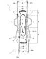
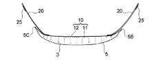
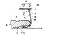
以下、本発明の吸収性物品を、その好ましい実施形態に基づき図面を参照して説明する。図1及び図2には、本発明の吸収性物品の第1実施形態としての生理用ナプキンが示されている。図3は、図1に示す生理用ナプキンから、後述する帯状部材20を取り除いた状態を示しており、図4は、図3のI−I線断面(2箇所)の模式図、図5は、図3のII−II線断面(2箇所)の模式図である。尚、図2においては、説明容易のため、帯状部材20を、斜め上方に引っ張った状態で記載している。  Hereinafter, the absorptive article of the present invention is explained based on the desirable embodiment with reference to drawings. The sanitary napkin as 1st Embodiment of the absorbent article of this invention is shown by FIG.1 and FIG.2. 3 shows a state in which a band-shaped member 20 described later is removed from the sanitary napkin shown in FIG. 1, FIG. 4 is a schematic diagram of a cross section taken along line II in FIG. 3 (FIG. 3), and FIG. FIG. 4 is a schematic diagram of a cross section (two places) taken along line II-II in FIG. 3. In FIG. 2, for ease of explanation, the band-like member 20 is illustrated in a state of being pulled obliquely upward.

第1実施形態のナプキン1は、着用時に着用者の肌に当接する表面層としての液透過性の表面シート2、防漏層としての液不透過性又は撥水性の裏面シート3、及びこれら両シート2,3間に介在された吸収層としての液保持性の吸収体4を有する縦長の本体5を備え、実質的に縦長の形状を有している。  Thenapkin 1 of the first embodiment includes a liquid-permeable surface sheet 2 as a surface layer that comes into contact with the wearer's skin when worn, a liquid-impermeable or water-repellent back sheet 3 as a leak-proof layer, and both A vertically longmain body 5 having a liquid retainingabsorbent body 4 as an absorbent layer interposed between thesheets 2 and 3 is provided, and has a substantially vertically long shape.

本体5は、着用時に着用者の排泄部位に対向配置される排泄部対向部Aと、該排泄部対向部Aよりも着用者の背側(後方)に配される後方部Bと、該排泄部対向部Aよりも着用者の腹側(前方)に配される前方部Cとを、長手方向に有している。後方部Bは、本体5の長手方向後端5Bを有しており、前方部Cは、本体5の長手方向前端5Cを有している。第1実施形態における排泄部対向部Aと後方部Bとの境界は、本体5の長手方向の略中央部に存する。前方部Cと排泄部対向部Aとの境界は、本体5の長手方向前端5Cから本体5の長手方向の全長の略20%に相当する距離離間した位置に存する。  Themain body 5 includes an excretory part facing part A disposed opposite to the excretion part of the wearer when worn, a rear part B disposed on the back side (rear) of the wearer with respect to the excretion part facing part A, and the excretion It has the front part C distribute | arranged to a wearer's belly side (front) rather than the part opposing part A in a longitudinal direction. The rear part B has a longitudinalrear end 5 </ b> B of themain body 5, and the front part C has alongitudinal front end 5 </ b> C of themain body 5. The boundary between the excretory part facing part A and the rear part B in the first embodiment exists in the substantially central part of themain body 5 in the longitudinal direction. The boundary between the front part C and the excretory part facing part A exists at a position spaced from thefront end 5C in the longitudinal direction of themain body 5 by a distance corresponding to approximately 20% of the total length in the longitudinal direction of themain body 5.

本体5は、その長手方向に沿う左右両側に、吸収体4の長手方向に沿う左右両側縁から該吸収体4の幅方向外方に延出した裏面シート3を含んで構成されるフラップ部を有している。フラップ部の肌当接面側は、不織布からなるシート(図示せず)により被覆されている。フラップ部は、後方部Bの所定箇所(後方部Bにおける本体5の長手方向後端5B寄りの部位)において、吸収体4の幅方向外方に向かって大きく膨らんでおり、これにより本体5の長手方向に沿う左右両側に、吸収体4の後方部Bにおける左右両側縁それぞれから幅方向外方に延出する一対の後部フラップ6,6が形成されている。また、フラップ部は、排泄部対向部Aにおいて吸収体4の幅方向外方に向かって大きく膨らんでおり、これにより本体5の長手方向に沿う左右両側に、吸収体4の排泄部対向部Aにおける長手方向に沿う左右両側縁それぞれから幅方向外方に延出する一対のウイング部7,7が形成されている。ウイング部7は、ナプキン1の着用時に下着のクロッチ部の外面側に折り返されて用いられる。  Themain body 5 has flap portions configured to includeback sheets 3 that extend outward in the width direction of theabsorber 4 from left and right side edges along the longitudinal direction of theabsorber 4 on both left and right sides along the longitudinal direction. Have. The skin contact surface side of the flap portion is covered with a sheet (not shown) made of a nonwoven fabric. The flap portion swells greatly outward in the width direction of theabsorbent body 4 at a predetermined portion of the rear portion B (a portion of the rear portion B near therear end 5B in the longitudinal direction of the main body 5). A pair ofrear flaps 6, 6 extending outward in the width direction from the left and right side edges of the rear part B of theabsorber 4 are formed on the left and right sides along the longitudinal direction. Moreover, the flap part is greatly bulging outward in the width direction of theabsorbent body 4 in the excretory part facing part A, and thereby the excretory part facing part A of theabsorbent body 4 on both the left and right sides along the longitudinal direction of themain body 5. A pair ofwing portions 7, 7 extending outward in the width direction from the left and right side edges along the longitudinal direction is formed. When thenapkin 1 is worn, thewing part 7 is folded and used on the outer surface side of the crotch part of the underwear.

表面シート2は、図4及び図5に示すように、吸収体4の上面(肌当接面側)の全域を被覆し、且つ吸収体4の長手方向両側縁を覆って裏面シート3側へ巻き込まれている。裏面シート3は、上述したように、吸収体4の下面(非肌当接面側)を被覆し、更に所定箇所において吸収体4の長手方向両側縁から幅方向外方に延出して、後部フラップ6及びウイング部7を形成している。表面シート2及び裏面シート3は、吸収体4の前後端から長手方向に延出し、その延出部分において互いにヒートシール等により接合されてエンドシール部8,8を形成している。表面シート2の肌当接面側には、表面シート2と吸収体4とが一体的に圧密化されて形成された防漏溝9が形成されている。防漏溝9は、例えばヒートエンボス加工により形成することができる。  As shown in FIGS. 4 and 5, thetop sheet 2 covers the entire area of the upper surface (skin contact surface side) of theabsorber 4 and covers both side edges in the longitudinal direction of theabsorber 4 toward theback sheet 3 side. It is involved. As described above, theback sheet 3 covers the lower surface (non-skin contact surface side) of theabsorbent body 4 and further extends outward in the width direction from both side edges in the longitudinal direction of theabsorbent body 4 at a predetermined location. Aflap 6 and awing portion 7 are formed. Thetop sheet 2 and theback sheet 3 extend in the longitudinal direction from the front and rear ends of theabsorbent body 4 and are joined to each other by heat sealing or the like at the extended portions to formend seal portions 8 and 8. On the skin contact surface side of thetop sheet 2, a leak-proof groove 9 formed by integrally compacting thetop sheet 2 and theabsorber 4 is formed. The leak-proof groove 9 can be formed by, for example, heat embossing.

裏面シート3の非肌当接面側の所定箇所には本体粘着部(図示せず)が、ウイング部8の非肌当接面側にはウイング部粘着部(図示せず)が、それぞれ設けられている。本体粘着部及びウイング部粘着部は、何れも本体5を下着に固定するための固定手段である。本体粘着部及びウイング部粘着部は、何れもホットメルト粘着剤を所定箇所に塗布することにより設けられている。本体粘着部及びウイング部粘着部それぞれにおける粘着剤の塗工量は、ナプキン1の過度な動きを抑制し、下着に対する固定性を高める観点から、20〜50g/m2であることが好ましい。
尚、本明細書において、「肌当接面側」は、ナプキン着用時に着用者の肌側に向けられる面であり、「非肌当接面側」は、ナプキン着用時に下着側(着用者の肌側とは反対側)に向けられる面である。また、「長手方向」は、ナプキン又は各種部材の長手方向に沿う方向であり、「幅方向」は、長手方向と直交する方向である。
A main body adhesive portion (not shown) is provided at a predetermined location on the non-skin contact surface side of theback sheet 3, and a wing portion adhesive portion (not shown) is provided on the non-skin contact surface side of thewing portion 8. It has been. Both the main body adhesive portion and the wing portion adhesive portion are fixing means for fixing themain body 5 to the undergarment. Both the main body adhesive portion and the wing portion adhesive portion are provided by applying a hot melt adhesive to a predetermined location. It is preferable that the coating amount of the adhesive in each of the main body adhesive part and the wing part adhesive part is 20 to 50 g / m2 from the viewpoint of suppressing excessive movement of thenapkin 1 and enhancing the fixability to the underwear.
In this specification, the “skin contact surface side” is a surface directed toward the wearer's skin when wearing a napkin, and the “non-skin contact surface side” is the underwear side (wearer's side) when wearing a napkin. The surface is directed to the side opposite to the skin side. The “longitudinal direction” is a direction along the longitudinal direction of the napkin or various members, and the “width direction” is a direction orthogonal to the longitudinal direction.

本体5の長手方向に沿う左右両側部には、該長手方向に沿って一対の立体ギャザー10,10が設けられている。各立体ギャザー10は、図3に示すように、本体5の長手方向の全長に亘って設けられている。
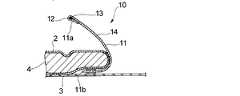
立体ギャザー10は、図3及び図4に示すように、本体5の肌当接面側に該本体5の長手方向に沿って起立する基壁部11と、該基壁部11の上端部11aに連接され、着用時に着用者の肌に当接する弾性伸縮部12とを含んで構成されている。弾性伸縮部12は、上端部11aの長手方向の全長に亘って連接されている。弾性伸縮部12には、本体5の長手方向に沿って側部弾性部材13が配されて弾性伸縮性が付与されている。立体ギャザー10(弾性伸縮部12)の伸縮方向は本体5の長手方向に一致している。側部弾性部材13は、少なくとも排泄部対向部Aに配されており、更に前方部C及び/又は後方部B側にも延びて配されていることが好ましい。
A pair of three-dimensional gathers 10 and 10 are provided along the longitudinal direction on both left and right side portions along the longitudinal direction of themain body 5. As shown in FIG. 3, each three-dimensional gather 10 is provided over the entire length of themain body 5 in the longitudinal direction.
As shown in FIGS. 3 and 4, the three-dimensional gather 10 includes abase wall portion 11 that stands on the skin contact surface side of themain body 5 along the longitudinal direction of themain body 5, and anupper end portion 11 a of thebase wall portion 11. And an elasticstretchable part 12 that contacts the wearer's skin when worn. The elastic expansion /contraction part 12 is connected over the full length of the longitudinal direction of theupper end part 11a. A sideelastic member 13 is disposed along the longitudinal direction of themain body 5 to the elasticstretchable portion 12 to impart elastic stretchability. The expansion / contraction direction of the three-dimensional gather 10 (elastic expansion / contraction part 12) coincides with the longitudinal direction of themain body 5. It is preferable that the sideelastic member 13 is arranged at least in the excretory part facing part A and further extends to the front part C and / or the rear part B side.

立体ギャザー10について更に説明すると、立体ギャザー10は、立体ギャザー形成用シート14を主体として構成されている。立体ギャザー形成用シート14は、長手方向に亘って一定の幅を有するシートで、基壁部11及びその上端部11aに弾性伸縮部12が連設された形状を有するように折り返されている。従って、立体ギャザー形成用シート14を折り返して形成された立体ギャザー10は、図4に示すように、基壁部11及び弾性伸縮部12において2層構造となっている。基壁部11の下端部11bは、吸収体4の非肌当接面側に巻き込まれている。吸収体4の非肌当接面側に巻き込まれた下端部11bは、吸収体4の非肌当接面側に巻き込まれた表面シート2の非肌当接面側と、裏面シート3の肌当接面側との間に、接着剤等の公知の接合手段により固定されている。  Thesolid gather 10 will be further described. The solid gather 10 is mainly composed of a solid gather formingsheet 14. The three-dimensional gather formingsheet 14 is a sheet having a constant width in the longitudinal direction, and is folded back so as to have a shape in which the elasticstretchable part 12 is continuously provided on thebase wall part 11 and itsupper end part 11a. Therefore, the three-dimensional gather 10 formed by folding the three-dimensional gather formingsheet 14 has a two-layer structure in thebase wall portion 11 and the elasticstretchable portion 12 as shown in FIG. Alower end portion 11 b of thebase wall portion 11 is wound around the non-skin contact surface side of theabsorber 4. Thelower end portion 11b entangled on the non-skin contact surface side of theabsorbent body 4 includes the non-skin contact surface side of thetop sheet 2 wound on the non-skin contact surface side of theabsorbent body 4 and the skin of theback sheet 3. Between the contact surface side, it is fixed by a known joining means such as an adhesive.

第1実施形態においては、弾性伸縮部12は、図4に示すように、基壁部11の上端部11aから水平方向に張り出しており、これにより、面状(ナプキン1の平面視において面状)に形成されている。即ち、弾性伸縮部12は、基壁部11の上端部11aから本体5の幅方向内方に略水平に張り出す内方弾性伸縮部12Aと、基壁部11の上端部11aから本体5の幅方向外方に略水平に張り出す外方弾性伸縮部12Bとから構成されており、少なくとも排泄部対向部Aにおいて着用者の肌に面状に当接するようになっている。内方弾性伸縮部12A及び外方弾性伸縮部12Bそれぞれには、側部弾性部材13が1本以上配されて弾性伸縮性が付与されている。側部弾性部材13は、それぞれ内方弾性伸縮部12A及び外方弾性伸縮部12Bを構成する2層の立体ギャザー形成用シート14,14の間に伸長状態で配されており、接着剤等の公知の手段によってこれら2層の立体ギャザー形成用シート14,14と接合されている。
このように、第1実施形態においては、内方弾性伸縮部12A及び外方弾性伸縮部12Bは、両者が一体となって平面状に形成され、弾性伸縮部12と基壁部11とは、図4に示す如き立体ギャザー10の幅方向(本体5の幅方向)の断面視において、T字状を形成している。
In the first embodiment, as shown in FIG. 4, the elasticstretchable portion 12 projects horizontally from theupper end portion 11 a of thebase wall portion 11, and thereby has a planar shape (planar shape in the plan view of the napkin 1). ). That is, the elastic expansion /contraction part 12 includes an inward elastic expansion /contraction part 12A projecting substantially horizontally from theupper end part 11a of thebase wall part 11 in the width direction of themain body 5 and theupper end part 11a of thebase wall part 11 from theupper end part 11a. It is comprised from the outward elastic expansion-contraction part 12B which protrudes in the width direction outward substantially horizontal, and contacts the wearer's skin at least in the excretion part opposing part A at least. One or more sideelastic members 13 are arranged on each of the inward elastic expansion /contraction part 12A and the outward elastic expansion /contraction part 12B to give elastic elasticity. The sideelastic members 13 are arranged in an extended state between the two layers of three-dimensional gather formingsheets 14 and 14 constituting the inner elastic expansion /contraction part 12A and the outer elastic expansion /contraction part 12B, respectively. These two layers of three-dimensional gather formingsheets 14 and 14 are joined by a known means.
As described above, in the first embodiment, the inner elastic expansion /contraction part 12A and the outer elastic expansion /contraction part 12B are integrally formed in a planar shape, and the elastic expansion /contraction part 12 and thebase wall part 11 are: In a cross-sectional view in the width direction (width direction of the main body 5) of the three-dimensional gather 10 as shown in FIG. 4, a T-shape is formed.

第1実施形態においては、内方弾性伸縮部12A及び外方弾性伸縮部12Bの張り出し幅は異なっている。内方弾性伸縮部12Aの張り出し幅と外方弾性伸縮部12Bの張り出し幅との比(前者:後者)は、好ましくは1:5〜5:1であり、特に、弾性伸縮部12の本体5の内方への張り出しによる液吸収面の面積縮小を防止し、該液吸収面を幅方向に広くできる点から、更に好ましくは1:1〜1:4である。
また、内方弾性伸縮部12Aの長手方向に沿った自由端から外方弾性伸縮部12Bの長手方向に沿った自由端までの長さ、即ち、面状の弾性伸縮部12の幅は、フィット性及び立体ギャザー10を汚しにくくする点から、10〜50mmが好ましい。
In the first embodiment, the projecting widths of the inner elasticstretchable portion 12A and the outer elasticstretchable portion 12B are different. The ratio of the overhanging width of the inward elastic expansion /contraction part 12A to the overhanging width of the outer elastic expansion /contraction part 12B (the former: the latter) is preferably 1: 5 to 5: 1, and in particular, themain body 5 of the elastic expansion /contraction part 12 It is more preferably 1: 1 to 1: 4 from the viewpoint that the area of the liquid absorption surface can be prevented from being reduced due to the inward extension of the liquid and the liquid absorption surface can be widened in the width direction.
Further, the length from the free end along the longitudinal direction of the inner elasticstretchable portion 12A to the free end along the longitudinal direction of the outer elasticstretchable portion 12B, that is, the width of the planar elasticstretchable portion 12 is fit. 10-50 mm is preferable from the point which makes a property and the solid gathers 10 difficult to get dirty.

立体ギャザー10は、図3及び図5に示すように、弾性伸縮部12が本体5に接合されている弾性伸縮部固定部15を有している。弾性伸縮部固定部15においては、弾性伸縮部12が本体5に接合されていることで基壁部11の起立が阻害されているため、立体ギャザー10は起立していない。
第1実施形態においては、弾性伸縮部固定部15は、立体ギャザー10(弾性伸縮部12)の長手方向両端部に形成されており、これら両端部に挟まれた立体ギャザー10の長手方向内方部には形成されていない。この弾性伸縮部固定部15の形成領域は、本体5の長手方向両端部、具体的には、前方部Cの略全域及び後方部Bにおける本体5の長手方向後端5B寄りの領域に一致する。つまり、立体ギャザー10は、弾性伸縮部固定部15が形成されている本体5の長手方向両端部においては起立しておらず、弾性伸縮部固定部15が形成されていない、排泄部対向部A及び後方部Bの該排泄部対向部A寄りの領域においては、側部弾性部材13による収縮力によって起立している。また、弾性伸縮部12の収縮によって、本体5は、その長手方向の全体形状が、図2に示すように肌当接面側(表面シート2側)に凹状に湾曲している。
As shown in FIGS. 3 and 5, the three-dimensional gather 10 has an elastic stretchableportion fixing portion 15 in which an elasticstretchable portion 12 is joined to themain body 5. In the elastic expansion / contraction part fixing | fixedpart 15, since the standing extension of thebase wall part 11 is inhibited because the elastic expansion /contraction part 12 is joined to themain body 5, the solid gathers 10 do not stand up.
In 1st Embodiment, the elastic expansion-contraction part fixing | fixedpart 15 is formed in the longitudinal direction both ends of the three-dimensional gather 10 (elastic expansion-contraction part 12), and the longitudinal direction inner side of the three-dimensional gather 10 pinched | interposed into these both ends It is not formed in the part. The formation region of the elastic expansion / contractionportion fixing portion 15 coincides with both ends of themain body 5 in the longitudinal direction, specifically, substantially the entire region of the front portion C and the region near therear end 5B of themain body 5 in the rear portion B. . That is, the three-dimensional gather 10 does not stand up at both ends in the longitudinal direction of themain body 5 where the elastic expansion / contractionpart fixing part 15 is formed, and the excretion part facing part A where the elastic expansion / contractionpart fixing part 15 is not formed. And in the region of the rear part B near the excretory part facing part A, it stands up due to the contraction force by the sideelastic member 13. Further, due to the contraction of the elasticstretchable portion 12, the overall shape of themain body 5 in the longitudinal direction is concavely curved toward the skin contact surface side (surface sheet 2 side) as shown in FIG.

弾性伸縮部固定部15は、図5に示すように、弾性伸縮部12の少なくとも幅方向内側(内方弾性伸縮部12A)が、折り重ねられた基壁部11を介して、本体5を構成する表面シート2及びエンドシール部8に固定されることで形成されている。
弾性伸縮部固定部15の長手方向(弾性伸縮部12の長手方向と平行な方向)の長さL1は、弾性伸縮部12の長手方向の全長に対して、好ましくは1〜40%、更に好ましくは20〜30%である。L1が弾性伸縮部12の全長との関係でこの範囲とされることで、ナプキン1の長手方向前後端部のフィット性が損なわれ難くなる。
尚、ナプキン1に該ナプキン1を下着に固定するための粘着部(前記本体粘着部、前記ウイング部粘着部)を配する場合、該粘着部は、弾性伸縮部固定部15の形成領域(図3中では符号L1で示される領域)及び該形成領域よりも本体長手方向外方に位置する領域には配されていないことが、立体ギャザー10の起立性や倒れこみ防止性を維持する観点から好ましい。
As shown in FIG. 5, the elastic stretchableportion fixing portion 15 constitutes themain body 5 via abase wall portion 11 in which at least the inner side in the width direction (inner elasticstretchable portion 12A) of the elasticstretchable portion 12 is folded. It is formed by being fixed to thesurface sheet 2 and theend seal part 8 to be performed.
The length L1 in the longitudinal direction (the direction parallel to the longitudinal direction of the elastic expansion / contraction part 12) of the elastic expansion / contractionpart fixing part 15 is preferably 1 to 40%, more preferably the total length in the longitudinal direction of the elastic expansion /contraction part 12 Is 20-30%. By making L1 within this range in relation to the total length of the elasticstretchable part 12, the fit property of the front and rear end parts in the longitudinal direction of thenapkin 1 is unlikely to be impaired.
In addition, when the adhesive part (the said main body adhesive part, the said wing part adhesive part) for fixing thisnapkin 1 to underwear is arranged on thenapkin 1, this adhesive part is a formation area | region (FIG. 3 is a region that is located outside the longitudinal direction of the main body with respect to the formation region), and from the viewpoint of maintaining the standing property of the three-dimensional gather 10 and the fall-preventing property. preferable.

立体ギャザー10の長手方向一端側及び他端側それぞれの弾性伸縮部12には、図1に示すように、立体ギャザー10の長手方向(本体5の長手方向)に延びる帯状部材20が接合されている。つまり、本発明においては、立体ギャザー10(弾性伸縮部12)の長手方向を二分する仮想線(図示せず)によって分けられる、弾性伸縮部12の長手方向一端側領域及び他端側領域それぞれに、立体ギャザー10の長手方向に延びる帯状部材20が接合され、一の立体ギャザー10につき少なくとも2本の帯状部材20が接合される。
帯状部材20は、他の部材に接合されていない自由端部20aを有しており、該自由端部20aの非肌当接面側に、該帯状部材20を着用者の下着に固定する固定手段25が設けられている。尚、図1及び図3中の符号S(斜線部)は、弾性伸縮部12と帯状部材20との接合部を示している。
As shown in FIG. 1, a band-like member 20 extending in the longitudinal direction of the three-dimensional gather 10 (longitudinal direction of the main body 5) is joined to the elasticstretchable portions 12 on one end side and the other end side of the three-dimensional gather 10. Yes. That is, in the present invention, each of the one end side region and the other end side region of the elasticstretchable portion 12 is divided by a virtual line (not shown) that bisects the longitudinal direction of the three-dimensional gather 10 (elastic stretchable portion 12). The belt-like members 20 extending in the longitudinal direction of the three-dimensional gather 10 are joined, and at least two belt-like members 20 are joined to one solid gather 10.
The belt-like member 20 has afree end 20a that is not joined to another member, and is fixed to the underwear of the wearer on the non-skin contact surface side of thefree end 20a. Means 25 are provided. In FIG. 1 and FIG. 3, a symbol S (shaded portion) indicates a joint portion between the elasticstretchable portion 12 and the belt-like member 20.

帯状部材20は、ナプキン1の着用時に自由端部20aを介して着用者の下着又は肌に固定されて使用されるもので、該帯状部材20が立体ギャザー10を構成する弾性伸縮部12に上述の如く接合されていることにより、立体ギャザー10と着用者の下着又は肌とを該立体ギャザー10の長手方向(弾性伸縮部12の長手方向)に沿って連結させることが可能となり、これにより、立体ギャザー10の身体に対する追従性が高まり、立体ギャザー10の倒れ込みやズレ、ヨレを効果的に防止することができ、また万一、身体の過度な動きによって立体ギャザー10の倒れ込みやズレ、ヨレ等が生じても、立体ギャザー10を適切な状態に復帰させることができる。  The band-shapedmember 20 is used by being fixed to the wearer's underwear or skin via thefree end 20 a when thenapkin 1 is worn, and the band-shapedmember 20 is formed on the elasticstretchable part 12 constituting the three-dimensional gather 10. It is possible to connect the three-dimensional gather 10 and the wearer's underwear or skin along the longitudinal direction of the three-dimensional gather 10 (longitudinal direction of the elastic stretchable portion 12). The follow-up performance of the three-dimensional gather 10 to the body is enhanced, and the three-dimensional gather 10 can be effectively prevented from falling, shifting, and twisting. In the unlikely event of the excessive movement of the body, the three-dimensional gather 10 is tilted, displaced, twisted, etc. Even if this occurs, the three-dimensional gather 10 can be returned to an appropriate state.

第1実施形態においては、立体ギャザー10の長手方向一端側(本体5の長手方向前端5C側)に接合され、前端5Cから本体5の長手方向外方へ延出する帯状部材20と、立体ギャザー10の長手方向他端側(本体5の長手方向後端5B側)に接合され、後端5Bから本体5の長手方向外方へ延出する帯状部材20とがそれぞれ2本ずつあり、第1実施形態のナプキン1は、計4本の帯状部材20を具備している。各帯状部材20は、その長手方向一端が弾性伸縮部12に接合されて固定端とされ、長手方向他端が他の部材に接合されていない自由端とされており、該自由端の近傍に固定手段25が配されている。  In the first embodiment, a belt-like member 20 joined to one end side in the longitudinal direction of the three-dimensional gather 10 (on thefront end 5C side in the longitudinal direction of the main body 5) and extending outward from thefront end 5C in the longitudinal direction of themain body 5; There are two belt-like members 20 that are joined to the other longitudinal end side (longitudinalrear end 5B side of the main body 5) 10 and extend outward from therear end 5B in the longitudinal direction of themain body 5. Thenapkin 1 according to the embodiment includes a total of four belt-like members 20. Each belt-like member 20 has one end in the longitudinal direction joined to the elastic expansion /contraction part 12 as a fixed end, and the other end in the longitudinal direction is a free end that is not joined to another member, in the vicinity of the free end. Fixing means 25 is arranged.

帯状部材20の幅は、弾性伸縮部材12との接合の容易さ、帯状部材20の下着や身体への固定性、及び着用時のナプキンの安定性の観点から、弾性伸縮部12の幅に対して、好ましくは50〜150%、更に好ましくは80〜120%である。
帯状部材20の長さ(長手方向の長さ)は、本体5のサイズやナプキン1と併用される下着のサイズ等により適宜調整することができ特に制限されないが、帯状部材20の自由端部20aを摘んで、弾性伸縮部材12との接合部Sに最も近い位置にある本体長手方向の端縁(前端5C又は後端5B)からナプキン長手方向外方に向けて引っ張った時に、該端縁から延出し得る長さが好ましく、好ましくは1〜10cmである。帯状部材20の厚みは、好ましくは0.5〜5mm、更に好ましくは1〜3mmである。
本体5に接合されている複数の帯状部材20は、各寸法(幅、長さ、厚み)が異なっていても良く、全て同じであっても良い。
The width of the belt-shapedmember 20 is set to the width of the elasticstretchable portion 12 from the viewpoint of ease of joining with the elasticstretchable member 12, fixing to the underwear and body of the strip-shapedmember 20, and stability of the napkin when worn. Therefore, it is preferably 50 to 150%, more preferably 80 to 120%.
The length (length in the longitudinal direction) of the band-shapedmember 20 can be appropriately adjusted depending on the size of themain body 5 and the size of the underwear used in combination with thenapkin 1, but is not particularly limited, but thefree end 20a of the band-shapedmember 20 , And pulled from the edge of the main body longitudinal direction (front end 5C orrear end 5B) closest to the joint S to the elasticelastic member 12 outward in the napkin longitudinal direction. The length which can be extended is preferable, Preferably it is 1-10 cm. The thickness of the band-shapedmember 20 is preferably 0.5 to 5 mm, more preferably 1 to 3 mm.
The plurality of belt-like members 20 joined to themain body 5 may have different dimensions (width, length, thickness), or may all be the same.

帯状部材20としては、例えば、エンボスを施されたウレタンフィルム等の弾性部材;不織布間に接着剤や熱接合によって弾性糸が固定された伸張部材;ウレタン材料と貼り合わされた布地;衣類のウエスト部に使用されるゴム紐等を用いることができる。これらの中でも、接合が容易な点から、合成樹脂材料を有し弾性伸縮性を有するものが好ましく、特に、不織布間に弾性部材を固定した各種伸縮性シートが好ましい。  Examples of the band-shapedmember 20 include an elastic member such as an embossed urethane film; an extension member in which elastic yarn is fixed by adhesive or heat bonding between nonwoven fabrics; a fabric bonded with a urethane material; a waist portion of clothing The rubber string etc. which are used for can be used. Among these, from the viewpoint of easy joining, those having a synthetic resin material and elastic elasticity are preferable, and various elastic sheets in which an elastic member is fixed between nonwoven fabrics are particularly preferable.

帯状部材20は、吸収体4の上方にて弾性伸縮部12に接合されていることが好ましい。帯状部材20が吸収体4の上方にて弾性伸縮部12に接合されている形態は、帯状部材20が吸収体4の幅方向外方や長手方向外方にて弾性伸縮部12に接合されている形態に比して、立体ギャザー10の身体に対する追従性に優れており、このため万一、身体の過度な動きによって立体ギャザー10の倒れ込みやズレ、ヨレ等が生じても、このような立体ギャザー10の不適切な状態を適切な状態に速やかに戻すことができる。  The belt-like member 20 is preferably joined to the elasticstretchable part 12 above theabsorber 4. In the form in which the band-shapedmember 20 is joined to the elasticstretchable part 12 above theabsorber 4, the band-shapedmember 20 is joined to the elasticstretchable part 12 on the outer side in the width direction or the longitudinal direction of theabsorbent body 4. The three-dimensional gather 10 has excellent followability to the body as compared with the existing form. For this reason, even if the three-dimensional gather 10 falls down, shifts, or twists due to excessive body movement, An inappropriate state of the gather 10 can be quickly returned to an appropriate state.

帯状部材20の弾性伸縮部12との接合形態は、下記1)〜3)から選択することができる。即ち、帯状部材20は、1)本体5に接合されていない弾性伸縮部12(弾性伸縮部固定部15を形成していない弾性伸縮部12)に接合されていても良く、2)弾性伸縮部固定部15(本体5に接合されている弾性伸縮部12)に接合されていても良く、3)本体5に接合されていない弾性伸縮部12及び弾性伸縮部固定部15の両方に接合されていても良い。
前記1)の形態、即ち、帯状部材20が、起立する立体ギャザー10を構成する弾性伸縮部12に接合されている形態は、特に、立体ギャザー10の身体に対する追従性に優れており、身体が動いても立体ギャザー10が身体から離れずに密着する。
また、前記2)の形態、即ち、帯状部材20が、起立しない立体ギャザー10を構成する弾性伸縮部12に接合されている形態は、特に、本体5の長手方向前後端部の身体に対するフィット性に優れている。
また、前記3)の形態、即ち、前記1)及び前記2)の両方を具備する形態は、上述した特長がバランス良く備わっており、立体ギャザーの身体に対する密着性及びナプキンのフィット性の点で良好な結果が得られる。
第1実施形態においては、前記3)の形態が採用されており、弾性伸縮部12と帯状部材20との接合部Sは、弾性伸縮部固定部15と弾性伸縮部12が本体5に接合されていない領域における該弾性伸縮部12との境界を跨ぐように配されている。
The joining form with the elasticelastic part 12 of the strip | belt-shapedmember 20 can be selected from the following 1) -3). That is, the belt-like member 20 may be joined to 1) an elasticstretchable part 12 that is not joined to the main body 5 (elasticstretchable part 12 that does not form the elastic stretchable part fixing part 15). It may be joined to the fixing portion 15 (the elasticstretchable portion 12 joined to the main body 5). 3) It is joined to both the elasticstretchable portion 12 and the elastic stretchableportion fixing portion 15 that are not joined to themain body 5. May be.
The form of 1) above, that is, the form in which the belt-like member 20 is joined to the elasticstretchable part 12 constituting the standing three-dimensional gather 10, is particularly excellent in the followability of the three-dimensional gather 10 to the body. Even if it moves, the solid gathers 10 are in close contact without leaving the body.
Moreover, the form of said 2), ie, the form by which the strip | belt-shapedmember 20 is joined to the elastic expansion-contraction part 12 which comprises the solid gathers 10 which do not stand up, especially fit property with respect to the body of the longitudinal direction front-and-back end part of themain body 5 is. Is excellent.
In addition, the above-mentioned 3) form, that is, the form comprising both of the above 1) and 2) has the above-mentioned features in a well-balanced manner in terms of the adhesion of the three-dimensional gather to the body and the fit of the napkin. Good results are obtained.
In the first embodiment, the above-described form 3) is employed, and the elastic expansion /contraction part 12 and theelastic member 12 are bonded to themain body 5 at the joint S between the elastic expansion /contraction part 12 and the belt-like member 20. It arrange | positions so that the boundary with this elastic expansion-contraction part 12 in the area | region which is not may be straddled.

弾性伸縮部12と帯状部材20との接合部Sの長手方向の長さ(弾性伸縮部12の長手方向に沿った長さ)L2は、弾性伸縮部12の長手方向の全長に対して、好ましくは5〜30%、更に好ましくは10〜20%の範囲にあることが、接合部Sの強度が強く、且つ弾性伸縮部12の弾性挙動を阻害しない点で好ましい。
また、接合部Sの長手方向の長さL2は、帯状部材20の長手方向の全長に対して、好ましくは5〜30%、更に好ましくは10〜20%の範囲にあることが、弾性伸縮部12の弾性挙動を阻害しない点で好ましい。尚、帯状部材20における接合部Sの位置は、第1実施形態のように、帯状部材20の長手方向一端(自由端部20aと反対側の端部の端)であることが好ましい。
接合部Sの幅は、通常、弾性伸縮部12及び帯状部材20のうち、相対的に幅狭の部材の幅に略等しく設定される。弾性伸縮部12と帯状部材20との接合(接合部Sの形成)は、接着剤、ヒートシール、超音波シール等の公知の接合手段を行なうことができる。接合においては、帯状部材20の内側縁(相対的に本体5の幅方向内方寄りにある側縁)が弾性伸縮部材12よりはみ出さず、且つ帯状部材20の外側縁(相対的に本体5の幅方向外方寄りにある側縁)が、弾性伸縮部材12の外側縁と等しいか、又は該外側縁を越える程度に接合されていることが、立体ギャザー10の倒れこみ防止の観点から好ましい。
The length in the longitudinal direction (length along the longitudinal direction of the elastic stretchable portion 12) L2 of the joint portion S between the elasticstretchable portion 12 and the belt-like member 20 is preferably relative to the overall length of the elasticstretchable portion 12 in the longitudinal direction. Is preferably in the range of 5 to 30%, more preferably 10 to 20% in that the strength of the joint portion S is strong and the elastic behavior of the elasticstretchable portion 12 is not hindered.
Further, the length L2 in the longitudinal direction of the joint portion S is preferably in the range of 5 to 30%, more preferably in the range of 10 to 20% with respect to the total length in the longitudinal direction of the band-shapedmember 20. 12 is preferable in that the elastic behavior of 12 is not hindered. In addition, it is preferable that the position of the junction part S in the strip | belt-shapedmember 20 is the longitudinal direction end (end of the edge part on the opposite side to thefree end part 20a) of the strip | belt-shapedmember 20 like 1st Embodiment.
The width of the joint portion S is normally set to be approximately equal to the width of the relatively narrow member of the elasticstretchable portion 12 and the band-shapedmember 20. The elasticstretchable part 12 and the band-like member 20 can be joined (formation of the joined part S) by a known joining means such as an adhesive, heat seal, ultrasonic seal or the like. In joining, the inner edge of the band-shaped member 20 (the side edge relatively inward in the width direction of the main body 5) does not protrude from the elasticelastic member 12, and the outer edge of the band-shaped member 20 (relatively the main body 5). It is preferable from the viewpoint of preventing the collapse of the three-dimensional gathers 10 that the side edges on the outer side in the width direction are equal to the outer edge of the elasticelastic member 12 or are joined to the extent that the outer edge is exceeded. .

帯状部材20に設けられている固定手段25としては、ナプキン着用者の下着に帯状部材20を接離自在に固定し得るものが用いられ、例えば、ホットメルト粘着剤、メカニカルファスナーのオス材等を用いることができる。
尚、帯状部材20をナプキン着用者の肌に固定させる場合、固定手段25としては、粘着剤等が用いられ、また斯かる場合には、自由端部20aの肌当接面側に固定手段25を設けることが好ましい。また、固定手段25は、前記本体粘着部及びウイング部粘着部(図示せず)に比して粘着力が低いことが好ましい。具体的には、固定手段25は、T剥離法による下着生地への粘着力が10〜50%であることが、肌へのダメージを防ぐ観点から好ましい。
As the fixing means 25 provided in the belt-like member 20, those that can fix the belt-like member 20 to the underwear of the napkin wearer are used. For example, hot melt adhesive, male material of a mechanical fastener, etc. Can be used.
In addition, when fixing the strip | belt-shapedmember 20 to a skin of a napkin wearer, an adhesive etc. are used as the fixing means 25, and in such a case, the fixing means 25 is provided on the skin contact surface side of thefree end 20a. Is preferably provided. Moreover, it is preferable that the fixing means 25 has low adhesive force compared with the said main body adhesion part and a wing part adhesion part (not shown). Specifically, the fixing means 25 preferably has an adhesive force to the underwear fabric by the T peeling method of 10 to 50% from the viewpoint of preventing damage to the skin.

固定手段25の長手方向の長さ(弾性伸縮部12の長手方向に沿った長さ)L3は、弾性伸縮部12の長手方向の全長に対して、好ましくは5〜50%、更に好ましくは10〜20%である。また、固定手段25の幅は、弾性伸縮部12の幅に対して、好ましくは50〜100%、更に好ましくは80〜100%である。
固定手段25は、帯状部材20の自由端から該帯状部材20の長手方向の全長の0〜10%に亘る領域に設けられることが好ましい。
The length L3 in the longitudinal direction of the fixing means 25 (the length along the longitudinal direction of the elastic stretchable portion 12) L3 is preferably 5 to 50%, more preferably 10 with respect to the total length of the elasticstretchable portion 12 in the longitudinal direction. ~ 20%. The width of the fixing means 25 is preferably 50 to 100%, more preferably 80 to 100% with respect to the width of the elasticstretchable part 12.
The fixing means 25 is preferably provided in a region extending from the free end of the band-shapedmember 20 to 0 to 10% of the entire length in the longitudinal direction of the band-shapedmember 20.

本実施形態のナプキン1における表面シート2、裏面シート3及び吸収体4としては、生理用ナプキン等の吸収性物品において従来から用いられている各種材料を特に制限なく用いることができる。
表面シート2としては、例えば、親水化処理が施された各種不織布や開孔フィルム等の液透過性のシートを用いることができる。裏面シート3としては、例えば、熱可塑性樹脂のフィルム(ポリエチレンフィルム等)や、該フィルムと不織布とのラミネート等の液不透過性又は撥水性のシートを用いることができ、水蒸気透過性を有するものを用いることもできる。
吸収体4としては、生理用ナプキン等の吸収性物品における吸収体として従来から用いられている各種材料を特に制限なく用いることができ、例えば、パルプ繊維を堆積させて得られた積繊層、パルプ繊維を原料とする不織布からなるものを用いることができる。吸収体4は吸収性ポリマーを含有していても良い。また、吸収体4は、ティッシュペーパー等の紙や各種不織布等のシート材で被覆されていても良い。
As thetop sheet 2, theback sheet 3 and theabsorbent body 4 in thenapkin 1 of the present embodiment, various materials conventionally used in absorbent articles such as sanitary napkins can be used without particular limitation.
As thesurface sheet 2, for example, liquid permeable sheets such as various nonwoven fabrics and perforated films subjected to a hydrophilic treatment can be used. As theback sheet 3, for example, a liquid-impermeable or water-repellent sheet such as a thermoplastic resin film (polyethylene film or the like) or a laminate of the film and a nonwoven fabric can be used, and has water vapor permeability. Can also be used.
As theabsorbent body 4, various materials conventionally used as absorbent bodies in absorbent articles such as sanitary napkins can be used without particular limitation, for example, a pile layer obtained by depositing pulp fibers, What consists of a nonwoven fabric which uses a pulp fiber as a raw material can be used. Theabsorber 4 may contain an absorbent polymer. Moreover, theabsorber 4 may be coat | covered with sheet materials, such as paper, such as tissue paper, and various nonwoven fabrics.

弾性伸縮部12に配される側部弾性部材13としては、弾性を有しているものであれば、糸状の弾性部材に制限されず、帯状のものでもよい。
立体ギャザー形成用シート14としては、生理用ナプキン等の吸収性物品における立体ギャザーを構成する材料として従来から用いられている材料を特に制限なく用いることができ、特に好ましくは疎水性不織布等の撥水性のシートが用いられる。
また、立体ギャザー10は、第1実施形態においては基壁部11と弾性伸縮部12とが一体的に形成されているが、基壁部11と弾性伸縮部12とを別々に製造し、それらを接合して形成することもできる。
As long as it has elasticity, as the side partelastic member 13 distribute | arranged to the elastic expansion-contraction part 12, it is not restricted to a thread-like elastic member, A strip | belt shape may be sufficient.
As the three-dimensional gather formingsheet 14, a material conventionally used as a material constituting a three-dimensional gather in an absorbent article such as a sanitary napkin can be used without any particular limitation, and particularly preferably a repellent material such as a hydrophobic nonwoven fabric. An aqueous sheet is used.
Further, in the first embodiment, the three-dimensional gather 10 has thebase wall portion 11 and the elasticstretchable portion 12 integrally formed. However, thebase wall portion 11 and the elasticstretchable portion 12 are separately manufactured, and these Can also be formed.

第1実施形態のナプキン1の着用に際しては、先ず、本体5の非肌当接面側に設けられている本体粘着部及びウイング部粘着部(図示せず)によって、本体5を着用者が着用している下着の肌当接面上に固定する。このとき、本体5の長手方向(立体ギャザー10の長手方向)が着用者の前後方向に一致し且つ排泄部対向部Aが着用者の排泄部位に対向するようにナプキン1を固定する。この本体5の固定作業は、この種の生理用ナプキンの着用作業と同じである。次いで、帯状部材20の自由端部20aを摘んで立体ギャザー10の長手方向に沿って上方に向けて引っ張ることで、帯状部材20を弛みが無い状態にし、この状態で帯状部材20の固定手段25を下着に固定する。帯状部材20の長さや下着のサイズ等にもよるが、通常、固定手段25は下着のウエスト部又はその近傍に固定される。こうしてナプキン1を下着に固定して使用することができる。  When wearing thenapkin 1 of the first embodiment, first, the wearer wears themain body 5 by the main body adhesive portion and the wing portion adhesive portion (not shown) provided on the non-skin contact surface side of themain body 5. Fix it on the skin contact surface of the underwear. At this time, thenapkin 1 is fixed so that the longitudinal direction of the main body 5 (longitudinal direction of the three-dimensional gather 10) coincides with the wearer's front-rear direction and the excretory part facing part A faces the excretion part of the wearer. The operation of fixing themain body 5 is the same as the operation of wearing this type of sanitary napkin. Next, thefree end portion 20a of the band-shapedmember 20 is picked and pulled upward along the longitudinal direction of the three-dimensional gather 10, so that the band-shapedmember 20 is not loosened, and in this state, the fixing means 25 for the band-shapedmember 20 is secured. To the underwear. Although it depends on the length of the belt-like member 20 and the size of the underwear, the fixing means 25 is usually fixed to the waist portion of the underwear or the vicinity thereof. Thus, thenapkin 1 can be used while being fixed to the undergarment.

第1実施形態のナプキン1によれば、着用者の下着又は肌に固定可能な帯状部材20が、立体ギャザー10の構成部材である弾性伸縮部12に接合されているため、立体ギャザー10の身体に対する追従性に優れており、就寝時や運動時のように着用者の身体の動きが激しい場合でも、立体ギャザー10が身体に密着し、立体ギャザー10の倒れ込みやズレ、ヨレが効果的に抑制され、横漏れを生じ難い。  According to thenapkin 1 of the first embodiment, since the belt-like member 20 that can be fixed to the wearer's underwear or skin is joined to the elasticstretchable part 12 that is a constituent member of the three-dimensional gather 10, the body of the three-dimensional gather 10 Even when the wearer's body moves violently, such as when sleeping or exercising, the three-dimensional gathers 10 are in close contact with the body, and the three-dimensional gathers 10 are effectively prevented from falling, shifting or twisting. It is difficult to cause side leakage.

また、帯状部材20を、吸収体4の上方にて弾性伸縮部12に接合させることは、特に、立体ギャザー10の身体に対する追従性の向上に有効であり、これにより、身体の過度な動きによって立体ギャザー10の倒れ込みやズレ、ヨレ等が生じても、このような立体ギャザー10の不適切な状態を適切な状態に速やかに戻すことができる。
また、帯状部材20を、本体5に接合されていない弾性伸縮部12に接合させることも、立体ギャザー10の身体に対する追従性の向上に有効であり、立体ギャザー10の身体に対する密着性が向上する。
また、帯状部材20を、弾性伸縮部固定部15に接合させることは、特に、本体5の長手方向前後部の身体に対するフィット性の向上に有効である。
また、弾性伸縮部12が、図4に示す如く面状に形成されていることは、着用感の向上に特に有効である。
In addition, joining the belt-like member 20 to the elasticstretchable part 12 above theabsorber 4 is particularly effective in improving the followability of the three-dimensional gather 10 to the body, thereby causing excessive movement of the body. Even if the three-dimensional gather 10 falls down, shifts, twists, or the like, such an inappropriate state of the three-dimensional gather 10 can be quickly returned to an appropriate state.
Also, joining the belt-like member 20 to the elasticstretchable part 12 that is not joined to themain body 5 is effective in improving the followability of the three-dimensional gather 10 to the body, and the adhesion of the three-dimensional gather 10 to the body is improved. .
Further, joining the belt-like member 20 to the elastic stretchablepart fixing part 15 is particularly effective for improving the fit of themain body 5 with respect to the front and rear parts in the longitudinal direction.
Moreover, it is especially effective for the improvement of a feeling of wear that the elastic expansion-contraction part 12 is formed in planar shape as shown in FIG.

以下、本発明の他の実施形態について図6〜図8を参照して説明する。後述する他の実施形態については、上述した第1実施形態のナプキン1と異なる構成部分を主として説明し、同様の構成部分は同一の符号を付して説明を省略する。特に説明しない構成部分は、第1実施形態のナプキン1についての説明が適宜適用される。  Hereinafter, another embodiment of the present invention will be described with reference to FIGS. Regarding other embodiments to be described later, components that are different from thenapkin 1 of the first embodiment described above will be mainly described, and similar components will be denoted by the same reference numerals and description thereof will be omitted. The description about thenapkin 1 of 1st Embodiment is applied suitably to the component which is not demonstrated especially.

図6には、第2実施形態のナプキン1の図4相当図が示されている。第2実施形態のナプキン1は、弾性伸縮部12が、基壁部11の上端部11aから本体5の幅方向外方に略水平に張り出す外方弾性伸縮部のみから構成されている点で、第1実施形態と異なる。但し、第2実施形態における弾性伸縮部12も、面状に形成されているという点では第1実施形態と同じであり、第2実施形態によっても、第1実施形態と同様の効果が奏される。  FIG. 6 shows a view corresponding to FIG. 4 of thenapkin 1 of the second embodiment. Thenapkin 1 of 2nd Embodiment is the point by which the elastic expansion-contraction part 12 is comprised only from the outward elastic expansion-contraction part extended substantially horizontally from theupper end part 11a of thebase wall part 11 to the width direction outer side of themain body 5. This is different from the first embodiment. However, the elastic expansion /contraction part 12 in the second embodiment is the same as that of the first embodiment in that it is formed in a planar shape, and the same effect as that of the first embodiment is achieved by the second embodiment. The

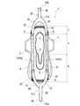
図7には、第3実施形態のナプキン1の図1相当図が示されている。第3実施形態のナプキン1は、第1実施形態に比して帯状部材20の形状が異なっており、本体5の長手方向一端側及び他端側それぞれに、一対の立体ギャザー10,10の両方と接合し、本体5の長手方向外方に延びる略Y字状の一の帯状部材20が接合されている。
即ち、第3実施形態においては、一対の立体ギャザー10,10の長手方向一端側(本体5の長手方向前端5C側)及び他端側(本体5の長手方向後端5B側)それぞれにおいて、一方の立体ギャザー10(弾性伸縮部12)に接合されている帯状部材20と、他方の立体ギャザー10(弾性伸縮部12)に接合されている帯状部材20とが合流し、本体5の長手方向外方に向かって凸のU字状湾曲部21と、該U字状湾曲部21の頂部21aから本体5の長手方向外方に向かって延びる一の直線状部22とを形成しており、該直線状部22が自由端部20aを有している。U字状湾曲部21の頂部21aは、本体5の幅方向中央に位置している。
FIG. 7 shows a view corresponding to FIG. 1 of thenapkin 1 of the third embodiment. Thenapkin 1 of the third embodiment is different from the first embodiment in the shape of the band-like member 20, and both the pair of three-dimensional gathers 10, 10 are provided on one end side and the other end side in the longitudinal direction of themain body 5. And one belt-like member 20 that is substantially Y-shaped and extends outward in the longitudinal direction of themain body 5 is joined.
That is, in the third embodiment, each of the pair of three-dimensional gathers 10 and 10 on one end side in the longitudinal direction (on thefront end 5C side in the longitudinal direction of the main body 5) and on the other end side (on therear end 5B in the longitudinal direction of the main body 5) The belt-like member 20 joined to the three-dimensional gather 10 (elastic stretchable portion 12) and the belt-like member 20 joined to the other solid gather 10 (elastic stretchable portion 12) merge, and the longitudinal direction of themain body 5 is outside. A U-shapedcurved portion 21 that protrudes toward the direction, and alinear portion 22 that extends from the top 21a of the U-shapedcurved portion 21 toward the outside in the longitudinal direction of themain body 5, Thelinear portion 22 has afree end 20a. Thetop portion 21 a of the U-shapedcurved portion 21 is located at the center in the width direction of themain body 5.

上述した構成を有する第3実施形態によれば、第1実施形態と同様の効果が奏され、更に、本体5の長手方向両端それぞれから本体5の長手方向外方へ延出する2本の帯状部材20,20が1本に収束されていることにより、第1実施形態に比してナプキン1の固定作業が軽減され、着用が一層容易になる。
また、2本の帯状部材20,20が、本体5の長手方向外方に向かって凸のU字状湾曲部21を形成するように合流していることにより、2本の帯状部材が湾曲せずに合流する場合に比して、装着時に簡便であるという効果が奏される。
According to 3rd Embodiment which has the structure mentioned above, the effect similar to 1st Embodiment is show | played, Furthermore, the two strip | belt shape extended in the longitudinal direction outward of themain body 5 from each longitudinal direction both ends of themain body 5 Since themembers 20 and 20 are converged to one, the fixing work of thenapkin 1 is reduced as compared with the first embodiment, and the wearing becomes easier.
Further, since the two belt-like members 20 and 20 are joined so as to form a U-shapedcurved portion 21 that protrudes outward in the longitudinal direction of themain body 5, the two belt-like members are bent. Compared to the case of joining together, there is an effect that it is simple at the time of wearing.

本発明の吸収性物品は、前記実施形態に制限されるものではなく、本発明の趣旨を逸脱しない範囲において種々変形可能である。
例えば、弾性伸縮部12は、前記実施形態のように面状に形成されているものに制限されず、図8に示すように、面状に形成されていなくても良い。図8に示す立体ギャザー10においては、弾性伸縮部12は、基壁部11の上端部11aから水平方向への張り出し幅が実質的に無いに等しく(張り出し幅2mm以下)、ナプキン1の平面視において面状に形成されていない。
また、帯状部材20を着用者の下着に固定する固定手段25としては、下着のウエスト開口部の開口周縁部(ウエスト開口部の最上部)に係合可能なフック材を用いることができる。該フック材は、帯状部材20を適宜折り曲げるなどして帯状部材20自体から形成しても良く、帯状部材20とは別体のフック状部材を帯状部材20に取り付けて形成しても良い。
また、前記実施形態では、本発明の吸収性物品の適用例の一つとして生理用ナプキンを挙げたが、例えばパンティライナー(おりものシート)、失禁パッド、使い捨ておむつ等の吸収性物品にも適用できる。
The absorbent article of the present invention is not limited to the above embodiment, and can be variously modified without departing from the spirit of the present invention.
For example, the elastic expansion /contraction part 12 is not limited to the one formed in a planar shape as in the above-described embodiment, and may not be formed in a planar shape as shown in FIG. In the three-dimensional gather 10 shown in FIG. 8, the elastic expansion /contraction part 12 is substantially equal to the horizontal extension from theupper end part 11 a of the base wall part 11 (the extension width is 2 mm or less), and thenapkin 1 is viewed in plan view. It is not formed in a planar shape.
In addition, as the fixing means 25 for fixing the belt-like member 20 to the wearer's underwear, a hook material that can be engaged with the opening peripheral portion of the waist opening of the underwear (the uppermost portion of the waist opening) can be used. The hook material may be formed from the band-shapedmember 20 itself by appropriately bending the band-shapedmember 20, or may be formed by attaching a hook-shaped member separate from the band-shapedmember 20 to the band-shapedmember 20.
Moreover, in the said embodiment, although the sanitary napkin was mentioned as one of the application examples of the absorbent article of this invention, For example, it applies also to absorbent articles, such as a panty liner (orimono sheet), an incontinence pad, a disposable diaper. it can.

また、第1実施形態において、内方弾性伸縮部12A及び外方弾性伸縮部12Bは、上端部11aからそれぞれ水平に張り出していなくても良く、例えば、それぞれの先端が斜め上方に向けて張り出すことにより、弾性伸縮部12と基壁部11とが立体ギャザー10の幅方向の断面視においてY字状を形成していても良く、また、内方弾性伸縮部12A及び外方弾性伸縮部12Bの何れか一方のみが斜め上方に傾斜していても良い。
また、図6に示す第2実施形態において、弾性伸縮部12は、図6とは逆に、ナプキン1の幅方向内方に張り出していても良い。即ち、弾性伸縮部12は、基壁部11の上端部11aからナプキン1の幅方向内方に略水平に張り出す内方弾性伸縮部のみから構成されていても良い。
前述した各構成は、適宜組み合わせることができる。
Further, in the first embodiment, the inner elastic expansion /contraction part 12A and the outer elastic expansion /contraction part 12B do not have to protrude horizontally from theupper end part 11a, for example, each tip protrudes obliquely upward. Accordingly, the elasticstretchable portion 12 and thebase wall portion 11 may form a Y shape in a cross-sectional view in the width direction of the three-dimensional gather 10, and the inner elasticstretchable portion 12A and the outer elasticstretchable portion 12B. Only one of them may be inclined obliquely upward.
Moreover, in 2nd Embodiment shown in FIG. 6, the elastic expansion-contraction part 12 may protrude in the width direction inner side of thenapkin 1 contrary to FIG. That is, the elastic expansion /contraction part 12 may be comprised only from the inward elastic expansion / contraction part which protrudes from theupper end part 11a of thebase wall part 11 in the width direction inner side of thenapkin 1 substantially horizontally.
Each structure mentioned above can be combined suitably.

図1は、本発明の第1実施形態である生理用ナプキンの肌当接面側(表面シート側)を示す平面図である。FIG. 1 is a plan view showing the skin contact surface side (surface sheet side) of the sanitary napkin according to the first embodiment of the present invention.図2は、図1に示す生理用ナプキンの左側面図である。FIG. 2 is a left side view of the sanitary napkin shown in FIG.図3は、図1に示す生理用ナプキンから帯状部材のみを取り外した状態を示す平面図である。FIG. 3 is a plan view showing a state where only the belt-like member is removed from the sanitary napkin shown in FIG.図4は、図3に示すI−I線断面の模式図である。4 is a schematic diagram of a cross section taken along line I-I shown in FIG.図5は、図3に示すII−II線断面の模式図である。FIG. 5 is a schematic diagram of a cross section taken along line II-II shown in FIG.図6は、本発明の第2実施形態の図4相当図である。FIG. 6 is a view corresponding to FIG. 4 of the second embodiment of the present invention.図7は、本発明の第3実施形態の図1相当図である。FIG. 7 is a view corresponding to FIG. 1 of the third embodiment of the present invention.図8は、本発明の他の実施形態の図4相当図である。FIG. 8 is a view corresponding to FIG. 4 of another embodiment of the present invention.

符号の説明Explanation of symbols

1 生理用ナプキン(吸収性物品)
5 本体
2 表面シート
3 裏面シート
4 吸収体
10 立体ギャザー
11 基壁部
11a 基壁部の上端部
12 弾性伸縮部
13 側部弾性部材
14 立体ギャザー形成用シート
15 弾性伸縮部固定部
20 帯状部材
20a 帯状部材の自由端部
25 固定手段
S 弾性伸縮部と帯状部材との接合部
A 排泄部対向部
B 後方部
C 前方部
1 Sanitary napkin (absorbent article)
DESCRIPTION OFSYMBOLS 5Main body 2Top sheet 3Back sheet 4Absorber 10 Three-dimensional gather 11Base wall part 11a Upper end part ofbase wall part 12 Elastic expansion-contraction part 13 Side partelastic member 14 Three-dimensional gatherformation sheet 15 Elastic expansion-contraction part fixing | fixedpart 20 Band-shapedmember 20a Free end portion of belt-like member 25 Fixing means S Joint portion A of elastic stretchable portion and belt-like member Excretion portion facing portion B Rear portion C Front portion

Claims (5)

Translated fromJapanese
液保持性の吸収体を有する縦長の本体を備え、該本体の長手方向に沿う左右両側部に一対の立体ギャザーが設けられている吸収性物品であって、
前記立体ギャザーは、前記本体の肌当接面側に該本体の長手方向に沿って起立する基壁部と、該基壁部の上端部に連接され、着用時に着用者の肌に当接する弾性伸縮部とを含んで構成され、且つ該弾性伸縮部が該本体に接合されている弾性伸縮部固定部を有しており、
前記立体ギャザーの長手方向一端側及び他端側それぞれの前記弾性伸縮部に、該立体ギャザーの長手方向に延びる帯状部材が接合されており、該帯状部材は、他の部材に接合されていない自由端部を有しており、該自由端部に、該帯状部材を着用者の下着又は肌に固定する固定手段が設けられている吸収性物品。
An absorbent article comprising a vertically long main body having a liquid-retaining absorbent, and a pair of three-dimensional gathers provided on the left and right side portions along the longitudinal direction of the main body,
The three-dimensional gather is connected to the base wall portion standing along the longitudinal direction of the main body on the skin contact surface side of the main body and the upper end of the base wall portion, and is elastic to contact the wearer's skin when worn. An elastic expansion / contraction part, and the elastic expansion / contraction part has an elastic expansion / contraction part fixing part joined to the main body,
A band-like member extending in the longitudinal direction of the three-dimensional gather is joined to the elastic expansion and contraction portions on one end side and the other end side of the three-dimensional gather, and the band-like member is not joined to other members. The absorbent article which has an edge part and the fixing means which fixes this strip | belt-shaped member to a wearer's underwear or skin is provided in this free edge part.
前記帯状部材が、前記吸収体の上方にて前記弾性伸縮部に接合されている請求項1記載の吸収性物品。  The absorptive article according to claim 1 in which said beltlike member is joined to said elastic elastic part above said absorber. 前記帯状部材が、前記本体に接合されていない前記弾性伸縮部に接合されている請求項1又は2記載の吸収性物品。  The absorptive article according to claim 1 or 2 with which said beltlike member is joined to said elastic elastic part which is not joined to said body. 前記帯状部材が、前記弾性伸縮部固定部に接合されている請求項1〜3の何れかに記載の吸収性物品。  The absorptive article according to any one of claims 1 to 3 in which said beltlike member is joined to said elastic elastic part fixed part. 一対の前記立体ギャザーの長手方向一端側及び他端側それぞれにおいて、一方の立体ギャザーに接合されている前記帯状部材と他方の立体ギャザーに接合されている前記帯状部材とが合流し、前記本体の長手方向外方に向かって凸のU字状湾曲部と、該U字状湾曲部の頂部から該本体の長手方向外方に向かって延びる一の直線状部とを形成しており、該直線状部が、前記自由端部を有している請求項1〜4の何れかに記載の吸収性物品。  In each of the longitudinal direction one end side and the other end side of the pair of three-dimensional gathers, the strip-shaped member joined to one solid gather and the strip-shaped member joined to the other three-dimensional gather merge, A U-shaped curved portion that protrudes outward in the longitudinal direction, and a linear portion that extends from the top of the U-shaped curved portion toward the outside in the longitudinal direction of the main body. The absorbent article according to any one of claims 1 to 4, wherein a shape portion has the free end portion.
JP2007264896A2007-10-102007-10-10 Sanitary napkinExpired - Fee RelatedJP5099759B2 (en)

Priority Applications (1)

Application NumberPriority DateFiling DateTitle
JP2007264896AJP5099759B2 (en)2007-10-102007-10-10 Sanitary napkin

Applications Claiming Priority (1)

Application NumberPriority DateFiling DateTitle
JP2007264896AJP5099759B2 (en)2007-10-102007-10-10 Sanitary napkin

Publications (2)

Publication NumberPublication Date
JP2009089964Atrue JP2009089964A (en)2009-04-30
JP5099759B2 JP5099759B2 (en)2012-12-19

Family

ID=40662542

Family Applications (1)

Application NumberTitlePriority DateFiling Date
JP2007264896AExpired - Fee RelatedJP5099759B2 (en)2007-10-102007-10-10 Sanitary napkin

Country Status (1)

CountryLink
JP (1)JP5099759B2 (en)

Citations (7)

* Cited by examiner, † Cited by third party
Publication numberPriority datePublication dateAssigneeTitle
JPS5634345A (en)*1979-08-281981-04-06Kimberly Clark CoAppliance which protect perineal region and enclose excrement
US4911702A (en)*1988-08-091990-03-27Weyerhaeuser CompanyAttachment means and incontinent garment incorporating same
JPH08224272A (en)*1995-02-231996-09-03Kao Corp Absorbent article
JPH09117473A (en)*1995-10-251997-05-06Ryoko NachiSanitary napkin
JP2002336303A (en)*2001-05-182002-11-26Uni Charm CorpShorts type disposal wearing goods
JP2004135884A (en)*2002-10-172004-05-13Kao Corp Absorbent articles
JP2006068222A (en)*2004-09-012006-03-16Noriko MoriyaDisposable sanitary napkin

Patent Citations (7)

* Cited by examiner, † Cited by third party
Publication numberPriority datePublication dateAssigneeTitle
JPS5634345A (en)*1979-08-281981-04-06Kimberly Clark CoAppliance which protect perineal region and enclose excrement
US4911702A (en)*1988-08-091990-03-27Weyerhaeuser CompanyAttachment means and incontinent garment incorporating same
JPH08224272A (en)*1995-02-231996-09-03Kao Corp Absorbent article
JPH09117473A (en)*1995-10-251997-05-06Ryoko NachiSanitary napkin
JP2002336303A (en)*2001-05-182002-11-26Uni Charm CorpShorts type disposal wearing goods
JP2004135884A (en)*2002-10-172004-05-13Kao Corp Absorbent articles
JP2006068222A (en)*2004-09-012006-03-16Noriko MoriyaDisposable sanitary napkin

Also Published As

Publication numberPublication date
JP5099759B2 (en)2012-12-19

Similar Documents

PublicationPublication DateTitle
JP5070022B2 (en) Absorbent articles
JP5319263B2 (en) Absorbent articles
JP5575496B2 (en) Absorbent articles
JP5264270B2 (en) Absorbent articles
US9492331B2 (en)Absorbent article with compressed grooves
JP5520630B2 (en) Absorbent articles
JP6563672B2 (en) Absorbent articles
EP1917939A1 (en)Absorptive article
JP2010082059A (en)Absorbent article
JP2011125360A (en)Absorbent article
KR20110139751A (en)Absorptive article
JP3847046B2 (en) Absorbent articles
JP5558617B1 (en) Absorbent pad
JP7452976B2 (en) absorbent articles
JP5558616B2 (en) Absorbent pad
JP6001984B2 (en) Absorbent articles
JP6284175B2 (en) Absorbent articles
JP2001095844A5 (en)
JP6604777B2 (en) Absorbent articles
JP5882594B2 (en) Urine absorption pad
JP5380268B2 (en) Sanitary napkin
JP6333911B2 (en) Absorbent articles
JP5053806B2 (en) Sanitary napkin
JP5451358B2 (en) Absorbent articles
WO2014084087A1 (en)Absorptive pad

Legal Events

DateCodeTitleDescription
A621Written request for application examination

Free format text:JAPANESE INTERMEDIATE CODE: A621

Effective date:20101001

A977Report on retrieval

Free format text:JAPANESE INTERMEDIATE CODE: A971007

Effective date:20120210

A131Notification of reasons for refusal

Free format text:JAPANESE INTERMEDIATE CODE: A131

Effective date:20120214

A521Request for written amendment filed

Free format text:JAPANESE INTERMEDIATE CODE: A523

Effective date:20120327

TRDDDecision of grant or rejection written
A01Written decision to grant a patent or to grant a registration (utility model)

Free format text:JAPANESE INTERMEDIATE CODE: A01

Effective date:20120918

A01Written decision to grant a patent or to grant a registration (utility model)

Free format text:JAPANESE INTERMEDIATE CODE: A01

A61First payment of annual fees (during grant procedure)

Free format text:JAPANESE INTERMEDIATE CODE: A61

Effective date:20120920

FPAYRenewal fee payment (event date is renewal date of database)

Free format text:PAYMENT UNTIL: 20151005

Year of fee payment:3

R151Written notification of patent or utility model registration

Ref document number:5099759

Country of ref document:JP

Free format text:JAPANESE INTERMEDIATE CODE: R151

FPAYRenewal fee payment (event date is renewal date of database)

Free format text:PAYMENT UNTIL: 20151005

Year of fee payment:3

R250Receipt of annual fees

Free format text:JAPANESE INTERMEDIATE CODE: R250

R250Receipt of annual fees

Free format text:JAPANESE INTERMEDIATE CODE: R250

R250Receipt of annual fees

Free format text:JAPANESE INTERMEDIATE CODE: R250

R250Receipt of annual fees

Free format text:JAPANESE INTERMEDIATE CODE: R250

R250Receipt of annual fees

Free format text:JAPANESE INTERMEDIATE CODE: R250

R250Receipt of annual fees

Free format text:JAPANESE INTERMEDIATE CODE: R250

R250Receipt of annual fees

Free format text:JAPANESE INTERMEDIATE CODE: R250

R250Receipt of annual fees

Free format text:JAPANESE INTERMEDIATE CODE: R250

R250Receipt of annual fees

Free format text:JAPANESE INTERMEDIATE CODE: R250

LAPSCancellation because of no payment of annual fees

[8]ページ先頭

©2009-2025 Movatter.jp