JP2009089736A - Ultrasonic diagnostic equipment - Google Patents
Ultrasonic diagnostic equipmentDownload PDFInfo
- Publication number
- JP2009089736A JP2009089736AJP2007260280AJP2007260280AJP2009089736AJP 2009089736 AJP2009089736 AJP 2009089736AJP 2007260280 AJP2007260280 AJP 2007260280AJP 2007260280 AJP2007260280 AJP 2007260280AJP 2009089736 AJP2009089736 AJP 2009089736A
- Authority
- JP
- Japan
- Prior art keywords
- data
- image data
- probe
- mark
- inspection support
- Prior art date
- Legal status (The legal status is an assumption and is not a legal conclusion. Google has not performed a legal analysis and makes no representation as to the accuracy of the status listed.)
- Withdrawn
Links
Images


Landscapes
- Ultra Sonic Daignosis Equipment (AREA)
Abstract
Translated fromJapaneseDescription
Translated fromJapanese本発明は、超音波診断装置に係り、特に、過去の画像データと略同一の撮影部位にて新しい画像データの収集を可能とする超音波診断装置に関する。 The present invention relates to an ultrasonic diagnostic apparatus, and more particularly, to an ultrasonic diagnostic apparatus that enables collection of new image data at substantially the same imaging region as past image data.
超音波診断装置は、超音波プローブに設けられた振動素子から発生する超音波を被検体内に放射し、被検体組織の音響インピーダンスの差異によって生ずる反射波を前記振動素子により受信して生体情報を収集するものであり、超音波プローブを体表に接触させるだけの簡単な操作でリアルタイムの2次元画像データが容易に観測できるため、各種臓器の機能診断や形態診断に広く用いられている。 The ultrasonic diagnostic apparatus radiates an ultrasonic wave generated from a vibration element provided in an ultrasonic probe into a subject, receives a reflected wave caused by a difference in acoustic impedance of a subject tissue, and receives biological information by the vibration element. Since real-time two-dimensional image data can be easily observed with a simple operation by simply bringing an ultrasonic probe into contact with the body surface, it is widely used for functional diagnosis and morphological diagnosis of various organs.
更に、近年では、複数の振動素子が1次元配列された超音波プローブを機械的に移動させる方法や複数の振動素子が2次元配列された超音波プローブを用いる方法によって被検体の3次元データ(ボリュームデータ)を収集する方法が開発され、このボリュームデータのレンダリング処理によって得られる3次元画像データの観察により更に高度の診断や治療が可能となっている。 Further, in recent years, three-dimensional data of a subject (by a method of mechanically moving an ultrasonic probe in which a plurality of vibration elements are arranged one-dimensionally or a method using an ultrasonic probe in which a plurality of vibration elements are arranged in a two-dimensional manner ( A method for collecting volume data) has been developed, and more advanced diagnosis and treatment can be performed by observing three-dimensional image data obtained by the rendering processing of the volume data.
このような超音波診断装置によって得られた画像データを表示する際、被検体に対する画像データの撮影位置を明確にするために、被検体をモデル化したボディマークと超音波プローブをモデル化したプローブマークとの合成によって生成した参照用データ(以下では、検査支援データと呼ぶ。)を前記画像データと共に表示する方法が従来より行われている。この場合、操作者は、予め保管された複数のボディマークの中から診断対象部位に好適なボディマークを選択し、次いで、被検体の体表面に配置された超音波プローブの位置情報(位置及び方向)に対応したボディマーク上の位置にプローブマークを配置して検査支援データを生成している。この場合、上述のプローブマークは、簡単なラインやボックスによって形成される場合もある。 When displaying the image data obtained by such an ultrasonic diagnostic apparatus, in order to clarify the imaging position of the image data for the subject, a body mark that models the subject and a probe that models the ultrasound probe Conventionally, a method of displaying reference data (hereinafter referred to as inspection support data) generated by combining with a mark together with the image data has been performed. In this case, the operator selects a body mark suitable for the site to be diagnosed from a plurality of body marks stored in advance, and then position information (position and position) of the ultrasonic probe arranged on the body surface of the subject. Inspection support data is generated by arranging a probe mark at a position on the body mark corresponding to (direction). In this case, the probe mark described above may be formed by a simple line or box.
又、診断/治療後の被検体等に対する経過観察に際しては、同一の撮影部位にて過日あるいは先刻収集された過去の画像データ(以下では、第1の画像データと呼ぶ。)と最新の画像データ(以下では、第2の画像データと呼ぶ。)との比較観察が要求され、このような場合、操作者は、保存された第1の画像データとその付帯情報である検査支援データを読み出し、この検査支援データのボディマークに配置されたプローブマークの位置情報を参照して第1の画像データが収集された撮影部位と略同一の位置に超音波プローブを配置して第2の画像データの収集を行なってきた。 Further, in the follow-up observation of a subject or the like after diagnosis / treatment, past image data (hereinafter referred to as first image data) and the latest image collected over the past or the previous time at the same imaging region. Comparison observation with data (hereinafter referred to as second image data) is required, and in such a case, the operator reads out the stored first image data and the inspection support data as the accompanying information. The ultrasonic probe is arranged at substantially the same position as the imaging region where the first image data is collected with reference to the position information of the probe mark arranged on the body mark of the examination support data, and the second image data. Have been collecting.
しかしながら、上述の方法では、ボディマークに対するプローブマークの設定精度は極めて悪いため第1の画像データの撮影位置と第2の画像データの撮影位置を正確に一致させることは困難であった。このため、操作者は、第1の画像データと共に表示された検査支援データのプローブマークに基づいて被検体体表面に仮配置した超音波プローブの位置や方向を微調整しながら第2の画像データを収集し、得られた第2の画像データと前記第1の画像データを比較観察することにより第1の画像データと第2の画像データの撮影位置を一致させる方法が行なわれてきた。しかしながら、この方法は操作者の経験や技量に大きく依存し、第2の画像データを収集する際の撮影位置の設定に多大の時間を要するという問題点を有していた。 However, in the above method, since the setting accuracy of the probe mark with respect to the body mark is extremely poor, it is difficult to accurately match the shooting position of the first image data with the shooting position of the second image data. For this reason, the operator performs the second image data while finely adjusting the position and direction of the ultrasonic probe temporarily arranged on the surface of the subject based on the probe mark of the examination support data displayed together with the first image data. And the second image data obtained and the first image data are compared and observed to match the shooting positions of the first image data and the second image data. However, this method has a problem that it greatly depends on the experience and skill of the operator, and it takes a lot of time to set the photographing position when collecting the second image data.
このような問題点を解決するために、超音波プローブの位置情報を検出する磁気センサや超音波センサ等を備えた位置情報検出装置を新たに設け、第1の画像データ及び第2の画像データの収集時に前記位置情報検出装置が検出した位置情報に基づく2つのプローブマークが一致するように、第2の画像データを収集する際の超音波プローブの位置や方向を設定あるいは更新する方法が提案されている(例えば、特許文献1参照。)。
上述の特許文献1に記載された方法によれば、第1の画像データの撮影位置と第2の画像データの撮影位置を比較的正確に一致させることが可能となる。しかしながら、上述の位置情報検出装置は、通常、超音波プローブに装着された送信部と超音波検査室内に配置された受信部によって構成され、このような複雑かつ大規模な構成を有する位置情報検出装置は超音波検査における操作者の医療行為を阻害するという問題点を有している。 According to the method described in
本発明は、上述の問題点に鑑みてなされたものであり、その目的は、超音波プローブの位置や方向を検出する複雑な位置検出手段を用いることなく被検体の同一撮影位置における過去の画像データと最新の画像データを精度よく収集することが可能な超音波診断装置を提供することにある。 The present invention has been made in view of the above-described problems, and an object thereof is a past image at the same imaging position of a subject without using complicated position detection means for detecting the position and direction of an ultrasonic probe. An object of the present invention is to provide an ultrasonic diagnostic apparatus capable of collecting data and latest image data with high accuracy.
上記課題を解決するために、請求項1に係る本発明の超音波診断装置は、被検体に対して超音波を送受信するための振動素子を有した超音波プローブと、前記振動素子を駆動して前記被検体の2次元領域あるいは3次元領域に対して超音波を送受信すると共に前記振動素子によって得られた前記被検体からの反射信号を受信信号として受信する送受信手段と、前記被検体の2次元領域あるいは3次元領域から得られた前記受信信号に基づいて画像データを生成する画像データ生成手段と、前記被検体の3次元領域から得られた前記受信信号に基づいて広範囲ボリュームデータ、あるいは、広範囲ボリュームデータと前記画像データの撮影位置を基準とする狭範囲ボリュームデータを生成するボリュームデータ生成手段と、前記広範囲ボリュームデータと、前記狭範囲ボリュームデータあるいは前記画像データに基づいて前記画像データの撮影位置を検出する撮影位置検出手段と、前記撮影位置の検出結果に基づいて検査支援データを生成する検査支援データ生成手段と、前記検査支援データを表示する表示手段とを備えたことを特徴としている。 In order to solve the above-described problem, an ultrasonic diagnostic apparatus according to a first aspect of the present invention drives an ultrasonic probe having a vibration element for transmitting and receiving ultrasonic waves to and from a subject, and driving the vibration element. Transmitting / receiving means for transmitting / receiving ultrasonic waves to / from a two-dimensional region or a three-dimensional region of the subject and receiving a reflected signal from the subject obtained by the vibration element as a received signal; Image data generating means for generating image data based on the received signal obtained from a three-dimensional region or a three-dimensional region, and a wide range of volume data based on the received signal obtained from the three-dimensional region of the subject, or Volume data generation means for generating a wide range of volume data and a narrow range of volume data based on the shooting position of the image data; and the wide range of volume data Data, photographing position detecting means for detecting a photographing position of the image data based on the narrow range volume data or the image data, and inspection supporting data generating means for generating inspection support data based on the detection result of the photographing position And display means for displaying the inspection support data.
本発明によれば、超音波プローブの位置や方向を検出する複雑な位置検出手段を用いることなく被検体の同一撮影位置における過去の画像データと最新の画像データを精度よく収集することができる。 According to the present invention, it is possible to accurately collect past image data and latest image data at the same imaging position of the subject without using a complicated position detection unit that detects the position and direction of the ultrasonic probe.
以下、図面を参照して本発明の実施例を説明する。 Embodiments of the present invention will be described below with reference to the drawings.
以下に述べる本発明の実施例では、先ず、被検体の広範囲な3次元領域に対しX線CT装置を用いて予め収集したCTボリュームデータと超音波プローブを用いて収集した前記3次元領域における超音波ボリュームデータ(以下では、広範囲ボリュームデータと呼ぶ。)との合成によるボディマーク用ボリュームデータに基づいてボディマークを生成し、更に、前記超音波プローブを診断対象部位の撮影に好適な位置(撮影位置)に配置した状態で診断を目的とする第1の画像データと前記撮影位置を基準とした狭範囲な3次元領域における超音波ボリュームデータ(以下では、狭範囲ボリュームデータと呼ぶ。)を収集する。 In the embodiments of the present invention to be described below, first, CT volume data collected in advance using an X-ray CT apparatus with respect to a wide range of three-dimensional regions of a subject, and the ultrasound in the three-dimensional region collected using an ultrasonic probe. Body marks are generated based on volume data for body marks by combining with acoustic volume data (hereinafter referred to as wide-range volume data), and further, the ultrasonic probe is positioned at a position suitable for imaging a diagnostic target region (imaging). The first image data for the purpose of diagnosis in the state of being arranged at the position) and the ultrasonic volume data (hereinafter referred to as narrow range volume data) in a narrow three-dimensional region with the imaging position as a reference. To do.
次いで、上述のボディマーク用ボリュームデータと狭範囲ボリュームデータとの演算処理により被検体に対する超音波プローブの位置情報(即ち、第1の画像データの撮影位置情報)を検出し、この位置情報に対応した前記ボディマーク上の位置に第1のプローブマークを配置して検査支援データを生成する。そして、得られた検査支援データを付帯情報として第1の画像データを保存する。 Next, the position information of the ultrasound probe with respect to the subject (that is, the imaging position information of the first image data) is detected by the arithmetic processing of the body mark volume data and the narrow range volume data, and the position information is handled. Inspection support data is generated by arranging a first probe mark at a position on the body mark. Then, the first image data is stored with the obtained examination support data as supplementary information.
次に、前記診断対象部位の経過観察に際し、既に保存されている第1の画像データとその付帯情報を読み出して表示部に表示する。次いで、超音波プローブを当該被検体の体表面上を移動させながら収集した狭範囲ボリュームデータと上述のボディマーク用ボリュームデータとの演算処理によって超音波プローブの位置情報を検出し、この位置情報に対応した前記検査支援データのボディマークに第2のプローブマークを新たに配置する。そして、超音波プローブの移動に伴なってボディマーク上を移動する第2のプローブマークが第1のプローブマークに略一致したならば超音波プローブの移動を停止させ、このとき得られる第2の画像データと上述の第1の画像データを表示部において比較表示する。 Next, during the follow-up observation of the diagnosis target region, the first image data and the accompanying information already stored are read and displayed on the display unit. Next, the position information of the ultrasonic probe is detected by calculating the narrow range volume data collected while moving the ultrasonic probe over the body surface of the subject and the body mark volume data described above. A second probe mark is newly arranged in the corresponding body mark of the inspection support data. Then, if the second probe mark that moves on the body mark with the movement of the ultrasonic probe substantially coincides with the first probe mark, the movement of the ultrasonic probe is stopped, and the second probe mark obtained at this time is stopped. The image data and the first image data are compared and displayed on the display unit.
尚、以下の実施例における診断対象部位の経過観察に用いられる過去の画像データ(第1の画像データ)及び最新の画像データ(第2の画像データ)は、当該被検体に対する超音波の2次元走査によって収集される2次元画像データである場合について述べるが、3次元走査によって収集されるボリュームデータに基づいた3次元画像データであってもよく、又、前記ボリュームデータの所定断面において得られる2次元画像データ(MPR画像データ)であっても構わない。 Note that the past image data (first image data) and the latest image data (second image data) used for the follow-up of the diagnosis target site in the following examples are two-dimensional ultrasound of the subject. Although the case of 2D image data collected by scanning will be described, it may be 3D image data based on volume data collected by 3D scanning, and 2 obtained in a predetermined section of the volume data. It may be dimensional image data (MPR image data).
(装置の構成)
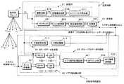
本実施例における超音波診断装置の構成につき図1乃至図7を用いて説明する。尚、図1は、超音波診断装置の全体構成を示すブロック図であり、図2は、この超音波診断装置が備えた送受信部及び受信信号処理部のブロック図である。(Device configuration)
The configuration of the ultrasonic diagnostic apparatus according to this embodiment will be described with reference to FIGS. FIG. 1 is a block diagram showing the overall configuration of the ultrasonic diagnostic apparatus, and FIG. 2 is a block diagram of a transmission / reception unit and a received signal processing unit included in the ultrasonic diagnostic apparatus.
図1に示す本実施例の超音波診断装置100は、被検体の2次元あるいは3次元領域に対して超音波パルス(送信超音波)を送信し前記被検体から得られた超音波反射波(受信超音波)を電気信号(受信信号)に変換する複数の振動素子を備えた超音波プローブ3と、被検体の所定方向に対して超音波パルスを送信するための駆動信号を超音波プローブ3の前記振動素子に供給しこれらの振動素子から得られた複数チャンネルの受信信号を整相加算する送受信部2と、整相加算後の受信信号を信号処理してBモードデータ及びカラードプラデータを生成する受信信号処理部4と、被検体に対する2次元走査によって得られたBモードデータ及びカラードプラデータを超音波の送受信方向に対応させて配列し診断用の第1の画像データ(過去の画像データ)及び第2の画像データ(最新の画像データ)を生成する画像データ生成部5と、当該被検体の広範囲な3次元領域に対する超音波の送受信によって収集されたBモードデータに基づいて広範囲ボリュームデータを生成し、更に、上述の第1の画像データ及び第2の画像データの撮影位置を基準とした当該被検体の狭範囲な3次元領域に対する超音波の送受信によって収集されたBモードデータに基づいて狭範囲ボリュームデータを生成するボリュームデータ生成部6を備えている。 The ultrasonic
又、超音波診断装置100は、当該被検体の広範囲な3次元領域に対しX線CT装置が予め収集したCTボリュームデータとボリュームデータ生成部6が前記3次元領域に対して生成した広範囲ボリュームデータとを夫々の位置情報に基づいて合成しボディマーク用ボリュームデータを生成するボリュームデータ合成部7と、ボディマーク用ボリュームデータに基づいてボディマークを生成するボディマーク生成部8と、ボディマーク用ボリュームデータと狭範囲ボリュームデータとの演算処理により第1の画像データ及び第2の画像データの撮影位置を検出する撮影位置検出部9と、各種超音波プローブの形状データが予め保管されているプローブ形状データ保管部10と、後述の入力部15から供給されるプローブ識別情報に基づき形状データ保管部10に保管された複数の形状データの中から超音波プローブ3に好適な形状データを選択し、この形状データに基づいて第1の画像データ及び第2の画像データの撮影位置を示す第1のプローブマーク及び第2のプローブマークを生成するプローブマーク生成部11と、ボディマークに第1のプローブマーク及び第2のプローブマークを付加して検査支援データを生成する検査支援データ生成部12を備え、更に、第1の画像データをその付帯情報である検査支援データと共に保存する画像データ記憶部13と、第1の画像データ及び第2の画像データを検査支援データと共に表示する表示部14と、被検体情報の入力、ボリュームデータ収集条件の設定、画像データ生成条件の設定、プローブ識別情報の入力、各種コマンド信号の入力等を行なう入力部15と、上述の各ユニットを統括的に制御するシステム制御部16を備えている。 The ultrasonic
以下に、本実施例の超音波診断装置100が備えた上述の各ユニットにつき更に詳しく説明する。 Hereinafter, each of the above-described units included in the ultrasonic
超音波プローブ3は、2次元配列された図示しないNx個の振動素子をその先端部に有し、これら振動素子の各々は、Nxチャンネルの多芯ケーブルを介して送受信部2の入出力端子に接続されている。振動素子は電気音響変換素子であり、送信時には電気パルス(駆動信号)を超音波パルス(送信超音波)に変換し、又、受信時には超音波反射波(受信超音波)を電気的な受信信号に変換する機能を有している。尚、本実施例では、Nx個の振動素子が2次元配列されているセクタ走査用の超音波プローブ3を用いた場合について述べるが、リニア走査、コンベックス走査、ラジアル走査等に対応した超音波プローブであっても構わない。 The
次に、図2に示す送受信部2は、当該被検体に対して送信超音波を放射するための駆動信号を超音波プローブ3に設けられたNx個の振動素子に供給する送信部21と、前記振動素子から得られたNxチャンネルの受信信号に対して整相加算を行なう受信部22を備えている。 Next, the transmission /
送信部21は、レートパルス発生器211と、送信遅延回路212と、駆動回路213を備え、レートパルス発生器211は、送信超音波の繰り返し周期を決定するレートパルスを、システム制御部16から供給される基準信号を分周することによって生成する。送信遅延回路212は、Nxチャンネルの独立な遅延回路から構成され、送信において細いビーム幅を得るために所定の深さに送信超音波を集束するための遅延時間(集束用遅延時間)と所定の送受信方向(θp、φq)に送信超音波を放射するための遅延時間(偏向用遅延時間)を前記レートパルスに与える。そして、Nxチャンネルの独立な駆動回路213は、超音波プローブ3に内蔵されたNx個の振動素子を駆動するための駆動パルスを前記レートパルスに基づいて生成する。 The
一方、受信部22は、Nxチャンネルから構成されるプリアンプ221、A/D変換器222及び受信遅延回路223と、加算器224を備えている。プリアンプ221は、上述の振動素子によって電気信号に変換された微小な受信信号を増幅して十分なS/Nを確保し、このプリアンプ221において増幅されたNxチャンネルの受信信号はA/D変換器222にてデジタル信号に変換される。受信遅延回路223は、所定の深さからの超音波反射波を集束するための集束用遅延時間と所定の送受信方向(θp、φq)に対して強い受信指向性を設定するための偏向用遅延時間を、A/D変換器222から出力されるNxチャンネルの受信信号の各々に与え、加算器224は、これら受信遅延回路223から供給される受信信号を加算合成する。即ち、受信遅延回路223と加算器224により、所定方向から得られた受信信号は整相加算(位相合わせして加算)される。 On the other hand, the receiving
図3は、超音波プローブ3の中心軸をZo軸とした直交座標(Xo−Yo−Zo)に対する超音波の送受信方向(θp、φq)の関係を示す。例えば、Nx個の振動素子はXo軸方向及びYo軸方向に2次元配列され、θp及びφqは、Xo−Zo平面及びYo−Zo平面に投影された送受信方向を示している。 FIG. 3 shows the relationship of the ultrasonic wave transmission / reception direction (θp, φq) with respect to the orthogonal coordinates (Xo-Yo-Zo) with the central axis of the
次に、図2の受信信号処理部4は、受信部22の加算器224から出力された受信信号を信号処理してBモードデータを生成するBモードデータ生成部41と、前記受信信号を直交位相検波してドプラ信号を検出するドプラ信号検出部42と、検出されたドプラ信号に基づいて主要血管内の血流情報を反映したカラードプラデータを生成するカラードプラデータ生成部43を備えている。Bモードデータ生成部41は、受信部22の加算器224から供給される整相加算後の受信信号を包絡線検波する包絡線検波器411と、包絡線検波後の受信信号を対数変換する対数変換器412を備えている。但し、包絡線検波器411と対数変換器412は順序を入れ替えて構成してもよい。 Next, the reception
一方、ドプラ信号検出部42は、π/2移相器421、ミキサ422−1及び422−2、LPF(低域通過フィルタ)423−1及び423−2を備え、受信部22の加算器224から供給される受信信号を直交位相検波してドプラ信号を検出する。 On the other hand, the Doppler signal detection unit 42 includes a π / 2
カラードプラデータ生成部43は、ドプラ信号検出部42によって検出されたドプラ信号を一旦保存するドプラ信号記憶回路431と、このドプラ信号に含まれる生体組織等の移動に起因したドプラ信号成分(クラッタ成分)を排除し血流に起因したドプラ信号成分を抽出するMTIフィルタ432と、抽出されたドプラ信号成分に対して自己相関演算を行ない、この演算結果に基づいて得られた特性値(例えば、血流の平均速度値、分散値、パワー値)を用いてカラードプラデータを生成する自己相関演算器433を備えている。 The color Doppler data generation unit 43 includes a Doppler
図1へ戻って、画像データ生成部5は、図示しないBモードデータ記憶部及びカラードプラデータ記憶部とデータ処理部を備えている。前記Bモードデータ記憶部及び前記カラードプラデータ記憶部には、当該被検体の2次元領域に対する超音波の送受信によって収集されたBモードデータ及びカラードプラデータが超音波の送受信方向を付帯情報として保存される。一方、前記データ処理部は、前記Bモードデータ記憶部から読み出したBモードデータを送受信方向に対応させて配列することにより2次元Bモードデータを形成し、同様にして、前記カラードプラデータ記憶部から読み出したカラードプラデータに基づいて2次元カラードプラデータを形成する。そして、2次元Bモードデータ及び2次元カラードプラデータに対してフィルタリング処理や合成処理等を行なって治療対象部位の経過観察に使用する第1の画像データ(過去の画像データ)及び第2の画像データ(最新の画像データ)を生成する。 Returning to FIG. 1, the image
次に、ボリュームデータ生成部6は、図示しないBモードデータ記憶部と補間処理部を備えている。前記Bモードデータ記憶部には、当該被検体の広範囲な3次元領域に対する超音波の送受信によって収集されたBモードデータと前記被検体における第1の画像データ及び第2の画像データの撮影位置を基準とした狭範囲な3次元領域に対する超音波の送受信によって収集されたBモードデータが超音波の送受信方向を付帯情報として保存される。 Next, the volume
一方、前記補間処理部は、前記Bモードデータ記憶部から読み出したBモードデータを送受信方向に対応させて配列することにより3次元Bモードデータを形成し、更に、この3次元Bモードデータを構成する不等間隔のボクセルを補間処理して等方的なボクセルで構成される広範囲ボリュームデータ及び狭範囲ボリュームデータを生成する。 On the other hand, the interpolation processing unit forms the three-dimensional B-mode data by arranging the B-mode data read from the B-mode data storage unit in correspondence with the transmission / reception direction, and further configures the three-dimensional B-mode data. Wide range volume data and narrow range volume data composed of isotropic voxels are generated by interpolating the unequally spaced voxels.
ボリュームデータ合成部7は、CTボリュームデータ記憶部と演算部とボディマーク用ボリュームデータ記憶部(何れも図示せず)を備え、前記CTボリュームデータ記憶部には、当該被検体の広範囲な3次元領域に対してX線CT装置が収集したCTボリュームデータが予め保管されている。そして、前記演算部は、前記CTボリュームデータ記憶部から読み出したCTボリュームデータと前記被検体の3次元領域に対する超音波の3次元走査に基づいてボリュームデータ生成部6が生成した広範囲ボリュームデータとを夫々の位置情報に基づいて合成してボディマーク用ボリュームデータを生成する。そして、得られたボディマーク用ボリュームデータを前記ボディマーク用ボリュームデータ記憶部に保存する。尚、上述のCTボリュームデータ及び広範囲ボリュームデータに対し、例えば、相互情報量(Mutual Information)を用いた方法を適用することにより正確な位置合わせが可能となるが、本実施例では、CTボリュームデータと広範囲ボリュームデータとの相対的な位置関係が常に一定であるならば高い位置合わせ精度は必ずしも必要としない。 The volume
次に、ボディマーク生成部8は、図示しないフィルタリング処理部を備え、ボリュームデータ合成部7から供給されるボディマーク用ボリュームデータをフィルタリング処理して当該被検体の体表輪郭データを抽出し、得られた体表輪郭データに基づいてボディマークを生成する。 Next, the body mark generation unit 8 includes a filtering processing unit (not shown), filters the body mark volume data supplied from the volume
一方、撮影位置検出部9は、ボリュームデータ合成部7の前記ボディマーク用ボリュームデータ記憶部から供給されるボディマーク用ボリュームデータの広範囲ボリュームデータとボリュームデータ生成部6から供給される狭範囲ボリュームデータとの演算処理により第1の画像データ及び第2の画像データの撮影位置を検出する。尚、ここでは、2つのボリュームデータに相互相関法を適用して撮影位置を検出する方法について述べるが、これに限定されるものではなく、例えば、エントロピー法等の他の方法を適用してもよい。 On the other hand, the shooting position detection unit 9 includes wide-range volume data of body mark volume data supplied from the body mark volume data storage unit of the volume
相互相関法を適用した撮影位置の検出方法を模式的に示す図4において、第1の画像データあるいは第2の画像データの撮影位置に超音波プローブ3を配置して収集した狭範囲ボリュームデータVd1の3次元関心領域Ro3(p、q、r)(p=1〜P,q=1〜Q、r=1〜R)における信号強度(輝度)をA(p、q、r)、ボディマーク用ボリュームデータを構成する広範囲ボリュームデータVdmにおけるボクセル(p、q、r)の信号強度をB(p、q、r)とすれば、第1の画像データあるいは第2の画像データの撮影位置を検出するための評価関数βAB(j、k、s)は、次式(1)によって示される。
そして、狭範囲ボリュームデータVd1の3次元関心領域Ro3における関心領域データを広範囲ボリュームデータVdmに対しp方向、q方向及びr方向に逐次移動させながら上式(1)の評価関数γAB(j、k、s)を算出し、j=jx、k=kx及びs=sxにおいてγAB(j、k、s)がピーク値を有した場合、第1の画像データあるいは第2の画像データの撮影位置はボディマークの座標(jx、kx、sx)に対応しているものとして検出される。但し、上式(1)におけるNは、狭範囲ボリュームデータVd1の3次元関心領域Ro3におけるp方向のボクセル数P、q方向のボクセル数Q及びr方向のボクセル数Rの積を示している。Then, while sequentially moving the region-of-interest data in the three-dimensional region of interest Ro3 of the narrow range volume data Vd1 in the p direction, q direction, and r direction with respect to the wide range volume data Vdm, the evaluation function γAB (j, k, s) is calculated, and when γAB (j, k, s) has a peak value at j = jx, k = kx, and s = sx, the first image data or the second image data is captured. The position is detected as corresponding to the coordinates (jx, kx, sx) of the body mark. However, N in the above formula (1) indicates the product of the number P of voxels in the p direction, the number of voxels Q in the q direction, and the number of voxels R in the r direction in the three-dimensional region of interest Ro3 of the narrow range volume data Vd1.
次に、プローブ形状データ保管部10には、セクタ走査用、リニア走査用、コンベックス走査用等の各種超音波プローブの形状データ(例えば、ワイヤフレームデータ)が、プローブ識別情報に対応させて予め保管されている。そして、プローブマーク生成部11は、図示しないプローブ形状データ選択部及びデータ方向変換処理部を備え、前記プローブ形状データ選択部は、入力部15からシステム制御部16を介して供給される超音波プローブ3のプローブ識別情報に基づきプローブ形状データ保管部10に予め保管されている複数の形状データの中から超音波プローブ3に好適な形状データを選択する。一方、前記方向変換処理部は、撮影位置検出部9から供給される撮影位置情報に基づき前記プローブ形状データ選択部が選択した形状データに対して方向変換(回転)処理を行なって第1の画像データ及び第2の画像データの撮影位置を示す第1のプローブマーク及び第2のプローブマークを生成する。 Next, in the probe shape
次に、検査支援データ生成部12は、撮影位置検出部9から供給される撮影位置情報に基づき、ボディマーク生成部8から供給されるボディマークにプローブマーク生成部11から供給される第1のプローブマーク及び第2のプローブマークを配置する。更に、前記撮影位置情報に基づき、画像データ生成部5から供給される第1の画像データ及び第2の画像データあるいは画像データ記憶部13から供給される第1の画像データに対して縮小変換や方向変換等の変換処理を行ない、変換処理後の第1の画像データ及び第2の画像データを上述の第1のプローブマーク及び第2のプローブマークに付加して検査支援データを生成する。 Next, based on the imaging position information supplied from the imaging position detection unit 9, the inspection support
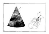
図5は、検査支援データ生成部12によって生成される検査支援データの具体例を示したものであり、この検査支援データは、ボディマーク生成部8がボリュームデータ合成部7から供給されるボディマーク用ボリュームデータの体表面輪郭データを抽出して生成したボディマークBmにプローブマーク生成部11が生成した第1のプローブマークPa及び第2のプローブマークPbが重畳されている。 FIG. 5 shows a specific example of the inspection support data generated by the inspection support
そして、第1のプローブマークPa及び第2のプローブマークPbの各々は、撮影位置検出部9によって検出される第1の画像データ及び第2の画像データの撮影位置に対応したボディマークBm上の位置に夫々配置され、これらのプローブマークの先端部には、画像データ生成部5や画像データ記憶部13から供給され検査支援データ生成部12において縮小変換や方向変換等の変換処理がなされた第1の画像データIax及び第2の画像データIbxが付加されている。尚、第1のプローブマークPa及び第2のプローブマークPbに付加される第1の画像データIax及び第2の画像データIbxは、画像データ生成部5が生成する第1の画像データ及び第2の画像データのサムネールであってもよく、又、画像データの収集範囲のみを示すものであっても構わない。更に、第1のプローブマークPa及び第2のプローブマークPbのみをボディマークBmに重畳してもよい。 Each of the first probe mark Pa and the second probe mark Pb is on the body mark Bm corresponding to the shooting position of the first image data and the second image data detected by the shooting position detector 9. The probe marks are arranged at respective positions, and the tip portions of these probe marks are supplied from the image
図1へ戻って、画像データ記憶部13は、画像データ生成部5において生成された第1の画像データとこの第1の画像データの収集時に検査支援データ生成部12において生成された検査支援データを保存する。この場合の検査支援データは、ボディマーク生成部8において生成されたボディマークBmと第1の画像データの撮影位置を示す第1のプローブマークPaと変換処理された第1の画像データIaxとの合成によって生成されている(図5参照)。 Returning to FIG. 1, the image
次に、表示部14は、第1の画像データ及び第2の画像データの比較表示と第1の画像データ及び第2の画像データの撮影位置を示す第1のプローブマーク及び第2のプローブマークをボディマークに付加して生成された検査支援データを表示する機能を有し、図示しない表示データ生成回路と変換回路とモニタを備えている。 Next, the
前記表示データ生成回路は、画像データ生成部5から供給される第1の画像データあるいは画像データ記憶部13から供給される第1の画像データと画像データ生成部5から供給される第2の画像データに検査支援データ生成部12が生成した検査支援データや被検体情報等の付帯情報を付加して表示データを生成し、前記変換回路は、前記表示データに対しD/A変換とテレビフォーマット変換を行なって前記モニタに表示する。 The display data generation circuit includes first image data supplied from the image
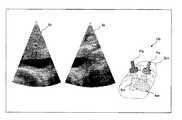
次に、第1の画像データの収集時に生成される表示用データと第2の画像データの収集時に生成される表示用データの具体例につき図6及び図7を用いて説明する。 Next, specific examples of the display data generated when collecting the first image data and the display data generated when collecting the second image data will be described with reference to FIGS.
図6に示した第1の画像データの収集時に生成される表示用データの左領域には、診断対象部位の撮影に好適な位置に超音波プローブ3を配置して収集した第1の画像データIaが配置され、前記表示用データの右領域には、このときの撮影位置(即ち、超音波プローブ3の被検体に対する位置情報)を示す第1のプローブマークPaと変換処理後の第1の画像データIaxとがボディマークBmに付加して生成された検査支援データDaが配置される。そして、表示用データの左領域に示された第1の画像データIaは、動画像として表示部14にリアルタイム表示される。 In the left region of the display data generated when the first image data shown in FIG. 6 is collected, the first image data collected by arranging the
一方、図7に示した第2の画像データの収集時に生成される表示データの左領域には、画像データ記憶部13から読み出された上述の第1の画像データIaと超音波プローブ3を当該被検体の体表面上で移動させながら収集した第2の画像データIbが並列配置され、前記表示データの左領域には、第1の画像データIaの撮影位置を示す第1のプローブマークPa及び変換処理後の第1の画像データIaxと第2の画像データIbの撮影位置を示す第2のプローブマークPb及び変換処理後の第2の画像データIbxをボディマークBmに付加して生成された検査支援データDbが配置される。この場合、第1のプローブマークPaが示す撮影位置にて収集された第1の画像データIaは静止画像として表示部14に表示され、第2のプローブマークPbが示す撮影位置にて収集された第2の画像データIbは動画像として表示部14にリアルタイム表示される。 On the other hand, in the left area of the display data generated when the second image data shown in FIG. 7 is collected, the first image data Ia and the
そして、操作者は、表示部14において第1の画像データ及び第2の画像データと共に表示される検査支援データDbを観察しながら当該被検体の体表面に沿って超音波プローブ3を移動させ、この移動に伴なって検査支援データDbのボディマークBm上を移動する第2のプローブマークPbが第1のプローブマークに一致した時点で超音波プローブ3の移動を停止させることにより第1の画像データと同一の撮影位置における第2の画像データを収集することが可能となる。 Then, the operator moves the
次に、図1の入力部15は、表示パネルやキーボード、各種スイッチ、選択ボタン、マウス等の入力デバイスを備えたインターラクティブなインターフェースであり、超音波プローブ3の識別情報を入力する識別情報入力部151や検査支援データに対する視線方向を設定する視線方向設定部152を備えている。更に、被検体情報の入力、ボリュームデータ収集条件の設定、画像データ生成条件の設定、画像データ及び検査支援データに対する表示条件の設定、各種コマンド信号の入力等が入力部15に設けられた上述の入力デバイスを用いて行なわれる。 Next, the
システム制御部16は、図示しないCPUと記憶回路を備え、前記記憶回路には入力部15の各ユニットにて入力/設定された上述の各種情報が保存される。そして、前記CPUは、上述の入力情報及び設定情報に基づいて超音波診断装置100の各ユニットを制御し検査支援データの生成と表示を行なう。そして、この検査支援データに基づいて同一撮影位置における第1の画像データと第2の画像データを収集する。 The
(検査支援データの生成手順)
次に、本実施例における検査支援データの生成手順につき図8のフローチャートを用いて説明する。(Procedure for generating inspection support data)
Next, a procedure for generating inspection support data in the present embodiment will be described with reference to the flowchart of FIG.
検査支援データの生成に先立ち超音波診断装置100の操作者は、入力部15において被検体情報の入力、ボリュームデータ収集条件の設定、画像データ生成条件の設定、画像データ及び検査支援データに対する表示条件の設定、更には、入力部15の識別情報入力部151による超音波プローブ3の識別情報の入力、視線方向設定部152による検査支援データの視線方向の設定等を行なう(図8のステップS1)。 Prior to the generation of examination support data, the operator of the ultrasonic
上述の初期設定が終了したならば、操作者は、入力部15にて広範囲ボリュームデータの収集開始コマンドを入力する。このコマンド信号を受信したシステム制御部16は、送受信部2及び受信信号処理部4を制御して当該被検体の広範囲な3次元領域に対して超音波の送受信を行ない、得られた受信信号を処理してBモードデータを生成する。 When the above-described initial setting is completed, the operator inputs a wide-area volume data collection start command through the
一方、ボリュームデータ生成部6は、受信信号処理部4から供給される3次元的なBモードデータを補間処理して広範囲ボリュームデータを生成し、ボリュームデータ合成部7は、ボリュームデータ生成部6から供給される広範囲ボリュームデータと自己のCTボリュームデータ記憶部に予め保管されている当該被検体のCTボリュームデータとを夫々の位置情報に基づいて合成しボディマーク用ボリュームデータを生成する。そして、得られたボディマーク用ボリュームデータを自己のボディマーク用ボリュームデータ記憶部に保存する(図8のステップS2)。 On the other hand, the
次いで、ボディマーク生成部8は、ボリュームデータ合成部7から供給されるボディマーク用ボリュームデータをフィルタリング処理して当該被検体の体表輪郭データを抽出し、得られた体表輪郭データに基づいてボディマークを生成する(図8のステップS3)。 Next, the body mark generation unit 8 extracts the body surface contour data of the subject by filtering the body mark volume data supplied from the volume
ボディマークの生成が終了したならば、操作者は、当該被検体の体表面における好適な位置に超音波プローブ3の先端部を設定し、次いで、入力部15において、第1の画像データ及びこの第1の画像データの撮影位置を示す検査支援データの生成開始コマンドを入力する(図8のステップS4)。 When the generation of the body mark is completed, the operator sets the distal end portion of the
そして、このコマンド信号を受信したシステム制御部16は、上述と同様に送受信部2及び受信信号処理部4を制御し前記撮影位置を基準とした2次元走査によってBモードデータ及びカラードプラデータを生成する。一方、画像データ生成部5は、受信信号処理部4から供給されるBモードデータ及びカラードプラデータを送受信方向に対応させて配列することにより2次元Bモードデータ及び2次元カラードプラデータを形成し、これらのデータに対してフィルタリング処理や合成処理等を行なって生成した第1の画像データを表示部14のモニタに表示する(図8のステップS5)。 Upon receiving this command signal, the
次に、前記撮影位置における超音波の2次元走査が所定回数あるいは所定期間行なわれたならば、システム制御部16は、送受信部2及び受信信号処理部4を再度制御して前記撮影位置を基準とした当該被検体の狭範囲な3次元領域に対し超音波の送受信を行なってBモードデータを生成し、ボリュームデータ生成部6は、このとき受信信号処理部4から供給される3次元的なBモードデータを補間処理して狭範囲ボリュームデータを生成する(図8のステップS6)。 Next, when the two-dimensional scanning of the ultrasonic wave at the imaging position is performed a predetermined number of times or for a predetermined period, the
そして、撮影位置検出部9は、ボリュームデータ合成部7の前記ボディマーク用ボリュームデータ記憶部から供給されるボディマーク用ボリュームデータの広範囲ボリュームデータとボリュームデータ生成部6から供給される狭範囲ボリュームデータとの演算処理により第1の画像データの撮影位置を検出する(図8のステップS7)。 Then, the photographing position detection unit 9 includes the wide range volume data of the body mark volume data supplied from the body mark volume data storage unit of the volume
一方、プローブマーク生成部11は、入力部15の識別情報入力部151からシステム制御部16を介して供給される超音波プローブ3のプローブ識別情報に基づき、プローブ形状データ保管部10に予め保管されている複数の形状データの中から超音波プローブ3に好適な形状データを選択する。更に、撮影位置検出部9から供給される撮影位置情報に基づいて前記形状データを方向変換処理し、第1の画像データの撮影位置を示す第1のプローブマークを生成する(図8のステップS8)。 On the other hand, the probe mark generation unit 11 is stored in advance in the probe shape
次に、検査支援データ生成部12は、撮影位置検出部9から供給される撮影位置情報に基づき、ボディマーク生成部8から供給されるボディマークにプローブマーク生成部11から供給される第1のプローブマークを付加する。更に、画像データ生成部5から供給される第1の画像データを前記撮影位置情報に基づいて変換処理し、変換処理後の第1の画像データを上述の第1のプローブマークに付加して検査支援データを生成する。そして、生成した検査支援データを第1の画像データと共に表示部14のモニタに表示する。(図6参照)(図8のステップS9)。 Next, based on the imaging position information supplied from the imaging position detection unit 9, the inspection support
表示部14において検査支援データと共に表示される第1の画像データを観察した操作者は、診断対象部位に対し好適な撮影位置が設定されているか否かを判定し、撮影位置が好ましくない場合には、超音波プローブ3の位置を更新しながら上述のステップS4乃至S9を繰り返す(図8のステップS4乃至S9)。 The operator who has observed the first image data displayed together with the examination support data on the
一方、診断対象部位に対し好適な撮影位置が設定されていると判定した場合には、画像データ生成部5において生成される第1の画像データとこの第1の画像データの収集時に検査支援データ生成部12において生成される(即ち、第1の画像データの撮影位置が第1のプローブマークとして示されている)検査支援データを画像データ記憶部13に保存する(図8のステップS10)。 On the other hand, if it is determined that a suitable imaging position is set for the diagnosis target region, the first image data generated by the image
次に、当該被検体の診断対象部位に対する経過観察に際し、操作者は、入力部15において第1の画像データ(過去の画像データ)と第2の画像データ(最新の画像データ)との比較表示を行なうためのコマンド信号を入力し、このコマンド信号を受信したシステム制御部16は、画像データ記憶部13において予め保管されている第1の画像データ(過去の画像データ)とこの第1の画像データの撮影位置が第1のプローブマークとして示された検査支援データを読み出して表示部14に表示する(図8のステップS11)。 Next, in the follow-up observation of the diagnosis target region of the subject, the operator compares and displays the first image data (past image data) and the second image data (latest image data) in the
次に、操作者は、当該被検体の体表面に超音波プローブ3の先端部を設定し(図8のステップS12)、送受信部2及び受信信号処理部4は、超音波プローブ3の設定位置に基づいた第2の画像データの撮影位置を基準とする2次元走査によってBモードデータとカラードプラデータを生成する。一方、画像データ生成部5は、受信信号処理部4から供給されるBモードデータ及びカラードプラデータを送受信方向に対応させて配列することにより2次元Bモードデータ及び2次元カラードプラデータを形成し、これらのデータに対してフィルタリング処理や合成処理等を行なって第2の画像データを生成する(図8のステップS13)。このとき得られた第2の画像データは、必要に応じて第1の画像データと共に表示部14のモニタに表示される。 Next, the operator sets the tip of the
次に、送受信部2及び受信信号処理部4は、第2の画像データの撮影位置を基準とする当該被検体の狭範囲な3次元領域に対し超音波の送受信を行なってBモードデータを生成し、ボリュームデータ生成部6は、このとき受信信号処理部4から供給される3次元的なBモードデータを補間処理して狭範囲ボリュームデータを生成する(図8のステップS14)。そして、撮影位置検出部9は、ボリュームデータ合成部7の前記ボディマーク用ボリュームデータ記憶部から供給されるボディマーク用ボリュームデータの広範囲ボリュームデータとボリュームデータ生成部6から供給される狭範囲ボリュームデータとの演算処理により第2の画像データの撮影位置を検出する(図8のステップS15)。 Next, the transmission /
一方、プローブマーク生成部11は、入力部15の識別情報入力部151からシステム制御部16を介して供給される超音波プローブ3のプローブ識別情報に基づき、プローブ形状データ保管部10に予め保管されている複数の形状データの中から超音波プローブ3に好適な形状データを選択する。更に、撮影位置検出部9から供給される撮影位置情報に基づいて前記形状データを方向変換処理し第2の画像データの撮影位置を示す第2のプローブマークを生成する(図8のステップS16)。 On the other hand, the probe mark generation unit 11 is stored in advance in the probe shape
次に、検査支援データ生成部12は、上述のステップS11にて画像データ記憶部13から読み出した検査支援データにプローブマーク生成部11から供給された第2のプローブマークと変換処理した第2の画像データを追加して検査支援データを更新する(図8のステップS17)。そして、表示部14は、画像データ記憶部13から読み出した第1の画像データ、画像データ生成部5から供給された第2の画像データ及び検査支援データ生成部12から供給された更新後の検査支援データに基づいて生成した表示データを自己のモニタに表示する(図7参照)(図8のステップS18)。 Next, the inspection support
表示部14に表示された表示データの検査支援データを観察した操作者は、ボディマーク上の第2のプローブマークが第1のプローブマークに接近する方向に超音波プローブ3を移動させる。このとき、システム制御部16は、超音波診断装置100の各ユニットを制御して上述のステップS12乃至S18を繰り返す(図8のステップS12乃至S18)。 An operator observing the inspection support data of the display data displayed on the
そして、第1のプローブマークと第2のプローブマークが略一致あるいは接近したならば、このとき得られた第2の画像データとこの第2の画像データの撮影位置が第2のプローブマークとして示された検査支援データは画像データ記憶部13に保存される。そして、上述の検査支援データを付帯情報として保存された第2の画像データは、当該診断対象部位に対する次回の経過観察において第1の画像データとして使用される。 If the first probe mark and the second probe mark substantially coincide with each other or approach each other, the second image data obtained at this time and the shooting position of the second image data are indicated as the second probe mark. The inspection support data thus stored is stored in the image
尚、超音波プローブ3の移動に伴なって第1のプローブマークと第2のプローブマークが所定の許容範囲内で一致した場合、その情報を操作者に報知する手段を表示部14あるいは入力部15に設けることにより第1の画像データの撮影位置と第2の画像データの撮影位置を容易かつ正確に一致させることができる。例えば、検査支援データにおける第1のプローブマーク及び第2のプローブマークの少なくとも何れかを強調表示(フラッシュ表示や高輝度表示等)することによって第1の画像データの撮影位置と第2の画像データの撮影位置との一致を報知してもよい。 When the first probe mark and the second probe mark coincide with each other within a predetermined allowable range as the
以上述べた本発明の実施例によれば、当該被検体の広範囲な3次元領域から収集されたボリュームデータと撮影位置を基準とした狭範囲な3次元領域から収集されたボリュームデータの演算処理により画像データの撮影位置を検出することができるため、超音波プローブの位置や方向の検出を目的とした複雑な機構を有する位置検出手段を用いることなく前記被検体の同一撮影位置における過去の画像データ(第1の画像データ)と最新の画像データ(第2の画像データ)を精度よく収集することが可能となる。 According to the embodiment of the present invention described above, the volume data collected from a wide range of 3D regions of the subject and the volume data collected from a narrow range of 3D regions based on the imaging position are used. Since the imaging position of the image data can be detected, past image data at the same imaging position of the subject without using a position detection means having a complicated mechanism for detecting the position and direction of the ultrasonic probe (First image data) and the latest image data (second image data) can be collected with high accuracy.
又、本実施例によれば、ボデーマーク上に配置された第1の画像データの撮影位置を示す第1のプローブマークと第2の画像データの撮影位置を示す第2のプローブマークが一致するように超音波プローブを移動させることにより、同一撮影位置における第1の画像データと第2の画像データを容易かつ短時間で収集することができる。 According to this embodiment, the first probe mark indicating the shooting position of the first image data arranged on the body mark matches the second probe mark indicating the shooting position of the second image data. By moving the ultrasonic probe as described above, the first image data and the second image data at the same photographing position can be collected easily and in a short time.
更に、超音波プローブの移動によって第1のプローブマークと第2のプローブマークが所定の許容範囲内で一致した場合、その一致情報を操作者に報知することにより第1の画像データの撮影位置と第2の画像データの撮影位置を容易かつ正確に一致させることができる。 Further, when the first probe mark and the second probe mark coincide with each other within a predetermined allowable range due to the movement of the ultrasonic probe, the coincidence information is notified to the operator, thereby obtaining the photographing position of the first image data. The shooting positions of the second image data can be easily and accurately matched.
以上の理由により、当該被検体の経過観察等における検査効率や診断精度が向上するのみならず操作者の負担が大幅に軽減される。 For the above reasons, not only the examination efficiency and diagnostic accuracy in the follow-up observation of the subject is improved, but also the burden on the operator is greatly reduced.
更に、上述の実施例では、画像データの生成に使用した超音波プローブによって収集される広範囲ボリュームデータ及び狭範囲ボリュームデータに基づいて撮影位置の検出を行なっているため、従来のような複雑かつ大規模な構成を有する位置情報検出手段を用いる必要が無く、従って、操作者による医療行為が阻害されることもない。 Furthermore, in the above-described embodiment, since the photographing position is detected based on the wide range volume data and the narrow range volume data collected by the ultrasonic probe used for generating the image data, the conventional complicated and large size is required. There is no need to use position information detection means having a large-scale configuration, and therefore, medical practice by the operator is not hindered.
以上、本発明の実施例について述べてきたが、本発明は、上述の実施例に限定されるものではなく、変形して実施することが可能である。例えば、上述の実施例では、X線CT装置によって収集されたCTボリュームデータと超音波の3次元走査によって収集された広範囲ボリュームデータを合成してボディマーク用ボリュームデータを生成する場合について述べたが、MRI装置等の他の画像診断装置によって収集されたボリュームデータと前記広範囲ボリュームデータを合成してボディマーク用ボリュームデータを生成してもよい。又、広範囲ボリュームデータのみ、あるいは広範囲ボリュームデータと被検体をモデル化した従来のボディマークを合成してボディマーク用ボリュームデータを生成してもよい。 As mentioned above, although the Example of this invention has been described, this invention is not limited to the above-mentioned Example, It can change and implement. For example, in the above-described embodiment, the case has been described in which body volume data is generated by synthesizing CT volume data collected by an X-ray CT apparatus and wide-range volume data collected by ultrasonic three-dimensional scanning. Alternatively, volume data for body marks may be generated by combining the volume data collected by another diagnostic imaging apparatus such as an MRI apparatus and the wide-range volume data. Alternatively, body mark volume data may be generated by combining only a wide range of volume data or a conventional body mark that models a wide range of volume data and a subject.
又、診断対象部位の経過観察に用いられる過去の画像データ(第1の画像データ)及び最新の画像データ(第2の画像データ)は、当該被検体に対する超音波の2次元走査によって収集される2次元画像データである場合について述べたが、3次元走査によって収集されるボリュームデータに基づいた3次元画像データであってもよく、前記ボリュームデータの所定断面に対して形成されるMPR(Multi Planar Reconstruction)画像データであっても構わない。又、この場合の3次元画像データやMPR画像データは、画像データの撮影位置において収集される狭範囲ボリュームデータに基づいて生成されても構わない。 In addition, past image data (first image data) and latest image data (second image data) used for the follow-up of the diagnosis target region are collected by two-dimensional scanning of the ultrasonic wave on the subject. Although the case of two-dimensional image data has been described, it may be three-dimensional image data based on volume data collected by three-dimensional scanning, and MPR (Multi Planar) formed for a predetermined cross section of the volume data. Reconstruction) image data may be used. In this case, the three-dimensional image data and the MPR image data may be generated based on the narrow range volume data collected at the image data shooting position.
更に、上述の検査支援データにおける第1のプローブマーク及び第2のプローブマークは、超音波プローブ3に好適なプローブ形状データを用いて生成する場合について述べたが、ボックス等の簡単な図形や矢印等のラインを用いて生成してもよい。又、異なる超音波プローブを用いて第1の画像データの収集と第2の画像データの収集、あるいは、広範囲ボリュームデータの収集と狭範囲ボリュームデータの収集を行なってもよい。 Furthermore, although the case where the first probe mark and the second probe mark in the above-described inspection support data are generated using probe shape data suitable for the
一方、上述の実施例では、相互相関法の適用によって第1の画像データ及び第2の画像データの撮影位置を検出する方法について述べたが、広範囲ボリュームデータと狭範囲ボリュームデータの差分値を求め、この差分値の絶対値和あるいは2乗和が最小となる移動方向及び移動量に基づいて前記撮影位置を検出する方法(ここでは、差分和最小法と呼ぶ。)やエントロピー法等の他の方法を適用してもよい。 On the other hand, in the above-described embodiment, the method of detecting the shooting positions of the first image data and the second image data by applying the cross-correlation method has been described, but the difference value between the wide-range volume data and the narrow-range volume data is obtained. Other methods such as a method of detecting the photographing position based on the moving direction and moving amount at which the sum of absolute values or the sum of squares of the difference values is minimized (hereinafter referred to as a difference sum minimum method), an entropy method, and the like. A method may be applied.
又、検査支援データにおける第1のプローブマーク及び第2のプローブマークに付加される変換処理後の第1の画像データ及び第2の画像データは、画像データ生成部5が生成する第1の画像データ及び第2の画像データのサムネールであってもよく、又、画像データの収集範囲のみを示すものであっても構わない。更に、第1のプローブマーク及び第2のプローブマークのみをボディマークに付加して検査支援データを生成してもよい。 Further, the first image data and the second image data after the conversion process added to the first probe mark and the second probe mark in the inspection support data are the first image generated by the image
更に、上述の実施例では、複数の振動素子が2次元配列された超音波プローブ3を用いて広範囲ボリュームデータ及び狭範囲ボリュームデータを収集する場合について述べたが、振動素子が1次元配列された超音波プローブを機械的に移動させることによって上述のボリュームデータを収集してもよい。 Furthermore, in the above-described embodiment, the case where wide range volume data and narrow range volume data are collected using the
又、第1の画像データを保存する際に、この第1の画像データの撮影位置が第1のプローブマークとして示された検査支援データとボディマーク用ボリュームデータを前記第1の画像データと共に保存する場合について述べたが、検査支援データの替わりに前記撮影位置を基準に収集された狭範囲ボリュームデータを保存してもよい。この場合、第2の画像データの収集時に第2のプローブマークと共に示される第1のプローブマークの位置及び方向は、一旦保存された広範囲ボリュームデータと狭範囲ボリュームデータとの演算処理に基づいて設定される。更に、第1の画像データの収集におけるスライス断面等の画像データ生成条件を第1の画像データの付帯情報として保存してもよい。この方法を適用することにより、同一の画像データ生成条件による第1の画像データと第2の画像データを容易に収集することが可能となり、検査効率が向上すると共に操作者の負担が低減される。 Further, when storing the first image data, the inspection support data in which the photographing position of the first image data is indicated as the first probe mark and the volume data for the body mark are stored together with the first image data. As described above, narrow range volume data collected based on the imaging position may be stored instead of the inspection support data. In this case, the position and direction of the first probe mark shown together with the second probe mark at the time of collecting the second image data are set based on the arithmetic processing of the once-saved wide-range volume data and narrow-range volume data. Is done. Furthermore, image data generation conditions such as slice slices in the collection of the first image data may be stored as incidental information of the first image data. By applying this method, it is possible to easily collect the first image data and the second image data under the same image data generation conditions, thereby improving the inspection efficiency and reducing the burden on the operator. .
更に、ボリュームデータ生成部6は、超音波プローブ3の位置検出に用いる広範囲ボリュームデータ及び狭範囲ボリュームデータを当該被検体の3次元領域から収集されたBモードデータに基づいて生成する場合について述べたが、これらのボリュームデータをカラードプラデータ等の他の超音波データに基づいて生成してもよい。又、狭範囲ボリュームデータの替わりに2次元画像データあるいは3次元画像データを用いて広範囲ボリュームデータとの演算処理を行なうことによりこれら画像データの撮影位置を検出してもよい。 Furthermore, the case where the volume
2…送受信部
21…送信部
22…受信部
3…超音波プローブ
4…受信信号処理部
41…Bモードデータ生成部
42…ドプラ信号検出部
43…カラードプラデータ生成部
5…画像データ生成部
6…ボリュームデータ生成部
7…ボリュームデータ合成部
8…ボディマーク生成部
9…撮影位置検出部
10…プローブ形状データ保管部
11…プローブマーク生成部
12…検査支援データ生成部
13…画像データ記憶部
14…表示部
15…入力部
151…識別情報入力部
152…視線方向設定部
16…システム制御部
100…超音波診断装置2. Transmission /
Claims (11)
Translated fromJapanese前記振動素子を駆動して前記被検体の2次元領域あるいは3次元領域に対して超音波を送受信すると共に前記振動素子によって得られた前記被検体からの反射信号を受信信号として受信する送受信手段と、
前記被検体の2次元領域あるいは3次元領域から得られた前記受信信号に基づいて画像データを生成する画像データ生成手段と、
前記被検体の3次元領域から得られた前記受信信号に基づいて広範囲ボリュームデータ、あるいは、広範囲ボリュームデータと前記画像データの撮影位置を基準とする狭範囲ボリュームデータを生成するボリュームデータ生成手段と、
前記広範囲ボリュームデータと、前記狭範囲ボリュームデータあるいは前記画像データに基づいて前記画像データの撮影位置を検出する撮影位置検出手段と、
前記撮影位置の検出結果に基づいて検査支援データを生成する検査支援データ生成手段と、
前記検査支援データを表示する表示手段とを
備えたことを特徴とする超音波診断装置。An ultrasonic probe having a vibration element for transmitting and receiving ultrasonic waves to and from a subject;
Transmission / reception means for driving the vibration element to transmit / receive ultrasonic waves to / from a two-dimensional region or a three-dimensional region of the subject and to receive a reflection signal from the subject obtained by the vibration element as a reception signal; ,
Image data generating means for generating image data based on the received signal obtained from a two-dimensional region or a three-dimensional region of the subject;
Volume data generation means for generating wide-range volume data based on the received signal obtained from the three-dimensional region of the subject, or narrow-range volume data based on the imaging position of the wide-range volume data and the image data;
A shooting position detecting means for detecting a shooting position of the image data based on the wide range volume data and the narrow range volume data or the image data;
Inspection support data generating means for generating inspection support data based on the detection result of the imaging position;
An ultrasonic diagnostic apparatus comprising: display means for displaying the examination support data.
Priority Applications (1)
| Application Number | Priority Date | Filing Date | Title |
|---|---|---|---|
| JP2007260280AJP2009089736A (en) | 2007-10-03 | 2007-10-03 | Ultrasonic diagnostic equipment |
Applications Claiming Priority (1)
| Application Number | Priority Date | Filing Date | Title |
|---|---|---|---|
| JP2007260280AJP2009089736A (en) | 2007-10-03 | 2007-10-03 | Ultrasonic diagnostic equipment |
Publications (1)
| Publication Number | Publication Date |
|---|---|
| JP2009089736Atrue JP2009089736A (en) | 2009-04-30 |
Family
ID=40662344
Family Applications (1)
| Application Number | Title | Priority Date | Filing Date |
|---|---|---|---|
| JP2007260280AWithdrawnJP2009089736A (en) | 2007-10-03 | 2007-10-03 | Ultrasonic diagnostic equipment |
Country Status (1)
| Country | Link |
|---|---|
| JP (1) | JP2009089736A (en) |
Cited By (17)
| Publication number | Priority date | Publication date | Assignee | Title |
|---|---|---|---|---|
| JP2011045659A (en)* | 2009-08-28 | 2011-03-10 | Toshiba Corp | Ultrasonic diagnostic apparatus, ultrasonic image processor and ultrasonic image processing program |
| JP2011115456A (en)* | 2009-12-04 | 2011-06-16 | Toshiba Corp | Ultrasonic diagnostic apparatus and control program for image data display |
| JP2012055346A (en)* | 2010-09-04 | 2012-03-22 | Waseda Univ | Ultrasonic diagnostic system, robot for ultrasonograph and program |
| WO2012063420A1 (en)* | 2010-11-12 | 2012-05-18 | パナソニック株式会社 | Ultrasound diagnostic apparatus and ultrasound diagnostic system |
| CN102499715A (en)* | 2011-11-23 | 2012-06-20 | 东南大学 | Identical-trajectory ultrasonic image dynamic contrast system and contrast method thereof |
| JP2012135428A (en)* | 2010-12-27 | 2012-07-19 | Konica Minolta Medical & Graphic Inc | Ultrasonic diagnostic system |
| JP2012525919A (en)* | 2009-05-08 | 2012-10-25 | コーニンクレッカ フィリップス エレクトロニクス エヌ ヴィ | Ultrasound planning and guide for implantable medical devices |
| JPWO2011033793A1 (en)* | 2009-09-18 | 2013-02-07 | パナソニック株式会社 | Ultrasonic diagnostic apparatus and diagnostic method using the same |
| JP2013240374A (en)* | 2012-05-18 | 2013-12-05 | Sony Corp | Image processing apparatus and image processing method |
| JP2014014446A (en)* | 2012-07-06 | 2014-01-30 | Toshiba Corp | Ultrasonic diagnostic apparatus, image generating apparatus, and image display apparatus |
| US20140058261A1 (en)* | 2011-05-26 | 2014-02-27 | Toshiba Medical Systems Corporation | Ultrasonic diagnostic apparatus |
| WO2014129179A1 (en)* | 2013-02-20 | 2014-08-28 | 株式会社 東芝 | Ultrasonic diagnostic device and medical image processing device |
| WO2014148428A1 (en)* | 2013-03-18 | 2014-09-25 | 株式会社 東芝 | Ultrasonic diagnostic device |
| JPWO2013035393A1 (en)* | 2011-09-08 | 2015-03-23 | 株式会社日立メディコ | Ultrasonic diagnostic apparatus and ultrasonic image display method |
| JP2016522074A (en)* | 2013-06-28 | 2016-07-28 | コーニンクレッカ フィリップス エヌ ヴェKoninklijke Philips N.V. | Ultrasound acquisition feedback guidance for target view |
| JP2019502445A (en)* | 2015-12-18 | 2019-01-31 | コーニンクレッカ フィリップス エヌ ヴェKoninklijke Philips N.V. | Apparatus and method for characterizing a subject's tissue |
| CN111281424A (en)* | 2018-12-07 | 2020-06-16 | 深圳迈瑞生物医疗电子股份有限公司 | A method for adjusting ultrasonic imaging range and related equipment |
- 2007
- 2007-10-03JPJP2007260280Apatent/JP2009089736A/ennot_activeWithdrawn
Cited By (29)
| Publication number | Priority date | Publication date | Assignee | Title |
|---|---|---|---|---|
| JP2012525919A (en)* | 2009-05-08 | 2012-10-25 | コーニンクレッカ フィリップス エレクトロニクス エヌ ヴィ | Ultrasound planning and guide for implantable medical devices |
| JP2011045659A (en)* | 2009-08-28 | 2011-03-10 | Toshiba Corp | Ultrasonic diagnostic apparatus, ultrasonic image processor and ultrasonic image processing program |
| US8942453B2 (en) | 2009-09-18 | 2015-01-27 | Konica Minolta, Inc. | Ultrasonograph and method of diagnosis using same |
| JPWO2011033793A1 (en)* | 2009-09-18 | 2013-02-07 | パナソニック株式会社 | Ultrasonic diagnostic apparatus and diagnostic method using the same |
| JP2011115456A (en)* | 2009-12-04 | 2011-06-16 | Toshiba Corp | Ultrasonic diagnostic apparatus and control program for image data display |
| JP2012055346A (en)* | 2010-09-04 | 2012-03-22 | Waseda Univ | Ultrasonic diagnostic system, robot for ultrasonograph and program |
| US9498185B2 (en) | 2010-11-12 | 2016-11-22 | Konica Minolta, Inc. | Ultrasound diagnostic apparatus and ultrasound diagnostic system |
| CN102843973A (en)* | 2010-11-12 | 2012-12-26 | 松下电器产业株式会社 | Ultrasound diagnostic apparatus and ultrasound diagnostic system |
| CN102843973B (en)* | 2010-11-12 | 2017-02-08 | 柯尼卡美能达株式会社 | Ultrasonic diagnostic device and ultrasonic diagnostic system |
| WO2012063420A1 (en)* | 2010-11-12 | 2012-05-18 | パナソニック株式会社 | Ultrasound diagnostic apparatus and ultrasound diagnostic system |
| JP2012135428A (en)* | 2010-12-27 | 2012-07-19 | Konica Minolta Medical & Graphic Inc | Ultrasonic diagnostic system |
| US20140058261A1 (en)* | 2011-05-26 | 2014-02-27 | Toshiba Medical Systems Corporation | Ultrasonic diagnostic apparatus |
| EP2754396A4 (en)* | 2011-09-08 | 2015-06-03 | Hitachi Medical Corp | ULTRASONIC DIAGNOSTIC DEVICE AND ULTRASONIC IMAGE DISPLAY METHOD |
| US9480457B2 (en) | 2011-09-08 | 2016-11-01 | Hitachi Medical Corporation | Ultrasound diagnostic device and ultrasound image display method |
| JPWO2013035393A1 (en)* | 2011-09-08 | 2015-03-23 | 株式会社日立メディコ | Ultrasonic diagnostic apparatus and ultrasonic image display method |
| CN102499715A (en)* | 2011-11-23 | 2012-06-20 | 东南大学 | Identical-trajectory ultrasonic image dynamic contrast system and contrast method thereof |
| US10130334B2 (en) | 2012-05-18 | 2018-11-20 | Sony Corporation | Presenting a graphical representation of an ultrasound scanning volume |
| JP2013240374A (en)* | 2012-05-18 | 2013-12-05 | Sony Corp | Image processing apparatus and image processing method |
| JP2014014446A (en)* | 2012-07-06 | 2014-01-30 | Toshiba Corp | Ultrasonic diagnostic apparatus, image generating apparatus, and image display apparatus |
| WO2014129179A1 (en)* | 2013-02-20 | 2014-08-28 | 株式会社 東芝 | Ultrasonic diagnostic device and medical image processing device |
| CN105142528A (en)* | 2013-03-18 | 2015-12-09 | 株式会社东芝 | Ultrasonic diagnostic device |
| WO2014148428A1 (en)* | 2013-03-18 | 2014-09-25 | 株式会社 東芝 | Ultrasonic diagnostic device |
| JP2014180340A (en)* | 2013-03-18 | 2014-09-29 | Toshiba Corp | Ultrasonic diagnostic apparatus |
| US10213185B2 (en) | 2013-03-18 | 2019-02-26 | Toshiba Medical Systems Corporation | Ultrasonic diagnostic apparatus |
| JP2016522074A (en)* | 2013-06-28 | 2016-07-28 | コーニンクレッカ フィリップス エヌ ヴェKoninklijke Philips N.V. | Ultrasound acquisition feedback guidance for target view |
| US10702248B2 (en) | 2013-06-28 | 2020-07-07 | Koninklijke Philips N.V. | Ultrasound acquisition feedback guidance to a target view |
| JP2019502445A (en)* | 2015-12-18 | 2019-01-31 | コーニンクレッカ フィリップス エヌ ヴェKoninklijke Philips N.V. | Apparatus and method for characterizing a subject's tissue |
| US10762631B2 (en) | 2015-12-18 | 2020-09-01 | Koninklijke Philips N.V. | Apparatus and method for characterizing a tissue of a subject |
| CN111281424A (en)* | 2018-12-07 | 2020-06-16 | 深圳迈瑞生物医疗电子股份有限公司 | A method for adjusting ultrasonic imaging range and related equipment |
Similar Documents
| Publication | Publication Date | Title |
|---|---|---|
| JP2009089736A (en) | Ultrasonic diagnostic equipment | |
| JP5495593B2 (en) | Ultrasonic diagnostic apparatus and puncture support control program | |
| JP4920302B2 (en) | Ultrasonic diagnostic apparatus and ultrasonic measurement method | |
| CN101779969B (en) | Ultrasound diagnosis apparatus, medical image display apparatus and medical image displaying method | |
| JP5395538B2 (en) | Ultrasonic diagnostic apparatus and image data display control program | |
| JP5420884B2 (en) | Ultrasonic diagnostic equipment | |
| EP3463098B1 (en) | Medical ultrasound image processing device | |
| US10368841B2 (en) | Ultrasound diagnostic apparatus | |
| EP2253275A1 (en) | Ultrasonic diagnostic apparatus, ultrasonic image processing apparatus and ultrasonic image processing method | |
| JP5417048B2 (en) | Ultrasonic diagnostic apparatus and ultrasonic diagnostic program | |
| WO2014003070A1 (en) | Diagnostic ultrasound apparatus and ultrasound image processing method | |
| JP5253893B2 (en) | Medical image processing apparatus, ultrasonic diagnostic apparatus, and ultrasonic image acquisition program | |
| JP2013240369A (en) | Ultrasonic diagnostic apparatus, and control program | |
| JP2011182933A (en) | Ultrasonic diagnostic apparatus and control program for setting region of interest | |
| JP2003260056A (en) | Ultrasound diagnostic equipment | |
| JP2008289548A (en) | Ultrasonic diagnostic apparatus and diagnostic parameter measuring apparatus | |
| JP2005111258A (en) | Ultrasonic diagnostic apparatus | |
| JP2005143733A (en) | Ultrasonic diagnostic apparatus, three-dimensional image data display apparatus, and three-dimensional image data display method | |
| JP5976472B2 (en) | Ultrasonic diagnostic apparatus and control program | |
| JP2009061076A (en) | Ultrasonic diagnostic equipment | |
| JP4901273B2 (en) | Ultrasonic diagnostic apparatus and image processing program thereof | |
| JP2008279110A (en) | Ultrasonic diagnostic apparatus and blood flow information observation apparatus | |
| JP5503862B2 (en) | Ultrasonic diagnostic equipment | |
| JP4633182B2 (en) | Medical imaging apparatus and ultrasonic diagnostic apparatus | |
| JP2013106652A (en) | Ultrasonic diagnostic apparatus and control program |
Legal Events
| Date | Code | Title | Description |
|---|---|---|---|
| A300 | Withdrawal of application because of no request for examination | Free format text:JAPANESE INTERMEDIATE CODE: A300 Effective date:20101207 |