JP2009089379A - System and method for interference mitigation in a wireless sensor network - Google Patents
System and method for interference mitigation in a wireless sensor networkDownload PDFInfo
- Publication number
- JP2009089379A JP2009089379AJP2008243475AJP2008243475AJP2009089379AJP 2009089379 AJP2009089379 AJP 2009089379AJP 2008243475 AJP2008243475 AJP 2008243475AJP 2008243475 AJP2008243475 AJP 2008243475AJP 2009089379 AJP2009089379 AJP 2009089379A
- Authority
- JP
- Japan
- Prior art keywords
- frequency
- wireless
- gateway device
- sensor
- patient
- Prior art date
- Legal status (The legal status is an assumption and is not a legal conclusion. Google has not performed a legal analysis and makes no representation as to the accuracy of the status listed.)
- Granted
Links
Images


Classifications
- A—HUMAN NECESSITIES
- A61—MEDICAL OR VETERINARY SCIENCE; HYGIENE
- A61B—DIAGNOSIS; SURGERY; IDENTIFICATION
- A61B5/00—Measuring for diagnostic purposes; Identification of persons
- A61B5/0002—Remote monitoring of patients using telemetry, e.g. transmission of vital signals via a communication network
- G—PHYSICS
- G16—INFORMATION AND COMMUNICATION TECHNOLOGY [ICT] SPECIALLY ADAPTED FOR SPECIFIC APPLICATION FIELDS
- G16H—HEALTHCARE INFORMATICS, i.e. INFORMATION AND COMMUNICATION TECHNOLOGY [ICT] SPECIALLY ADAPTED FOR THE HANDLING OR PROCESSING OF MEDICAL OR HEALTHCARE DATA
- G16H40/00—ICT specially adapted for the management or administration of healthcare resources or facilities; ICT specially adapted for the management or operation of medical equipment or devices
- G16H40/60—ICT specially adapted for the management or administration of healthcare resources or facilities; ICT specially adapted for the management or operation of medical equipment or devices for the operation of medical equipment or devices
- G16H40/67—ICT specially adapted for the management or administration of healthcare resources or facilities; ICT specially adapted for the management or operation of medical equipment or devices for the operation of medical equipment or devices for remote operation
- A—HUMAN NECESSITIES
- A61—MEDICAL OR VETERINARY SCIENCE; HYGIENE
- A61B—DIAGNOSIS; SURGERY; IDENTIFICATION
- A61B2560/00—Constructional details of operational features of apparatus; Accessories for medical measuring apparatus
- A61B2560/02—Operational features
- A61B2560/0266—Operational features for monitoring or limiting apparatus function
- A61B2560/0271—Operational features for monitoring or limiting apparatus function using a remote monitoring unit
- H—ELECTRICITY
- H04—ELECTRIC COMMUNICATION TECHNIQUE
- H04W—WIRELESS COMMUNICATION NETWORKS
- H04W84/00—Network topologies
- H04W84/18—Self-organising networks, e.g. ad-hoc networks or sensor networks
Landscapes
- Health & Medical Sciences (AREA)
- Engineering & Computer Science (AREA)
- Biomedical Technology (AREA)
- Life Sciences & Earth Sciences (AREA)
- Medical Informatics (AREA)
- Public Health (AREA)
- General Health & Medical Sciences (AREA)
- Computer Networks & Wireless Communication (AREA)
- Pathology (AREA)
- Epidemiology (AREA)
- General Business, Economics & Management (AREA)
- Physics & Mathematics (AREA)
- Business, Economics & Management (AREA)
- Biophysics (AREA)
- Primary Health Care (AREA)
- Heart & Thoracic Surgery (AREA)
- Molecular Biology (AREA)
- Surgery (AREA)
- Animal Behavior & Ethology (AREA)
- Veterinary Medicine (AREA)
- Mobile Radio Communication Systems (AREA)
- Measuring And Recording Apparatus For Diagnosis (AREA)
Abstract
Translated fromJapaneseDescription
Translated fromJapanese本発明は一般に、システム監視のためのワイヤレスセンサネットワークに関し、より詳細には、ワイヤレスセンサネットワークの要素間の通信方式に関する。 The present invention relates generally to wireless sensor networks for system monitoring, and more particularly to communication schemes between elements of a wireless sensor network.
ワイヤレス通信システムを使用するセンサ監視ネットワークにおいて、2つの重要な設計問題は、データ待ち時間とデータ停止である。すなわち、データがセンサのネットワークから読出し装置まで移動するのにかかる時間(データ待ち時間)、およびデータの最大許容期間を超える損失(データ停止)が、ワイヤレスセンサネットワークの性能に対する2つの重要な要件である。ワイヤレスセンサ監視ネットワークが適切に機能するためには、データ待ち時間とデータ停止がどちらも許容できる限度内になければならない。 In sensor monitoring networks that use wireless communication systems, two important design issues are data latency and data outage. That is, the time it takes for data to move from the sensor network to the readout device (data latency) and the loss of data beyond the maximum allowed period (data outage) are two important requirements for wireless sensor network performance. is there. In order for a wireless sensor monitoring network to function properly, both data latency and data outage must be within acceptable limits.
信頼性および伝送遅延の問題に対処するために、ビーコン制御センサネットワークの概念、すなわちいわゆる時分割多元接続(TDMA)手法が以前に使用されていた。TDMAでは、伝送フレーム内の異なるタイムスロットに信号を分割することにより、様々な装置が同じ伝送周波数チャネルを使用する。それぞれがそれ自体のタイムスロットを使用して、信号が急速な遷移で次々に伝送され、それにより、複数の装置が、伝送媒体の帯域幅の一部だけを使用しながら、同一の伝送媒体(例えば無線周波数チャネル)を共有することが可能となる。 To address reliability and transmission delay issues, the concept of beacon control sensor networks, the so-called time division multiple access (TDMA) approach, was previously used. In TDMA, various devices use the same transmission frequency channel by dividing the signal into different time slots within a transmission frame. Each uses its own time slot, and the signals are transmitted one after the other with rapid transitions, so that multiple devices can use the same transmission medium (using only part of the bandwidth of the transmission medium). For example, a radio frequency channel) can be shared.
しかし、TDMAネットワーク手法の使用は、いくつかの難題を提示する。すなわち、上述のように、データ待ち時間は、ワイヤレスセンサ監視ネットワークで非常に重要であり、したがって、特定のタイムスロット内に適合させるための、センサからリモート受信機へのデータのパケットの伝送の遅延は、周波数チャネル内に存在するスロットの数に応じて、常には実現可能ではない可能性がある。したがって、データ伝送が後続のフレームまで遅延する可能性がある。 However, the use of the TDMA network approach presents several challenges. That is, as described above, data latency is very important in wireless sensor monitoring networks, and therefore delays in the transmission of packets of data from the sensor to the remote receiver to fit within a particular time slot. May not always be feasible depending on the number of slots present in the frequency channel. Thus, data transmission can be delayed until subsequent frames.
さらに、ワイヤレスセンサ監視ネットワークに関するデータ停止仕様は、性能要件を満たすために、例えば、センサノードからゲートウェイに伝送される信号について95%の伝送成功率を必要とする。単一周波数を介して伝送される信号では、センサおよび受信機が、同一の、または隣接する無線周波数スペクトルを占有するインターフェアラ(inteferer)に近接している可能性があるので、そのような成功率は見込みのない可能性がある。隣接する周波数上で伝送される信号は、センサネットワークの動作周波数内で依然としてかなりの出力を与える可能性があり、首尾よくメッセージを転送することが妨げられる。例えば、ワイヤレスセンサ監視ネットワークが送信しているのと同時に、設備内の802.11b送信機、Bluetooth送信機、Zigbee送信機、802.15.4送信機、およびレガシー802.11送信機が送信する場合、こうしたインターフェアラが問題を引き起こすことになる。以前の監視ネットワークは、伝送成功率を向上させるためにデータメッセージを複数回再送信する方式を実装したが、そのような再送信により、データが遅延要件を超過する可能性があり、データの価値が著しく低下する。 In addition, data outage specifications for wireless sensor monitoring networks require a 95% transmission success rate for signals transmitted from sensor nodes to gateways, for example, to meet performance requirements. For signals transmitted over a single frequency, such a success rate because the sensor and receiver may be in close proximity to an interferer that occupies the same or adjacent radio frequency spectrum. May not be expected. Signals transmitted on adjacent frequencies can still provide significant output within the sensor network's operating frequency, preventing successful message transfer. For example, an 802.11b transmitter, a Bluetooth transmitter, a Zigbee transmitter, an 802.15.4 transmitter, and a legacy 802.11 transmitter in a facility transmit at the same time that the wireless sensor monitoring network is transmitting In some cases, these interferers can cause problems. Earlier monitoring networks implemented a method of retransmitting data messages multiple times to improve the transmission success rate, but such retransmission could cause the data to exceed delay requirements, and the value of the data Is significantly reduced.
患者の健康監視の状況では、ワイヤレスセンサネットワークは、ケーブル散乱および装置管理に関連する問題を回避することができるので、非常に有用であることがある。患者センサからゲートウェイ装置またはワイヤレスネットワークへのデータのワイヤレス転送は、そのような装置の管理を軽減し、ケーブル管理に関連する負担を低減することを可能にする。しかし、上述のように、患者監視のためのワイヤレスセンサネットワークの使用は、ワイヤレス通信システムにしばしば関連する通信問題に十分に対処することを必要とする。患者健康監視では、データ待ち時間およびデータ停止の問題は極めて問題となる可能性がある。すなわち、生命徴候監視(例えば、血圧、ヘモグロビン飽和率、および心電図(ECG)の監視)は患者看護の重要な部分である。患者の一般的健康または特定の健康は、部分的には主要な生理学的標識の測定および解釈によって判定されるからである。しかし、そのような生理学的データは、適時かつ正確な形で伝送される場合にのみ役立つ。したがって、ワイヤレス患者センサネットワークを実現可能とするために、生命徴候データの伝送は適時でなければならず、高い成功率で伝送されなければならない。 In the context of patient health monitoring, wireless sensor networks can be very useful because they can avoid problems related to cable scatter and device management. Wireless transfer of data from a patient sensor to a gateway device or wireless network can ease the management of such devices and reduce the burden associated with cable management. However, as mentioned above, the use of wireless sensor networks for patient monitoring requires adequately addressing communication problems often associated with wireless communication systems. In patient health monitoring, data latency and data outage issues can be extremely problematic. That is, vital signs monitoring (eg, blood pressure, hemoglobin saturation, and electrocardiogram (ECG) monitoring) is an important part of patient care. This is because the general or specific health of the patient is determined in part by the measurement and interpretation of key physiological markers. However, such physiological data is only useful when transmitted in a timely and accurate manner. Therefore, in order to be able to implement a wireless patient sensor network, the transmission of vital signs data must be timely and transmitted with a high success rate.
したがって、データ待ち時間およびデータ停止を最小限に抑える機器および方法を設計することが望ましい。同一の、または隣接する無線周波数スペクトルを占有するインターフェアラに近接して配置されたときに適時かつ高信頼性のデータ伝送を可能にするシステムおよび方法を設計することも望ましい。これを実施すると共に、データを含まないが電力および周波数資源を消費する制御メッセージの交換を最小限にするシステムを設計することも望ましい。
本発明は、上述の問題を克服する、ワイヤレス患者センサネットワークの要素間の通信のためのシステムおよび方法を提供する。ワイヤレス患者センサネットワーク内のゲートウェイ装置とワイヤレスセンサとの間のデータ信号が、双方向通信リンクを介して複数の周波数で順次伝送される。 The present invention provides a system and method for communication between elements of a wireless patient sensor network that overcomes the aforementioned problems. Data signals between the gateway device in the wireless patient sensor network and the wireless sensor are sequentially transmitted at multiple frequencies via a two-way communication link.
本発明の一態様によれば、ワイヤレス患者監視システムは、患者から患者データを取得するように構成された複数のセンサノードと、複数の定義済み通信フレームのために複数のセンサノードと双方向ワイヤレス通信するゲートウェイ装置とを含む。ゲートウェイ装置は、複数の周波数のそれぞれで複数のセンサノードにビーコンメッセージを送信するように構成される。複数のセンサノードはさらに、ゲートウェイ装置からビーコンメッセージを受信し、複数の周波数のそれぞれで、取得した患者データをゲートウェイ装置に送信する。 In accordance with one aspect of the present invention, a wireless patient monitoring system includes a plurality of sensor nodes configured to obtain patient data from a patient, a plurality of sensor nodes for two or more predefined communication frames, and two-way wireless. And a gateway device for communication. The gateway device is configured to transmit a beacon message to a plurality of sensor nodes at each of a plurality of frequencies. The plurality of sensor nodes further receive a beacon message from the gateway device and transmit the acquired patient data to the gateway device at each of the plurality of frequencies.
本発明の別の態様によれば、患者監視のための方法は、患者から健康データを取得するために患者上に複数のワイヤレスセンサを配置するステップと、複数のワイヤレスセンサのそれぞれを動作フレーム内のタイムスロットに割り当てることによって複数のワイヤレスセンサをゲートウェイコントローラと関連付けるステップとを含む。この方法はまた、動作フレーム中にワイヤレスセンサを活動化するためにゲートウェイコントローラから複数のワイヤレスセンサにビーコン信号を送信するステップと、ビーコン信号に応答して、動作フレーム中に複数のデータパケットを介して複数のワイヤレスセンサからゲートウェイコントローラに健康データを送信するステップとを含む。ビーコン信号およびデータパケットのうちの少なくとも1つは、動作フレーム中に第1周波数チャネルおよび第2周波数チャネルを介して送信される。 In accordance with another aspect of the present invention, a method for patient monitoring includes placing a plurality of wireless sensors on a patient to obtain health data from the patient, and placing each of the plurality of wireless sensors within an operating frame. Associating a plurality of wireless sensors with a gateway controller by assigning to a plurality of time slots. The method also includes transmitting a beacon signal from the gateway controller to the plurality of wireless sensors to activate the wireless sensor during the operation frame, and via the plurality of data packets during the operation frame in response to the beacon signal. Transmitting health data from the plurality of wireless sensors to the gateway controller. At least one of the beacon signal and the data packet is transmitted over the first frequency channel and the second frequency channel during the operation frame.
本発明のさらに別の態様によれば、ワイヤレスセンサ通信システムは、監視されるシステムからシステムデータを取得するように構成されたセンサネットワークと、センサネットワークに近接して配置され、センサネットワークとワイヤレス通信するコントローラとを含む。センサネットワークとコントローラのそれぞれは、第1周波数チャネル(F1)および第2周波数チャネル(F2)を介してワイヤレス信号を順次送信および受信し、複数の通信フレームのそれぞれの間に少なくとも1度、第1周波数チャネルと第2周波数チャネルとの間で切り替わるように構成され、ワイヤレス信号は活動化信号およびシステムデータを含む。 In accordance with yet another aspect of the present invention, a wireless sensor communication system is configured to obtain system data from a monitored system, and is disposed proximate to the sensor network to wirelessly communicate with the sensor network. Controller. Each of the sensor network and the controller sequentially transmits and receives wireless signals via the first frequency channel (F1) and the second frequency channel (F2), and at least once between each of the plurality of communication frames. The wireless signal includes an activation signal and system data configured to switch between the frequency channel and the second frequency channel.
本発明の様々な他の特徴および利点は、以下の詳細な説明および図面から明らかとなるであろう。 Various other features and advantages of the present invention will be made apparent from the following detailed description and the drawings.
図面は、本発明を実施するように現在企図される1つの好ましい実施形態を示す。 The drawing shows one preferred embodiment presently contemplated for carrying out the invention.
本発明は、ワイヤレスセンサネットワークの要素間の通信のためのシステムおよび方法を提供する。以下では、記載の通信方式を介して通信する複数の身体装着センサおよびゲートウェイ装置を備えるワイヤレス患者センサネットワークとして説明するが、ワイヤレスセンサネットワークが様々な追加の設定で使用可能であることも想定される。すなわち、本発明のワイヤレスセンサネットワークは、産業設定および輸送設定でも使用可能であり、機械的システム、電気的システム、および電気機械的システムに関連する複数の異なる性能パラメータを感知および通信するためにも使用可能である。したがって、患者監視および患者データの取得/伝送のために使用されるワイヤレスセンサネットワークの以下の説明は例示的なものに過ぎず、想定される本発明の一実施形態に過ぎない。 The present invention provides a system and method for communication between elements of a wireless sensor network. In the following, it will be described as a wireless patient sensor network comprising a plurality of body-worn sensors and gateway devices communicating via the described communication scheme, but it is also envisaged that the wireless sensor network can be used in various additional settings. . That is, the wireless sensor network of the present invention can also be used in industrial and transportation settings, as well as to sense and communicate a plurality of different performance parameters associated with mechanical systems, electrical systems, and electromechanical systems. It can be used. Accordingly, the following description of a wireless sensor network used for patient monitoring and patient data acquisition / transmission is merely exemplary and is only one embodiment of the present invention envisaged.
図1を参照すると、複数のワイヤレス患者監視ネットワークが、Network Around a Patient(NAP)10の形で示されている。いくつかのNAP10が、何人かの患者14のそれぞれを監視するために医療施設12内に存在するものとして示されている。各NAPは、患者14上に配置され、センサネットワークを形成する、複数のワイヤレスの身体装着センサ16(すなわちセンサノード)を含む。ワイヤレスセンサ16は、複数の患者パラメータのいずれか、およびそれらの組合せのいずれかを測定するパラメータ特有のセンサノードとして構成される。こうしたパラメータは、限定はしないが、心拍数、ECG、および血液酸素飽和率などの生理学的パラメータを含むことができる。ワイヤレスセンサ16が患者の移動を測定する加速度計や、周囲光または周囲音を測定する光検出器またはマイクロフォンなどの追加の患者パラメータを測定するセンサ装置の形態であることも想定される。 Referring to FIG. 1, a plurality of wireless patient monitoring networks are shown in the form of Network Around a Patient (NAP) 10.
一実施形態では、ワイヤレスセンサ16は、電池運用の低電力ワイヤレス独立式センサである。しかし、センサのタイプおよび電力特性は変更することができる。各ワイヤレスセンサ16は、双方向ワイヤレス通信リンクを介してゲートウェイコントローラ装置20(すなわちコントローラ)と通信し、それと関連付けられる。ワイヤレス通信リンクはいくつかの周知の通信媒体の形態でよく、一実施形態では、無線周波数信号を含む。例えば、2.4GHzISM帯内のRF信号を、双方向ワイヤレス通信のための媒体として使用することができる。 In one embodiment, the
双方向通信に対処するために、各ワイヤレスセンサ16およびゲートウェイ装置20は集積回路トランシーバ22を含む。さらに、ワイヤレスセンサ16およびゲートウェイ装置20は、以下で詳細に説明するように、装置が信号を送信および受信するときに周波数間でホップする/切り替わることを可能にするマイクロコントローラ24も含む。ワイヤレスセンサ16は、指定の患者パラメータを測定する感知装置26をさらに含む。 To accommodate bi-directional communication, each
図1に示されるように、ゲートウェイ装置20は、ワイヤレスセンサ16に近接する身体装着装置であるが、患者から離れたベッドサイド装置または他の装置としてゲートウェイ装置20を実装できることも想定される。ゲートウェイ装置20は、1つまたは複数の測定された患者パラメータに関するデータを受信し、有線リンクまたはワイヤレスリンクを使用して、この受信した患者データ(すなわち生理学的データ、健康データ)を病院ネットワークシステムまたはインフラストラクチャ28に搬送するワイヤレスブリッジとして働く。一実施形態では、患者データが、特に医学遠隔測定(medical telemetry)用に割り振られた無線周波数を介してゲートウェイ装置20から病院インフラストラクチャ28に転送される(すなわち、米国でのWMTSサービス)。しかし、他のワイヤレス遠隔測定、ワイヤレスLAN、または他の無線周波数リンクも使用することができる。 As shown in FIG. 1, the
NAP10内の身体上通信は双方向(すなわち、ワイヤレスセンサとゲートウェイ装置の間の通信)であるが、ゲートウェイ装置20から病院インフラストラクチャ28に対して一方向通信が行われる。ゲートウェイ20からインフラストラクチャ28への一方向リンクを仮定すると、ゲートウェイ装置は、Bluetooth通信装置などの他の共通ワイヤレスシステムからの混信を監視し、それに応じて周波数を変更しなければならない。これを実施するために、NAPの一実施形態は、病院エリア内に配置され、エリア内のすべてのゲートウェイ20に周期的ビーコンメッセージを送信するスーパーバイザゲートウェイ装置29を含む。このスーパーバイザゲートウェイ29は、近傍で利用可能である周波数、または近傍で使用される周波数を搬送する。スーパーバイザゲートウェイメッセージは、ゲートウェイが受信のためにそれに対して周期的に同調する、事前定義されたデフォルトチャネル上で行われる。この階層式アーキテクチャは、患者が医療施設12を動き回るときにNAP10の堅牢な移動性をもたらす。 The physical communication in the
次に図2を参照すると、ゲートウェイ装置20と複数のワイヤレスセンサ16の間のワイヤレス通信方式が示されている。複数のワイヤレスセンサ16はゲートウェイ装置20と関連付けられ、それによってゲートウェイ装置は、ワイヤレス通信リンク上のデータ交換のために特定の時間スロット30を各センサに割り当てる。ゲートウェイ装置20とワイヤレスセンサ16の間の通信は、TDMA型システムと類似の複数のスロット30を含む通信フレーム32(すなわち動作フレーム)に分割される。そのような一通信フレーム32が図2に示されている。ゲートウェイ装置20は、NAP10(図1に図示)に追加されたワイヤレスセンサのタイプに基づいてフレーム32のタイミングを調節することができる。センサデータ帯域幅に基づいて、ゲートウェイ装置20は、フレームタイミング、スロット幅、および/またはスロット数を拡大または縮小することができる。周波数に基づくチャネルの代替として、拡散コード、ホッピングパターンに基づくチャネル、またはRF時間−帯域幅積(RF time−bandwidth product)の任意の他の分離手段を使用することもできる。 Next, referring to FIG. 2, a wireless communication method between the
各通信フレーム32の間に、ネットワーク管理およびセンサデータ交換を含むいくつかのタスクが完了する。各フレームの開始時に、ゲートウェイ装置20は、ワイヤレスセンサ16に送信され、ワイヤレスセンサ16によって受信されるブロードキャストビーコンメッセージ34(すなわち活動化信号)を使用して、ネットワーク情報を各ワイヤレスセンサ16に転送する。ビーコンメッセージ34は、使用する将来の周波数チャネル、次のビーコンまでの時間などに関する情報を含むことができる。時分割多元接続(TDMA)型方式が使用され、それによってゲートウェイ装置20は、固定間隔でビーコンメッセージ34を送信し、したがって複数の通信フレーム32を定義する。ゲートウェイ装置20に関連付けられるワイヤレスセンサ16は、ビーコンメッセージ34の受信時に低電力状態から覚醒する。次いで、各センサ16は、それが関連付けられる通信フレーム32内のその割り当てられた時間スロット30が生じるまで、低電力消費状態で待機する。通信フレーム32内のその割り当てられた時間スロットの間、各ワイヤレスセンサ16は、測定された患者パラメータに関するデータを含むデータパケット36をゲートウェイ装置20に送信する。データパケット36は少なくとも、現在の通信フレーム32中に取得された患者データを含む。データ待ち時間問題が対処される限りは、データパケット36が直前または以前の通信フレームからの患者データ、またはいくつかの先行する通信フレームからの患者データを含むことができることも想定される。次いで、関連付けられるワイヤレスセンサのそれぞれからゲートウェイ装置20へのデータパケット36の通信の後、かつセンサネットワーク18(図1に図示)に追加されるべき追加のワイヤレスセンサ16にそれぞれのスロット30が割り当てられる通信フレーム32の終了の前に、関連間隔(association interval)38が続く。一実施形態では、ワイヤレスセンサ16は、この関連期間38の間、次のビーコン間隔(すなわち次の通信フレーム)までスリープする。通信フレーム32の終了時、ゲートウェイ装置20とワイヤレスセンサ16はどちらも、後続の通信フレームに備えて共通周波数に再同調する。 During each
ゲートウェイ装置20とワイヤレスセンサ16の間のワイヤレス通信に堅牢性を与えるために、ビーコンメッセージ34が複数回ワイヤレスセンサに転送され、それぞれの送信されたビーコンメッセージ34は、その中に同じデータ/命令を含む。以下では、初期ビーコンメッセージ40および追従ビーコンメッセージ42(すなわち2つのメッセージ)として説明するが、追加の反復ビーコンメッセージを送信できることも想定される。初期ビーコンメッセージ40が、第1周波数F1で(すなわち第1周波数チャネルを介して)ゲートウェイ装置20によって送信される。ワイヤレスセンサ16によってこの初期ビーコンメッセージ40の受信の肯定応答は生成されない。したがって、初期送信の後で、ゲートウェイ装置20は、第1周波数とは異なる第2周波数で(すなわち第2周波数チャネルを介して)追従ビーコンメッセージ42を自動的に送信する。一実施形態では、第1周波数と第2周波数は、所定の固定量だけ異なる。しかし、周波数間の差は、ゲートウェイ装置20(すなわち図1に示されるマイクロコントローラ24)によって生成される擬似乱数差でよいということも想定される。擬似乱数差は、ワイヤレスRF通信に対して一般に使用される周波数に適合する一定の周波数範囲内に限定される。 In order to provide robustness for wireless communication between the
上述のように、初期ビーコンメッセージ40が、第1周波数F1でワイヤレスセンサ16に送信される。初期状態では、ワイヤレスセンサ16が、ゲートウェイ装置20からの初期ビーコンメッセージ40の受信を待つように第1周波数に同調される。ワイヤレスセンサ16は、所定の時間枠44について初期ビーコンメッセージ40の送信を待つようにプログラムされる。ビーコンメッセージがこの所定の時間枠44内で受信されない場合、ワイヤレスセンサ16は、第2周波数に同調し(または切り替わり)、第2周波数F2で送信される追従ビーコンメッセージ42を監視する。第1周波数および第2周波数のそれぞれでのビーコンメッセージ34の送信は、ワイヤレスセンサ16によるビーコンメッセージの受信を保証する助けとなる。 As described above, the
第1または第2送信周波数でのビーコンメッセージ34の受信時に、各ワイヤレスセンサ16が、データパケット36(取得された患者データを含む)をゲートウェイ装置20に送信するように活動化される。ビーコンメッセージ34の送信と同様に、患者データも、順次、異なる周波数を介して複数回送信される。この場合も、第1周波数および第2周波数で転送される1対の反復データパケット36として以下で説明するが、通信ウィンドウの時間長およびその長さの間に送信可能なメッセージ量のみによって制限される追加の反復データパケット36を送信できることが想定される。ゲートウェイ装置20によって患者データの受信の肯定応答は生成されない。したがって、データパケットの第1伝送の後で、ワイヤレスセンサ16は、第1伝送で送信されたデータパケット36が首尾よく受信されたかどうかに関するフィードバックを待つ必要なしに、以下で詳細に説明するパターンのうちの1つに従って異なる周波数でデータパケット36を再送信することができる。肯定応答受信の省略により、後続の反復伝送間の時間が短縮され、したがって遅延要件待ち時間に関する問題に対処される。 Upon reception of a
以下で説明する複数の方式/パターンから選択される、データパケット36伝送の時間および周波数を変更する一定の通信方式/パターンの実装が、周囲無線環境の特性と、NAP10(図1に図示)の近傍に存在する妨害器とによって決定される。すなわち、ゲートウェイ装置20は、近傍の既知の妨害システムの存在下での性能を試して改善するために、そうした妨害システムに基づいてデータパケット36に関する異なる時間/周波数パターンを起動することができる。一実施形態では、ゲートウェイ装置20が、パケットエラー(すなわち伝送障害、測定されたパラメータからかけ離れたパケット内のデータなど)の増加の観測を介して、かつ関連期間38の間に外部無線センサ(すなわち、関連付けられるワイヤレスセンサ16の外部のセンサ)を感知することによって、他の妨害システムの存在を感知するように構成される。したがって、データパケット36の伝送を最適化するための適切な通信方式/パターンの選択は、ゲートウェイ装置20で決定することができる。 The implementation of a certain communication scheme / pattern that changes the time and frequency of transmission of the
以下で説明するように、例示の目的で、ゲートウェイ装置20と通信するセンサネットワークは、図2に示されるように、3つのワイヤレスセンサ16からなる。図2に示される実施形態では、第1センサノード46、第2センサノード48、および第3センサノード50が、ゲートウェイ装置20とワイヤレス通信し、データパケットを介してゲートウェイ装置20に患者データをシーケンス順に送信する。すなわち、第1センサノード46、第2センサノード48、および第3センサノード50は、各ノードが関連付けられる通信フレーム32内のスロット30に従って患者データを送信する。図2に示されるように、第1センサノード46は、その関連付けられるスロットで、第1周波数、次いで第2周波数でデータ36を送信する。別個の第1周波数と第2周波数での第1センサノード46によるデータパケット36の反復送信の後、第2センサノード48は、その割り当てられたスロット30で、第1周波数、次いで第2周波数でデータパケット36を送信する。第2センサノード48による送信に続いて、第3センサノード50は、その割り当てられたスロット30で、第1周波数、次いで第2周波数で患者データを送信する。 As will be described below, for illustrative purposes, the sensor network that communicates with the
患者データの受信に対処するために、ゲートウェイ装置20が、第1センサノード46、第2センサノード48、および第3センサノード50の第1周波数と第2周波数の間の切替えと同期される。すなわち、ゲートウェイ装置20は、第1周波数および第2周波数を介する第1センサノード46、第2センサノード48、第3センサノード50からのデータパケットの36の送信に合致するパターンで、第1周波数F1と第2周波数F2の間で交互に同調する。ビーコンメッセージ34の送信に関して上記で説明したのと同様に、ゲートウェイ装置20は、所定の時間枠52について、指定の周波数でのセンサノードからのデータパケット36の送信を待つようにプログラムされる。監視する周波数を介してこの所定の時間枠52内でデータパケット36が受信されない場合、ゲートウェイ装置20は、第2の異なる周波数に同調し(すなわち切り替わり)、第2周波数で送信されるデータパケット36を監視する。図2に示される実施形態に関して、このことは、ゲートウェイ装置20が、個々のセンサノード46、48、50のそれぞれからデータパケット36を待つときに、当初は第1周波数に同調されることを意味する。次いで、当初は第1周波数で送られる各センサノードからのデータパケット36が所定の時間枠52内に受信されない場合、ゲートウェイ装置20は第2周波数に同調する。しかし、以下で説明するように、患者データの送信を修正して、ゲートウェイ装置20によって実施される周波数切替えの量を低減し、センサノードによる患者データの各送信と同期したままにすることができることも想定される。 In order to accommodate the reception of patient data, the
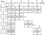
次に図3を参照すると、本発明の別の実施形態では、第1センサノード46、第2センサノード48、および第3センサノード50が、ゲートウェイ装置20とワイヤレス通信し、ゲートウェイ装置20に患者データパケット36をシーケンス順に送信する。すなわち、第1センサノード46、第2センサノード48、および第3センサノード50は、各ノードが関連付けられる通信フレーム32内のスロット30に従ってデータパケット36を送信する。図3に示されるように、第1センサノード46は、その関連付けられるスロットで、第1周波数、次いで第2周波数でデータパケット36を送信する。別個の第1周波数と第2周波数での第1センサノード46によるデータパケット36の反復送信の後、第2センサノード48は、その割り当てられたスロット30で、第2周波数、次いで第1周波数でデータパケット36を送信する。第2センサノード48による第2周波数でのデータパケット36のこの初期送信が、第1センサノード46によるその第2周波数での送信の後に続くので、ゲートウェイ装置20は、スロット30間で第1センサノード46から第2センサノード48に遷移するとき、引き続き第2周波数に同調される。同様に、第2センサノード48による送信に続いて、第3センサノード50は、当初は第1周波数、次いで第2周波数で患者データ当初を送信する。したがってこの場合も、ゲートウェイ装置20は、第2センサノード48から第3センサノード50に遷移するときに、引き続き第1周波数に同調することができる。したがって、センサノード46、48、50によるデータパケット36の各送信と同期したままとなるためにゲートウェイ装置20で必要とされる周波数同調および周波数切替えは、図3に示される実施形態では削減される。 Referring now to FIG. 3, in another embodiment of the present invention, a
次に図4を参照すると、別の実施形態では、各通信フレーム32が複数の定義済みサブフレーム54、56に分割される。図4に示されるように、通信フレーム32はさらに、第1サブフレーム54および第2サブフレーム56からなり、各サブフレームは同一の数のスロット58を含む。各センサノードは、各サブフレーム内の同一のスロット58に対応する(すなわち、第1センサノード46は、第1サブフレームおよび第2サブフレームのそれぞれの第1スロットで送信する)。センサネットワーク18(図1に図示)内の複数のワイヤレスセンサ16からのデータパケット36を介する患者データの送信が、2つのサブフレームに分割される。すなわち、図4に示されるように、第1センサノード46、第2センサノード48、および第3センサノード50のそれぞれは、第1サブフレーム54中に第1周波数でデータパケット36を送信するようにプログラムされる。各センサによるデータパケット36の送信は、第1サブフレーム54内の各センサの関連付けられる時間スロット58に従って順序付けられる。第1サブフレーム54の完了時に、第2サブフレーム56に入り、その間に、第1センサノード46、第2センサノード48、および第3センサノード50のそれぞれが、第2の別個の周波数でそれぞれのデータパケット36を再送信するようにプログラムされる。第1サブフレーム54中の送信と同様に、第2サブフレーム56内の各センサによるデータパケット36の送信もやはり、第2サブフレーム56内の各センサの関連付けられる時間スロット58に従って順序付けられる。 Referring now to FIG. 4, in another embodiment, each
上述の第1サブフレーム54および第2サブフレーム56への通信フレームの分割は、指定の周波数での患者データ伝送期間を延長することを可能にする。すなわち、センサノード46、48、50によって第1サブフレーム54で送信されるすべてのデータパケット36が、第1周波数で送信される。その後で、センサノードによって第2サブフレーム56で再送信されるすべてのデータパケット36が、第2周波数で送信される。そのような送信プロトコルは、ゲートウェイ装置20が、異なる周波数に再同調する必要なしに、サブフレームの全体で単一周波数に同調したままにすることを可能にする。センサノード伝送と同期したままにするためにゲートウェイ装置20によって必要とされる再同調の数の削減により、エネルギー消費が削減され、再同調に関連する時間遅延が解消される。 The division of the communication frame into the
ビーコンメッセージ34および患者データパケット36についての複数の伝送パターンのそれぞれを上記で別々に説明したが、互いに一緒に伝送パターンを使用できることが想定される。すなわち、ゲートウェイ装置20と複数のワイヤレスセンサ16の間のデータ転送のために使用される伝送パターンを、連続する通信フレーム32間で変更することができる。そのような伝送パターンの変更により、混信無線伝送のデューティサイクルに従って伝送パターンを変更して、混信無線伝送との混信を回避することができるので、ワイヤレス通信をさらに改善し、堅牢にすることができる。 Although each of the plurality of transmission patterns for
別の実施形態では、周波数可変能力/ホッピングがゲートウェイ装置20によって通信フレーム32間で使用され、他のゲートウェイまたは他の無線システムで使用されていない利用可能な無線通信路(例えば2.4GHz ISM帯域の中)が選択される。すなわち、ゲートウェイ装置20は(図1に示されるスーパーバイザゲートウェイ29により)、後続の通信フレーム32によってそのビーコンメッセージ34中に使用される伝送周波数に、ゲートウェイ装置20およびワイヤレスセンサ16によって送信される周波数のうちの少なくとも1つを以前に未使用であった周波数に変更するように指令する。通信フレーム32間で使用される追加の周波数ホッピングはさらに、伝送の変動性をさらに高めることによってNAP10(図1に図示)でのビーコンメッセージ34およびデータパケット36の伝送が成功することを保証する。ゲートウェイ装置20はまた、将来の通信のために1組の周波数パターンをブロードキャストすることができる。 In another embodiment, frequency variable capability / hopping is used between the communication frames 32 by the
したがって、本発明の一実施形態によれば、ワイヤレス患者監視システムは、患者から患者データを取得するように構成された複数のセンサノードと、複数の定義済み通信フレームのために複数のセンサノードと双方向ワイヤレス通信するゲートウェイ装置とを含む。ゲートウェイ装置は、複数の周波数のそれぞれで複数のセンサノードにビーコンメッセージを送信するように構成される。複数のセンサノードはさらに、ゲートウェイ装置からビーコンメッセージを受信し、複数の周波数のそれぞれで、取得した患者データをゲートウェイ装置に送信する。 Thus, according to one embodiment of the present invention, a wireless patient monitoring system includes a plurality of sensor nodes configured to obtain patient data from a patient, and a plurality of sensor nodes for a plurality of predefined communication frames. And a gateway device for two-way wireless communication. The gateway device is configured to transmit a beacon message to a plurality of sensor nodes at each of a plurality of frequencies. The plurality of sensor nodes further receive a beacon message from the gateway device and transmit the acquired patient data to the gateway device at each of the plurality of frequencies.
本発明の別の態様によれば、患者監視のための方法は、患者から健康データを取得するために患者上に複数のワイヤレスセンサを配置するステップと、複数のワイヤレスセンサのそれぞれを動作フレーム内のタイムスロットに割り当てることによって複数のワイヤレスセンサをゲートウェイコントローラと関連付けるステップとを含む。この方法はまた、動作フレーム中にワイヤレスセンサを活動化するためにゲートウェイコントローラから複数のワイヤレスセンサにビーコン信号を送信するステップと、ビーコン信号に応答して、動作フレーム中に複数のデータパケットを介して複数のワイヤレスセンサからゲートウェイコントローラに健康データを送信するステップとを含む。ビーコン信号およびデータパケットのうちの少なくとも1つは、動作フレーム中に第1周波数チャネルおよび第2周波数チャネルを介して送信される。 In accordance with another aspect of the present invention, a method for patient monitoring includes placing a plurality of wireless sensors on a patient to obtain health data from the patient, and placing each of the plurality of wireless sensors within an operating frame. Associating a plurality of wireless sensors with a gateway controller by assigning to a plurality of time slots. The method also includes transmitting a beacon signal from the gateway controller to the plurality of wireless sensors to activate the wireless sensor during the operation frame, and via the plurality of data packets during the operation frame in response to the beacon signal. Transmitting health data from the plurality of wireless sensors to the gateway controller. At least one of the beacon signal and the data packet is transmitted over the first frequency channel and the second frequency channel during the operation frame.
本発明のさらに別の態様によれば、ワイヤレスセンサ通信システムは、監視されるシステムからシステムデータを取得するように構成されたセンサネットワークと、センサネットワークに近接して配置され、センサネットワークとワイヤレス通信するコントローラとを含む。センサネットワークとコントローラのそれぞれは、第1周波数チャネル(F1)および第2周波数チャネル(F2)を介してワイヤレス信号を順次送信および受信し、複数の通信フレームのそれぞれの間に少なくとも1度、第1周波数チャネルと第2周波数チャネルとの間で切り替わるように構成され、ワイヤレス信号は活動化信号およびシステムデータを含む。 In accordance with yet another aspect of the present invention, a wireless sensor communication system is configured to obtain system data from a monitored system, and is disposed proximate to the sensor network to wirelessly communicate with the sensor network. Controller. Each of the sensor network and the controller sequentially transmits and receives wireless signals via the first frequency channel (F1) and the second frequency channel (F2), and at least once between each of the plurality of communication frames. The wireless signal includes an activation signal and system data configured to switch between the frequency channel and the second frequency channel.
本発明を好ましい実施形態によって説明したが、はっきりと述べたもの以外の均等物、代替実施形態、および修正形態が可能であり、それらは添付の特許請求の範囲内にあることを理解されたい。また、図面の符号に対応する特許請求の範囲中の符号は、単に本願発明の理解をより容易にするために用いられているものであり、本願発明の範囲を狭める意図で用いられたものではない。そして、本願の特許請求の範囲に記載した事項は、明細書に組み込まれ、明細書の記載事項の一部となる。 While the invention has been described in terms of preferred embodiments, it is to be understood that equivalents, alternative embodiments, and modifications other than those explicitly described are possible and are within the scope of the appended claims. Further, the reference numerals in the claims corresponding to the reference numerals in the drawings are merely used for easier understanding of the present invention, and are not intended to narrow the scope of the present invention. Absent. The matters described in the claims of the present application are incorporated into the specification and become a part of the description items of the specification.
10 Network Around a Patient(NAP)
12 医療施設
14 患者
16 身体装着センサ
20 ゲートウェイコントローラ装置
22 集積回路トランシーバ
24 マイクロコントローラ
26 感知装置
28 インフラストラクチャ
29 スーパーバイザゲートウェイ装置
30 時間スロット
32 通信フレーム
34 ブロードキャストビーコンメッセージ
36 データパケット
38 関連間隔
40 初期ビーコンメッセージ
42 追従ビーコンメッセージ
44 時間枠
46 第1センサノード
48 第2センサノード
50 第3センサノード
52 時間枠
54 第1サブフレーム
56 第2サブフレーム
58 スロット10 Network Around a Patient (NAP)
DESCRIPTION OF
Claims (10)
Translated fromJapanese複数の定義済み通信フレーム(32)のための前記複数のセンサノード(16)と双方向ワイヤレス通信するゲートウェイ装置(20)であって、複数の周波数のそれぞれで前記複数のセンサノードにビーコンメッセージ(34)を送信するように構成されるゲートウェイ装置(20)と
を備えるワイヤレス患者監視システム(10)であって、
前記複数のセンサノード(16)がさらに、
前記ゲートウェイ装置(20)から前記ビーコンメッセージ(34)を受信し、
前記複数の周波数のそれぞれで、取得した患者データを前記ゲートウェイ装置(20)に送信する
ように構成されるワイヤレス患者監視システム(10)。A plurality of sensor nodes (16) configured to obtain patient data from the patient (14);
A gateway device (20) for two-way wireless communication with the plurality of sensor nodes (16) for a plurality of predefined communication frames (32), wherein a beacon message ( 34) a wireless patient monitoring system (10) comprising a gateway device (20) configured to transmit
The plurality of sensor nodes (16) further includes:
Receiving the beacon message (34) from the gateway device (20);
A wireless patient monitoring system (10) configured to transmit acquired patient data to the gateway device (20) at each of the plurality of frequencies.
前記ゲートウェイ装置(20)がさらに、前記患者データを受信するために前記第1周波数に同調し、前記患者データが所定の時間限度(44)内に受信されない場合に前記第2周波数に同調するように構成される請求項2記載のワイヤレス患者監視システム(10)。The plurality of sensor nodes (16) are further tuned to the first frequency to receive the beacon signal (34), and the beacon signal (34) transmitted on the first frequency is a predetermined time limit ( 44) configured to tune to the second frequency if not received within
The gateway device (20) is further tuned to the first frequency for receiving the patient data and tuned to the second frequency if the patient data is not received within a predetermined time limit (44). The wireless patient monitoring system (10) of claim 2, wherein the wireless patient monitoring system (10) is configured.
Applications Claiming Priority (2)
| Application Number | Priority Date | Filing Date | Title |
|---|---|---|---|
| US11/862,681US8199000B2 (en) | 2007-09-27 | 2007-09-27 | System and method for interference mitigation in a wireless sensor network |
| US11/862,681 | 2007-09-27 |
Publications (2)
| Publication Number | Publication Date |
|---|---|
| JP2009089379Atrue JP2009089379A (en) | 2009-04-23 |
| JP5297130B2 JP5297130B2 (en) | 2013-09-25 |
Family
ID=40384571
Family Applications (1)
| Application Number | Title | Priority Date | Filing Date |
|---|---|---|---|
| JP2008243475AActiveJP5297130B2 (en) | 2007-09-27 | 2008-09-24 | System and method for interference mitigation in a wireless sensor network |
Country Status (3)
| Country | Link |
|---|---|
| US (1) | US8199000B2 (en) |
| JP (1) | JP5297130B2 (en) |
| DE (1) | DE102008037388B4 (en) |
Cited By (6)
| Publication number | Priority date | Publication date | Assignee | Title |
|---|---|---|---|---|
| WO2011089928A1 (en)* | 2010-01-19 | 2011-07-28 | 三菱電機株式会社 | Data collection system, data collection device, wireless communication device, and communication method for collecting data |
| WO2012111559A1 (en)* | 2011-02-18 | 2012-08-23 | 株式会社日立製作所 | Sensor device and control method thereof |
| JP2017084376A (en)* | 2012-03-21 | 2017-05-18 | パワーキャスト コーポレイションPowercast Corporation | Wireless sensor system, method and device with switch and outlet control |
| US10149370B2 (en) | 2015-05-04 | 2018-12-04 | Powercast Corporation | Automated system for lighting control |
| US10455663B2 (en) | 2013-10-23 | 2019-10-22 | Powercast Corporation | Automated system for lighting control |
| US10979961B2 (en) | 2016-10-07 | 2021-04-13 | Powercast Corporation | Automated system for lighting control |
Families Citing this family (31)
| Publication number | Priority date | Publication date | Assignee | Title |
|---|---|---|---|---|
| US20090109948A1 (en)* | 2007-10-29 | 2009-04-30 | Infineon Technologies Ag | Radio communication device for generating and transmitting data, radio communication device for receiving and decoding data, method for transmitting data and method for receiving data |
| EP2255582B1 (en)* | 2008-03-11 | 2011-11-30 | Philips Intellectual Property & Standards GmbH | Time synchronization of a plurality of different wireless networks with data sensors |
| US8787266B2 (en)* | 2008-06-13 | 2014-07-22 | Infineon Technologies Ag | Medium access control in industrial and automotive wireless with combined wired and wireless sensor networks |
| US8289184B2 (en)* | 2008-08-27 | 2012-10-16 | Murphy Industries, Llc | Wireless sensor network |
| US8373576B2 (en)* | 2008-08-27 | 2013-02-12 | Murphy Wireless, Llc | Wireless sensor network with variable priority |
| ES2388488T3 (en)* | 2008-12-23 | 2012-10-15 | Koninklijke Philips Electronics N.V. | Combination of body coupled communication and radio frequency communication |
| JP5332840B2 (en)* | 2009-04-08 | 2013-11-06 | ソニー株式会社 | Wireless communication apparatus, wireless communication system, wireless communication method, and program |
| KR101295871B1 (en)* | 2009-11-27 | 2013-08-12 | 한국전자통신연구원 | Data transmission method in sensor network |
| US9000914B2 (en)* | 2010-03-15 | 2015-04-07 | Welch Allyn, Inc. | Personal area network pairing |
| US8907782B2 (en) | 2010-06-30 | 2014-12-09 | Welch Allyn, Inc. | Medical devices with proximity detection |
| US8957777B2 (en) | 2010-06-30 | 2015-02-17 | Welch Allyn, Inc. | Body area network pairing improvements for clinical workflows |
| HU230974B1 (en)* | 2011-09-06 | 2019-07-29 | General Electric Company | Monitoring system and method |
| EP2801079A1 (en)* | 2012-01-06 | 2014-11-12 | Koninklijke Philips N.V. | Emergency response and tracking using lighting networks |
| KR101904745B1 (en)* | 2012-01-26 | 2018-11-21 | 삼성전자주식회사 | A main hub, a sub hub and a sensor node communicate in a wireless body area network including at least one sub hub and a methode thereof |
| US9433014B2 (en)* | 2012-02-14 | 2016-08-30 | Lg Electronics Inc. | Device to device communication method and device for performing same |
| US20130336130A1 (en)* | 2012-06-13 | 2013-12-19 | Honeywell International Inc. | System and Method for Detecting Jamming in Wireless Networks |
| US9183732B2 (en)* | 2012-08-07 | 2015-11-10 | Tektone Sound & Signal Mfg., Inc. | Dual band nurse call system |
| KR102083563B1 (en)* | 2013-07-22 | 2020-03-03 | 삼성전자주식회사 | Method of controlloing interference in wireless power transfer system and apparatus thereof |
| US9516141B2 (en) | 2013-08-29 | 2016-12-06 | Verizon Patent And Licensing Inc. | Method and system for processing machine-to-machine sensor data |
| WO2015087870A1 (en)* | 2013-12-10 | 2015-06-18 | 株式会社 東芝 | Communication processor, integrated circuit, wireless communication terminal, memory card, wireless communication device, and wireless communication method |
| US9706923B2 (en) | 2014-02-25 | 2017-07-18 | General Electric Company | System and method for adaptive interference mitigation in wireless sensor network |
| US10617357B2 (en) | 2014-08-24 | 2020-04-14 | Halo Wearables, Llc | Swappable wearable device |
| US9781613B2 (en) | 2015-10-22 | 2017-10-03 | General Electric Company | System and method for proactive communication network management based upon area occupancy |
| WO2017223339A1 (en)* | 2016-06-23 | 2017-12-28 | Mayo Foundation For Medical Education And Research | Proximity based fall and distress detection systems and methods |
| US10721683B2 (en)* | 2017-08-18 | 2020-07-21 | Blackberry Limited | Method and system for battery life improvement for low power devices in wireless sensor networks |
| US10674443B2 (en) | 2017-08-18 | 2020-06-02 | Blackberry Limited | Method and system for battery life improvement for low power devices in wireless sensor networks |
| US11403888B2 (en)* | 2018-09-24 | 2022-08-02 | Gojo Industries, Inc. | Method and system for using data packet beaconing to determine compliance with protocols |
| EP3738503B1 (en)* | 2019-05-15 | 2024-05-01 | Siemens Healthineers AG | Adjustment of a transmission frequency of a physiological monitoring unit |
| US11382028B2 (en)* | 2020-10-23 | 2022-07-05 | Bluwireless Technology Limited | Wireless communication for vehicle based node |
| CN114143739B (en)* | 2021-11-12 | 2025-01-10 | 北京天玛智控科技股份有限公司 | Wireless communication method and system applicable to sensors downhole |
| FR3157040A1 (en)* | 2023-12-13 | 2025-06-20 | Commissariat à l'Energie Atomique et aux Energies Alternatives | Bluetooth Low Energy telecommunication method implemented between a first telecommunication device and a second telecommunication device |
Citations (2)
| Publication number | Priority date | Publication date | Assignee | Title |
|---|---|---|---|---|
| JP2000037356A (en)* | 1998-07-23 | 2000-02-08 | Denso Corp | Biological signal telemetry instrument |
| JP2006121393A (en)* | 2004-10-21 | 2006-05-11 | Matsushita Electric Ind Co Ltd | Wireless communication system and wireless communication device |
Family Cites Families (32)
| Publication number | Priority date | Publication date | Assignee | Title |
|---|---|---|---|---|
| US5153584A (en) | 1989-03-17 | 1992-10-06 | Cardiac Evaluation Center, Inc. | Miniature multilead biotelemetry and patient location system |
| US5335664A (en) | 1991-09-17 | 1994-08-09 | Casio Computer Co., Ltd. | Monitor system and biological signal transmitter therefor |
| US5550536A (en)* | 1994-08-17 | 1996-08-27 | Texas Instruments Deutschland Gmbh | Circuit frequency following technique transponder resonant |
| US5748103A (en) | 1995-11-13 | 1998-05-05 | Vitalcom, Inc. | Two-way TDMA telemetry system with power conservation features |
| US6870484B1 (en) | 1999-03-24 | 2005-03-22 | Ge Marquette Medical Systems, Inc. | Patient monitoring systems having two-way communication |
| US6984207B1 (en) | 1999-09-14 | 2006-01-10 | Hoana Medical, Inc. | Passive physiological monitoring (P2M) system |
| US6616606B1 (en) | 2000-05-19 | 2003-09-09 | Welch Allyn Protocol, Inc. | Patient monitoring system |
| US7689437B1 (en) | 2000-06-16 | 2010-03-30 | Bodymedia, Inc. | System for monitoring health, wellness and fitness |
| US6749566B2 (en) | 2001-02-14 | 2004-06-15 | Draeger Medical Systems, Inc. | Patient monitoring area network |
| EP1374194A2 (en)* | 2001-03-30 | 2004-01-02 | Hill-Rom Services, Inc. | Hospital bed and network system |
| WO2002089667A1 (en) | 2001-05-03 | 2002-11-14 | Telzuit Technologies, Inc. | Wireless medical monitoring apparatus and system |
| US20030162556A1 (en) | 2002-02-28 | 2003-08-28 | Libes Michael A. | Method and system for communication between two wireless-enabled devices |
| US7286040B2 (en)* | 2002-03-14 | 2007-10-23 | Eices Research, Inc. | Cooperative vehicular identification system |
| US7020508B2 (en) | 2002-08-22 | 2006-03-28 | Bodymedia, Inc. | Apparatus for detecting human physiological and contextual information |
| US20040203381A1 (en) | 2002-12-31 | 2004-10-14 | Cahn Janet E. | Method and apparatus for data transfer |
| AU2004224345B2 (en) | 2003-03-21 | 2010-02-18 | Welch Allyn, Inc. | Personal status physiologic monitor system and architecture and related monitoring methods |
| US7129836B2 (en) | 2003-09-23 | 2006-10-31 | Ge Medical Systems Information Technologies, Inc. | Wireless subject monitoring system |
| WO2005062232A2 (en) | 2003-12-19 | 2005-07-07 | Philips Intellectual Property & Standards Gmbh | Patient network with wireless medical apparatuses and allocation thereof to a patient and his network |
| US20060009697A1 (en) | 2004-04-07 | 2006-01-12 | Triage Wireless, Inc. | Wireless, internet-based system for measuring vital signs from a plurality of patients in a hospital or medical clinic |
| EP1773185A4 (en) | 2004-06-18 | 2009-08-19 | Vivometrics Inc | Systems and methods for real-time physiological monitoring |
| EP1781162A1 (en) | 2004-07-09 | 2007-05-09 | Tadiran Spectralink Ltd. | Wearable device, system and method for measuring vital parameters |
| US20080027679A1 (en) | 2004-07-21 | 2008-01-31 | Dror Shklarski | Wearable Device, System and Method for Measuring Physiological and/or Environmental Parameters |
| DE602005022348D1 (en) | 2004-10-29 | 2010-08-26 | Draeger Medical Systems Inc | AUTOMATIC SWITCHING BETWEEN WIRELESS PAN / LAN |
| DE602005011847D1 (en) | 2004-11-08 | 2009-01-29 | Philips Intellectual Property | SAFE IDENTIFICATION AND ASSIGNMENT OF WIRELESS SENSORS |
| US10709330B2 (en) | 2004-11-15 | 2020-07-14 | Koninklijke Philips N.V. | Ambulatory medical telemetry device having an audio indicator |
| US20060224048A1 (en) | 2005-03-22 | 2006-10-05 | Aware Technologies, Inc. | Wearable personal area data network |
| US7889069B2 (en) | 2005-04-01 | 2011-02-15 | Codman & Shurtleff, Inc. | Wireless patient monitoring system |
| CN100471445C (en) | 2005-08-01 | 2009-03-25 | 周常安 | Patch type physiological monitoring device |
| US7609155B2 (en)* | 2005-08-25 | 2009-10-27 | Hinkamp Thomas J | System providing medical personnel with immediate critical data for emergency treatments |
| US7595723B2 (en) | 2005-11-14 | 2009-09-29 | Edwards Lifesciences Corporation | Wireless communication protocol for a medical sensor system |
| US8016776B2 (en) | 2005-12-02 | 2011-09-13 | Medtronic, Inc. | Wearable ambulatory data recorder |
| US20090023391A1 (en) | 2006-02-24 | 2009-01-22 | Koninklijke Philips Electronics N. V. | Wireless body sensor network |
- 2007
- 2007-09-27USUS11/862,681patent/US8199000B2/enactiveActive
- 2008
- 2008-09-24DEDE102008037388.5Apatent/DE102008037388B4/enactiveActive
- 2008-09-24JPJP2008243475Apatent/JP5297130B2/enactiveActive
Patent Citations (2)
| Publication number | Priority date | Publication date | Assignee | Title |
|---|---|---|---|---|
| JP2000037356A (en)* | 1998-07-23 | 2000-02-08 | Denso Corp | Biological signal telemetry instrument |
| JP2006121393A (en)* | 2004-10-21 | 2006-05-11 | Matsushita Electric Ind Co Ltd | Wireless communication system and wireless communication device |
Cited By (17)
| Publication number | Priority date | Publication date | Assignee | Title |
|---|---|---|---|---|
| WO2011089928A1 (en)* | 2010-01-19 | 2011-07-28 | 三菱電機株式会社 | Data collection system, data collection device, wireless communication device, and communication method for collecting data |
| JP5312612B2 (en)* | 2010-01-19 | 2013-10-09 | 三菱電機株式会社 | Data collection system, data collection device, wireless communication device, and communication method for data collection |
| US9398614B2 (en) | 2010-01-19 | 2016-07-19 | Mitsubishi Electric Corporation | Data collection system, data collection device, wireless communication device, and communication method for collecting data |
| WO2012111559A1 (en)* | 2011-02-18 | 2012-08-23 | 株式会社日立製作所 | Sensor device and control method thereof |
| JP2012173434A (en)* | 2011-02-18 | 2012-09-10 | Hitachi Ltd | Sensor device and control method of the same |
| JP2017084376A (en)* | 2012-03-21 | 2017-05-18 | パワーキャスト コーポレイションPowercast Corporation | Wireless sensor system, method and device with switch and outlet control |
| US12369095B2 (en) | 2012-03-21 | 2025-07-22 | Powercast Corporation | Wireless sensor system, method and apparatus with switch and outlet control |
| US11917519B2 (en) | 2012-03-21 | 2024-02-27 | Powercast Corporation | Wireless sensor system, method and apparatus with switch and outlet control |
| US11457395B2 (en) | 2012-03-21 | 2022-09-27 | Powercast Corporation | Wireless sensor system, method and apparatus with switch and outlet control |
| US10638399B2 (en) | 2012-03-21 | 2020-04-28 | Powercast Corporation | Wireless sensor system, method and apparatus with switch and outlet control |
| US11102869B2 (en) | 2013-10-23 | 2021-08-24 | Powercast Corporation | Automated system for lighting control |
| US10455663B2 (en) | 2013-10-23 | 2019-10-22 | Powercast Corporation | Automated system for lighting control |
| US11039524B2 (en) | 2015-05-04 | 2021-06-15 | Powercast Corporation | Automated system for lighting control |
| US10524337B2 (en) | 2015-05-04 | 2019-12-31 | Powercast Corporation | Automated system for lighting control |
| US10149370B2 (en) | 2015-05-04 | 2018-12-04 | Powercast Corporation | Automated system for lighting control |
| US10979961B2 (en) | 2016-10-07 | 2021-04-13 | Powercast Corporation | Automated system for lighting control |
| US11696211B2 (en) | 2016-10-07 | 2023-07-04 | Powercast Corporation | Automated system for lighting control |
Also Published As
| Publication number | Publication date |
|---|---|
| US8199000B2 (en) | 2012-06-12 |
| JP5297130B2 (en) | 2013-09-25 |
| DE102008037388A1 (en) | 2009-04-02 |
| US20090088605A1 (en) | 2009-04-02 |
| DE102008037388B4 (en) | 2023-06-22 |
Similar Documents
| Publication | Publication Date | Title |
|---|---|---|
| JP5297130B2 (en) | System and method for interference mitigation in a wireless sensor network | |
| KR101307607B1 (en) | Improvements to short-range wireless networks | |
| KR101244555B1 (en) | Improvements to body area networks | |
| CN102342136B (en) | The improvement of human body local area network | |
| JP5757679B2 (en) | Wireless network protocol for hearing systems | |
| US10891248B2 (en) | Configuring wireless communications according to multiple communication protocols | |
| EP3255931B1 (en) | Configuring wireless communications and an advertising event according to multiple communication protocols | |
| JP5559791B2 (en) | Medium access control (MAC) protocol for body area networks | |
| US20150238082A1 (en) | System and method for adaptive interference mitigation in wireless sensor network | |
| US10129907B2 (en) | Implant access in the medical implant communications service band | |
| SG124397A1 (en) | New wlan tdm protocol | |
| CA2871466A1 (en) | Scalable protocol for large wsns having low duty cycle end nodes | |
| WO2013077149A1 (en) | Communication system, and communication device | |
| Goyal et al. | TDMA based delay sensitive and energy efficient protocol for WBAN | |
| JP2025520151A (en) | Efficient unicast superframe communication | |
| EP2226958A1 (en) | Wireless sensor networks with data reception acknowledgement | |
| WO2013077150A1 (en) | Communication system, and communication device | |
| Giachoudis et al. | Investigation of suitable mac protocols for optical wireless body-area networks | |
| Gama et al. | A time-slot scheduling algorithm for e-health wireless sensor networks | |
| JP5840469B2 (en) | Communication system and communication apparatus | |
| Barge | A Study of Packet Loss Caused by Interference between the Bluetooth Component of a Telecardiology System and Residential Microwave Ovens | |
| Bhandari | Priority-Based Adaptive MAC for Wireless Body Area Networks in Unlicensed Bands |
Legal Events
| Date | Code | Title | Description |
|---|---|---|---|
| RD04 | Notification of resignation of power of attorney | Free format text:JAPANESE INTERMEDIATE CODE: A7424 Effective date:20110214 | |
| A621 | Written request for application examination | Free format text:JAPANESE INTERMEDIATE CODE: A621 Effective date:20110908 | |
| A521 | Request for written amendment filed | Free format text:JAPANESE INTERMEDIATE CODE: A523 Effective date:20120906 | |
| A977 | Report on retrieval | Free format text:JAPANESE INTERMEDIATE CODE: A971007 Effective date:20130212 | |
| A131 | Notification of reasons for refusal | Free format text:JAPANESE INTERMEDIATE CODE: A131 Effective date:20130219 | |
| A521 | Request for written amendment filed | Free format text:JAPANESE INTERMEDIATE CODE: A523 Effective date:20130403 | |
| TRDD | Decision of grant or rejection written | ||
| A01 | Written decision to grant a patent or to grant a registration (utility model) | Free format text:JAPANESE INTERMEDIATE CODE: A01 Effective date:20130521 | |
| A61 | First payment of annual fees (during grant procedure) | Free format text:JAPANESE INTERMEDIATE CODE: A61 Effective date:20130614 | |
| R150 | Certificate of patent or registration of utility model | Ref document number:5297130 Country of ref document:JP Free format text:JAPANESE INTERMEDIATE CODE: R150 Free format text:JAPANESE INTERMEDIATE CODE: R150 | |
| R250 | Receipt of annual fees | Free format text:JAPANESE INTERMEDIATE CODE: R250 | |
| R250 | Receipt of annual fees | Free format text:JAPANESE INTERMEDIATE CODE: R250 | |
| R250 | Receipt of annual fees | Free format text:JAPANESE INTERMEDIATE CODE: R250 | |
| R250 | Receipt of annual fees | Free format text:JAPANESE INTERMEDIATE CODE: R250 | |
| R250 | Receipt of annual fees | Free format text:JAPANESE INTERMEDIATE CODE: R250 | |
| R250 | Receipt of annual fees | Free format text:JAPANESE INTERMEDIATE CODE: R250 | |
| R250 | Receipt of annual fees | Free format text:JAPANESE INTERMEDIATE CODE: R250 | |
| R250 | Receipt of annual fees | Free format text:JAPANESE INTERMEDIATE CODE: R250 | |
| R250 | Receipt of annual fees | Free format text:JAPANESE INTERMEDIATE CODE: R250 | |
| S111 | Request for change of ownership or part of ownership | Free format text:JAPANESE INTERMEDIATE CODE: R313113 | |
| R250 | Receipt of annual fees | Free format text:JAPANESE INTERMEDIATE CODE: R250 | |
| R350 | Written notification of registration of transfer | Free format text:JAPANESE INTERMEDIATE CODE: R350 |