JP2009089041A - Wireless communication apparatus and reception quality estimation method - Google Patents
Wireless communication apparatus and reception quality estimation methodDownload PDFInfo
- Publication number
- JP2009089041A JP2009089041AJP2007256312AJP2007256312AJP2009089041AJP 2009089041 AJP2009089041 AJP 2009089041AJP 2007256312 AJP2007256312 AJP 2007256312AJP 2007256312 AJP2007256312 AJP 2007256312AJP 2009089041 AJP2009089041 AJP 2009089041A
- Authority
- JP
- Japan
- Prior art keywords
- signal
- time
- radio
- signal sequence
- time zone
- Prior art date
- Legal status (The legal status is an assumption and is not a legal conclusion. Google has not performed a legal analysis and makes no representation as to the accuracy of the status listed.)
- Withdrawn
Links
Images


Landscapes
- Monitoring And Testing Of Transmission In General (AREA)
Abstract
Translated fromJapaneseDescription
Translated fromJapanese本発明は、受信した無線信号を周波数領域における信号系列に変換し、前記無線信号に含まれる既知信号に基づいて無線信号の伝搬路の状態を推定した伝搬路推定情報を算出する無線通信装置、及び当該無線通信装置における受信品質推定方法に関する。 The present invention relates to a radio communication apparatus that converts a received radio signal into a signal sequence in a frequency domain and calculates propagation path estimation information obtained by estimating a propagation path state of the radio signal based on a known signal included in the radio signal, And a reception quality estimation method in the wireless communication apparatus.
近年、直交周波数分割多重(OFDM)など、マルチキャリア方式を用いることによって通信容量を増大させた無線通信システムが実現されている。このような無線通信システムでは、通信を実行する無線通信装置に対して、無線信号の受信品質に応じて適応的にサブキャリア数などの無線リソースを分配することによって、無線通信システム全体として取り扱うことができる通信容量をさらに増大する方法が導入されている。 In recent years, wireless communication systems having increased communication capacity by using a multicarrier scheme such as orthogonal frequency division multiplexing (OFDM) have been realized. In such a wireless communication system, the wireless communication apparatus that performs communication is handled as the whole wireless communication system by adaptively distributing wireless resources such as the number of subcarriers according to the reception quality of the wireless signal. A method for further increasing the communication capacity that can be used has been introduced.
このような無線リソースの配分の決定に用いられる受信品質として、信号対雑音比(SNR)が広く用いられている。 A signal-to-noise ratio (SNR) is widely used as the reception quality used for determining such radio resource allocation.
具体的には、時間的に離散した無線信号を受信した無線通信装置は、当該無線信号に対して高速フーリエ変換(FFT)を実行し、周波数領域における信号系列に変換する。さらに、無線通信装置は、振幅や位相などの設定値が送信側と受信側とにおいて既知である既知信号(既知シンボル)の状態に基づいて、各既知信号のI成分及びQ成分の平均である平均信号ベクトル(伝搬路推定情報)を算出するとともに、各既知信号における信号ベクトルの分散に基づいて雑音電力を算出する。無線通信装置は、算出した平均信号ベクトルと雑音電力とを用いて無線信号のSNRを推定する(例えば、特許文献1)。
ところで、OFDMなど、マルチキャリア方式を用いる無線通信システムでは、シングルキャリア方式を用いる無線通信システムと比較して、一般的にシンボル当たりの時間が長い。また、マルチキャリア方式を用いる無線通信システムでは、シングルキャリア方式を用いる無線通信システムよりも広帯域を占有するため、使用周波数帯域によって受信品質が変動し得る。 By the way, a radio communication system using a multicarrier scheme such as OFDM generally has a longer time per symbol than a radio communication system using a single carrier scheme. In addition, since a wireless communication system using a multicarrier system occupies a wider band than a wireless communication system using a single carrier system, reception quality may vary depending on the frequency band used.
このため、上述した既知信号の平均信号ベクトル(伝搬路推定情報)と雑音電力とに基づいて無線信号の受信品質(SNR)を推定する方法では、無線信号の受信品質の推定精度が低下するといった問題があった。 For this reason, in the method of estimating the reception quality (SNR) of the radio signal based on the average signal vector (propagation channel estimation information) of the known signal and the noise power, the estimation accuracy of the reception quality of the radio signal is reduced. There was a problem.
そこで、本発明は、このような状況に鑑みてなされたものであり、既知信号に基づいて無線信号の受信品質を推定する場合において、特に、マルチキャリア方式が用いられる場合において、より正確に無線信号の受信品質を推定することができる無線通信装置及び受信品質推定方法を提供することを目的とする。 Therefore, the present invention has been made in view of such a situation, and in the case where the reception quality of a radio signal is estimated based on a known signal, particularly when the multi-carrier scheme is used, the radio is more accurately performed. An object of the present invention is to provide a radio communication apparatus and a reception quality estimation method capable of estimating the reception quality of a signal.
上述した問題を解決するため、本発明は、次のような特徴を有している。まず、本発明の第1の特徴は、受信した無線信号(無線信号RS)を周波数領域における信号系列(信号系列S2)に変換し、前記無線信号に含まれる既知信号(既知シンボルSP)に基づいて前記無線信号の伝搬路の状態を推定した伝搬路推定情報(伝搬路推定情報H^[k])を算出する無線通信装置(無線基地局100)であって、前記伝搬路推定情報を時間領域における信号系列である時間領域信号系列(信号系列S3)に再変換する再変換部(周波数領域/時間領域変換部160)と、前記再変換部によって再変換された前記時間領域信号系列が含まれる全時間帯のうち、前記時間領域信号系列の振幅が所定の閾値を超える信号成分を含む第1時間帯(時間帯ts)と、前記第1時間帯以外の時間帯である第2時間帯(時間帯tn)とに分割する分割部(時間領域SNR推定部170)と、前記第1時間帯に含まれる前記時間領域信号系列に基づいて、前記無線信号の信号電力(W-Na)を算出するとともに、前記第2時間帯に含まれる前記時間領域信号系列に基づいて、雑音電力(Na)を算出することによって、前記無線信号の信号対雑音比を推定するSNR推定部(時間領域SNR推定部170)とを備えることを要旨とする。In order to solve the problems described above, the present invention has the following features. First, the first feature of the present invention is that a received radio signal (radio signal RS) is converted into a signal sequence (signal sequence S2) in the frequency domain, and converted into a known signal (known symbolSP ) included in the radio signal. A wireless communication apparatus (radio base station 100) that calculates propagation path estimation information (propagation path estimation information H ^ [k]) obtained by estimating a propagation path state of the radio signal based on the propagation path estimation information. A re-transformer (frequency domain / time-domain transform unit 160) that re-transforms into a time-domain signal sequence (signal sequence S3) that is a signal sequence in the time domain, and the time-domain signal sequence re-transformed by the re-transformer Of all the time zones included, a first time zone (time zone ts) including a signal component in which the amplitude of the time domain signal sequence exceeds a predetermined threshold, and a second time zone that is a time zone other than the first time zone In the zone (time zone tn) The signal power (W-Na) of the radio signal is calculated based on the division unit (time domain SNR estimation unit 170) to divide and the time domain signal sequence included in the first time zone, and the second An SNR estimator (time domain SNR estimator 170) that estimates a signal-to-noise ratio of the radio signal by calculating noise power (Na) based on the time domain signal sequence included in the time zone; This is the gist.
このような無線通信装置によれば、無線信号の信号対雑音比(SNR)は、周波数領域ではなく時間領域における信号系列に基づいて推定される。このため、シンボル当たりの時間が長く、広帯域を占有する無線通信システム、特に、マルチキャリア方式を用いる無線通信システムでも、SNRの推定精度が低下することを抑制できる。 According to such a wireless communication apparatus, the signal-to-noise ratio (SNR) of a wireless signal is estimated based on a signal sequence in the time domain instead of the frequency domain. For this reason, even in a radio communication system that takes a long time per symbol and occupies a wide band, in particular, a radio communication system using a multicarrier scheme, it is possible to suppress a decrease in SNR estimation accuracy.
すなわち、このような無線通信装置によれば、既知信号に基づいて無線信号の受信品質を推定する場合において、より正確に無線信号の受信品質を推定することができる。 That is, according to such a wireless communication apparatus, when the reception quality of a wireless signal is estimated based on a known signal, the reception quality of the wireless signal can be estimated more accurately.
本発明の第2の特徴は、本発明の第1の特徴に係り、前記分割部は、前記無線信号のマルチパスの状態に応じて、前記第1時間帯と前記第2時間帯との分割位置(分割位置D1)を決定することを要旨とする。 A second feature of the present invention relates to the first feature of the present invention, wherein the dividing unit divides the first time zone and the second time zone according to a multipath state of the radio signal. The gist is to determine the position (division position D1).
本発明の第3の特徴は、本発明の第2の特徴に係り、前記分割部は、前記無線信号の遅延波の受信タイミングに基づいて、前記分割位置を決定することを要旨とする。 A third feature of the present invention relates to the second feature of the present invention, and is summarized in that the division unit determines the division position based on reception timing of a delayed wave of the radio signal.
本発明の第4の特徴は、本発明の第1の特徴に係り、前記無線信号は、直交周波数分割多重方式に従って構成されるとともに、シンボル(データシンボルSD)間の干渉を防止するガードインターバル(サイクリック・プリフィックスCP)が含まれ、前記分割部は、前記ガードインターバルの時間長に基づいて、前記第1時間帯と前記第2時間帯との分割位置(分割位置D1)を決定することを要旨とする。A fourth feature of the present invention relates to the first feature of the present invention, wherein the radio signal is configured in accordance with an orthogonal frequency division multiplexing system and guard intervals that prevent interference between symbols (data symbols SD ). (Cyclic prefix CP) is included, and the division unit determines a division position (division position D1) between the first time zone and the second time zone based on a time length of the guard interval. Is the gist.
本発明の第5の特徴は、受信した無線信号を周波数領域における信号系列に変換し、前記無線信号に含まれる既知信号に基づいて前記無線信号の伝搬路の状態を推定した伝搬路推定情報を算出する無線通信装置であって、前記伝搬路推定情報を時間領域における信号系列である時間領域信号系列に再変換する再変換部と、前記再変換部によって再変換された前記時間領域信号系列が含まれる時間帯のうち、前記時間領域信号系列の振幅が所定の閾値を超える信号成分を含む第1時間帯と、前記第1時間帯以外の時間帯である第2時間帯とに分割する分割部と、前記第2時間帯に含まれる前記時間領域信号系列に基づいて、前記無線信号の雑音電力を算出する雑音電力算出部(時間領域SNR推定部170)とを備え、前記分割部は、前記無線信号のマルチパスの状態に応じて、前記第1時間帯と前記第2時間帯との分割位置を決定することを要旨とする。 A fifth feature of the present invention is that channel estimation information obtained by converting a received radio signal into a signal sequence in a frequency domain and estimating a channel state of the radio signal based on a known signal included in the radio signal is provided. A wireless communication device for calculating, wherein a reconverter that reconverts the propagation path estimation information into a time domain signal sequence that is a signal sequence in the time domain, and the time domain signal sequence reconverted by the reconverter Division that divides into a first time zone including a signal component in which the amplitude of the time domain signal sequence exceeds a predetermined threshold, and a second time zone that is a time zone other than the first time zone, among the included time zones. And a noise power calculation unit (time domain SNR estimation unit 170) that calculates noise power of the radio signal based on the time domain signal sequence included in the second time zone, and the division unit includes: Wireless Depending on the state of the multipath No. and summarized in that to determine the division position and the second time period and the first time period.
本発明の第6の特徴は、受信した無線信号を周波数領域における信号系列に変換し、前記無線信号に含まれる既知信号に基づいて前記無線信号の伝搬路の状態を推定した伝搬路推定情報を算出する無線通信装置における受信品質推定方法であって、前記伝搬路推定情報を時間領域における信号系列である時間領域信号系列に再変換するステップと、再変換された前記時間領域信号系列が含まれる全時間帯のうち、前記時間領域信号系列の振幅が所定の閾値を超える信号成分を含む第1時間帯と、前記第1時間帯以外の時間帯である第2時間帯とに分割するステップと、前記第1時間帯に含まれる前記時間領域信号系列に基づいて、前記無線信号の信号電力を算出するとともに、前記第2時間帯に含まれる前記時間領域信号系列に基づいて、雑音電力を算出することによって、前記無線信号の信号対雑音比を推定するステップとを備えることを要旨とする。 According to a sixth aspect of the present invention, channel estimation information obtained by converting a received radio signal into a signal sequence in a frequency domain and estimating a channel state of the radio signal based on a known signal included in the radio signal is provided. A reception quality estimation method in a wireless communication device to be calculated, comprising: reconverting the propagation path estimation information into a time domain signal sequence that is a signal sequence in the time domain; and the reconverted time domain signal sequence Dividing the time domain signal sequence into a first time zone including a signal component whose amplitude exceeds a predetermined threshold and a second time zone that is a time zone other than the first time zone among all time zones; Calculating a signal power of the radio signal based on the time domain signal sequence included in the first time zone, and calculating a noise based on the time domain signal sequence included in the second time zone. By calculating the power, and summarized in that comprises estimating a signal-to-noise ratio of the radio signal.
本発明の第7の特徴は、受信した無線信号を周波数領域における信号系列に変換し、前記無線信号に含まれる既知信号に基づいて前記無線信号の伝搬路の状態を推定した伝搬路推定情報を算出する無線通信装置における受信品質推定方法であって、前記伝搬路推定情報を時間領域における信号系列である時間領域信号系列に再変換するステップと、再変換された前記時間領域信号系列が含まれる時間帯のうち、前記時間領域信号系列の振幅が所定の閾値を超える信号成分を含む第1時間帯と、前記第1時間帯以外の時間帯である第2時間帯とに分割するステップと、前記第2時間帯に含まれる前記時間領域信号系列に基づいて、前記無線信号の雑音電力を算出するステップとを備え、前記雑音電力を算出するステップでは、前記無線信号のマルチパスの状態に応じて、前記第1時間帯と前記第2時間帯との分割位置を決定することを要旨とする。 According to a seventh aspect of the present invention, channel estimation information obtained by converting a received radio signal into a signal sequence in a frequency domain and estimating a channel state of the radio signal based on a known signal included in the radio signal is provided. A reception quality estimation method in a wireless communication device to be calculated, comprising: reconverting the propagation path estimation information into a time domain signal sequence that is a signal sequence in the time domain; and the reconverted time domain signal sequence Dividing the time zone into a first time zone including a signal component in which the amplitude of the time domain signal sequence exceeds a predetermined threshold, and a second time zone that is a time zone other than the first time zone; Calculating noise power of the radio signal based on the time-domain signal sequence included in the second time zone, and calculating the noise power includes: Depending on the state of the-path, and summarized in that to determine the division position and the second time period and the first time period.
本発明の特徴によれば、既知信号に基づいて無線信号の受信品質を推定する場合において、特に、マルチキャリア方式が用いられる場合において、より正確に無線信号の受信品質を推定することができる無線通信装置及び受信品質推定方法を提供することができる。 According to the characteristics of the present invention, when estimating the reception quality of a radio signal based on a known signal, particularly when the multicarrier scheme is used, the radio signal can be estimated more accurately. A communication apparatus and a reception quality estimation method can be provided.
次に、本発明の実施形態について説明する。具体的には、本発明の第1実施形態、第2実施形態、及びその他の実施形態について説明する。なお、以下の図面の記載において、同一または類似の部分には、同一または類似の符号を付している。ただし、図面は模式的なものであり、各寸法の比率などは現実のものとは異なることに留意すべきである。 Next, an embodiment of the present invention will be described. Specifically, the first embodiment, the second embodiment, and other embodiments of the present invention will be described. In the following description of the drawings, the same or similar parts are denoted by the same or similar reference numerals. However, it should be noted that the drawings are schematic and ratios of dimensions and the like are different from actual ones.
したがって、具体的な寸法などは以下の説明を参酌して判断すべきものである。また、図面相互間においても互いの寸法の関係や比率が異なる部分が含まれていることは勿論である。 Accordingly, specific dimensions and the like should be determined in consideration of the following description. Moreover, it is a matter of course that portions having different dimensional relationships and ratios are included between the drawings.
[第1実施形態]
本発明の第1実施形態では、(1)無線通信システムの全体概略構成、(2)無線通信装置の機能ブロック構成、(3)無線通信装置の動作、及び(4)作用・効果について説明する。[First Embodiment]
In the first embodiment of the present invention, (1) an overall schematic configuration of a radio communication system, (2) a functional block configuration of a radio communication device, (3) an operation of the radio communication device, and (4) actions and effects will be described. .
(1)無線通信システムの全体概略構成
図1は、本実施形態に係る無線通信システム1の全体概略構成図である。図1に示すように、無線通信システム1は、無線基地局100と無線通信端末200とを含む。なお、無線通信システム1に含まれる無線基地局100及び無線通信端末200に示した数に限定されない。(1) Overall Schematic Configuration of Radio Communication System FIG. 1 is an overall schematic configuration diagram of a
無線通信システム1では、複数のサブキャリアによって無線信号RSが構成される、いわゆるマルチキャリア方式が採用されている。具体的には、無線通信システム1では、直交周波数分割多重(OFDM)方式が採用されている。すなわち、無線信号RSは、OFDMに従って構成される。 The
無線基地局100は、無線通信端末200との間において無線信号RSを送受信する。本実施形態において、無線基地局100は、無線通信装置を構成する。無線基地局100は、無線通信端末200から時間的に離散した無線信号RSを受信する。無線基地局100は、受信した無線信号RSを周波数領域における信号系列S2(図1において不図示、図2参照)に変換し、無線信号RSに含まれる既知信号、具体的には、既知シンボルSP(図1において不図示、図7(a)及び(b)参照)に基づいて、無線信号RSの伝搬路の状態を推定した伝搬路推定情報を算出する。The
無線通信端末200は、無線基地局100と同様に、無線基地局100から受信した無線信号RSを周波数領域における信号系列に変換し、無線信号RSに含まれる既知シンボルに基づいて、無線信号RSの伝搬路推定情報を算出する。 Similarly to the
(2)無線通信装置の機能ブロック構成
図2は、本実施形態において無線通信装置を構成する無線基地局100の機能ブロック構成図である。図2に示すように、無線基地局100は、同期処理部110、CP除去部120、S/P変換部131、FFT部132、チャネル等化部133、P/S変換部134、復調部140、チャネル推定部150、周波数領域/時間領域変換部160及び時間領域SNR推定部170を備える。(2) Functional Block Configuration of Radio Communication Device FIG. 2 is a functional block configuration diagram of the
同期処理部110は、無線通信端末200から受信した無線信号RSを構成する各サブキャリアに含まれる信号系列S1の同期処理を実行する。 The
図7(a)及び(b)は、信号系列S1の構成例を示す。図7(a)及び(b)に示すように、信号系列S1は、既知シンボルSPと、データシンボルSDとを含む。本実施形態では、既知シンボルSPは、振幅や位相などの設定値が無線通信端末200(送信側)と無線基地局100(受信側)とにおいて既知である、いわゆるプリアンブルである。本実施形態では、図7(b)に示すように、全サブキャリアに既知シンボルSPが含まれる。FIGS. 7A and 7B show configuration examples of the signal sequence S1. As shown in FIGS. 7A and 7B, the signal sequence S1 includes a known symbolSP and a data symbolSD . In the present embodiment, the known symbols SP are known in settings such amplitude and phase that the radio communication terminal 200 (the transmitting side) and the radio base station 100 (receiving side), a so-called preamble. In the present embodiment, as shown in FIG. 7B, the known symbolSP is included in all subcarriers.
また、信号系列S1は、サイクリック・プリフィックスCPを含む。サイクリック・プリフィックスCPは、シンボル間の干渉を防止するガードインターバルである。サイクリック・プリフィックスCPは、無線信号RSのマルチパスの影響を吸収することを目的として、データシンボルSD間に挿入される。サイクリック・プリフィックスCPは、サイクリック・プリフィックスCPが付加される送信シンボル(既知シンボルSP及びデータシンボルSD)の後部の一部がコピーされたものである。The signal sequence S1 includes a cyclic prefix CP. The cyclic prefix CP is a guard interval that prevents interference between symbols. The cyclic prefix CP is inserted between the data symbolsSD for the purpose of absorbing the influence of the multipath of the radio signal RS. The cyclic prefix CP is obtained by copying a part of the rear part of a transmission symbol (known symbolSP and data symbol SD ) to which the cyclic prefix CP is added.
CP除去部120は、同期処理部110から出力された信号系列S1に含まれるサイクリック・プリフィックスCPを除去する。
S/P変換部131は、CP除去部120から出力された信号系列S1の直並列変換を実行する。FFT部132は、S/P変換部131から出力された各信号系列に対して高速フーリエ変換(FFT)を実行する。FFT部132は、当該信号系列に対してFFTを実行することによって、周波数領域における信号系列S2をチャネル等化部133及びチャネル推定部150に出力する。 The S /
チャネル等化部133は、FFT部132から出力された信号系列S2に対してチャネル等化を実行する。具体的には、チャネル等化部133は、チャネル推定部150からの制御に基づいて、無線信号RSの伝搬路におけるフェージングの影響により位相と振幅に歪みが生じている信号系列S2を補正することによって、無線通信端末200が送信した信号系列を再生する。 The
P/S変換部134は、チャネル等化部133から出力された補正後の信号系列S2の並直列変換を実行する。復調部140は、P/S変換部134から出力された信号系列を用いて無線通信端末200が送信した信号系列の再生、つまり、復調処理を実行する。 The P /
チャネル推定部150は、FFT部132から出力された信号系列S2に基づいて、チャネル推定を実行する。本実施形態では、上述したように、既知シンボルSP(プリアンブル)が全サブキャリアに含まれるため、チャネル推定部150は、(1式)に従って伝搬路推定情報H^[k]を算出する。具体的には、チャネル推定部150は、各サブキャリアを対象として、最小二乗推定法(LS)によって伝搬路推定情報H^[k]を算出する。
ここで、kはサブキャリアインデックス、R[k]はサブキャリアkの受信信号系列、S[k]はサブキャリアkの既知シンボル(プリアンブル)とする。 Here, k is a subcarrier index, R [k] is a received signal sequence of subcarrier k, and S [k] is a known symbol (preamble) of subcarrier k.
チャネル推定部150は、算出した伝搬路推定情報H^[k]をチャネル等化部133に出力する。チャネル等化部133は、各サブキャリアに対応する信号系列(データ部)を算出した伝搬路推定情報H^[k]で除算することによって、無線信号RSの伝搬路における歪みを補償する。
このとき、伝搬路推定情報は、(2式)に示すように、ノイズNの影響を受けている。なお、H[k]は、真の伝搬路特性を意味する。
ここで、SNRの推定から周波数選択性フェージングの影響を除外するため、算出した伝搬路推定情報を用いて等化された信号系列(データ部)の平均と分散とに基づいて既知シンボルを等化しようとすると、等化した結果は必ずS[k]となってしまう。つまり、ノイズNによる振幅や位相の分散は検出できず、特許文献1に記載されているような方法では、SNRを正確に推定することができない。 Here, in order to exclude the influence of frequency selective fading from the SNR estimation, the known symbols are equalized based on the average and variance of the signal sequence (data part) equalized using the calculated channel estimation information. If you try to do so, the equalized result will always be S [k]. That is, amplitude and phase dispersion due to noise N cannot be detected, and the SNR cannot be accurately estimated by the method described in
周波数領域/時間領域変換部160は、チャネル推定部150から出力された伝搬路推定情報H^[k]を、時間領域における信号系列である信号系列S3(時間領域信号系列)に再変換する。本実施形態では、周波数領域/時間領域変換部160は、再変換部を構成する。 The frequency domain / time
具体的には、周波数領域/時間領域変換部160は、伝搬路推定情報H^[k]の逆フーリエ変換(IFFT)を実行し、信号系列S3を出力する。すなわち、周波数領域/時間領域変換部160は、信号系列S3として、無線信号RSの伝搬路のインパルス応答h^[i]を算出する。無線信号RSの伝搬路のインパルス応答h^[i]は、伝搬路推定情報H^[k]を時間領域において示したものである。 Specifically, the frequency domain / time
このため、図8に示すように、伝搬路推定情報H^[k]の時間領域における信号系列は、遅延プロファイルに代表される信号系列となり、時間軸上の波形のうち、当該波形の前方にエネルギーが集中すると考えられる。 Therefore, as shown in FIG. 8, the signal sequence in the time domain of the propagation path estimation information H ^ [k] is a signal sequence typified by a delay profile, and is ahead of the waveform on the time axis. It is thought that energy concentrates.
また、最小二乗推定法によって伝搬路推定情報H^[k]が算出されるため、インパルス応答h^[i]は、本質的にノイズを含んでいる。図8に示すように、当該ノイズは、加法性白色ガウスノイズ(AWGN)若しくは白色雑音と考えられる。また、当該ノイズは、全周波数帯において、全時間帯Tに一様に分布すると考えられる。 Further, since the propagation path estimation information H ^ [k] is calculated by the least square estimation method, the impulse response h ^ [i] essentially contains noise. As shown in FIG. 8, the noise is considered as additive white Gaussian noise (AWGN) or white noise. In addition, the noise is considered to be uniformly distributed in the entire time band T in the entire frequency band.
時間領域SNR推定部170は、周波数領域/時間領域変換部160から出力された信号系列S3、つまり、インパルス応答h^[i]に基づいて、無線信号RSのSNRを推定する。 Time domain
具体的には、時間領域SNR推定部170は、周波数領域/時間領域変換部160によって再変換されたインパルス応答h^[i]が含まれる全時間帯Tのうち、インパルス応答h^[i]の振幅が所定の閾値を超える信号成分を含む時間帯ts(第1時間帯)と、時間帯ts以外の時間帯、つまり、雑音成分が支配的である時間帯tn(第2時間帯)とに分割する。本実施形態において、時間領域SNR推定部170は、分割部を構成する。 Specifically, the time domain
本実施形態では、時間領域SNR推定部170は、ガードインターバルの時間長、具体的には、図8に示すサイクリック・プリフィックス長LCPに基づいて、時間帯tsと時間帯tnとの分割位置D1を決定する。In the present embodiment, the time domain
ここで、それぞれのデータシンボルSDに付加されるサイクリック・プリフィックスCPの割合をCP[%]、時間領域における全電力をW、サイクリック・プリフィックス長LCP以外の期間における電力をNaとすると、全時間帯T、時間帯ts及び時間帯tnとの間では、(3式)の関係が成り立つ。
また、FFTの時間長(FFT Size)、全時間帯T及びサイクリック・プリフィックスCPの割合との間には、(4式)の関係が成り立つ。
このため、SNRは、(5式)及び(6式)によって推定できる。
なお、信号系列は、複素数として処理され、Reは実部、Imは虚部を意味する。また、本実施形態では、ノイズ電力Nは、Na/(1-CP/100)によって算出される。 The signal sequence is processed as a complex number, Re means a real part, and Im means an imaginary part. In the present embodiment, the noise power N is calculated by Na / (1-CP / 100).
つまり、時間領域SNR推定部170は、時間帯tsに含まれる信号系列S3(インパルス応答h^[i])に基づいて、無線信号RSの信号電力(W-Na)を算出する。また、時間領域SNR推定部170は、時間帯tnに含まれる信号系列S3に基づいて、雑音電力(Na)を算出することによって、無線信号RSのSNRを推定する。本実施形態において、時間領域SNR推定部170は、SNR推定部を構成する。 That is, the time domain
例えば、FFTポイント数が1,024、サイクリック・プリフィックスCPの割合が12.5%の場合、(7式)のような条件となるため、W及びNaは、(8式)によって算出することができる。
時間領域SNR推定部170は、算出したW及びNaを(9式)に代入し、SNRを算出する。
(3)無線通信装置の動作
次に、本実施形態において無線通信装置を構成する無線基地局100の動作について説明する。具体的には、無線基地局100による無線信号RSのSNRの推定動作について説明する。(3) Operation of Radio Communication Device Next, the operation of the
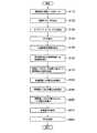
図5は、本実施形態に係る無線基地局100による無線信号RSのSNRの推定動作フロー図である。図5に示すように、ステップS10において、無線基地局100は、無線通信端末200から受信した無線信号RSに含まれるサイクリック・プリフィックスCPを除去する。 FIG. 5 is an operational flowchart of the SNR estimation of the radio signal RS by the
ステップS20において、無線基地局100は、サイクリック・プリフィックスCPが除去された信号系列に対してFFTを実行する。 In step S20, the
ステップS30において、無線基地局100は、Least Square(LS)推定によって、伝搬路推定情報H^[k]を算出する。具体的には、無線基地局100は、(1式)に従って伝搬路推定情報H^[k]を算出する。 In step S30, the
ステップS40において、無線基地局100は、算出した伝搬路推定情報H^[k]、つまり、周波数領域における信号系列から時間領域における信号系列への再変換を実行する。具体的には、無線基地局100は、無線信号RSの伝搬路のインパルス応答h^[i]を算出する。 In step S40, the
ステップS50において、無線基地局100は、インパルス応答h^[i]が含まれる全時間帯Tにおける全電力Wを算出する。 In step S50, the
ステップS60において、無線基地局100は、時間帯tnにおける電力Naを算出する。 In step S60, the
ステップS70において、無線基地局100は、時間帯tnにおける電力Naに基づいて、ノイズ電力Nを算出する。 In step S70, the
具体的には、無線基地局100は、(5式)に基づいて、全電力W及び電力Naを算出する。また、無線基地局100は、Na/(1-CP/100)によってノイズ電力Nを算出する。 Specifically, the
ステップS80において、無線基地局100は、無線信号RSの信号電力を算出する。具体的には、無線基地局100は、(6式)に示すように、全電力Wから電力Naを減算することによって、信号電力を算出する。 In step S80, the
ステップS90において、無線基地局100は、算出した信号電力及び電力Naを用いてSNRを推定する。具体的には、無線基地局100は、(6式)を用いて無線信号RSのSNRを算出する。 In step S90, the
(4)作用・効果
無線基地局100によれば、無線信号RSのSNRは、周波数領域ではなく時間領域における信号系列S3、具体的には、インパルス応答h^[i]に基づいて推定される。このため、シンボル当たりの時間が長く、広帯域を占有する無線通信システム、特に、マルチキャリア方式を用いる無線通信システム1でも、SNRの推定精度が低下することを抑制できる。(4) Operation / Effect According to the
すなわち、無線基地局100によれば、既知シンボルSP(プリアンブル)に基づいて無線信号RSのSNRを推定する場合において、より正確にSNRを推定できる。That is, according to the
本実施形態では、ガードインターバルの時間長、具体的には、サイクリック・プリフィックス長LCPに基づいて、時間帯tsと時間帯tnとの分割位置D1が決定される。一般的に、振幅が所定の閾値を超えるインパルス応答h^[i]は、サイクリック・プリフィックス長LCP内に収まることが多いため、複雑な演算をすることなく、時間帯tsと時間帯tnとの分割位置D1を決定することができる。In the present embodiment, the division position D1 between the time zone ts and the time zone tn is determined based on the time length of the guard interval, specifically, the cyclic prefix length LCP . In general, an impulse response h ^ [i] whose amplitude exceeds a predetermined threshold often falls within the cyclic prefix length LCP , and therefore, the time zone ts and the time zone tn are not complicatedly calculated. Can be determined.
[第2実施形態]
次に、本発明の第2実施形態について説明する。本実施形態では、インパルス応答h^[i]の振幅が所定の閾値を超える信号成分を含む時間帯tsと、雑音成分が支配的である時間帯tnとの分割位置D1を、無線信号RSのマルチパスの状態などに応じて、動的に変化させる。[Second Embodiment]
Next, a second embodiment of the present invention will be described. In the present embodiment, the division position D1 between the time zone ts including the signal component in which the amplitude of the impulse response h ^ [i] exceeds a predetermined threshold and the time zone tn in which the noise component is dominant is represented by the radio signal RS. It is dynamically changed according to the multipath status.
すなわち、実際の環境においては、無線信号RSの遅延波の到来時間がサイクリック・プリフィックス長LCPと同程度の時間になるとは限らず、図9(a)に示すようにサイクリック・プリフィックス長LCPよりも短い時間に集中したり、図9(b)に示すようにサイクリック・プリフィックス長LCPを超える遅延波が存在したりする場合がある。そこで、本実施形態では、当該遅延波の到来タイミング(受信タイミング)に基づいて、時間帯tsと時間帯tnとの分割位置D1(図8参照)を変化させることによって、雑音電力の推定精度を向上させる。例えば、遅延波の到来時間がサイクリック・プリフィックス長LCPよりも短い場合、時間帯tnを増やすことによって雑音電力の推定精度を向上させる。That is, in an actual environment, the arrival time of the delayed wave of the radio signal RS is not always the same as the cyclic prefix length LCP . As shown in FIG. L or concentrated in a shorter time than theCP, there is a case where a delayed wave exceeding a cyclic prefix length LCP as shown in FIG. 9 (b) or present. Therefore, in the present embodiment, the estimation accuracy of the noise power is improved by changing the division position D1 (see FIG. 8) between the time zone ts and the time zone tn based on the arrival timing (reception timing) of the delayed wave. Improve. For example, when the arrival time of the delayed wave is shorter than the cyclic prefix length LCP , the estimation accuracy of the noise power is improved by increasing the time zone tn.
(1)無線通信装置の機能ブロック構成
本実施形態に係る無線基地局100(無線通信装置)の機能ブロック構成は、図2に示した第1実施形態に係る無線基地局100と同様である。ただし、同期処理部110及び時間領域SNR推定部170の機能が一部異なる。なお、以下、第1実施形態と異なる部分について主に説明し、第1実施形態と同様の部分については、説明を適宜省略する。(1) Functional Block Configuration of Radio Communication Device The functional block configuration of the radio base station 100 (radio communication device) according to this embodiment is the same as that of the
図3は、本実施形態に係る同期処理部110の機能ブロック構成図である。また、図4は、本実施形態に係る時間領域SNR推定部170の機能ブロック構成図である。 FIG. 3 is a functional block configuration diagram of the
図3に示すように、本実施形態に係る同期処理部110は、相関ピークサーチ部111及びタイミング決定部113を備える。また、図4に示すように、本実施形態に係る時間領域SNR推定部170は、時間領域分割部171及びSNR算出部173を備える。 As shown in FIG. 3, the
相関ピークサーチ部111は、無線信号RSのマルチパスを検出するために、無線信号RSと既知信号(既知シンボルSP)との相関をとり、相関度が高いピーク部分のサーチを実行する。相関ピークサーチ部111は、当該サーチの実行結果に基づいて、無線基地局100に到来するタイミングが最も遅い遅延波の受信タイミングを測定し、測定した到来タイミングを時間領域分割部171に出力する。In order to detect a multipath of the radio signal RS, the correlation
タイミング決定部113は、無線通信端末200から受信した無線信号RSを構成する信号系列S1の処理タイミングを決定する。 The
時間領域分割部171は、相関ピークサーチ部111から出力された最も遅い遅延波の受信タイミング(latest incoming wave timing)に応じて時間帯tsと時間帯tnとの分割比、つまり、時間帯tsと時間帯tnとの分割位置D1を算出する。具体的には、時間領域分割部171は、(10式)を用いて時間帯tsと時間帯tnとの分割比を算出する。
SNR算出部173は、時間領域分割部171によって算出された時間帯tsと時間帯tnとの分割比、つまり、時間帯tsと時間帯tnとの分割位置D1に基づいて、第1実施形態と同様の方法によって、SNRを算出する。 The
(2)無線通信装置の動作
図6は、本実施形態に係る無線基地局100による無線信号RSのSNRの推定動作フロー図である。図6に示すように、ステップS110において、無線基地局100は、無線信号RSと既知信号(既知シンボルSP)との相関をとり、相関度が高いピーク部分のサーチを実行する。無線基地局100は、当該サーチの実行結果に基づいて無線基地局100に到来するタイミングが最も遅い遅延波の受信タイミングを測定する。(2) Operation of Radio Communication Device FIG. 6 is an operational flowchart for estimating the SNR of the radio signal RS by the
ステップS120において、無線基地局100は、無線信号RSを構成する各サブキャリアに含まれる信号系列S1の処理タイミングを決定する。 In step S120, the
ステップS130〜S160の処理は、第1実施形態に係るステップS10〜S40の処理と同様である。 The process of steps S130 to S160 is the same as the process of steps S10 to S40 according to the first embodiment.
ステップS170において、無線基地局100は、ステップS110におけるピーク部分のサーチ結果に基づいて、時間帯tsの長さを決定する。具体的には、(10式)を用いて、時間帯tsと時間帯tnとの分割比を算出する。 In step S170, the
ステップS180〜S220の処理は、第1実施形態に係るステップS50〜S90の処理と同様である。 The process of steps S180 to S220 is the same as the process of steps S50 to S90 according to the first embodiment.
(3)作用・効果
本実施形態に係る無線基地局100によれば、無線信号RSの遅延波の受信タイミングに基づいて、時間帯tsと時間帯tnとの分割位置D1が決定される。このため、無線信号RSの遅延波がサイクリック・プリフィックス長LCPと同程度の時間とならない場合でも、適切な分割位置D1を設定することができる。すなわち、本実施形態に係る無線基地局100によれば、無線信号RSの遅延波がサイクリック・プリフィックス長LCPと同程度の時間とならない場合でも、正確にSNRを推定できる。(3) Action / Effect According to the
[その他の実施形態]
上述したように、本発明の第1実施形態及び第2実施形態を通じて本発明の内容を開示したが、この開示の一部をなす論述及び図面は、本発明を限定するものであると理解すべきではない。この開示から当業者には様々な代替実施の形態が明らかとなろう。[Other Embodiments]
As described above, the contents of the present invention have been disclosed through the first embodiment and the second embodiment of the present invention. However, it is understood that the description and drawings constituting a part of this disclosure limit the present invention. Should not. From this disclosure, various alternative embodiments will be apparent to those skilled in the art.
例えば、上述した第2実施形態では、無線信号RSの受信品質としてSNRが推定されていたが、SNRに代えて無線信号RSの雑音電力を受信品質として算出してもよい。 For example, in the second embodiment described above, the SNR is estimated as the reception quality of the radio signal RS, but the noise power of the radio signal RS may be calculated as the reception quality instead of the SNR.
具体的には、無線基地局100の時間領域SNR推定部170(雑音電力算出部)は、SNRに代えて、時間帯tnに含まれる信号系列S3(時間領域信号系列)に基づいて、無線信号RSの雑音電力を算出する。 Specifically, the time domain SNR estimation unit 170 (noise power calculation unit) of the
上述した第1実施形態及び第2実施形態では、周波数領域/時間領域変換部160において伝搬路推定情報H^[k]のIFFTが実行されていたが、IFFTに代えて、離散コサイン変換(DCT)などを用いても構わない。 In the first and second embodiments described above, IFFT of the propagation path estimation information H ^ [k] is performed in the frequency domain / time
上述した無線通信システム1では、OFDM方式が採用されていたが、無線通信システム1では、必ずしもOFDM方式が採用されていなくてもよい。また、本発明は、シングルキャリア方式を用いる無線通信システムに適用してもよい。 In the
上述した第1実施形態及び第2実施形態では、無線基地局100が本発明に係る無線通信装置を構成する場合を例として説明したが、無線通信端末200が本発明に係る無線通信装置を構成するようにしても勿論構わない。 In the first embodiment and the second embodiment described above, the case where the
このように、本発明は、ここでは記載していない様々な実施の形態などを含むことは勿論である。したがって、本発明の技術的範囲は、上述の説明から妥当な特許請求の範囲に係る発明特定事項によってのみ定められるものである。 As described above, the present invention naturally includes various embodiments that are not described herein. Therefore, the technical scope of the present invention is defined only by the invention specifying matters according to the scope of claims reasonable from the above description.
1…無線通信システム、100…無線基地局、110…同期処理部、111…相関ピークサーチ部、113…タイミング決定部、120…CP除去部、131…S/P変換部、132…FFT部、133…チャネル等化部、134…P/S変換部、140…復調部、150…チャネル推定部、160…周波数領域/時間領域変換部、170…時間領域SNR推定部、171…時間領域分割部、173…SNR算出部、200…無線通信端末、CP…サイクリック・プリフィックス、D1…分割位置、LCP…サイクリック・プリフィックス長、RS…無線信号、S1〜S3…信号系列、SD…データシンボル、SP…既知シンボル、T…全時間帯、tn,ts…時間帯DESCRIPTION OF
Claims (7)
Translated fromJapanese前記伝搬路推定情報を時間領域における信号系列である時間領域信号系列に再変換する再変換部と、
前記再変換部によって再変換された前記時間領域信号系列が含まれる全時間帯のうち、前記時間領域信号系列の振幅が所定の閾値を超える信号成分を含む第1時間帯と、前記第1時間帯以外の時間帯である第2時間帯とに分割する分割部と、
前記第1時間帯に含まれる前記時間領域信号系列に基づいて、前記無線信号の信号電力を算出するとともに、前記第2時間帯に含まれる前記時間領域信号系列に基づいて、雑音電力を算出することによって、前記無線信号の信号対雑音比を推定するSNR推定部と
を備える無線通信装置。A radio communication device that converts a received radio signal into a signal sequence in a frequency domain and calculates propagation path estimation information that estimates a state of a propagation path of the radio signal based on a known signal included in the radio signal,
A reconverter that reconverts the propagation path estimation information into a time domain signal sequence that is a signal sequence in the time domain;
A first time zone including a signal component in which an amplitude of the time domain signal sequence exceeds a predetermined threshold among all time zones including the time domain signal sequence reconverted by the reconversion unit, and the first time A dividing unit that divides into a second time zone that is a time zone other than the zone;
The signal power of the radio signal is calculated based on the time domain signal sequence included in the first time zone, and the noise power is calculated based on the time domain signal sequence included in the second time zone. Thus, a radio communication apparatus comprising an SNR estimation unit that estimates a signal-to-noise ratio of the radio signal.
前記分割部は、前記ガードインターバルの時間長に基づいて、前記第1時間帯と前記第2時間帯との分割位置を決定する請求項1に記載の無線通信装置。The radio signal is configured according to an orthogonal frequency division multiplexing scheme and includes a guard interval that prevents interference between symbols.
The radio communication apparatus according to claim 1, wherein the division unit determines a division position between the first time zone and the second time zone based on a time length of the guard interval.
前記伝搬路推定情報を時間領域における信号系列である時間領域信号系列に再変換する再変換部と、
前記再変換部によって再変換された前記時間領域信号系列が含まれる時間帯のうち、前記時間領域信号系列の振幅が所定の閾値を超える信号成分を含む第1時間帯と、前記第1時間帯以外の時間帯である第2時間帯とに分割する分割部と、
前記第2時間帯に含まれる前記時間領域信号系列に基づいて、前記無線信号の雑音電力を算出する雑音電力算出部と
を備え、
前記分割部は、前記無線信号のマルチパスの状態に応じて、前記第1時間帯と前記第2時間帯との分割位置を決定する無線通信装置。A radio communication device that converts a received radio signal into a signal sequence in a frequency domain and calculates propagation path estimation information that estimates a state of a propagation path of the radio signal based on a known signal included in the radio signal,
A reconverter that reconverts the propagation path estimation information into a time domain signal sequence that is a signal sequence in the time domain;
A first time zone including a signal component in which an amplitude of the time domain signal sequence exceeds a predetermined threshold among time zones including the time domain signal sequence reconverted by the reconversion unit, and the first time zone A dividing unit that divides into a second time zone that is a time zone other than
A noise power calculation unit that calculates noise power of the radio signal based on the time domain signal sequence included in the second time zone,
The said division part is a radio | wireless communication apparatus which determines the division position of the said 1st time slot | zone and the said 2nd time slot | zone according to the state of the multipath of the said radio signal.
前記伝搬路推定情報を時間領域における信号系列である時間領域信号系列に再変換するステップと、
再変換された前記時間領域信号系列が含まれる全時間帯のうち、前記時間領域信号系列の振幅が所定の閾値を超える信号成分を含む第1時間帯と、前記第1時間帯以外の時間帯である第2時間帯とに分割するステップと、
前記第1時間帯に含まれる前記時間領域信号系列に基づいて、前記無線信号の信号電力を算出するとともに、前記第2時間帯に含まれる前記時間領域信号系列に基づいて、雑音電力を算出することによって、前記無線信号の信号対雑音比を推定するステップと
を備える受信品質推定方法。Receiving quality estimation in a radio communication device that converts a received radio signal into a signal sequence in a frequency domain and calculates propagation path estimation information that estimates a propagation path state of the radio signal based on a known signal included in the radio signal A method,
Reconverting the propagation path estimation information into a time domain signal sequence that is a signal sequence in the time domain;
Of all time zones including the re-converted time domain signal sequence, a first time zone including a signal component in which the amplitude of the time domain signal sequence exceeds a predetermined threshold, and a time zone other than the first time zone Dividing into a second time zone,
The signal power of the radio signal is calculated based on the time domain signal sequence included in the first time zone, and the noise power is calculated based on the time domain signal sequence included in the second time zone. Thereby estimating a signal-to-noise ratio of the radio signal.
前記伝搬路推定情報を時間領域における信号系列である時間領域信号系列に再変換するステップと、
再変換された前記時間領域信号系列が含まれる時間帯のうち、前記時間領域信号系列の振幅が所定の閾値を超える信号成分を含む第1時間帯と、前記第1時間帯以外の時間帯である第2時間帯とに分割するステップと、
前記第2時間帯に含まれる前記時間領域信号系列に基づいて、前記無線信号の雑音電力を算出するステップと
を備え、
前記雑音電力を算出するステップでは、前記無線信号のマルチパスの状態に応じて、前記第1時間帯と前記第2時間帯との分割位置を決定する受信品質推定方法。Receiving quality estimation in a radio communication device that converts a received radio signal into a signal sequence in a frequency domain and calculates propagation path estimation information that estimates a propagation path state of the radio signal based on a known signal included in the radio signal A method,
Reconverting the propagation path estimation information into a time domain signal sequence that is a signal sequence in the time domain;
Among the time zones in which the re-converted time domain signal sequence is included, in a first time zone including a signal component in which the amplitude of the time domain signal sequence exceeds a predetermined threshold, and a time zone other than the first time zone Dividing into a second time zone;
Calculating noise power of the radio signal based on the time domain signal sequence included in the second time zone,
In the step of calculating the noise power, a reception quality estimation method for determining a division position between the first time zone and the second time zone according to a multipath state of the radio signal.
Priority Applications (5)
| Application Number | Priority Date | Filing Date | Title |
|---|---|---|---|
| JP2007256312AJP2009089041A (en) | 2007-09-28 | 2007-09-28 | Wireless communication apparatus and reception quality estimation method |
| US12/680,543US20100266078A1 (en) | 2007-09-28 | 2008-09-25 | Radio communication device, and reception quality estimation method |
| EP08833331.5AEP2194666A4 (en) | 2007-09-28 | 2008-09-25 | RADIO COMMUNICATION DEVICE AND METHOD FOR ESTIMATING RECEPTION QUALITY |
| PCT/JP2008/067353WO2009041542A1 (en) | 2007-09-28 | 2008-09-25 | Radio communication device, and reception quality estimating method |
| CN200880109076.0ACN101809909A (en) | 2007-09-28 | 2008-09-25 | Radio communication device, and reception quality estimating method |
Applications Claiming Priority (1)
| Application Number | Priority Date | Filing Date | Title |
|---|---|---|---|
| JP2007256312AJP2009089041A (en) | 2007-09-28 | 2007-09-28 | Wireless communication apparatus and reception quality estimation method |
Publications (1)
| Publication Number | Publication Date |
|---|---|
| JP2009089041Atrue JP2009089041A (en) | 2009-04-23 |
Family
ID=40661850
Family Applications (1)
| Application Number | Title | Priority Date | Filing Date |
|---|---|---|---|
| JP2007256312AWithdrawnJP2009089041A (en) | 2007-09-28 | 2007-09-28 | Wireless communication apparatus and reception quality estimation method |
Country Status (1)
| Country | Link |
|---|---|
| JP (1) | JP2009089041A (en) |
- 2007
- 2007-09-28JPJP2007256312Apatent/JP2009089041A/ennot_activeWithdrawn
Similar Documents
| Publication | Publication Date | Title |
|---|---|---|
| KR101643419B1 (en) | Method and apparatus for estimating a channel using phase compensation in a wireless communication system | |
| US8064328B2 (en) | Channel estimation device | |
| KR100799539B1 (en) | A Time Synchronization Method Using a Preamble with Good Autocorrelation of Neighbor Sequences in an OPDMA Network and a Frequency Offset Estimation Method Using the Preamble | |
| US8121206B2 (en) | Apparatus and method for estimating delay spread of multi-path fading channel in OFDM system | |
| US10063399B2 (en) | Method and system for adaptive guard interval (GI) combining | |
| KR20100001592A (en) | Method and apparatus for estimating a symbol timing offset in a wireless communication system | |
| US20120328055A1 (en) | Channel estimation circuit, channel estimation method, and receiver | |
| US20100266078A1 (en) | Radio communication device, and reception quality estimation method | |
| JP3754441B1 (en) | Reception method and apparatus, and communication system using the same | |
| JP4157159B1 (en) | Receiving apparatus and receiving method | |
| JP2008227622A (en) | Reception device and communication method | |
| JP4612511B2 (en) | Receiving apparatus and receiving method | |
| US20060198472A1 (en) | Transmission system, transmitter device, and receiver device | |
| JP2009049792A (en) | Receiver and propagation path estimation method | |
| JP5263958B2 (en) | Signal processing device | |
| JP4858199B2 (en) | Radio communication receiving apparatus and receiving method | |
| JP2009089041A (en) | Wireless communication apparatus and reception quality estimation method | |
| KR20130003949A (en) | Methods of estimating timing offset using multi stage for timing synchronization and ofdm reciever | |
| JP5284891B2 (en) | Communication apparatus and delay amount detection method | |
| KR20090119582A (en) | Channel estimation method and apparatus | |
| JP2009088993A (en) | Wireless communication apparatus and reception quality estimation method | |
| JP4812567B2 (en) | Pilot signal allocation method and radio apparatus using the same | |
| JP2008141279A (en) | OFDM receiver | |
| CN108293031B (en) | Transmitter for multicarrier communication | |
| KR101284393B1 (en) | Transmitter for modulating using cyclic delay diversity and receiver for estimating residual frequency offset of ofdm system |
Legal Events
| Date | Code | Title | Description |
|---|---|---|---|
| RD02 | Notification of acceptance of power of attorney | Free format text:JAPANESE INTERMEDIATE CODE: A7422 Effective date:20090930 | |
| RD04 | Notification of resignation of power of attorney | Free format text:JAPANESE INTERMEDIATE CODE: A7424 Effective date:20091015 | |
| A621 | Written request for application examination | Free format text:JAPANESE INTERMEDIATE CODE: A621 Effective date:20100830 | |
| A761 | Written withdrawal of application | Free format text:JAPANESE INTERMEDIATE CODE: A761 Effective date:20110830 |