JP2009082353A - In-vivo indwelling stent and living organ dilator - Google Patents
In-vivo indwelling stent and living organ dilatorDownload PDFInfo
- Publication number
- JP2009082353A JP2009082353AJP2007254731AJP2007254731AJP2009082353AJP 2009082353 AJP2009082353 AJP 2009082353AJP 2007254731 AJP2007254731 AJP 2007254731AJP 2007254731 AJP2007254731 AJP 2007254731AJP 2009082353 AJP2009082353 AJP 2009082353A
- Authority
- JP
- Japan
- Prior art keywords
- stent
- surface side
- base
- side stent
- resin adhesive
- Prior art date
- Legal status (The legal status is an assumption and is not a legal conclusion. Google has not performed a legal analysis and makes no representation as to the accuracy of the status listed.)
- Pending
Links
- 238000001727in vivoMethods0.000titleclaimsabstractdescription43
- 210000000056organAnatomy0.000titleclaimsdescription21
- 239000012790adhesive layerSubstances0.000claimsabstractdescription76
- 229920005989resinPolymers0.000claimsabstractdescription75
- 239000011347resinSubstances0.000claimsabstractdescription75
- 229910052751metalInorganic materials0.000claimsabstractdescription51
- 239000002184metalSubstances0.000claimsabstractdescription51
- 239000013543active substanceSubstances0.000claimsabstractdescription36
- 239000007769metal materialSubstances0.000claimsabstractdescription20
- 239000000758substrateSubstances0.000claimsdescription57
- 229920002988biodegradable polymerPolymers0.000claimsdescription32
- 239000004621biodegradable polymerSubstances0.000claimsdescription32
- 239000010410layerSubstances0.000claimsdescription29
- -1antibioticSubstances0.000claimsdescription20
- 238000004519manufacturing processMethods0.000claimsdescription10
- 239000000126substanceSubstances0.000claimsdescription10
- 239000011148porous materialSubstances0.000claimsdescription9
- 238000003780insertionMethods0.000claimsdescription8
- 230000037431insertionEffects0.000claimsdescription8
- 229940121358tyrosine kinase inhibitorDrugs0.000claimsdescription8
- 239000005541ACE inhibitorSubstances0.000claimsdescription7
- 229940127291Calcium channel antagonistDrugs0.000claimsdescription7
- 229940121710HMGCoA reductase inhibitorDrugs0.000claimsdescription7
- 229940044094angiotensin-converting-enzyme inhibitorDrugs0.000claimsdescription7
- 239000000043antiallergic agentSubstances0.000claimsdescription7
- 239000003146anticoagulant agentSubstances0.000claimsdescription7
- 239000002246antineoplastic agentSubstances0.000claimsdescription7
- 239000003435antirheumatic agentSubstances0.000claimsdescription7
- 239000012620biological materialSubstances0.000claimsdescription7
- 235000021466carotenoidNutrition0.000claimsdescription7
- 150000001747carotenoidsChemical class0.000claimsdescription7
- 229930003935flavonoidNatural products0.000claimsdescription7
- 235000017173flavonoidsNutrition0.000claimsdescription7
- 239000002471hydroxymethylglutaryl coenzyme A reductase inhibitorSubstances0.000claimsdescription7
- 239000003018immunosuppressive agentSubstances0.000claimsdescription7
- 239000005483tyrosine kinase inhibitorSubstances0.000claimsdescription7
- 102000014150InterferonsHuman genes0.000claimsdescription6
- 108010050904InterferonsProteins0.000claimsdescription6
- 239000000853adhesiveSubstances0.000claimsdescription6
- 230000001070adhesive effectEffects0.000claimsdescription6
- 239000005557antagonistSubstances0.000claimsdescription6
- 239000003963antioxidant agentSubstances0.000claimsdescription6
- 229940127218antiplatelet drugDrugs0.000claimsdescription6
- 229960004676antithrombotic agentDrugs0.000claimsdescription6
- 229940079593drugDrugs0.000claimsdescription6
- 239000003814drugSubstances0.000claimsdescription6
- 150000002215flavonoidsChemical class0.000claimsdescription6
- 229940124599anti-inflammatory drugDrugs0.000claimsdescription5
- 239000003524antilipemic agentSubstances0.000claimsdescription5
- 229940125721immunosuppressive agentDrugs0.000claimsdescription5
- 150000002632lipidsChemical class0.000claimsdescription5
- 150000004492retinoid derivativesChemical class0.000claimsdescription5
- 238000003892spreadingMethods0.000claimsdescription5
- 230000007480spreadingEffects0.000claimsdescription5
- 229940122029DNA synthesis inhibitorDrugs0.000claimsdescription4
- 239000003242anti bacterial agentSubstances0.000claimsdescription4
- 229940088710antibiotic agentDrugs0.000claimsdescription4
- 230000000916dilatatory effectEffects0.000claimsdescription4
- 239000003112inhibitorSubstances0.000claimsdescription4
- 102000006495integrinsHuman genes0.000claimsdescription4
- 108010044426integrinsProteins0.000claimsdescription4
- 229940047124interferonsDrugs0.000claimsdescription4
- 229940096701plain lipid modifying drug hmg coa reductase inhibitorsDrugs0.000claimsdescription4
- 239000000106platelet aggregation inhibitorSubstances0.000claimsdescription4
- 150000004917tyrosine kinase inhibitor derivativesChemical class0.000claimsdescription4
- 230000003115biocidal effectEffects0.000claimsdescription3
- 239000000480calcium channel blockerSubstances0.000claimsdescription3
- 238000000354decomposition reactionMethods0.000claimsdescription3
- 239000002344surface layerSubstances0.000claimsdescription3
- 229940125798integrin inhibitorDrugs0.000claimsdescription2
- 229940079322interferonDrugs0.000claimsdescription2
- 239000003865nucleic acid synthesis inhibitorSubstances0.000claimsdescription2
- 208000031481Pathologic ConstrictionDiseases0.000abstractdescription7
- 230000036262stenosisEffects0.000abstractdescription7
- 208000037804stenosisDiseases0.000abstractdescription7
- 230000000306recurrent effectEffects0.000abstract1
- 239000000463materialSubstances0.000description34
- 229910045601alloyInorganic materials0.000description17
- 239000000956alloySubstances0.000description17
- 239000004840adhesive resinSubstances0.000description15
- 229920006223adhesive resinPolymers0.000description15
- 229920001971elastomerPolymers0.000description14
- 239000000806elastomerSubstances0.000description10
- 229920000642polymerPolymers0.000description9
- 208000037803restenosisDiseases0.000description9
- 238000000034methodMethods0.000description7
- 210000004204blood vesselAnatomy0.000description6
- 230000002093peripheral effectEffects0.000description6
- BASFCYQUMIYNBI-UHFFFAOYSA-NplatinumChemical compound[Pt]BASFCYQUMIYNBI-UHFFFAOYSA-N0.000description6
- 229920002379silicone rubberPolymers0.000description6
- 239000004945silicone rubberSubstances0.000description6
- 239000004952PolyamideSubstances0.000description5
- 239000006087Silane Coupling AgentSubstances0.000description5
- 238000011161developmentMethods0.000description5
- 230000018109developmental processEffects0.000description5
- 229920002647polyamidePolymers0.000description5
- AOJJSUZBOXZQNB-TZSSRYMLSA-NDoxorubicinChemical compoundO([C@H]1C[C@@](O)(CC=2C(O)=C3C(=O)C=4C=CC=C(C=4C(=O)C3=C(O)C=21)OC)C(=O)CO)[C@H]1C[C@H](N)[C@H](O)[C@H](C)O1AOJJSUZBOXZQNB-TZSSRYMLSA-N0.000description4
- 239000004698PolyethyleneSubstances0.000description4
- 229910004337Ti-NiInorganic materials0.000description4
- 229910011209Ti—NiInorganic materials0.000description4
- 229910052782aluminiumInorganic materials0.000description4
- 239000002260anti-inflammatory agentSubstances0.000description4
- 238000005452bendingMethods0.000description4
- 230000000975bioactive effectEffects0.000description4
- 239000007822coupling agentSubstances0.000description4
- 239000005038ethylene vinyl acetateSubstances0.000description4
- KHYBPSFKEHXSLX-UHFFFAOYSA-NiminotitaniumChemical compound[Ti]=NKHYBPSFKEHXSLX-UHFFFAOYSA-N0.000description4
- 238000005498polishingMethods0.000description4
- 229920001200poly(ethylene-vinyl acetate)Polymers0.000description4
- 229920000573polyethylenePolymers0.000description4
- 229920000098polyolefinPolymers0.000description4
- 239000004814polyurethaneSubstances0.000description4
- 229920002635polyurethanePolymers0.000description4
- 239000002987primer (paints)Substances0.000description4
- 239000005060rubberSubstances0.000description4
- 229910001220stainless steelInorganic materials0.000description4
- 239000010935stainless steelSubstances0.000description4
- 229920005992thermoplastic resinPolymers0.000description4
- 239000002253acidSubstances0.000description3
- 229940121363anti-inflammatory agentDrugs0.000description3
- 235000006708antioxidantsNutrition0.000description3
- 229920001577copolymerPolymers0.000description3
- 230000006870functionEffects0.000description3
- PCHJSUWPFVWCPO-UHFFFAOYSA-NgoldChemical compound[Au]PCHJSUWPFVWCPO-UHFFFAOYSA-N0.000description3
- 229910052737goldInorganic materials0.000description3
- 239000010931goldSubstances0.000description3
- 238000010438heat treatmentMethods0.000description3
- 229920000126latexPolymers0.000description3
- 239000000203mixtureSubstances0.000description3
- 229910052697platinumInorganic materials0.000description3
- 229920000728polyesterPolymers0.000description3
- 229920000915polyvinyl chloridePolymers0.000description3
- 239000004800polyvinyl chlorideSubstances0.000description3
- 239000000243solutionSubstances0.000description3
- 229940124549vasodilatorDrugs0.000description3
- 239000003071vasodilator agentSubstances0.000description3
- ZGGHKIMDNBDHJB-NRFPMOEYSA-M(3R,5S)-fluvastatin sodiumChemical compound[Na+].C12=CC=CC=C2N(C(C)C)C(\C=C\[C@@H](O)C[C@@H](O)CC([O-])=O)=C1C1=CC=C(F)C=C1ZGGHKIMDNBDHJB-NRFPMOEYSA-M0.000description2
- 102400001368Epidermal growth factorHuman genes0.000description2
- 101800003838Epidermal growth factorProteins0.000description2
- 102000003974Fibroblast growth factor 2Human genes0.000description2
- 108090000379Fibroblast growth factor 2Proteins0.000description2
- 102000003745Hepatocyte Growth FactorHuman genes0.000description2
- 108090000100Hepatocyte Growth FactorProteins0.000description2
- 206010061218InflammationDiseases0.000description2
- FBOZXECLQNJBKD-ZDUSSCGKSA-NL-methotrexateChemical compoundC=1N=C2N=C(N)N=C(N)C2=NC=1CN(C)C1=CC=C(C(=O)N[C@@H](CCC(O)=O)C(O)=O)C=C1FBOZXECLQNJBKD-ZDUSSCGKSA-N0.000description2
- NBIIXXVUZAFLBC-UHFFFAOYSA-NPhosphoric acidChemical compoundOP(O)(O)=ONBIIXXVUZAFLBC-UHFFFAOYSA-N0.000description2
- KMSKQZKKOZQFFG-HSUXVGOQSA-NPirarubicinChemical compoundO([C@H]1[C@@H](N)C[C@@H](O[C@H]1C)O[C@H]1C[C@@](O)(CC=2C(O)=C3C(=O)C=4C=CC=C(C=4C(=O)C3=C(O)C=21)OC)C(=O)CO)[C@H]1CCCCO1KMSKQZKKOZQFFG-HSUXVGOQSA-N0.000description2
- 108010038512Platelet-Derived Growth FactorProteins0.000description2
- 102000010780Platelet-Derived Growth FactorHuman genes0.000description2
- 108010073929Vascular Endothelial Growth Factor AProteins0.000description2
- 102000005789Vascular Endothelial Growth FactorsHuman genes0.000description2
- 108010019530Vascular Endothelial Growth FactorsProteins0.000description2
- 230000002730additional effectEffects0.000description2
- 230000004323axial lengthEffects0.000description2
- 230000015572biosynthetic processEffects0.000description2
- 239000003795chemical substances by applicationSubstances0.000description2
- 229910052804chromiumInorganic materials0.000description2
- 239000011651chromiumSubstances0.000description2
- 238000010586diagramMethods0.000description2
- 230000008034disappearanceEffects0.000description2
- 229940116977epidermal growth factorDrugs0.000description2
- 125000000524functional groupChemical group0.000description2
- 229960003444immunosuppressant agentDrugs0.000description2
- 230000001861immunosuppressant effectEffects0.000description2
- 230000004054inflammatory processEffects0.000description2
- 230000014759maintenance of locationEffects0.000description2
- 229960000485methotrexateDrugs0.000description2
- 229960001221pirarubicinDrugs0.000description2
- 229960002797pitavastatinDrugs0.000description2
- 229920001610polycaprolactonePolymers0.000description2
- 239000004632polycaprolactoneSubstances0.000description2
- 238000012545processingMethods0.000description2
- 238000004904shorteningMethods0.000description2
- 229910052721tungstenInorganic materials0.000description2
- VBEQCZHXXJYVRD-GACYYNSASA-NuroantheloneChemical compoundC([C@@H](C(=O)N[C@H](C(=O)N[C@@H](CS)C(=O)N[C@@H](CC(N)=O)C(=O)N[C@@H](CS)C(=O)N[C@H](C(=O)N[C@@H]([C@@H](C)CC)C(=O)NCC(=O)N[C@@H](CC=1C=CC(O)=CC=1)C(=O)N[C@@H](CO)C(=O)NCC(=O)N[C@@H](CC(O)=O)C(=O)N[C@@H](CCCNC(N)=N)C(=O)N[C@@H](CS)C(=O)N[C@@H](CCC(N)=O)C(=O)N[C@@H]([C@@H](C)O)C(=O)N[C@@H](CCCNC(N)=N)C(=O)N[C@@H](CC(O)=O)C(=O)N[C@@H](CC(C)C)C(=O)N[C@@H](CCCNC(N)=N)C(=O)N[C@@H](CC=1C2=CC=CC=C2NC=1)C(=O)N[C@@H](CC=1C2=CC=CC=C2NC=1)C(=O)N[C@@H](CCC(O)=O)C(=O)N[C@@H](CC(C)C)C(=O)N[C@@H](CCCNC(N)=N)C(O)=O)C(C)C)[C@@H](C)O)NC(=O)[C@H](CO)NC(=O)[C@H](CC(O)=O)NC(=O)[C@H](CC(C)C)NC(=O)[C@H](CO)NC(=O)[C@H](CCC(O)=O)NC(=O)[C@@H](NC(=O)[C@H](CC=1NC=NC=1)NC(=O)[C@H](CCSC)NC(=O)[C@H](CS)NC(=O)[C@@H](NC(=O)CNC(=O)CNC(=O)[C@H](CC(N)=O)NC(=O)[C@H](CC(C)C)NC(=O)[C@H](CS)NC(=O)[C@H](CC=1C=CC(O)=CC=1)NC(=O)CNC(=O)[C@H](CC(O)=O)NC(=O)[C@H](CC=1C=CC(O)=CC=1)NC(=O)[C@H](CO)NC(=O)[C@H](CO)NC(=O)[C@H]1N(CCC1)C(=O)[C@H](CS)NC(=O)CNC(=O)[C@H]1N(CCC1)C(=O)[C@H](CC=1C=CC(O)=CC=1)NC(=O)[C@H](CO)NC(=O)[C@@H](N)CC(N)=O)C(C)C)[C@@H](C)CC)C1=CC=C(O)C=C1VBEQCZHXXJYVRD-GACYYNSASA-N0.000description2
- 230000002792vascularEffects0.000description2
- WMBWREPUVVBILR-WIYYLYMNSA-N(-)-Epigallocatechin-3-o-gallateChemical compoundO([C@@H]1CC2=C(O)C=C(C=C2O[C@@H]1C=1C=C(O)C(O)=C(O)C=1)O)C(=O)C1=CC(O)=C(O)C(O)=C1WMBWREPUVVBILR-WIYYLYMNSA-N0.000description1
- KIUKXJAPPMFGSW-DNGZLQJQSA-N(2S,3S,4S,5R,6R)-6-[(2S,3R,4R,5S,6R)-3-Acetamido-2-[(2S,3S,4R,5R,6R)-6-[(2R,3R,4R,5S,6R)-3-acetamido-2,5-dihydroxy-6-(hydroxymethyl)oxan-4-yl]oxy-2-carboxy-4,5-dihydroxyoxan-3-yl]oxy-5-hydroxy-6-(hydroxymethyl)oxan-4-yl]oxy-3,4,5-trihydroxyoxane-2-carboxylic acidChemical compoundCC(=O)N[C@H]1[C@H](O)O[C@H](CO)[C@@H](O)[C@@H]1O[C@H]1[C@H](O)[C@@H](O)[C@H](O[C@H]2[C@@H]([C@@H](O[C@H]3[C@@H]([C@@H](O)[C@H](O)[C@H](O3)C(O)=O)O)[C@H](O)[C@@H](CO)O2)NC(C)=O)[C@@H](C(O)=O)O1KIUKXJAPPMFGSW-DNGZLQJQSA-N0.000description1
- LJRDOKAZOAKLDU-UDXJMMFXSA-N(2s,3s,4r,5r,6r)-5-amino-2-(aminomethyl)-6-[(2r,3s,4r,5s)-5-[(1r,2r,3s,5r,6s)-3,5-diamino-2-[(2s,3r,4r,5s,6r)-3-amino-4,5-dihydroxy-6-(hydroxymethyl)oxan-2-yl]oxy-6-hydroxycyclohexyl]oxy-4-hydroxy-2-(hydroxymethyl)oxolan-3-yl]oxyoxane-3,4-diol;sulfuric acChemical compoundOS(O)(=O)=O.N[C@@H]1[C@@H](O)[C@H](O)[C@H](CN)O[C@@H]1O[C@H]1[C@@H](O)[C@H](O[C@H]2[C@@H]([C@@H](N)C[C@@H](N)[C@@H]2O)O[C@@H]2[C@@H]([C@@H](O)[C@H](O)[C@@H](CO)O2)N)O[C@@H]1COLJRDOKAZOAKLDU-UDXJMMFXSA-N0.000description1
- NDMPLJNOPCLANR-UHFFFAOYSA-N3,4-dihydroxy-15-(4-hydroxy-18-methoxycarbonyl-5,18-seco-ibogamin-18-yl)-16-methoxy-1-methyl-6,7-didehydro-aspidospermidine-3-carboxylic acid methyl esterNatural productsC1C(CC)(O)CC(CC2(C(=O)OC)C=3C(=CC4=C(C56C(C(C(O)C7(CC)C=CCN(C67)CC5)(O)C(=O)OC)N4C)C=3)OC)CN1CCC1=C2NC2=CC=CC=C12NDMPLJNOPCLANR-UHFFFAOYSA-N0.000description1
- AHYFYQKMYMKPKD-UHFFFAOYSA-N3-ethoxysilylpropan-1-amineChemical compoundCCO[SiH2]CCCNAHYFYQKMYMKPKD-UHFFFAOYSA-N0.000description1
- AOJJSUZBOXZQNB-VTZDEGQISA-N4'-epidoxorubicinChemical compoundO([C@H]1C[C@@](O)(CC=2C(O)=C3C(=O)C=4C=CC=C(C=4C(=O)C3=C(O)C=21)OC)C(=O)CO)[C@H]1C[C@H](N)[C@@H](O)[C@H](C)O1AOJJSUZBOXZQNB-VTZDEGQISA-N0.000description1
- SQDAZGGFXASXDW-UHFFFAOYSA-N5-bromo-2-(trifluoromethoxy)pyridineChemical compoundFC(F)(F)OC1=CC=C(Br)C=N1SQDAZGGFXASXDW-UHFFFAOYSA-N0.000description1
- STQGQHZAVUOBTE-UHFFFAOYSA-N7-Cyan-hept-2t-en-4,6-diinsaeureNatural productsC1=2C(O)=C3C(=O)C=4C(OC)=CC=CC=4C(=O)C3=C(O)C=2CC(O)(C(C)=O)CC1OC1CC(N)C(O)C(C)O1STQGQHZAVUOBTE-UHFFFAOYSA-N0.000description1
- KKJUPNGICOCCDW-UHFFFAOYSA-N7-N,N-Dimethylamino-1,2,3,4,5-pentathiocyclooctaneChemical compoundCN(C)C1CSSSSSC1KKJUPNGICOCCDW-UHFFFAOYSA-N0.000description1
- BSYNRYMUTXBXSQ-UHFFFAOYSA-NAspirinChemical compoundCC(=O)OC1=CC=CC=C1C(O)=OBSYNRYMUTXBXSQ-UHFFFAOYSA-N0.000description1
- XUKUURHRXDUEBC-KAYWLYCHSA-NAtorvastatinChemical compoundC=1C=CC=CC=1C1=C(C=2C=CC(F)=CC=2)N(CC[C@@H](O)C[C@@H](O)CC(O)=O)C(C(C)C)=C1C(=O)NC1=CC=CC=C1XUKUURHRXDUEBC-KAYWLYCHSA-N0.000description1
- XUKUURHRXDUEBC-UHFFFAOYSA-NAtorvastatinNatural productsC=1C=CC=CC=1C1=C(C=2C=CC(F)=CC=2)N(CCC(O)CC(O)CC(O)=O)C(C(C)C)=C1C(=O)NC1=CC=CC=C1XUKUURHRXDUEBC-UHFFFAOYSA-N0.000description1
- 229910001020Au alloyInorganic materials0.000description1
- 239000005528B01AC05 - TiclopidineSubstances0.000description1
- 229920002101ChitinPolymers0.000description1
- 229920001661ChitosanPolymers0.000description1
- 229920001287Chondroitin sulfatePolymers0.000description1
- VYZAMTAEIAYCRO-UHFFFAOYSA-NChromiumChemical compound[Cr]VYZAMTAEIAYCRO-UHFFFAOYSA-N0.000description1
- 108010035532CollagenProteins0.000description1
- 102000008186CollagenHuman genes0.000description1
- 229910017518Cu ZnInorganic materials0.000description1
- 229910017752Cu-ZnInorganic materials0.000description1
- 229910017943Cu—ZnInorganic materials0.000description1
- 229920001651CyanoacrylatePolymers0.000description1
- CMSMOCZEIVJLDB-UHFFFAOYSA-NCyclophosphamideChemical compoundClCCN(CCCl)P1(=O)NCCCO1CMSMOCZEIVJLDB-UHFFFAOYSA-N0.000description1
- PMATZTZNYRCHOR-CGLBZJNRSA-NCyclosporin AChemical compoundCC[C@@H]1NC(=O)[C@H]([C@H](O)[C@H](C)C\C=C\C)N(C)C(=O)[C@H](C(C)C)N(C)C(=O)[C@H](CC(C)C)N(C)C(=O)[C@H](CC(C)C)N(C)C(=O)[C@@H](C)NC(=O)[C@H](C)NC(=O)[C@H](CC(C)C)N(C)C(=O)[C@H](C(C)C)NC(=O)[C@H](CC(C)C)N(C)C(=O)CN(C)C1=OPMATZTZNYRCHOR-CGLBZJNRSA-N0.000description1
- 108010036949CyclosporineProteins0.000description1
- 108010092160DactinomycinProteins0.000description1
- 108010061435EnalaprilProteins0.000description1
- HTIJFSOGRVMCQR-UHFFFAOYSA-NEpirubicinNatural productsCOc1cccc2C(=O)c3c(O)c4CC(O)(CC(OC5CC(N)C(=O)C(C)O5)c4c(O)c3C(=O)c12)C(=O)COHTIJFSOGRVMCQR-UHFFFAOYSA-N0.000description1
- 102100037362FibronectinHuman genes0.000description1
- 108010067306FibronectinsProteins0.000description1
- YCKRFDGAMUMZLT-UHFFFAOYSA-NFluorine atomChemical compound[F]YCKRFDGAMUMZLT-UHFFFAOYSA-N0.000description1
- WMBWREPUVVBILR-UHFFFAOYSA-NGCGNatural productsC=1C(O)=C(O)C(O)=CC=1C1OC2=CC(O)=CC(O)=C2CC1OC(=O)C1=CC(O)=C(O)C(O)=C1WMBWREPUVVBILR-UHFFFAOYSA-N0.000description1
- 108010010803GelatinProteins0.000description1
- 229920002971Heparan sulfatePolymers0.000description1
- HTTJABKRGRZYRN-UHFFFAOYSA-NHeparinChemical compoundOC1C(NC(=O)C)C(O)OC(COS(O)(=O)=O)C1OC1C(OS(O)(=O)=O)C(O)C(OC2C(C(OS(O)(=O)=O)C(OC3C(C(O)C(O)C(O3)C(O)=O)OS(O)(=O)=O)C(CO)O2)NS(O)(=O)=O)C(C(O)=O)O1HTTJABKRGRZYRN-UHFFFAOYSA-N0.000description1
- 102000007625HirudinsHuman genes0.000description1
- 108010007267HirudinsProteins0.000description1
- XDXDZDZNSLXDNA-TZNDIEGXSA-NIdarubicinChemical compoundC1[C@H](N)[C@H](O)[C@H](C)O[C@H]1O[C@@H]1C2=C(O)C(C(=O)C3=CC=CC=C3C3=O)=C3C(O)=C2C[C@@](O)(C(C)=O)C1XDXDZDZNSLXDNA-TZNDIEGXSA-N0.000description1
- XDXDZDZNSLXDNA-UHFFFAOYSA-NIdarubicinNatural productsC1C(N)C(O)C(C)OC1OC1C2=C(O)C(C(=O)C3=CC=CC=C3C3=O)=C3C(O)=C2CC(O)(C(C)=O)C1XDXDZDZNSLXDNA-UHFFFAOYSA-N0.000description1
- 108010085895LamininProteins0.000description1
- 108010007859LisinoprilProteins0.000description1
- UPYKUZBSLRQECL-UKMVMLAPSA-NLycopeneNatural productsCC(=C/C=C/C=C(C)/C=C/C=C(C)/C=C/C1C(=C)CCCC1(C)C)C=CC=C(/C)C=CC2C(=C)CCCC2(C)CUPYKUZBSLRQECL-UKMVMLAPSA-N0.000description1
- JEVVKJMRZMXFBT-XWDZUXABSA-NLycophyllNatural productsOC/C(=C/CC/C(=C\C=C\C(=C/C=C/C(=C\C=C\C=C(/C=C/C=C(\C=C\C=C(/CC/C=C(/CO)\C)\C)/C)\C)/C)\C)/C)/CJEVVKJMRZMXFBT-XWDZUXABSA-N0.000description1
- 229930192392MitomycinNatural products0.000description1
- HZQDCMWJEBCWBR-UUOKFMHZSA-NMizoribineChemical compoundOC1=C(C(=O)N)N=CN1[C@H]1[C@H](O)[C@H](O)[C@@H](CO)O1HZQDCMWJEBCWBR-UUOKFMHZSA-N0.000description1
- PCZOHLXUXFIOCF-UHFFFAOYSA-NMonacolin XNatural productsC12C(OC(=O)C(C)CC)CC(C)C=C2C=CC(C)C1CCC1CC(O)CC(=O)O1PCZOHLXUXFIOCF-UHFFFAOYSA-N0.000description1
- NWIBSHFKIJFRCO-WUDYKRTCSA-NMytomycinChemical compoundC1N2C(C(C(C)=C(N)C3=O)=O)=C3[C@@H](COC(N)=O)[C@@]2(OC)[C@@H]2[C@H]1N2NWIBSHFKIJFRCO-WUDYKRTCSA-N0.000description1
- ZDZOTLJHXYCWBA-VCVYQWHSSA-NN-debenzoyl-N-(tert-butoxycarbonyl)-10-deacetyltaxolChemical compoundO([C@H]1[C@H]2[C@@](C([C@H](O)C3=C(C)[C@@H](OC(=O)[C@H](O)[C@@H](NC(=O)OC(C)(C)C)C=4C=CC=CC=4)C[C@]1(O)C3(C)C)=O)(C)[C@@H](O)C[C@H]1OC[C@]12OC(=O)C)C(=O)C1=CC=CC=C1ZDZOTLJHXYCWBA-VCVYQWHSSA-N0.000description1
- 229910001257Nb alloyInorganic materials0.000description1
- 229910003310Ni-AlInorganic materials0.000description1
- FAIIFDPAEUKBEP-UHFFFAOYSA-NNilvadipineChemical compoundCOC(=O)C1=C(C#N)NC(C)=C(C(=O)OC(C)C)C1C1=CC=CC([N+]([O-])=O)=C1FAIIFDPAEUKBEP-UHFFFAOYSA-N0.000description1
- 229930012538PaclitaxelNatural products0.000description1
- 229910001252Pd alloyInorganic materials0.000description1
- 229920000954PolyglycolidePolymers0.000description1
- 229920001710PolyorthoesterPolymers0.000description1
- 239000004734Polyphenylene sulfideSubstances0.000description1
- 229920000388PolyphosphatePolymers0.000description1
- 239000004743PolypropyleneSubstances0.000description1
- TUZYXOIXSAXUGO-UHFFFAOYSA-NPravastatinNatural productsC1=CC(C)C(CCC(O)CC(O)CC(O)=O)C2C(OC(=O)C(C)CC)CC(O)C=C21TUZYXOIXSAXUGO-UHFFFAOYSA-N0.000description1
- 229910001260Pt alloyInorganic materials0.000description1
- RYMZZMVNJRMUDD-UHFFFAOYSA-NSJ000286063Natural productsC12C(OC(=O)C(C)(C)CC)CC(C)C=C2C=CC(C)C1CCC1CC(O)CC(=O)O1RYMZZMVNJRMUDD-UHFFFAOYSA-N0.000description1
- UCKMPCXJQFINFW-UHFFFAOYSA-NSulphideChemical compound[S-2]UCKMPCXJQFINFW-UHFFFAOYSA-N0.000description1
- 229910001362Ta alloysInorganic materials0.000description1
- QJJXYPPXXYFBGM-LFZNUXCKSA-NTacrolimusChemical compoundC1C[C@@H](O)[C@H](OC)C[C@@H]1\C=C(/C)[C@@H]1[C@H](C)[C@@H](O)CC(=O)[C@H](CC=C)/C=C(C)/C[C@H](C)C[C@H](OC)[C@H]([C@H](C[C@H]2C)OC)O[C@@]2(O)C(=O)C(=O)N2CCCC[C@H]2C(=O)O1QJJXYPPXXYFBGM-LFZNUXCKSA-N0.000description1
- 229910001069Ti alloyInorganic materials0.000description1
- RTAQQCXQSZGOHL-UHFFFAOYSA-NTitaniumChemical compound[Ti]RTAQQCXQSZGOHL-UHFFFAOYSA-N0.000description1
- VXFJYXUZANRPDJ-WTNASJBWSA-NTrandoprilChemical compoundC([C@@H](C(=O)OCC)N[C@@H](C)C(=O)N1[C@@H](C[C@H]2CCCC[C@@H]21)C(O)=O)CC1=CC=CC=C1VXFJYXUZANRPDJ-WTNASJBWSA-N0.000description1
- 206010072810Vascular wall hypertrophyDiseases0.000description1
- JXLYSJRDGCGARV-WWYNWVTFSA-NVinblastineNatural productsO=C(O[C@H]1[C@](O)(C(=O)OC)[C@@H]2N(C)c3c(cc(c(OC)c3)[C@]3(C(=O)OC)c4[nH]c5c(c4CCN4C[C@](O)(CC)C[C@H](C3)C4)cccc5)[C@@]32[C@H]2[C@@]1(CC)C=CCN2CC3)CJXLYSJRDGCGARV-WWYNWVTFSA-N0.000description1
- 102100035140VitronectinHuman genes0.000description1
- 108010031318VitronectinProteins0.000description1
- WAIPAZQMEIHHTJ-UHFFFAOYSA-N[Cr].[Co]Chemical class[Cr].[Co]WAIPAZQMEIHHTJ-UHFFFAOYSA-N0.000description1
- 229960001138acetylsalicylic acidDrugs0.000description1
- USZYSDMBJDPRIF-SVEJIMAYSA-Naclacinomycin AChemical compoundO([C@H]1[C@@H](O)C[C@@H](O[C@H]1C)O[C@H]1[C@H](C[C@@H](O[C@H]1C)O[C@H]1C[C@]([C@@H](C2=CC=3C(=O)C4=CC=CC(O)=C4C(=O)C=3C(O)=C21)C(=O)OC)(O)CC)N(C)C)[C@H]1CCC(=O)[C@H](C)O1USZYSDMBJDPRIF-SVEJIMAYSA-N0.000description1
- 229960004176aclarubicinDrugs0.000description1
- 229930183665actinomycinNatural products0.000description1
- 229940009456adriamycinDrugs0.000description1
- 125000003545alkoxy groupChemical group0.000description1
- OENHQHLEOONYIE-UKMVMLAPSA-Nall-trans beta-caroteneNatural productsCC=1CCCC(C)(C)C=1/C=C/C(/C)=C/C=C/C(/C)=C/C=C/C=C(C)C=CC=C(C)C=CC1=C(C)CCCC1(C)COENHQHLEOONYIE-UKMVMLAPSA-N0.000description1
- 150000001370alpha-amino acid derivativesChemical class0.000description1
- 235000008206alpha-amino acidsNutrition0.000description1
- XAGFODPZIPBFFR-UHFFFAOYSA-NaluminiumChemical compound[Al]XAGFODPZIPBFFR-UHFFFAOYSA-N0.000description1
- 229910000147aluminium phosphateInorganic materials0.000description1
- 125000003277amino groupChemical group0.000description1
- 235000010208anthocyaninNutrition0.000description1
- 239000004410anthocyaninSubstances0.000description1
- 229930002877anthocyaninNatural products0.000description1
- 150000004636anthocyaninsChemical class0.000description1
- 230000001315anti-hyperlipaemic effectEffects0.000description1
- 229940030600antihypertensive agentDrugs0.000description1
- 239000002220antihypertensive agentSubstances0.000description1
- 230000003078antioxidant effectEffects0.000description1
- 239000004019antithrombinSubstances0.000description1
- 229940127217antithrombotic drugDrugs0.000description1
- 229960005370atorvastatinDrugs0.000description1
- 229960002170azathioprineDrugs0.000description1
- LMEKQMALGUDUQG-UHFFFAOYSA-NazathioprineChemical compoundCN1C=NC([N+]([O-])=O)=C1SC1=NC=NC2=C1NC=N2LMEKQMALGUDUQG-UHFFFAOYSA-N0.000description1
- QZVNQOLPLYWLHQ-ZEQKJWHPSA-NbenidipineChemical compoundC1([C@H]2C(=C(C)NC(C)=C2C(=O)OC)C(=O)O[C@H]2CN(CC=3C=CC=CC=3)CCC2)=CC=CC([N+]([O-])=O)=C1QZVNQOLPLYWLHQ-ZEQKJWHPSA-N0.000description1
- 229960004916benidipineDrugs0.000description1
- 235000013734beta-caroteneNutrition0.000description1
- 239000011648beta-caroteneSubstances0.000description1
- TUPZEYHYWIEDIH-WAIFQNFQSA-Nbeta-caroteneNatural productsCC(=C/C=C/C=C(C)/C=C/C=C(C)/C=C/C1=C(C)CCCC1(C)C)C=CC=C(/C)C=CC2=CCCCC2(C)CTUPZEYHYWIEDIH-WAIFQNFQSA-N0.000description1
- 229960002747betacaroteneDrugs0.000description1
- 210000000013bile ductAnatomy0.000description1
- 238000006065biodegradation reactionMethods0.000description1
- 230000036760body temperatureEffects0.000description1
- 229910052796boronInorganic materials0.000description1
- DQXBYHZEEUGOBF-UHFFFAOYSA-Nbut-3-enoic acid;etheneChemical compoundC=C.OC(=O)CC=CDQXBYHZEEUGOBF-UHFFFAOYSA-N0.000description1
- 229960000830captoprilDrugs0.000description1
- FAKRSMQSSFJEIM-RQJHMYQMSA-NcaptoprilChemical compoundSC[C@@H](C)C(=O)N1CCC[C@H]1C(O)=OFAKRSMQSSFJEIM-RQJHMYQMSA-N0.000description1
- 150000001765catechinChemical class0.000description1
- ADRVNXBAWSRFAJ-UHFFFAOYSA-NcatechinNatural productsOC1Cc2cc(O)cc(O)c2OC1c3ccc(O)c(O)c3ADRVNXBAWSRFAJ-UHFFFAOYSA-N0.000description1
- 235000005487catechinNutrition0.000description1
- 229960005110cerivastatinDrugs0.000description1
- SEERZIQQUAZTOL-ANMDKAQQSA-NcerivastatinChemical compoundCOCC1=C(C(C)C)N=C(C(C)C)C(\C=C\[C@@H](O)C[C@@H](O)CC(O)=O)=C1C1=CC=C(F)C=C1SEERZIQQUAZTOL-ANMDKAQQSA-N0.000description1
- GPUADMRJQVPIAS-QCVDVZFFSA-Mcerivastatin sodiumChemical compound[Na+].COCC1=C(C(C)C)N=C(C(C)C)C(\C=C\[C@@H](O)C[C@@H](O)CC([O-])=O)=C1C1=CC=C(F)C=C1GPUADMRJQVPIAS-QCVDVZFFSA-M0.000description1
- 229940052311cerivastatin sodiumDrugs0.000description1
- 230000008859changeEffects0.000description1
- 238000003486chemical etchingMethods0.000description1
- 229940059329chondroitin sulfateDrugs0.000description1
- 229960001265ciclosporinDrugs0.000description1
- 229960005025cilazaprilDrugs0.000description1
- HHHKFGXWKKUNCY-FHWLQOOXSA-NcilazaprilChemical compoundC([C@@H](C(=O)OCC)N[C@@H]1C(N2[C@@H](CCCN2CCC1)C(O)=O)=O)CC1=CC=CC=C1HHHKFGXWKKUNCY-FHWLQOOXSA-N0.000description1
- 239000011248coating agentSubstances0.000description1
- 238000000576coating methodMethods0.000description1
- 229910017052cobaltInorganic materials0.000description1
- 239000010941cobaltSubstances0.000description1
- GUTLYIVDDKVIGB-UHFFFAOYSA-Ncobalt atomChemical compound[Co]GUTLYIVDDKVIGB-UHFFFAOYSA-N0.000description1
- 229920001436collagenPolymers0.000description1
- 229920002770condensed tanninPolymers0.000description1
- 239000000470constituentSubstances0.000description1
- 229910052802copperInorganic materials0.000description1
- TVZPLCNGKSPOJA-UHFFFAOYSA-Ncopper zincChemical compound[Cu].[Zn]TVZPLCNGKSPOJA-UHFFFAOYSA-N0.000description1
- 230000007797corrosionEffects0.000description1
- 238000005260corrosionMethods0.000description1
- 238000001723curingMethods0.000description1
- 238000005520cutting processMethods0.000description1
- NLCKLZIHJQEMCU-UHFFFAOYSA-Ncyano prop-2-enoateChemical classC=CC(=O)OC#NNLCKLZIHJQEMCU-UHFFFAOYSA-N0.000description1
- 229960004397cyclophosphamideDrugs0.000description1
- 229930182912cyclosporinNatural products0.000description1
- 229960000975daunorubicinDrugs0.000description1
- STQGQHZAVUOBTE-VGBVRHCVSA-NdaunorubicinChemical compoundO([C@H]1C[C@@](O)(CC=2C(O)=C3C(=O)C=4C=CC=C(C=4C(=O)C3=C(O)C=21)OC)C(C)=O)[C@H]1C[C@H](N)[C@H](O)[C@H](C)O1STQGQHZAVUOBTE-VGBVRHCVSA-N0.000description1
- 239000007857degradation productSubstances0.000description1
- 229960005227delaprilDrugs0.000description1
- WOUOLAUOZXOLJQ-MBSDFSHPSA-NdelaprilChemical compoundC([C@@H](C(=O)OCC)N[C@@H](C)C(=O)N(CC(O)=O)C1CC2=CC=CC=C2C1)CC1=CC=CC=C1WOUOLAUOZXOLJQ-MBSDFSHPSA-N0.000description1
- 229960003957dexamethasoneDrugs0.000description1
- UREBDLICKHMUKA-CXSFZGCWSA-NdexamethasoneChemical compoundC1CC2=CC(=O)C=C[C@]2(C)[C@]2(F)[C@@H]1[C@@H]1C[C@@H](C)[C@@](C(=O)CO)(O)[C@@]1(C)C[C@@H]2OUREBDLICKHMUKA-CXSFZGCWSA-N0.000description1
- HSUGRBWQSSZJOP-RTWAWAEBSA-NdiltiazemChemical compoundC1=CC(OC)=CC=C1[C@H]1[C@@H](OC(C)=O)C(=O)N(CCN(C)C)C2=CC=CC=C2S1HSUGRBWQSSZJOP-RTWAWAEBSA-N0.000description1
- 229960004166diltiazemDrugs0.000description1
- WHGNXNCOTZPEEK-UHFFFAOYSA-Ndimethoxy-methyl-[3-(oxiran-2-ylmethoxy)propyl]silaneChemical compoundCO[Si](C)(OC)CCCOCC1CO1WHGNXNCOTZPEEK-UHFFFAOYSA-N0.000description1
- 201000010099diseaseDiseases0.000description1
- 208000037265diseases, disorders, signs and symptomsDiseases0.000description1
- VZFDRQUWHOVFCA-UHFFFAOYSA-Ldisodium;2-sulfanylbutanedioateChemical compound[Na+].[Na+].[O-]C(=O)CC(S)C([O-])=OVZFDRQUWHOVFCA-UHFFFAOYSA-L0.000description1
- 229960003668docetaxelDrugs0.000description1
- 229960004679doxorubicinDrugs0.000description1
- 230000000694effectsEffects0.000description1
- 238000009760electrical discharge machiningMethods0.000description1
- OYFJQPXVCSSHAI-QFPUQLAESA-Nenalapril maleateChemical compoundOC(=O)\C=C/C(O)=O.C([C@@H](C(=O)OCC)N[C@@H](C)C(=O)N1[C@@H](CCC1)C(O)=O)CC1=CC=CC=C1OYFJQPXVCSSHAI-QFPUQLAESA-N0.000description1
- 229960000309enalapril maleateDrugs0.000description1
- 229940030275epigallocatechin gallateDrugs0.000description1
- 229960001904epirubicinDrugs0.000description1
- 210000002919epithelial cellAnatomy0.000description1
- 125000003700epoxy groupChemical group0.000description1
- 210000003238esophagusAnatomy0.000description1
- 150000002148estersChemical class0.000description1
- 239000003925fatSubstances0.000description1
- 239000012530fluidSubstances0.000description1
- 239000011737fluorineSubstances0.000description1
- 229910052731fluorineInorganic materials0.000description1
- 229960003765fluvastatinDrugs0.000description1
- 229960000868fluvastatin sodiumDrugs0.000description1
- 230000004927fusionEffects0.000description1
- 229910052733galliumInorganic materials0.000description1
- 229920000159gelatinPolymers0.000description1
- 239000008273gelatinSubstances0.000description1
- 235000019322gelatineNutrition0.000description1
- 235000011852gelatine dessertsNutrition0.000description1
- 238000010353genetic engineeringMethods0.000description1
- 229940045109genisteinDrugs0.000description1
- 235000006539genisteinNutrition0.000description1
- TZBJGXHYKVUXJN-UHFFFAOYSA-NgenisteinNatural productsC1=CC(O)=CC=C1C1=COC2=CC(O)=CC(O)=C2C1=OTZBJGXHYKVUXJN-UHFFFAOYSA-N0.000description1
- ZCOLJUOHXJRHDI-CMWLGVBASA-Ngenistein 7-O-beta-D-glucosideChemical compoundO[C@@H]1[C@@H](O)[C@H](O)[C@@H](CO)O[C@H]1OC1=CC(O)=C2C(=O)C(C=3C=CC(O)=CC=3)=COC2=C1ZCOLJUOHXJRHDI-CMWLGVBASA-N0.000description1
- 239000003353gold alloySubstances0.000description1
- 238000009499grossingMethods0.000description1
- 239000003966growth inhibitorSubstances0.000description1
- 229960002706gusperimusDrugs0.000description1
- IDINUJSAMVOPCM-UHFFFAOYSA-NgusperimusChemical compoundNCCCNCCCCNC(=O)C(O)NC(=O)CCCCCCN=C(N)NIDINUJSAMVOPCM-UHFFFAOYSA-N0.000description1
- 229960002897heparinDrugs0.000description1
- 229920000669heparinPolymers0.000description1
- WQPDUTSPKFMPDP-OUMQNGNKSA-NhirudinChemical compoundC([C@@H](C(=O)N[C@@H](CCC(O)=O)C(=O)N[C@@H](CCC(O)=O)C(=O)N[C@@H]([C@@H](C)CC)C(=O)N1[C@@H](CCC1)C(=O)N[C@@H](CCC(O)=O)C(=O)N[C@@H](CCC(O)=O)C(=O)N[C@@H](CC=1C=CC(OS(O)(=O)=O)=CC=1)C(=O)N[C@@H](CC(C)C)C(=O)N[C@@H](CCC(N)=O)C(O)=O)NC(=O)[C@H](CC(O)=O)NC(=O)CNC(=O)[C@H](CC(O)=O)NC(=O)[C@H](CC(N)=O)NC(=O)[C@H](CC=1NC=NC=1)NC(=O)[C@H](CO)NC(=O)[C@H](CCC(N)=O)NC(=O)[C@H]1N(CCC1)C(=O)[C@H](CCCCN)NC(=O)[C@H]1N(CCC1)C(=O)[C@@H](NC(=O)CNC(=O)[C@H](CCC(O)=O)NC(=O)CNC(=O)[C@@H](NC(=O)[C@@H](NC(=O)[C@H]1NC(=O)[C@H](CCC(N)=O)NC(=O)[C@H](CC(N)=O)NC(=O)[C@H](CCCCN)NC(=O)[C@H](CCC(O)=O)NC(=O)CNC(=O)[C@H](CC(O)=O)NC(=O)[C@H](CO)NC(=O)CNC(=O)[C@H](CC(C)C)NC(=O)[C@H]([C@@H](C)CC)NC(=O)[C@@H]2CSSC[C@@H](C(=O)N[C@@H](CCC(O)=O)C(=O)NCC(=O)N[C@@H](CO)C(=O)N[C@@H](CC(N)=O)C(=O)N[C@H](C(=O)N[C@H](C(NCC(=O)N[C@@H](CCC(N)=O)C(=O)NCC(=O)N[C@@H](CC(N)=O)C(=O)N[C@@H](CCCCN)C(=O)N2)=O)CSSC1)C(C)C)NC(=O)[C@H](CC(C)C)NC(=O)[C@H]1NC(=O)[C@H](CC(C)C)NC(=O)[C@H](CC(N)=O)NC(=O)[C@H](CCC(N)=O)NC(=O)CNC(=O)[C@H](CO)NC(=O)[C@H](CCC(O)=O)NC(=O)[C@H]([C@@H](C)O)NC(=O)[C@@H](NC(=O)[C@H](CC(O)=O)NC(=O)[C@@H](NC(=O)[C@H](CC=2C=CC(O)=CC=2)NC(=O)[C@@H](NC(=O)[C@@H](N)C(C)C)C(C)C)[C@@H](C)O)CSSC1)C(C)C)[C@@H](C)O)[C@@H](C)O)C1=CC=CC=C1WQPDUTSPKFMPDP-OUMQNGNKSA-N0.000description1
- 229940006607hirudinDrugs0.000description1
- 229920002674hyaluronanPolymers0.000description1
- 229960003160hyaluronic acidDrugs0.000description1
- 229960000908idarubicinDrugs0.000description1
- 238000002347injectionMethods0.000description1
- 239000007924injectionSubstances0.000description1
- 229960004768irinotecanDrugs0.000description1
- UWKQSNNFCGGAFS-XIFFEERXSA-NirinotecanChemical compoundC1=C2C(CC)=C3CN(C(C4=C([C@@](C(=O)OC4)(O)CC)C=4)=O)C=4C3=NC2=CC=C1OC(=O)N(CC1)CCC1N1CCCCC1UWKQSNNFCGGAFS-XIFFEERXSA-N0.000description1
- 229910052742ironInorganic materials0.000description1
- 238000003698laser cuttingMethods0.000description1
- 229910052745leadInorganic materials0.000description1
- 229960002394lisinoprilDrugs0.000description1
- RLAWWYSOJDYHDC-BZSNNMDCSA-NlisinoprilChemical compoundC([C@H](N[C@@H](CCCCN)C(=O)N1[C@@H](CCC1)C(O)=O)C(O)=O)CC1=CC=CC=C1RLAWWYSOJDYHDC-BZSNNMDCSA-N0.000description1
- 238000011068loading methodMethods0.000description1
- 229960004844lovastatinDrugs0.000description1
- PCZOHLXUXFIOCF-BXMDZJJMSA-NlovastatinChemical compoundC([C@H]1[C@@H](C)C=CC2=C[C@H](C)C[C@@H]([C@H]12)OC(=O)[C@@H](C)CC)C[C@@H]1C[C@@H](O)CC(=O)O1PCZOHLXUXFIOCF-BXMDZJJMSA-N0.000description1
- QLJODMDSTUBWDW-UHFFFAOYSA-Nlovastatin hydroxy acidNatural productsC1=CC(C)C(CCC(O)CC(O)CC(O)=O)C2C(OC(=O)C(C)CC)CC(C)C=C21QLJODMDSTUBWDW-UHFFFAOYSA-N0.000description1
- 238000013035low temperature curingMethods0.000description1
- 235000012661lycopeneNutrition0.000description1
- 239000001751lycopeneSubstances0.000description1
- 229960004999lycopeneDrugs0.000description1
- OAIJSZIZWZSQBC-GYZMGTAESA-NlycopeneChemical compoundCC(C)=CCC\C(C)=C\C=C\C(\C)=C\C=C\C(\C)=C\C=C\C=C(/C)\C=C\C=C(/C)\C=C\C=C(/C)CCC=C(C)COAIJSZIZWZSQBC-GYZMGTAESA-N0.000description1
- 229910052748manganeseInorganic materials0.000description1
- 230000000873masking effectEffects0.000description1
- VKQFCGNPDRICFG-UHFFFAOYSA-Nmethyl 2-methylpropyl 2,6-dimethyl-4-(2-nitrophenyl)-1,4-dihydropyridine-3,5-dicarboxylateChemical compoundCOC(=O)C1=C(C)NC(C)=C(C(=O)OCC(C)C)C1C1=CC=CC=C1[N+]([O-])=OVKQFCGNPDRICFG-UHFFFAOYSA-N0.000description1
- 230000005012migrationEffects0.000description1
- 238000013508migrationMethods0.000description1
- 229960004857mitomycinDrugs0.000description1
- 229950000844mizoribineDrugs0.000description1
- 230000037257muscle growthEffects0.000description1
- 229960004866mycophenolate mofetilDrugs0.000description1
- RTGDFNSFWBGLEC-SYZQJQIISA-Nmycophenolate mofetilChemical compoundCOC1=C(C)C=2COC(=O)C=2C(O)=C1C\C=C(/C)CCC(=O)OCCN1CCOCC1RTGDFNSFWBGLEC-SYZQJQIISA-N0.000description1
- 229910052759nickelInorganic materials0.000description1
- HYIMSNHJOBLJNT-UHFFFAOYSA-NnifedipineChemical compoundCOC(=O)C1=C(C)NC(C)=C(C(=O)OC)C1C1=CC=CC=C1[N+]([O-])=OHYIMSNHJOBLJNT-UHFFFAOYSA-N0.000description1
- 229960001597nifedipineDrugs0.000description1
- 229960005366nilvadipineDrugs0.000description1
- 229910052758niobiumInorganic materials0.000description1
- 239000010955niobiumSubstances0.000description1
- 229960000227nisoldipineDrugs0.000description1
- 229960001592paclitaxelDrugs0.000description1
- SWELZOZIOHGSPA-UHFFFAOYSA-Npalladium silverChemical compound[Pd].[Ag]SWELZOZIOHGSPA-UHFFFAOYSA-N0.000description1
- 229960001639penicillamineDrugs0.000description1
- 229960003929perindopril erbumineDrugs0.000description1
- IYNMDWMQHSMDDE-MHXJNQAMSA-Nperindopril erbumineChemical compoundCC(C)(C)N.C1CCC[C@@H]2N(C(=O)[C@H](C)N[C@@H](CCC)C(=O)OCC)[C@H](C(O)=O)C[C@@H]21IYNMDWMQHSMDDE-MHXJNQAMSA-N0.000description1
- VGYFMXBACGZSIL-MCBHFWOFSA-NpitavastatinChemical compoundOC(=O)C[C@H](O)C[C@H](O)\C=C\C1=C(C2CC2)N=C2C=CC=CC2=C1C1=CC=C(F)C=C1VGYFMXBACGZSIL-MCBHFWOFSA-N0.000description1
- RHGYHLPFVJEAOC-FFNUKLMVSA-Lpitavastatin calciumChemical compound[Ca+2].[O-]C(=O)C[C@H](O)C[C@H](O)\C=C\C1=C(C2CC2)N=C2C=CC=CC2=C1C1=CC=C(F)C=C1.[O-]C(=O)C[C@H](O)C[C@H](O)\C=C\C1=C(C2CC2)N=C2C=CC=CC2=C1C1=CC=C(F)C=C1RHGYHLPFVJEAOC-FFNUKLMVSA-L0.000description1
- 229920003023plasticPolymers0.000description1
- 239000004033plasticSubstances0.000description1
- 238000007747platingMethods0.000description1
- 229920000747poly(lactic acid)Polymers0.000description1
- 239000002745poly(ortho ester)Substances0.000description1
- 229920002627poly(phosphazenes)Polymers0.000description1
- 229920002492poly(sulfone)Polymers0.000description1
- 229920001230polyarylatePolymers0.000description1
- 229920000412polyarylenePolymers0.000description1
- 239000004417polycarbonateSubstances0.000description1
- 229920000515polycarbonatePolymers0.000description1
- 229920000139polyethylene terephthalatePolymers0.000description1
- 239000005020polyethylene terephthalateSubstances0.000description1
- 229920000151polyglycolPolymers0.000description1
- 239000010695polyglycolSubstances0.000description1
- 239000004633polyglycolic acidSubstances0.000description1
- 239000004626polylactic acidSubstances0.000description1
- 229920006124polyolefin elastomerPolymers0.000description1
- 229920001184polypeptidePolymers0.000description1
- 229920000069polyphenylene sulfidePolymers0.000description1
- 239000001205polyphosphateSubstances0.000description1
- 235000011176polyphosphatesNutrition0.000description1
- 229920001155polypropylenePolymers0.000description1
- 229920003225polyurethane elastomerPolymers0.000description1
- 229960002965pravastatinDrugs0.000description1
- TUZYXOIXSAXUGO-PZAWKZKUSA-NpravastatinChemical compoundC1=C[C@H](C)[C@H](CC[C@@H](O)C[C@@H](O)CC(O)=O)[C@H]2[C@@H](OC(=O)[C@@H](C)CC)C[C@H](O)C=C21TUZYXOIXSAXUGO-PZAWKZKUSA-N0.000description1
- 239000010970precious metalSubstances0.000description1
- 229960005205prednisoloneDrugs0.000description1
- OIGNJSKKLXVSLS-VWUMJDOOSA-NprednisoloneChemical compoundO=C1C=C[C@]2(C)[C@H]3[C@@H](O)C[C@](C)([C@@](CC4)(O)C(=O)CO)[C@@H]4[C@@H]3CCC2=C1OIGNJSKKLXVSLS-VWUMJDOOSA-N0.000description1
- 238000002360preparation methodMethods0.000description1
- FYPMFJGVHOHGLL-UHFFFAOYSA-NprobucolChemical compoundC=1C(C(C)(C)C)=C(O)C(C(C)(C)C)=CC=1SC(C)(C)SC1=CC(C(C)(C)C)=C(O)C(C(C)(C)C)=C1FYPMFJGVHOHGLL-UHFFFAOYSA-N0.000description1
- 229960003912probucolDrugs0.000description1
- 102000004196processed proteins & peptidesHuman genes0.000description1
- 108090000765processed proteins & peptidesProteins0.000description1
- 230000001737promoting effectEffects0.000description1
- 229960001455quinaprilDrugs0.000description1
- JSDRRTOADPPCHY-HSQYWUDLSA-NquinaprilChemical compoundC([C@@H](C(=O)OCC)N[C@@H](C)C(=O)N1[C@@H](CC2=CC=CC=C2C1)C(O)=O)CC1=CC=CC=C1JSDRRTOADPPCHY-HSQYWUDLSA-N0.000description1
- ZAHRKKWIAAJSAO-UHFFFAOYSA-NrapamycinNatural productsCOCC(O)C(=C/C(C)C(=O)CC(OC(=O)C1CCCCN1C(=O)C(=O)C2(O)OC(CC(OC)C(=CC=CC=CC(C)CC(C)C(=O)C)C)CCC2C)C(C)CC3CCC(O)C(C3)OC)CZAHRKKWIAAJSAO-UHFFFAOYSA-N0.000description1
- 239000002994raw materialSubstances0.000description1
- 229930002330retinoic acidNatural products0.000description1
- 229910001285shape-memory alloyInorganic materials0.000description1
- 125000005372silanol groupChemical group0.000description1
- 229910052710siliconInorganic materials0.000description1
- 229960002855simvastatinDrugs0.000description1
- RYMZZMVNJRMUDD-HGQWONQESA-NsimvastatinChemical compoundC([C@H]1[C@@H](C)C=CC2=C[C@H](C)C[C@@H]([C@H]12)OC(=O)C(C)(C)CC)C[C@@H]1C[C@@H](O)CC(=O)O1RYMZZMVNJRMUDD-HGQWONQESA-N0.000description1
- 229960002930sirolimusDrugs0.000description1
- QFJCIRLUMZQUOT-HPLJOQBZSA-NsirolimusChemical compoundC1C[C@@H](O)[C@H](OC)C[C@@H]1C[C@@H](C)[C@H]1OC(=O)[C@@H]2CCCCN2C(=O)C(=O)[C@](O)(O2)[C@H](C)CC[C@H]2C[C@H](OC)/C(C)=C/C=C/C=C/[C@@H](C)C[C@@H](C)C(=O)[C@H](OC)[C@H](O)/C(C)=C/[C@@H](C)C(=O)C1QFJCIRLUMZQUOT-HPLJOQBZSA-N0.000description1
- 238000001179sorption measurementMethods0.000description1
- 150000003431steroidsChemical class0.000description1
- 238000013268sustained releaseMethods0.000description1
- 239000012730sustained-release formSubstances0.000description1
- 229960001967tacrolimusDrugs0.000description1
- QJJXYPPXXYFBGM-SHYZHZOCSA-NtacrolimusNatural productsCO[C@H]1C[C@H](CC[C@@H]1O)C=C(C)[C@H]2OC(=O)[C@H]3CCCCN3C(=O)C(=O)[C@@]4(O)O[C@@H]([C@H](C[C@H]4C)OC)[C@@H](C[C@H](C)CC(=C[C@@H](CC=C)C(=O)C[C@H](O)[C@H]2C)C)OCQJJXYPPXXYFBGM-SHYZHZOCSA-N0.000description1
- 229910052715tantalumInorganic materials0.000description1
- GUVRBAGPIYLISA-UHFFFAOYSA-Ntantalum atomChemical compound[Ta]GUVRBAGPIYLISA-UHFFFAOYSA-N0.000description1
- RCINICONZNJXQF-MZXODVADSA-NtaxolChemical compoundO([C@@H]1[C@@]2(C[C@@H](C(C)=C(C2(C)C)[C@H](C([C@]2(C)[C@@H](O)C[C@H]3OC[C@]3([C@H]21)OC(C)=O)=O)OC(=O)C)OC(=O)[C@H](O)[C@@H](NC(=O)C=1C=CC=CC=1)C=1C=CC=CC=1)O)C(=O)C1=CC=CC=C1RCINICONZNJXQF-MZXODVADSA-N0.000description1
- 229960004084temocaprilDrugs0.000description1
- FIQOFIRCTOWDOW-BJLQDIEVSA-NtemocaprilChemical compoundC([C@@H](C(=O)OCC)N[C@@H]1C(N(CC(O)=O)C[C@H](SC1)C=1SC=CC=1)=O)CC1=CC=CC=C1FIQOFIRCTOWDOW-BJLQDIEVSA-N0.000description1
- 125000003396thiol groupChemical group[H]S*0.000description1
- PHWBOXQYWZNQIN-UHFFFAOYSA-NticlopidineChemical compoundClC1=CC=CC=C1CN1CC(C=CS2)=C2CC1PHWBOXQYWZNQIN-UHFFFAOYSA-N0.000description1
- 229960005001ticlopidineDrugs0.000description1
- 229910052718tinInorganic materials0.000description1
- 239000010936titaniumSubstances0.000description1
- 229910052719titaniumInorganic materials0.000description1
- 230000001988toxicityEffects0.000description1
- 231100000419toxicityToxicity0.000description1
- 210000003437tracheaAnatomy0.000description1
- 229960002051trandolaprilDrugs0.000description1
- NZHGWWWHIYHZNX-CSKARUKUSA-NtranilastChemical compoundC1=C(OC)C(OC)=CC=C1\C=C\C(=O)NC1=CC=CC=C1C(O)=ONZHGWWWHIYHZNX-CSKARUKUSA-N0.000description1
- 229960005342tranilastDrugs0.000description1
- ZCIHMQAPACOQHT-ZGMPDRQDSA-Ntrans-isorenierateneNatural productsCC(=C/C=C/C=C(C)/C=C/C=C(C)/C=C/c1c(C)ccc(C)c1C)C=CC=C(/C)C=Cc2c(C)ccc(C)c2CZCIHMQAPACOQHT-ZGMPDRQDSA-N0.000description1
- 230000009466transformationEffects0.000description1
- WFKWXMTUELFFGS-UHFFFAOYSA-NtungstenChemical compound[W]WFKWXMTUELFFGS-UHFFFAOYSA-N0.000description1
- 239000010937tungstenSubstances0.000description1
- 210000003708urethraAnatomy0.000description1
- 229910052720vanadiumInorganic materials0.000description1
- 238000007740vapor depositionMethods0.000description1
- 229960003048vinblastineDrugs0.000description1
- JXLYSJRDGCGARV-XQKSVPLYSA-NvincaleukoblastineChemical compoundC([C@@H](C[C@]1(C(=O)OC)C=2C(=CC3=C([C@]45[C@H]([C@@]([C@H](OC(C)=O)[C@]6(CC)C=CCN([C@H]56)CC4)(O)C(=O)OC)N3C)C=2)OC)C[C@@](C2)(O)CC)N2CCC2=C1NC1=CC=CC=C21JXLYSJRDGCGARV-XQKSVPLYSA-N0.000description1
- 229960004528vincristineDrugs0.000description1
- OGWKCGZFUXNPDA-XQKSVPLYSA-NvincristineChemical compoundC([N@]1C[C@@H](C[C@]2(C(=O)OC)C=3C(=CC4=C([C@]56[C@H]([C@@]([C@H](OC(C)=O)[C@]7(CC)C=CCN([C@H]67)CC5)(O)C(=O)OC)N4C=O)C=3)OC)C[C@@](C1)(O)CC)CC1=C2NC2=CC=CC=C12OGWKCGZFUXNPDA-XQKSVPLYSA-N0.000description1
- OGWKCGZFUXNPDA-UHFFFAOYSA-NvincristineNatural productsC1C(CC)(O)CC(CC2(C(=O)OC)C=3C(=CC4=C(C56C(C(C(OC(C)=O)C7(CC)C=CCN(C67)CC5)(O)C(=O)OC)N4C=O)C=3)OC)CN1CCC1=C2NC2=CC=CC=C12OGWKCGZFUXNPDA-UHFFFAOYSA-N0.000description1
- 229960004355vindesineDrugs0.000description1
- UGGWPQSBPIFKDZ-KOTLKJBCSA-NvindesineChemical compoundC([C@@H](C[C@]1(C(=O)OC)C=2C(=CC3=C([C@]45[C@H]([C@@]([C@H](O)[C@]6(CC)C=CCN([C@H]56)CC4)(O)C(N)=O)N3C)C=2)OC)C[C@@](C2)(O)CC)N2CCC2=C1N=C1[C]2C=CC=C1UGGWPQSBPIFKDZ-KOTLKJBCSA-N0.000description1
- 125000000391vinyl groupChemical group[H]C([*])=C([H])[H]0.000description1
- 239000011800void materialSubstances0.000description1
- 238000004804windingMethods0.000description1
- 229910052725zincInorganic materials0.000description1
- 229910052726zirconiumInorganic materials0.000description1
- OENHQHLEOONYIE-JLTXGRSLSA-Nβ-CaroteneChemical compoundCC=1CCCC(C)(C)C=1\C=C\C(\C)=C\C=C\C(\C)=C\C=C\C=C(/C)\C=C\C=C(/C)\C=C\C1=C(C)CCCC1(C)COENHQHLEOONYIE-JLTXGRSLSA-N0.000description1
Images


Classifications
- A—HUMAN NECESSITIES
- A61—MEDICAL OR VETERINARY SCIENCE; HYGIENE
- A61F—FILTERS IMPLANTABLE INTO BLOOD VESSELS; PROSTHESES; DEVICES PROVIDING PATENCY TO, OR PREVENTING COLLAPSING OF, TUBULAR STRUCTURES OF THE BODY, e.g. STENTS; ORTHOPAEDIC, NURSING OR CONTRACEPTIVE DEVICES; FOMENTATION; TREATMENT OR PROTECTION OF EYES OR EARS; BANDAGES, DRESSINGS OR ABSORBENT PADS; FIRST-AID KITS
- A61F2/00—Filters implantable into blood vessels; Prostheses, i.e. artificial substitutes or replacements for parts of the body; Appliances for connecting them with the body; Devices providing patency to, or preventing collapsing of, tubular structures of the body, e.g. stents
- A61F2/82—Devices providing patency to, or preventing collapsing of, tubular structures of the body, e.g. stents
- A61F2/86—Stents in a form characterised by the wire-like elements; Stents in the form characterised by a net-like or mesh-like structure
- A61F2/90—Stents in a form characterised by the wire-like elements; Stents in the form characterised by a net-like or mesh-like structure characterised by a net-like or mesh-like structure
- A61F2/91—Stents in a form characterised by the wire-like elements; Stents in the form characterised by a net-like or mesh-like structure characterised by a net-like or mesh-like structure made from perforated sheets or tubes, e.g. perforated by laser cuts or etched holes
- A61F2/915—Stents in a form characterised by the wire-like elements; Stents in the form characterised by a net-like or mesh-like structure characterised by a net-like or mesh-like structure made from perforated sheets or tubes, e.g. perforated by laser cuts or etched holes with bands having a meander structure, adjacent bands being connected to each other
- A—HUMAN NECESSITIES
- A61—MEDICAL OR VETERINARY SCIENCE; HYGIENE
- A61F—FILTERS IMPLANTABLE INTO BLOOD VESSELS; PROSTHESES; DEVICES PROVIDING PATENCY TO, OR PREVENTING COLLAPSING OF, TUBULAR STRUCTURES OF THE BODY, e.g. STENTS; ORTHOPAEDIC, NURSING OR CONTRACEPTIVE DEVICES; FOMENTATION; TREATMENT OR PROTECTION OF EYES OR EARS; BANDAGES, DRESSINGS OR ABSORBENT PADS; FIRST-AID KITS
- A61F2/00—Filters implantable into blood vessels; Prostheses, i.e. artificial substitutes or replacements for parts of the body; Appliances for connecting them with the body; Devices providing patency to, or preventing collapsing of, tubular structures of the body, e.g. stents
- A61F2/82—Devices providing patency to, or preventing collapsing of, tubular structures of the body, e.g. stents
- A61F2/86—Stents in a form characterised by the wire-like elements; Stents in the form characterised by a net-like or mesh-like structure
- A61F2/90—Stents in a form characterised by the wire-like elements; Stents in the form characterised by a net-like or mesh-like structure characterised by a net-like or mesh-like structure
- A61F2/91—Stents in a form characterised by the wire-like elements; Stents in the form characterised by a net-like or mesh-like structure characterised by a net-like or mesh-like structure made from perforated sheets or tubes, e.g. perforated by laser cuts or etched holes
- A61F2/915—Stents in a form characterised by the wire-like elements; Stents in the form characterised by a net-like or mesh-like structure characterised by a net-like or mesh-like structure made from perforated sheets or tubes, e.g. perforated by laser cuts or etched holes with bands having a meander structure, adjacent bands being connected to each other
- A61F2002/9155—Adjacent bands being connected to each other
- A61F2002/91558—Adjacent bands being connected to each other connected peak to peak
- A—HUMAN NECESSITIES
- A61—MEDICAL OR VETERINARY SCIENCE; HYGIENE
- A61F—FILTERS IMPLANTABLE INTO BLOOD VESSELS; PROSTHESES; DEVICES PROVIDING PATENCY TO, OR PREVENTING COLLAPSING OF, TUBULAR STRUCTURES OF THE BODY, e.g. STENTS; ORTHOPAEDIC, NURSING OR CONTRACEPTIVE DEVICES; FOMENTATION; TREATMENT OR PROTECTION OF EYES OR EARS; BANDAGES, DRESSINGS OR ABSORBENT PADS; FIRST-AID KITS
- A61F2/00—Filters implantable into blood vessels; Prostheses, i.e. artificial substitutes or replacements for parts of the body; Appliances for connecting them with the body; Devices providing patency to, or preventing collapsing of, tubular structures of the body, e.g. stents
- A61F2/82—Devices providing patency to, or preventing collapsing of, tubular structures of the body, e.g. stents
- A61F2/86—Stents in a form characterised by the wire-like elements; Stents in the form characterised by a net-like or mesh-like structure
- A61F2/90—Stents in a form characterised by the wire-like elements; Stents in the form characterised by a net-like or mesh-like structure characterised by a net-like or mesh-like structure
- A61F2/91—Stents in a form characterised by the wire-like elements; Stents in the form characterised by a net-like or mesh-like structure characterised by a net-like or mesh-like structure made from perforated sheets or tubes, e.g. perforated by laser cuts or etched holes
- A61F2/915—Stents in a form characterised by the wire-like elements; Stents in the form characterised by a net-like or mesh-like structure characterised by a net-like or mesh-like structure made from perforated sheets or tubes, e.g. perforated by laser cuts or etched holes with bands having a meander structure, adjacent bands being connected to each other
- A61F2002/9155—Adjacent bands being connected to each other
- A61F2002/91566—Adjacent bands being connected to each other connected trough to trough
- A—HUMAN NECESSITIES
- A61—MEDICAL OR VETERINARY SCIENCE; HYGIENE
- A61F—FILTERS IMPLANTABLE INTO BLOOD VESSELS; PROSTHESES; DEVICES PROVIDING PATENCY TO, OR PREVENTING COLLAPSING OF, TUBULAR STRUCTURES OF THE BODY, e.g. STENTS; ORTHOPAEDIC, NURSING OR CONTRACEPTIVE DEVICES; FOMENTATION; TREATMENT OR PROTECTION OF EYES OR EARS; BANDAGES, DRESSINGS OR ABSORBENT PADS; FIRST-AID KITS
- A61F2210/00—Particular material properties of prostheses classified in groups A61F2/00 - A61F2/26 or A61F2/82 or A61F9/00 or A61F11/00 or subgroups thereof
- A61F2210/0076—Particular material properties of prostheses classified in groups A61F2/00 - A61F2/26 or A61F2/82 or A61F9/00 or A61F11/00 or subgroups thereof multilayered, e.g. laminated structures
- A—HUMAN NECESSITIES
- A61—MEDICAL OR VETERINARY SCIENCE; HYGIENE
- A61F—FILTERS IMPLANTABLE INTO BLOOD VESSELS; PROSTHESES; DEVICES PROVIDING PATENCY TO, OR PREVENTING COLLAPSING OF, TUBULAR STRUCTURES OF THE BODY, e.g. STENTS; ORTHOPAEDIC, NURSING OR CONTRACEPTIVE DEVICES; FOMENTATION; TREATMENT OR PROTECTION OF EYES OR EARS; BANDAGES, DRESSINGS OR ABSORBENT PADS; FIRST-AID KITS
- A61F2230/00—Geometry of prostheses classified in groups A61F2/00 - A61F2/26 or A61F2/82 or A61F9/00 or A61F11/00 or subgroups thereof
- A61F2230/0002—Two-dimensional shapes, e.g. cross-sections
- A61F2230/0004—Rounded shapes, e.g. with rounded corners
- A61F2230/0013—Horseshoe-shaped, e.g. crescent-shaped, C-shaped, U-shaped
- A—HUMAN NECESSITIES
- A61—MEDICAL OR VETERINARY SCIENCE; HYGIENE
- A61F—FILTERS IMPLANTABLE INTO BLOOD VESSELS; PROSTHESES; DEVICES PROVIDING PATENCY TO, OR PREVENTING COLLAPSING OF, TUBULAR STRUCTURES OF THE BODY, e.g. STENTS; ORTHOPAEDIC, NURSING OR CONTRACEPTIVE DEVICES; FOMENTATION; TREATMENT OR PROTECTION OF EYES OR EARS; BANDAGES, DRESSINGS OR ABSORBENT PADS; FIRST-AID KITS
- A61F2250/00—Special features of prostheses classified in groups A61F2/00 - A61F2/26 or A61F2/82 or A61F9/00 or A61F11/00 or subgroups thereof
- A61F2250/0058—Additional features; Implant or prostheses properties not otherwise provided for
- A61F2250/0067—Means for introducing or releasing pharmaceutical products into the body
- A—HUMAN NECESSITIES
- A61—MEDICAL OR VETERINARY SCIENCE; HYGIENE
- A61F—FILTERS IMPLANTABLE INTO BLOOD VESSELS; PROSTHESES; DEVICES PROVIDING PATENCY TO, OR PREVENTING COLLAPSING OF, TUBULAR STRUCTURES OF THE BODY, e.g. STENTS; ORTHOPAEDIC, NURSING OR CONTRACEPTIVE DEVICES; FOMENTATION; TREATMENT OR PROTECTION OF EYES OR EARS; BANDAGES, DRESSINGS OR ABSORBENT PADS; FIRST-AID KITS
- A61F2310/00—Prostheses classified in A61F2/28 or A61F2/30 - A61F2/44 being constructed from or coated with a particular material
- A61F2310/00389—The prosthesis being coated or covered with a particular material
- A61F2310/0097—Coating or prosthesis-covering structure made of pharmaceutical products, e.g. antibiotics
Landscapes
- Health & Medical Sciences (AREA)
- Engineering & Computer Science (AREA)
- Biomedical Technology (AREA)
- Heart & Thoracic Surgery (AREA)
- Life Sciences & Earth Sciences (AREA)
- Cardiology (AREA)
- Oral & Maxillofacial Surgery (AREA)
- Transplantation (AREA)
- Physics & Mathematics (AREA)
- Vascular Medicine (AREA)
- Optics & Photonics (AREA)
- Animal Behavior & Ethology (AREA)
- General Health & Medical Sciences (AREA)
- Public Health (AREA)
- Veterinary Medicine (AREA)
- Media Introduction/Drainage Providing Device (AREA)
- Materials For Medical Uses (AREA)
Abstract
Description
Translated fromJapanese本発明は、血管、胆管、気管、食道、尿道等の生体管腔内に生じた狭窄部、もしくは閉塞部の改善に使用される生体内留置用ステントおよび生体器官拡張器具に関する。 The present invention relates to an in-vivo indwelling stent and a biological organ dilator used to improve a stenosis or occlusion in a biological lumen such as a blood vessel, a bile duct, a trachea, an esophagus, or a urethra.
生体内留置用ステントは、血管あるいは他の生体内管腔が狭窄もしくは閉塞することによって生じる様々な疾患を治療するために、その狭窄もしくは閉塞部位を拡張し、その内腔を確保するためにそこに留置する一般的には管状の医療用具である。
ステントは、体外から体内に挿入するため、そのときは直径が小さく、目的の狭窄もしくは閉塞部位で拡張させて直径を大きくし、かつその管腔をそのままで保持する物である。In-vivo stents are used to expand the stenosis or occlusion site and secure the lumen to treat various diseases caused by stenosis or occlusion of blood vessels or other in-vivo lumens. In general, it is a tubular medical device.
Since the stent is inserted into the body from outside the body, the diameter is small at that time. The stent is expanded at the target stenosis or occlusion site to increase the diameter, and the lumen is held as it is.
ステントとしては、金属線材、あるいは金属管を加工した円筒状のものが一般的である。カテーテルなどに細くした状態で装着され、生体内に挿入され、目的部位で何らかの方法で拡張させ、その管腔内壁に密着、固定することで管腔形状を維持する。ステントは、機能および留置方法によって、セルフエクスパンダブルステントとバルーンエクスパンダブルステントに区別される。バルーンエクスパンダブルステントはステント自体に拡張機能はなく、ステントを目的部位に挿入した後、ステント内にバルーンを位置させてバルーンを拡張させ、バルーンの拡張力によりステントを拡張(塑性変形)させ目的管腔の内面に密着させて固定する。このタイプのステントでは、上記のようなステントの拡張作業が必要になる。
ステント留置の目的は、PTCA等の手技を施した後に起こる再狭窄の予防、およびその低減化を図るものである。そして、近年では、このステントに生理活性物質を担持させることによって、管腔の留置部位で長期にわたって局所的にこの生理活性物質を放出させ、再狭窄率の低減化を図るものが利用されている。
例えば、特開平8−33718号公報(特許文献1)にはステント本体の表面に治療のための物質とポリマーの混合物をコーティングしたステントが開示されており、特開平9−56807号公報(特許文献2)には、ステント本体の表面に薬剤層を設け、さらにこの薬剤層の表面に生分解性ポリマー層を設けたステントが提案されている。As the stent, a metal wire or a cylindrical shape obtained by processing a metal tube is generally used. It is attached to a catheter or the like in a thin state, inserted into a living body, expanded by a certain method at a target site, and closely adhered to and fixed to the inner wall of the lumen to maintain the lumen shape. Stents are classified into self-expandable stents and balloon expandable stents according to function and placement method. The balloon expandable stent has no expansion function in the stent itself. After inserting the stent into the target site, the balloon is positioned in the stent to expand the balloon, and the stent is expanded (plastic deformation) by the expansion force of the balloon. Fix it in close contact with the inner surface of the lumen. This type of stent requires the above-described stent expansion operation.
The purpose of stent placement is to prevent and reduce restenosis that occurs after a procedure such as PTCA. And in recent years, a bioactive substance is carried on the stent so that the bioactive substance can be locally released over a long period of time at the indwelling site of the lumen to reduce the restenosis rate. .
For example, Japanese Patent Application Laid-Open No. 8-33718 (Patent Document 1) discloses a stent in which the surface of a stent body is coated with a mixture of a substance for treatment and a polymer, and Japanese Patent Application Laid-Open No. 9-56807 (Patent Document). In 2), a stent is proposed in which a drug layer is provided on the surface of the stent body, and a biodegradable polymer layer is provided on the surface of the drug layer.
さらに、本願出願人は、特開2004−41704号(特許文献3)、特開2005−168937号(特許文献4)、特開2006−87704号(特許文献5)を提案している。
金属製ステント自体は、従来から利用されており、再狭窄率は高いものではない。しかし、金属単体からなるステントでは、付加的作用を発揮するものではないため、その表面に、生理活性物質を含有するポリマーを被覆することにより、付加的作用を発揮させている。
上記のステントは、十分な効果を有する。しかし、血管壁にポリマーが直接的に接触するため、炎症反応を生じることが危惧され、また、ポリマー層が露出しているため、狭窄部への留置作業時に、ポリマー層の破損、剥がれ、クラックが発生することも考えられる。そして、金属製のステント本体部分は、狭窄部において留置時の形態のまま存在し続けるため、金属製のステント本体部分が再狭窄の原因となることも考えられる。
また、ポリマーのみによりステントを形成することも考えられるが、樹脂では強度が不十分であるため、血管を支持するための強度が十分に得られない。血管支持力を確保するためには、ポリマー量を多くする必要があり、ポリマー量を多くすると炎症が起こりやすくなると共に、肉厚になるため再狭窄の要因となる虞れがある。Further, the applicant of the present application has proposed Japanese Patent Application Laid-Open No. 2004-41704 (Patent Document 3), Japanese Patent Application Laid-Open No. 2005-168937 (Patent Document 4), and Japanese Patent Application Laid-Open No. 2006-87704 (Patent Document 5).
The metal stent itself has been used conventionally, and the restenosis rate is not high. However, since a stent made of a single metal does not exhibit an additional action, the surface is covered with a polymer containing a physiologically active substance to exert the additional action.
The above stent has a sufficient effect. However, since the polymer is in direct contact with the blood vessel wall, there is a risk of causing an inflammatory reaction, and since the polymer layer is exposed, the polymer layer is damaged, peeled off, or cracked during placement in the stenosis. May also occur. And since a metal stent main-body part continues existing in the form at the time of indwelling in a stenosis part, it is also considered that a metal stent main-body part causes restenosis.
In addition, it is conceivable to form a stent only with a polymer, but the resin is insufficient in strength, so that sufficient strength for supporting a blood vessel cannot be obtained. In order to secure the blood vessel support force, it is necessary to increase the amount of polymer. When the amount of polymer is increased, inflammation tends to occur, and the thickness increases, which may cause restenosis.
本発明の目的は、金属の持つ比較的高い生体的親和性を備え、生理活性物質の放出を可能とし、さらに、生体内への留置後、ある程度の期間が経過することにより、ステント自体が薄肉化し、再狭窄要因となる可能性が極めて少ない生体内留置用ステントおよびそれを備える生体器官拡張器具を提供するものである。 The object of the present invention is to provide a relatively high bioaffinity of metal, enable the release of a physiologically active substance, and after a certain period of time has passed after indwelling in the living body, the stent itself has a thin wall. Therefore, the present invention provides a living indwelling stent that is extremely unlikely to cause restenosis and a living organ dilating device including the stent.
上記目的を達成するものは、以下のものである。
(1) 金属材料により形成された外面側ステント基体と、金属材料により形成され、かつ、前記外面側ステント基体内に位置する内面側ステント基体と、前記外面側ステント基体と前記内面側ステント基体間に位置し、前記外面側ステント基体と前記内面側ステント基体とを接着する生分解性ポリマー含有樹脂製接着層とを備え、前記樹脂製接着層は、生理活性物質を放出可能に含有している生体内留置用ステント。
(2) 前記外面側ステント基体は、線状体により構成された所定のステント形態を備え、前記内面側ステント基体は、前記外面側ステント基体のステント形態に対応した形態を備え、かつ、前記外面側ステント基体内にステント形態が重なるように配置されている上記(1)に記載の生体内留置用ステント。
(3) 前記樹脂製接着層は、実質的に前記生分解性ポリマーにより形成されており、前記樹脂製接着層は、前記生分解性ポリマーの分解後において、実質的に消失するものである上記(1)または(2)のいずれかに記載の生体内留置用ステント。
(4) 前記樹脂製接着層は、含有する生分解性ポリマーの分解後においても、前記外面側ステント基体と前記内面側ステント基体との接着状態を維持するものである上記(1)または(2)のいずれかに記載の生体内留置用ステント。What achieves the above object is as follows.
(1) An outer surface-side stent base formed of a metal material, an inner surface-side stent base that is formed of a metal material and is located in the outer surface-side stent base, and between the outer surface-side stent base and the inner surface-side stent base A biodegradable polymer-containing resin adhesive layer that adheres the outer surface side stent substrate and the inner surface side stent substrate, and the resin adhesive layer contains a physiologically active substance in a releasable manner. In vivo indwelling stent.
(2) The outer surface side stent base is provided with a predetermined stent shape constituted by a linear body, the inner surface side stent base is provided with a shape corresponding to the stent shape of the outer surface side stent base, and the outer surface. The in-vivo indwelling stent according to (1), wherein the stent is disposed so that the stent form overlaps the side stent substrate.
(3) The resin adhesive layer is substantially formed of the biodegradable polymer, and the resin adhesive layer substantially disappears after the biodegradable polymer is decomposed. (1) or the stent for indwelling in any one of (2).
(4) The resin adhesive layer maintains the adhesive state between the outer surface side stent substrate and the inner surface side stent substrate even after the biodegradable polymer contained therein is decomposed. The stent for indwelling in any one of (4).
また、上記目的を達成するものは、以下のものである。
(5) 金属材料により形成された外面側ステント基体と、金属材料により形成され、かつ、前記外面側ステント基体内に位置する内面側ステント基体と、金属材料により形成され、かつ、前記外面側ステント基体と前記内面側ステント基体間に位置する内部側ステント基体と、前記外面側ステント基体と前記内部側ステント基体間に位置し、前記外面側ステント基体と前記内面側ステント基体とを接着する生分解性ポリマーを含有する第1の樹脂性接着層と、前記内部側ステント基体と前記内面側ステント基体間に位置し、前記内部側ステント基体と前記内面側ステント基体とを接着する生分解性ポリマーを含有する第2の樹脂性接着層とを備え、前記第1の樹脂製接着層は、生理活性物質を放出可能に含有している生体内留置用ステント。
(6) 前記第2の樹脂製接着層は、前記第1の樹脂製接着層に含有された生理活性物質と異なる生理活性物質を放出可能に含有している上記(5)に記載の生体内留置用ステント。Moreover, what achieves the said objective is as follows.
(5) An outer surface-side stent base formed of a metal material, an inner surface-side stent base formed of the metal material and positioned in the outer surface-side stent base, a metal material, and the outer surface-side stent. Biodegradation for bonding the outer stent base and the inner stent base between the inner stent base positioned between the base and the inner stent base, and between the outer stent base and the inner stent base. A biodegradable polymer that is positioned between the inner side stent base and the inner side stent base, and bonds the inner side stent base and the inner side stent base. A stent for indwelling in vivo, wherein the first resin adhesive layer contains a physiologically active substance in a releasable manner.
(6) The living body according to (5), wherein the second resin adhesive layer releasably contains a physiologically active substance different from the physiologically active substance contained in the first resin adhesive layer. Indwelling stent.
(7) 前記外面側ステント基体は、線状体により構成された所定のステント形態を備え、前記内部側ステント基体は、前記外面側ステント基体のステント形態に対応した形態を備え、かつ、前記外面側ステント基体内にステント形態が重なるように配置され、前記内面側ステント基体は、前記内部側ステント基体のステント形態に対応した形態を備え、かつ、前記内部側ステント基体内にステント形態が重なるように配置されている上記(5)または(6)に記載の生体内留置用ステント。
(8) 前記第1および第2の樹脂製接着層は、実質的に前記生分解性ポリマーにより形成されており、前記第1および第2の樹脂製接着層は、前記生分解性ポリマーの分解後において、実質的に消失するものである上記(5)ないし(7)のいずれかに記載の生体内留置用ステント。
(9) 前記第1および第2の樹脂製接着層は、含有する生分解性ポリマーの分解後においても、前記外面側ステント基体と前記内部側ステント基体との接着状態および前記内面側ステント基体と前記内部側ステント基体との接着状態を維持するものである上記(5)ないし(7)のいずれかに記載の生体内留置用ステント。(7) The outer surface side stent base is provided with a predetermined stent form constituted by a linear body, the inner side stent base is provided with a form corresponding to the stent form of the outer side stent base, and the outer surface. A stent configuration overlapping the inner stent substrate, the inner stent substrate having a configuration corresponding to the stent configuration of the inner stent substrate, and the stent configuration overlapping the inner stent substrate. The in-vivo stent according to (5) or (6), wherein the stent is placed in a living body.
(8) The first and second resin adhesive layers are substantially formed of the biodegradable polymer, and the first and second resin adhesive layers are decomposed of the biodegradable polymer. The in-vivo indwelling stent according to any one of (5) to (7), which is substantially lost later.
(9) The first and second resin adhesive layers may be bonded to the outer surface side stent substrate and the inner side stent substrate and the inner surface side stent substrate even after the biodegradable polymer contained therein is decomposed. The in-vivo indwelling stent according to any one of the above (5) to (7), which maintains an adhesive state with the inner stent base.
(10) 前記内面側ステント基体は、内表面より前記第2の樹脂製接着層まで延びる多数の細孔を備えている上記(5)ないし(9)のいずれかに記載の生体内留置用ステント。
(11) 前記内部側ステント基体は、外面側および内面側が金属により形成された金属表面層となっているとともに、内部が、樹脂製接着層と金属層とが交互に積層した多層構造となっている上記(1)ないし(10)のいずれかに記載の生体内留置用ステント。
(12) 前記外面側ステント基体は、表面より前記樹脂性接着層まで延びる多数の細孔を備えている上記(1)ないし(11)のいずれかに記載の生体内留置用ステント。(10) The in vivo indwelling stent according to any one of (5) to (9), wherein the inner surface side stent base includes a plurality of pores extending from an inner surface to the second resin adhesive layer. .
(11) The inner side stent base body is a metal surface layer formed of metal on the outer surface side and the inner surface side, and the inside has a multilayer structure in which resin adhesive layers and metal layers are alternately laminated. The in-vivo stent according to any one of (1) to (10) above.
(12) The in-vivo indwelling stent according to any one of (1) to (11), wherein the outer surface-side stent substrate includes a plurality of pores extending from the surface to the resin adhesive layer.
(13) 前記生理活性物質が、抗癌剤、免疫抑制剤、抗生物質、抗リウマチ剤、抗血栓薬、HMG−CoA還元酵素阻害剤、ACE阻害剤、カルシウム拮抗剤、抗高脂血症薬、インテグリン阻害薬、抗アレルギー剤、抗酸化剤、GPIIbIIIa拮抗薬、レチノイド、フラボノイド、カロチノイド、脂質改善薬、DNA合成阻害剤、チロシンキナーゼ阻害剤、抗血小板薬、抗炎症薬、生体由来材料、インターフェロン、およびNO産生促進物質からなる群から選択される少なくとも1つである上記(1)ないし(12)のいずれかに記載の生体内留置用ステント。
(14) 前記第1の生理活性物質は、抗癌剤、免疫抑制剤、レチノイド、フラボノイド、DNA合成阻害剤、チロシンキナーゼ阻害剤からなる群より選択される少なくとも1種のものであり、前記第2の生理活性物質は、抗生物質、抗リウマチ剤、抗血栓薬、HMG−CoA還元酵素阻害剤、ACE阻害剤、カルシウム拮抗剤、抗高脂血症薬、インテグリン阻害薬、抗アレルギー剤、抗酸化剤、GPIIbIIIa拮抗薬、カロチノイド、脂質改善薬、抗血小板薬、抗炎症薬、生体由来材料、インターフェロン、およびNO産生促進物質からなる群より選択される少なくとも1種のものである上記(6)ないし(12)のいずれかに記載の生体内留置用ステント。
(15) 前記ステントは、略管状体に形成され、生体内管腔への挿入のための直径を有し、該ステントの内部より半径方向に広がる力が付加されたときに拡張するものである上記(1)ないし(14)のいずれかに記載の生体内留置用ステント。(13) The physiologically active substance is an anticancer agent, immunosuppressant, antibiotic, antirheumatic agent, antithrombotic agent, HMG-CoA reductase inhibitor, ACE inhibitor, calcium antagonist, antihyperlipidemic agent, integrin Inhibitors, antiallergic agents, antioxidants, GPIIbIIIa antagonists, retinoids, flavonoids, carotenoids, lipid improvers, DNA synthesis inhibitors, tyrosine kinase inhibitors, antiplatelet agents, anti-inflammatory agents, biomaterials, interferons, and The in vivo indwelling stent according to any one of (1) to (12), which is at least one selected from the group consisting of NO production promoting substances.
(14) The first physiologically active substance is at least one selected from the group consisting of an anticancer agent, an immunosuppressive agent, a retinoid, a flavonoid, a DNA synthesis inhibitor, and a tyrosine kinase inhibitor. Physiologically active substances are antibiotics, anti-rheumatic agents, antithrombotic agents, HMG-CoA reductase inhibitors, ACE inhibitors, calcium antagonists, antihyperlipidemic agents, integrin inhibitors, antiallergic agents, antioxidant agents (6) to (6), which is at least one selected from the group consisting of a GPIIbIIIa antagonist, a carotenoid, a lipid-improving drug, an antiplatelet drug, an anti-inflammatory drug, a biological material, an interferon, and a NO production promoter. 12) The stent for in-vivo indwelling in any one of.
(15) The stent is formed in a substantially tubular body, has a diameter for insertion into a lumen in a living body, and expands when a force spreading in the radial direction from the inside of the stent is applied. The in-vivo stent according to any one of (1) to (14) above.
また、上記目的を達成するものは、以下のものである。
(16) チューブ状のシャフト本体部と、該シャフト本体部の先端部に設けられた折り畳みおよび拡張可能なバルーンと、折り畳まれた状態の前記バルーンを被包するように装着され、かつ該バルーンの拡張により拡張される上記(15)に記載のステントとを備える生体器官拡張器具。Moreover, what achieves the said objective is as follows.
(16) A tube-shaped shaft main body, a foldable and expandable balloon provided at the distal end of the shaft main body, and a foldable balloon mounted on the balloon. A living organ dilator comprising the stent according to (15), which is expanded by expansion.
本発明の生体内留置用ステントは、金属材料により形成された外面側ステント基体と、金属材料により形成され、かつ、前記外面側ステント基体内に位置する内面側ステント基体と、前記外面側ステント基体と前記内面側ステント基体間に位置し、前記外面側ステント基体と前記内面側ステント基体とを接着する生分解性ポリマー含有樹脂製接着層とを備え、前記樹脂製接着層は、生理活性物質を放出可能に含有している。
このため、本発明のステントは、内外面ともに金属表面を備え、樹脂製接着層は、留置される生体内面には接触しないものであり、さらに、生理活性物質を放出可能であり、かつ、生体内への留置後、ある程度の期間が経過することにより、ステント自体が薄肉化するため、生体内留置後における再狭窄率が極めて低いものとなる。The stent for in-vivo indwelling according to the present invention includes an outer surface side stent base formed of a metal material, an inner surface side stent base formed of the metal material and positioned in the outer side stent base, and the outer surface side stent base. And a biodegradable polymer-containing resin adhesive layer that adheres between the outer stent base and the inner stent base, the resin adhesive layer comprising a physiologically active substance. Contains releasably.
For this reason, the stent of the present invention has a metal surface on both the inner and outer surfaces, the resin adhesive layer does not contact the inner surface of the living body, can release a physiologically active substance, and Since the stent itself becomes thin after a certain period of time after indwelling in the body, the restenosis rate after in vivo placement becomes extremely low.
本発明の生体内留置用ステントについて以下の好適実施例を用いて説明する。
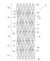
図1は、本発明の一実施例の生体内留置用ステントの正面図である。図2は、図1の生体内留置用ステントの展開図である。図3は、図2のA−A線拡大断面図である。図4は、本発明の他の実施例の生体内留置用ステントの線状部の拡大断面図である。図5は、本発明の他の実施例の生体内留置用ステントの線状部の拡大断面図である。図6は、本発明の他の実施例の生体内留置用ステントの線状部の拡大断面図である。図7は、本発明の他の実施例の生体内留置用ステントの線状部の拡大断面図である。図8は、図2の部分拡大図である。図9は、図1に示すステントの製造時の展開図である。The in-vivo indwelling stent of the present invention will be described using the following preferred embodiments.
FIG. 1 is a front view of an in-vivo stent according to an embodiment of the present invention. FIG. 2 is a development view of the in-vivo stent of FIG. FIG. 3 is an enlarged cross-sectional view taken along line AA in FIG. FIG. 4 is an enlarged cross-sectional view of a linear portion of an indwelling stent according to another embodiment of the present invention. FIG. 5 is an enlarged cross-sectional view of a linear portion of an indwelling stent according to another embodiment of the present invention. FIG. 6 is an enlarged cross-sectional view of a linear portion of an in-vivo stent according to another embodiment of the present invention. FIG. 7 is an enlarged cross-sectional view of a linear portion of an indwelling stent according to another embodiment of the present invention. FIG. 8 is a partially enlarged view of FIG. FIG. 9 is a development view of the stent shown in FIG. 1 at the time of manufacturing.
本発明の生体内留置用ステント1は、金属材料により形成された外面側ステント基体11と、金属材料により形成され、かつ、外面側ステント基体11内に位置する内面側ステント基体12と、外面側ステント基体11と内面側ステント基体12間に位置し、外面側ステント基体11と内面側ステント基体12とを接着する生分解性ポリマー含有樹脂性接着層13とを備える。そして、生分解性ポリマー含有樹脂製接着層13は、生理活性物質を放出可能に含有している。
そして、この実施例の生体内留置用ステント1では、外面側ステント基体11は、線状体により構成された所定のステント形態を備え、内面側ステント基体12は、外面側ステント基体11のステント形態に対応した形態を備え、かつ、外面側ステント基体11内にステント形態が重なるように配置されている。
つまり、本発明のステント1は、外表面および内表面が金属層であり、その両者間が生分解性ポリマー含有接着性樹脂層である多層構造を持つものとなっている。The in-vivo indwelling stent 1 of the present invention includes an outer surface-
In the in-vivo indwelling stent 1 of this embodiment, the outer surface
That is, the stent 1 of the present invention has a multilayer structure in which an outer surface and an inner surface are metal layers, and a biodegradable polymer-containing adhesive resin layer is interposed between the two.
そして、樹脂製接着層13は、実質的に前記生分解性ポリマーにより形成されており、前記樹脂製接着層は、前記生分解性ポリマーの分解後において、実質的に消失するものであることが好ましい。このようなものであれば、生体内への留置後、樹脂製接着層13の消失により、その消失分肉厚が薄くなり、再狭窄の要因となる可能性が少ないものとなる。
なお、樹脂製接着層13は、含有する生分解性ポリマーの分解後においても、外面側ステント基体11と内面側ステント基体12との接着状態を維持するものであってもよい。この場合には、生分解性ポリマー含有接着性樹脂層は、接着性を有しかつ所定量の非生分解性成分を含有するものとなる。この場合においても、樹脂製接着層13中の生分解性ポリマーの消失により、その消失分肉厚が薄くなり、再狭窄の要因となる可能性を少なくする。The
The
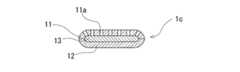
また、外面側ステント基体11は、図4に示すステント1aのように、表面より樹脂性接着層13まで延びる多数の細孔11aを備えているものであってもよい。このようにすることにより、樹脂製接着層13に含有されている生理活性物質の放出がより良好なものとなる。
また、図5に示すステント1bのように、外面側ステント基体11と内面側ステント基体12の周縁部は、近接する方向に湾曲するものであってもよい。このようにすることにより、ステント全体の保形性が高いものとなる。なお、外面側ステント基体11と内面側ステント基体12の周縁部は、図5に示すように、隙間16が形成されるようにし、完全に密着しないものとすることが好ましい。
さらに、図6に示すステント1cのように、外面側ステント基体11は、表面より樹脂性接着層13まで延びる多数の細孔11aを備え、さらに、外面側ステント基体11と内面側ステント基体12の周縁部は、近接する方向に湾曲するものであってもよい。このようにすることにより、ステント全体の保形性が高いものとなる。そして、外面側ステント基体11と内面側ステント基体12の周縁部は、図6に示すように、完全に密着するものであってもよい。この場合、樹脂製接着層13に含有されている生理活性物質は、細孔11aのみより流出するものとなり、良好な徐放が可能となる。Moreover, the outer surface side stent base |
Moreover, like the
Furthermore, like the
そして、上述した3層構造の実施例のステント1において、外面側ステント基体11の厚さとしては、0.03〜0.25mm程度が好適であり、好ましくは、0.05〜0.10mmである。内面側ステント基体12の厚さとしては、0.03〜0.25mm程度が好適であり、好ましくは、0.05〜0.10mmである。樹脂製接着層13の厚さとしては、0.001〜0.050mm程度が好適であり、好ましくは、0.005〜0.030mmである。 And in the stent 1 of the Example of the 3 layer structure mentioned above, as thickness of the outer surface side stent base |
さらに、本発明のステントとしては、図7に示すステント1dのように、金属材料により形成された外面側ステント基体11と、金属材料により形成され、かつ、外面側ステント基体内に位置する内面側ステント基体12と、金属材料により形成され、かつ、外面側ステント基体11と内面側ステント基体12間に位置する内部側ステント基体14と、外面側ステント基体11と内部側ステント基体間14に位置し、外面側ステント基体11と内部側ステント基体14とを接着する生分解性ポリマーを含有する第1の樹脂性接着層13と、内部側ステント基体14と内面側ステント基体12間に位置し、内部側ステント基体14と内面側ステント基体12とを接着する生分解性ポリマーを含有する第2の樹脂性接着層15とを備え、第1の樹脂製接着層13は、生理活性物質を放出可能に含有しているものであってもよい。 Furthermore, as a stent of the present invention, as in the
そして、第1樹脂製接着層13および第2の樹脂製接着層15は、実質的に生分解性ポリマーにより形成されており、第1樹脂製接着層13および第2の樹脂製接着層15は、生分解性ポリマーの分解後において、実質的に消失するものであることが好ましい。
また、第1樹脂製接着層13および第2の樹脂製接着層15は、含有する生分解性ポリマーの分解後においても、外面側ステント基体11と内部側ステント基体14との接着状態および内面側ステント基体12と内部側ステント基体14との接着状態を維持するものであってもよい。この場合には、第1樹脂製接着層13および第2の樹脂製接着層15は、接着性を有しかつ所定量の非生分解性成分を含有するものとなる。The first
In addition, the first
この実施例のステント1dにおいて、外表面および内表面が金属層であり、その両者間が接着性樹脂層である多層構造を持つものとなっている。具体的には、3つの金属層と、それぞれの間に配置された2つの樹脂製接着層からなる5層構造となっている。なお、本発明のステントとしては、このような5層構造に限定されるものではなく、さらに多層構造となっているものであってもよい。具体的には、内部側ステント基体が、外面側および内面側が金属により形成された金属表面層となっているとともに、内部が、樹脂製接着層と金属層とが交互に積層した多層構造となっているものであってもよい。
この実施例のステント1dにおいて、外面側ステント基体11は、線状体により構成された所定のステント形態を備え、内部側ステント基体14は、外面側ステント基体11のステント形態に対応した形態を備え、かつ、外面側ステント基体11内にステント形態が重なるように配置され、内面側ステント基体12は、内部側ステント基体14のステント形態に対応した形態を備え、かつ、内部側ステント基体14内にステント形態が重なるように配置されている。The
In the
そして、このような多層構造のものにおいても、図7に示すステント1dのように、外面側ステント基体11は、表面より第1の樹脂性接着層13まで延びる多数の細孔11aを備えているものであってもよい。このようにすることにより、樹脂製接着層13に含有されている生理活性物質の放出がより良好なものとなる。
また、第2の樹脂製接着層15は、第1の樹脂製接着層13に含有された生理活性物質と異なる生理活性物質を放出可能に含有していることが好ましい。さらに、内面側ステント基体12は、図7に示すステント1dのように、表面より第2の樹脂性接着層15まで延びる多数の細孔12aを備えるものであってもよい。このようにすることにより、第2の樹脂製接着層15に含有されている生理活性物質の放出がより良好なものとなる。Even in such a multilayer structure, like the
The second
そして、第1の樹脂製接着層13および第2の樹脂製接着層15は、生理活性物質を徐々に放出するために配合された生分解性材料を含有するとともに、生分解性材料の分解後においても外面側ステント基体12と内部側ステント基体14と内面側ステント基体12との接着状態を維持するものであることが好ましい。
そして、上述した5層構造の実施例のステント1dにおいて、外面側ステント基体11の厚さとしては、0.03〜0.15mm程度が好適であり、好ましくは、0.05〜0.10mmである。内面側ステント基体12の厚さとしては、0.03〜0.15mm程度が好適であり、好ましくは、0.05〜0.10mmである。内部側ステント基体14の厚さとしては、0.03〜0.15mm程度が好適であり、好ましくは、0.05〜0.10mmである。第1の樹脂製接着層13の厚さとしては、0.001〜0.050mm程度が好適であり、好ましくは、0.005〜0.030mmである。第2の樹脂製接着層15の厚さとしては、0.001〜0.050mm程度が好適であり、好ましくは、0.005〜0.030mmである。The first
In the above-described
そして、本発明のステントとしては、略管状体に形成され、生体内管腔への挿入のための直径を有し、該管状体の内部より半径方向に広がる力が付加されたときに拡張可能なステント、いわゆるバルーン拡張型ステントであることが好ましい。
この場合におけるステント基体11,12,14を形成する金属材料としては、ある程度の生体適合性を有するものが好ましく、例えば、ステンレス鋼、タンタルもしくはタンタル合金、プラチナもしくはプラチナ合金、金もしくは金合金、コバルトベース合金、コバルトクロム合金、チタン合金、ニオブ合金等が考えられる。またステント形状を作製した後に貴金属メッキ(金、プラチナ)をしてもよい。ステンレス鋼としては、最も耐腐食性のあるSUS316Lが好適である。
また、ステントの非拡張時の直径は、0.8〜1.8mm程度が好適であり、特に、0.9〜1.6mmがより好ましい。また、ステントの非拡張時の長さは、8〜40mm程度が好適である。また、一つの波線状環状体2の長さは、1.0〜2.5mm程度が好適である。The stent of the present invention is formed into a substantially tubular body, has a diameter for insertion into a lumen in a living body, and is expandable when a force that extends radially from the inside of the tubular body is applied. Preferably, it is a so-called balloon expandable stent.
In this case, the metal material forming the stent bases 11, 12, and 14 is preferably a material having a certain degree of biocompatibility. For example, stainless steel, tantalum or tantalum alloy, platinum or platinum alloy, gold or gold alloy, cobalt A base alloy, a cobalt chromium alloy, a titanium alloy, a niobium alloy, and the like are conceivable. Moreover, after producing the stent shape, precious metal plating (gold, platinum) may be performed. As stainless steel, SUS316L having the most corrosion resistance is suitable.
The diameter of the stent when not expanded is preferably about 0.8 to 1.8 mm, more preferably 0.9 to 1.6 mm. The length of the stent when not expanded is preferably about 8 to 40 mm. Further, the length of one wavy
樹脂製接着層13,15の形成材料としては、ゴム、エラストマー、可撓性樹脂が好ましい。ゴムとしては、例えば、シリコーンゴム、ラテックスゴムなどが好ましい。エラストマーとしては、フッ素系樹脂エラストマー、ポリウレタンエラストマー、ポリエステルエラストマー、ポリアミドエラストマー、ポリオレフィンエラストマー(例えば、ポリエチレンエラストマー、ポリプロピレンエラストマー)などが好ましい。可撓性樹脂としては、ポリウレタン、ポリエステル、ポリアミド、ポリ塩化ビニル、エチレン−酢酸ビニル共重合体、ポリオレフィン(例えば、ポリエチレン、ポリプロピレン、エチレン−プロピレン共重合体)などが好ましい。特に、エラストマー、ゴムが好適である。ゴムとしては、シリコーンゴムが好適である。さらに、シリコーンゴムとしては、低温硬化型もしくは常温硬化型シリコーンゴムが好ましい。 As a material for forming the resin
そして、上述したように、樹脂製接着層は、生理活性物質を徐々に放出するために配合された生分解性材料を含有する。なお、生分解性材料は、生分解性材料の分解後においても、樹脂製接着層は、ステント基体間の接着状態(ステント構造)を維持可能な程度含有される。樹脂製接着層形成材料中に含有される生分解性材料は、使用する接着層形成材および生分解性材料によっても相違するが、30〜50重量%程度が好ましい。
生分解性材料としては、生体内で酵素的、非酵素的に分解され、分解物が毒性を示さないものであれば特に限定されないが、例えば、ポリ乳酸、ポリグリコール酸、ポリ乳酸−ポリグリコール酸共重合体、ポリカプロラクトン、ポリ乳酸−ポリカプロラクトン共重合体、ポリオルソエステル、ポリホスファゼン、ポリリン酸エステル、ポリヒドロキシ酪酸、ポリリンゴ酸、ポリα−アミノ酸、コラーゲン、ゼラチン、ラミニン、ヘパラン硫酸、フィブロネクチン、ビトロネクチン、コンドロイチン硫酸、ヒアルロン酸、ポリペプチド、キチン、キトサンなどが使用できる。And as above-mentioned, the resin-made adhesive layer contains the biodegradable material mix | blended in order to discharge | release a bioactive substance gradually. It should be noted that the biodegradable material is contained in such a degree that the adhesive layer made of resin can maintain the adhesion state (stent structure) between the stent substrates even after the biodegradable material is decomposed. The biodegradable material contained in the resin adhesive layer forming material varies depending on the adhesive layer forming material and the biodegradable material used, but is preferably about 30 to 50% by weight.
The biodegradable material is not particularly limited as long as it is enzymatically or non-enzymatically degraded in the living body and the degradation product does not show toxicity. For example, polylactic acid, polyglycolic acid, polylactic acid-polyglycol Acid copolymer, polycaprolactone, polylactic acid-polycaprolactone copolymer, polyorthoester, polyphosphazene, polyphosphate ester, polyhydroxybutyric acid, polymalic acid, poly α-amino acid, collagen, gelatin, laminin, heparan sulfate, fibronectin Vitronectin, chondroitin sulfate, hyaluronic acid, polypeptide, chitin, chitosan and the like can be used.
生理活性物質としては、内膜肥厚を抑制する薬剤、抗癌剤、免疫抑制剤、抗生物質、抗リウマチ剤、抗血栓薬、HMG−CoA還元酵素阻害剤、ACE阻害剤、カルシウム拮抗剤、抗高脂血症剤、抗炎症剤、インテグリン阻害薬、抗アレルギー剤、抗酸化剤、GPIIbIIIa拮抗薬、レチノイド、フラボノイドおよびカロチノイド、脂質改善薬、DNA合成阻害剤、チロシンキナーゼ阻害剤、抗血小板薬、血管平滑筋増殖抑制薬、抗炎症薬、生体由来材料、インターフェロンおよび遺伝子工学により生成される上皮細胞などが使用される。そして、上記の薬剤等の2種以上の混合物を使用してもよい。 Physiologically active substances include agents that suppress intimal thickening, anticancer agents, immunosuppressive agents, antibiotics, anti-rheumatic agents, antithrombotic agents, HMG-CoA reductase inhibitors, ACE inhibitors, calcium antagonists, anti-high fats Antihypertensive agent, anti-inflammatory agent, integrin inhibitor, antiallergic agent, antioxidant, GPIIbIIIa antagonist, retinoid, flavonoid and carotenoid, lipid improver, DNA synthesis inhibitor, tyrosine kinase inhibitor, antiplatelet agent, vascular smoothing Muscle growth inhibitors, anti-inflammatory drugs, biological materials, interferons and epithelial cells generated by genetic engineering are used. And you may use 2 or more types of mixtures, such as said chemical | medical agent.
抗癌剤としては、例えば、ビンクリスチン、ビンブラスチン、ビンデシン、イリノテカン、ピラルビシン、パクリタキセル、ドセタキセル、メトトレキサート等が好ましい。免疫抑制剤としては、例えば、シロリムス、タクロリムス、アザチオプリン、シクロスポリン、シクロホスファミド、ミコフェノール酸モフェチル、グスペリムス、ミゾリビン等が好ましい。抗生物質としては、例えば、マイトマイシン、アドリアマイシン、ドキソルビシン、アクチノマイシン、ダウノルビシン、イダルビシン、ピラルビシン、アクラルビシン、エピルビシン、ペプロマイシン、ジノスタチンスチマラマー等が好ましい。抗リウマチ剤としては、例えば、メトトレキサート、チオリンゴ酸ナトリウム、ペニシラミン、ロベンザリット等が好ましい。抗血栓薬としては、例えば、ヘパリン、アスピリン、抗トロンビン製剤、チクロピジン、ヒルジン等が好ましい。HMG−CoA還元酵素阻害剤としては、例えば、セリバスタチン、セリバスタチンナトリウム、アトルバスタチン、ニスバスタチン、イタバスタチン、フルバスタチン、フルバスタチンナトリウム、シンバスタチン、ロバスタチン、プラバスタチン等が好ましい。ACE阻害剤としては、例えば、キナプリル、ペリンドプリルエルブミン、トランドラプリル、シラザプリル、テモカプリル、デラプリル、マレイン酸エナラプリル、リシノプリル、カプトプリル等が好ましい。カルシウム拮抗剤としては、例えば、ニフェジピン、ニルバジピン、ジルチアゼム、ベニジピン、ニソルジピン等が好ましい。抗高脂血症剤としては、例えば、プロブコールが好ましい。抗アレルギー剤としては、例えば、トラニラストが好ましい。レチノイドとしては、例えば、オールトランスレチノイン酸フラボノイドおよびカロチノイドとしては、例えば、カテキン類、特にエピガロカテキンガレート、アントシアニン、プロアントシアニジン、リコピン、β−カロチン等が好ましい。チロシンキナーゼ阻害剤としては、例えば、ゲニステイン、チルフォスチン、アーブスタチン等が好ましい。抗炎症剤としては、例えば、デキサメタゾン、プレドニゾロン等のステロイドが好ましい。生体由来材料としては、例えば、EGF(epidermal growth factor)、VEGF(vascular endothelial growth factor)、HGF(hepatocyte growth factor)、PDGF(platelet derived growth factor)、bFGF(basic fibroblast growth factor)等が好ましい。 As the anticancer agent, for example, vincristine, vinblastine, vindesine, irinotecan, pirarubicin, paclitaxel, docetaxel, methotrexate and the like are preferable. As the immunosuppressant, for example, sirolimus, tacrolimus, azathioprine, cyclosporine, cyclophosphamide, mycophenolate mofetil, gusperimus, mizoribine and the like are preferable. As the antibiotic, for example, mitomycin, adriamycin, doxorubicin, actinomycin, daunorubicin, idarubicin, pirarubicin, aclarubicin, epirubicin, pepromycin, dinostatin styramer and the like are preferable. As the anti-rheumatic agent, for example, methotrexate, sodium thiomalate, penicillamine, lobenzalit and the like are preferable. As the antithrombotic drug, for example, heparin, aspirin, antithrombin preparation, ticlopidine, hirudin and the like are preferable. As the HMG-CoA reductase inhibitor, for example, cerivastatin, cerivastatin sodium, atorvastatin, nisvastatin, itavastatin, fluvastatin, fluvastatin sodium, simvastatin, lovastatin, pravastatin and the like are preferable. As the ACE inhibitor, for example, quinapril, perindopril erbumine, trandolapril, cilazapril, temocapril, delapril, enalapril maleate, lisinopril, captopril and the like are preferable. As the calcium antagonist, for example, nifedipine, nilvadipine, diltiazem, benidipine, nisoldipine and the like are preferable. As the antihyperlipidemic agent, for example, probucol is preferable. As the antiallergic agent, for example, tranilast is preferable. As the retinoid, for example, as the all-trans retinoic acid flavonoid and carotenoid, for example, catechins, particularly epigallocatechin gallate, anthocyanin, proanthocyanidins, lycopene, β-carotene and the like are preferable. As the tyrosine kinase inhibitor, for example, genistein, tyrphostin, arbustatin and the like are preferable. As the anti-inflammatory agent, for example, steroids such as dexamethasone and prednisolone are preferable. As the biological material, for example, EGF (epidermal growth factor), VEGF (vascular endothelial growth factor), HGF (hepatocyte growth factor), PDGF (platelet derived growth factor), bFGF (basic fibroblast growth factor) and the like are preferable.
そして、上述した実施例のステント1dのように、外表面側となる第1の接着性樹脂層に含有される生理活性物質としては、抗癌剤、免疫抑制剤、レチノイド、フラボノイド、DNA合成阻害剤、チロシンキナーゼ阻害剤からなる群より選択される少なくとも1種などが好適である。
また、内面側となる第2の接着性樹脂層に含有される生理活性物質としては、抗生物質、抗リウマチ剤、抗血栓薬、HMG−CoA還元酵素阻害剤、ACE阻害剤、カルシウム拮抗剤、抗高脂血症薬、インテグリン阻害薬、抗アレルギー剤、抗酸化剤、GPIIbIIIa拮抗薬、カロチノイド、脂質改善薬、抗血小板薬、抗炎症薬、生体由来材料、インターフェロン、およびNO産生促進物質からなる群より選択される少なくとも1種などが好適である。And like the
In addition, as the physiologically active substance contained in the second adhesive resin layer on the inner surface side, antibiotics, anti-rheumatic agents, antithrombotic agents, HMG-CoA reductase inhibitors, ACE inhibitors, calcium antagonists, Antihyperlipidemic drugs, integrin inhibitors, antiallergic agents, antioxidants, GPIIbIIIa antagonists, carotenoids, lipid improvers, antiplatelet drugs, anti-inflammatory drugs, biological materials, interferons, and NO production promoters At least one selected from the group is preferred.
また、本発明の金属製のステント基体は、接着性樹脂層との接着性を高めるために、接着性樹脂層と向かい合う面の全体もしくは一部が前処理されても良い。前処理としては、親和性の高い材料をプライマーとして表面に被覆する方法が好ましい。プライマー材料としては、種々のものが使用可能であるが、最も好ましいものは加水分解性基と有機官能基とを有するシランカップリング剤である。シランカップリング剤の加水分解性基(たとえばアルコキシ基)の分解により生成したシラノール基は金属製のステント 本体と共有結合等により結合され、シランカップリング剤の有機官能基(例えばエポキシ基、アミノ基、メルカプト基、ビニル基、メタクリロキシ基)は、樹脂製接着層中のポリマーと化学結合により結合することができる。具体的なシランカップリング剤としては、例えばγ−アミノプロピルエトキシシラン、γ−グリシドキシプロピルメチルジメトキシシラン等が挙げられる。シランカップリング剤以外のプライマー材料としては、例えば有機チタン系カップリング剤、アルミニウム系カップリング剤、クロム系カップリング剤、有機リン酸系カップリング剤、ポリパラキシレン等の有機蒸着膜、シアノアクリレート系接着剤、ポリウレタン系のペーストレジン等が挙げられる。 In addition, the metal stent substrate of the present invention may be pretreated on the whole or a part of the surface facing the adhesive resin layer in order to improve the adhesiveness with the adhesive resin layer. As the pretreatment, a method of coating the surface with a material having high affinity as a primer is preferable. Although various materials can be used as the primer material, the most preferable one is a silane coupling agent having a hydrolyzable group and an organic functional group. Silanol groups generated by the decomposition of hydrolyzable groups (for example, alkoxy groups) of the silane coupling agent are bonded to the metal stent body by covalent bonds or the like, and organic functional groups (for example, epoxy groups, amino groups) of the silane coupling agent. , A mercapto group, a vinyl group, and a methacryloxy group) can be bonded to the polymer in the resin adhesive layer by a chemical bond. Specific examples of the silane coupling agent include γ-aminopropylethoxysilane and γ-glycidoxypropylmethyldimethoxysilane. Examples of primer materials other than silane coupling agents include organic titanium coupling agents, aluminum coupling agents, chromium coupling agents, organic phosphoric acid coupling agents, organic vapor deposition films such as polyparaxylene, and cyanoacrylates. Adhesives, polyurethane-based paste resins, and the like.
また、ステントとしては、挿入時に縮径可能であり、かつ、体内放出時に拡径(復元)するいわゆるセルフ拡張型ステントであってもよい。
この場合、金属製ステント基体の構成材料としては、超弾性金属が好適である。超弾性金属としては、超弾性合金が好適に使用される。ここでいう超弾性合金とは一般に形状記憶合金といわれ、少なくとも生体温度(37℃付近)で超弾性を示すものである。特に好ましくは、49〜53原子%NiのTi−Ni合金、38.5〜41.5重量%ZnのCu−Zn合金、1〜10重量%XのCu−Zn−X合金(X=Be,Si,Sn,Al,Ga)、36〜38原子%AlのNi−Al合金等の超弾性金属体が好適に使用される。特に好ましくは、上記のTi−Ni合金である。また、Ti−Ni合金の一部を0.01〜10.0%Xで置換したTi−Ni−X合金(X=Co,Fe,Mn,Cr,V,Al,Nb,W,Bなど)とすること、またはTi−Ni合金の一部を0.01〜30.0%原子で置換したTi−Ni−X合金(X=Cu,Pb,Zr)とすること、また、冷間加工率または/および最終熱処理の条件を選択することにより、機械的特性を適宜変えることができる。また、上記のTi−Ni−X合金を用いて冷間加工率および/または最終熱処理の条件を選択することにより、機械的特性を適宜変えることができる。使用される超弾性合金の座屈強度(負荷時の降伏応力)は、5〜200kg/mm2(22℃)、より好ましくは、8〜150kg/mm2、復元応力(除荷時の降伏応力)は、3〜180kg/mm2(22℃)、より好ましくは、5〜130kg/mm2である。ここでいう超弾性とは、使用温度において通常の金属が塑性変形する領域まで変形(曲げ、引張り、圧縮)させても、変形の解放後、加熱を必要とせずにほぼ圧縮前の形状に回復することを意味する。The stent may be a so-called self-expandable stent that can be reduced in diameter when inserted and expands (restores) when released into the body.
In this case, a super elastic metal is suitable as a constituent material of the metal stent substrate. As the superelastic metal, a superelastic alloy is preferably used. The superelastic alloy here is generally called a shape memory alloy, and exhibits superelasticity at least at a living body temperature (around 37 ° C.). Particularly preferably, a Ti—Ni alloy of 49 to 53 atomic% Ni, a Cu—Zn alloy of 38.5 to 41.5 wt% Zn, and a Cu—Zn—X alloy of 1 to 10 wt% X (X = Be, A super elastic metal body such as Si, Sn, Al, Ga), Ni-Al alloy of 36-38 atomic% Al is preferably used. Particularly preferred is the Ti—Ni alloy described above. Further, a Ti—Ni—X alloy in which a part of the Ti—Ni alloy is substituted with 0.01 to 10.0% X (X = Co, Fe, Mn, Cr, V, Al, Nb, W, B, etc.) Or a Ti—Ni—X alloy (X = Cu, Pb, Zr) in which a part of the Ti—Ni alloy is substituted by 0.01 to 30.0% atoms, and the cold work rate Alternatively, mechanical characteristics can be appropriately changed by selecting conditions for final heat treatment. Further, the mechanical characteristics can be appropriately changed by selecting the cold work rate and / or the final heat treatment conditions using the Ti—Ni—X alloy. The buckling strength (yield stress during loading) of the superelastic alloy used is 5 to 200 kg / mm2 (22 ° C.), more preferably 8 to 150 kg / mm2. Restoring stress (yield stress during unloading) ) Is 3 to 180 kg / mm2 (22 ° C.), more preferably 5 to 130 kg / mm2 . Superelasticity here means that even if it is deformed (bending, pulling, compressing) to a region where normal metal is plastically deformed at the operating temperature, it will recover to its almost uncompressed shape without the need for heating after the deformation is released. It means to do.
そして、本発明のステントは、例えば、以下のようにして製造することができる。
最初に所定の内径を有する金属管状体(具体的には、金属パイプ)とこの金属管状体の内径より若干小さい外径を有する金属管状体(具体的には、金属パイプ)を準備し、それら金属パイプよりステント構造体(線状体により形成されるフレーム形態)が同じでありかつ径のみが異なる2つのステント基体を作製する。これは、金属パイプより、ステント構造体となる部分以外を除去することにより作製できる。具体的には、金属パイプを、例えば、フォトファブリケーションと呼ばれるマスキングと化学薬品を使用したエッチング方法、型による放電加工法、切削加工(例えば、機械研磨、レーザー切削加工)などにより不要部分を除去することにより行われる。また、ステント構造体を作製した後に、化学研磨あるいは電解研磨を用いて、構造体のエッジを研磨することが好ましい。And the stent of this invention can be manufactured as follows, for example.
First, a metal tubular body (specifically, a metal pipe) having a predetermined inner diameter and a metal tubular body (specifically, a metal pipe) having an outer diameter slightly smaller than the inner diameter of the metal tubular body are prepared. Two stent bases having the same stent structure (frame form formed of linear bodies) and different diameters are produced from metal pipes. This can be produced by removing the portion other than the portion that becomes the stent structure from the metal pipe. Specifically, unnecessary portions of metal pipes are removed by, for example, photofabrication masking and chemical etching methods, electrical discharge machining using molds, and cutting (for example, mechanical polishing and laser cutting). Is done. In addition, it is preferable to polish the edge of the structure using chemical polishing or electrolytic polishing after the stent structure is manufactured.
そして、上記のようにして作製された小径側のステント基体の表面に、生理活性物質を含有した(好ましくは、生分解性材料も含有する)接着性樹脂層形成材料を塗布し、接着性樹脂層形成材料の硬化前に、大径側のステント基体を被嵌し、圧着させることにより、製造することができる。そして、大径側のステント基体の形成素材としては、多孔性金属パイプを用いることにより、形成されるステントの外面側ステント基体を多孔性のものとすることができる。 Then, an adhesive resin layer-forming material containing a physiologically active substance (preferably containing a biodegradable material) is applied to the surface of the small-diameter stent base produced as described above, and the adhesive resin is applied. Before the layer-forming material is cured, the large-diameter side stent substrate is fitted and pressed so as to be manufactured. And as a formation raw material of the large diameter side stent base | substrate, the outer surface side stent base | substrate of the formed stent can be made porous by using a porous metal pipe.
また、ステントの製造方法は、上記のものに限定されるものではなく、例えば、最初に所定の内径を有する金属管状体(具体的には、金属パイプ)とこの金属管状体の内径より若干小さい外径を有する金属管状体(具体的には、金属パイプ)を準備し、小径側の金属パイプの表面に、接着性樹脂層形成材料(好ましくは、生分解性材料を含有)を塗布し、接着性樹脂層形成材料の硬化前に、大径側の金属パイプを被嵌し、圧着させることにより、内外面が金属により構成された多層パイプを作製する。そして、多層パイプより、ステント構造体となる部分以外を除去する。ステント構造体となる部分以外を除去は、上述の方法により行うことができる。このようにして、作製されたステント構造物を生理活性物質を溶解した溶液中に浸漬し、生理活性物質を接着性樹脂層形成材料中に担持(具体的には、移行、吸着)させることにより、本発明のステントを製造することができる。なお、生理活性物質を溶解した溶液としては、接着性樹脂層形成材料を膨潤もしくは若干溶解するものが用いられる。なお、この場合には、大径側のステント基体の形成素材としては、多孔性金属パイプを用いることが好ましく、このようにすることにより、接着性樹脂層形成材料中への生理活性物質の担持量を多くすることができる。なお、上述したすべての製造方法において、金属製ステント構造体もしくは金属パイプは、接着性樹脂層との接着性を高めるために、上述したようなプライマー被覆を処理を行ってもよい。 In addition, the stent manufacturing method is not limited to the above-described one. For example, a metal tubular body (specifically, a metal pipe) having a predetermined inner diameter at first and a slightly smaller inner diameter than the metal tubular body. A metal tubular body having an outer diameter (specifically, a metal pipe) is prepared, and an adhesive resin layer forming material (preferably containing a biodegradable material) is applied to the surface of the metal pipe on the small diameter side, Before the adhesive resin layer forming material is cured, a large-diameter metal pipe is fitted and crimped to produce a multi-layer pipe whose inner and outer surfaces are made of metal. Then, the portion other than the portion that becomes the stent structure is removed from the multilayer pipe. Removal of portions other than the portion that becomes the stent structure can be performed by the method described above. By immersing the prepared stent structure in a solution in which a physiologically active substance is dissolved, and carrying (specifically, migration, adsorption) the physiologically active substance in the adhesive resin layer forming material The stent of the present invention can be manufactured. As the solution in which the physiologically active substance is dissolved, a solution that swells or slightly dissolves the adhesive resin layer forming material is used. In this case, it is preferable to use a porous metal pipe as a material for forming the large-diameter stent base. By doing so, the physiologically active substance is supported in the adhesive resin layer forming material. The amount can be increased. In all the manufacturing methods described above, the metal stent structure or the metal pipe may be subjected to the primer coating as described above in order to improve the adhesiveness with the adhesive resin layer.
また、本発明のステントにおけるステントの形態(線状体により構成されるフレーム形態)としては、どのようなものであってもよい。
図1に示す実施例の生体内留置用ステント1では、波線状環状体2がステントの軸方向に隣り合うように複数配列され、隣り合う波線状環状体2が接続された形態を有する略管状体に形成され、生体内管腔への挿入のための直径を有し、管状体の内部より半径方向に広がる力が付加されたときに拡張可能なものとなっている。そして、波線状環状体2は、ステント1の拡張前および拡張後において、ステント1の中心軸と平行に伸びる平行直線状部21を備え、ステント1は、隣り合う波線状環状体2の平行直線状部21の端部同士を接続する接続部3を備えている。
この実施例のステント1は、略管状体に形成され、生体内への挿入のための直径を有し、管状体の内部より半径方向外方に広がる力が付与されたときに伸長可能なものであり、いわゆるバルーン拡張型ステントである。In addition, any stent may be used in the stent of the present invention (a frame formed of a linear body).
In the indwelling stent 1 of the embodiment shown in FIG. 1, a plurality of wavy
The stent 1 of this embodiment is formed in a substantially tubular body, has a diameter for insertion into a living body, and is extensible when a force that extends radially outward from the inside of the tubular body is applied. It is a so-called balloon expandable stent.
本発明のステント1は、図1および図2に示すように、複数の波線状環状体2を軸方向に隣り合うように配列するとともに、それぞれを接続した形態となっている。
ステント1を形成する波線状環状体2の数としては、図1、図2、図8および図9に示すものでは、14となっている。波線状環状体2の数としては、ステントの長さによって相違し、4〜50が好ましく、特に、10〜35が好ましい。
そして、各波線状環状体2は、ステント1の軸方向の一端側に頂点を有する複数の一端側屈曲部25,27およびステント1の軸方向の他端側に頂点を有する複数の他端側屈曲部26,28を有するとともに、環状に連続した無端の波線状体により構成されている。環状体2における一端側屈曲部25,27と他端側屈曲部26,28は、交互に形成されており、かつそれぞれの数は同じとなっている。As shown in FIGS. 1 and 2, the stent 1 of the present invention has a configuration in which a plurality of wavy
The number of wavy-line
Each wavy-line
そして、波線状環状体2は、図1、図2、図8および図9に示すように、平行直線状部21の一端と屈曲部25(25a)を介して接続し、かつ、少なくともステント1の拡張時にステント1の中心軸に対して所定角度斜めとなる第1の傾斜直線状部22と、第1の傾斜直線状部22の一端と屈曲部26を介して接続し、かつ、ステントの中心軸に対して所定角度斜めに伸びる傾斜線状部(この実施例では、傾斜曲線状部)23と、傾斜曲線状部23の一端と屈曲部27を介して接続し、かつ、少なくともステント1の拡張時にステント1の中心軸に対して所定角度斜めとなる第2の傾斜直線状部24の4つの線状部からなる変形M字線状部20が複数連続したものとなっている。そして、隣り合う変形M字線状部20は、第2の傾斜直線状部24の一端と平行直線状部21の他端を接続する屈曲部28(28a)により接続されることにより、無端の波線状環状体2を構成している。このため、ステントの拡張時における波線状環状体2の軸方向長のショートニングを抑制するとともに、波線状環状体2に十分な拡張保持力を付与する。 As shown in FIGS. 1, 2, 8, and 9, the wavy
また、この実施例のステント1では、一端側屈曲部25,27の頂点および他端側屈曲部26,28の頂点が、ステントの軸方向に対してほぼ直線状に並んだものとなっている。
そして、隣り合う波線状環状体2は、接続部3により接続されている。特に、この実施例のステント1では、隣り合う波線状環状体2の平行直線状部21の端部同士は、近接しかつ短い接続部3により接続されている。このため、隣り合う波線状環状体2間の距離が短いものとなり、隣り合う波線状環状体2間に起因する低拡張力部分の形成が極めて少ないものとなる。Further, in the stent 1 of this embodiment, the apexes of the one end side bent
Adjacent wavy-line
また、この実施例のステント1では、図1、図2、図8および図9に示すように、接続部3で接続された2つの平行直線状部21は、ほぼ直線状となっている。このため、ステントの拡張時における隣り合う波線状環状体間におけるステントのショートニングを防止できる。そして、このステント1では、隣り合う波線状環状体2を接続する複数の接続部3を備えている。このため、隣り合う波線状環状体が不必要に離間することがなく、ステント全体として十分な拡張力を発揮する。
そして、この実施例では、軸方向に連続する2つを越える(言い換えれば、3以上)平行直線状部21が、接続部により連結され一体化した部分を持たないものとなっている。つまり、接続部3により2本のみの平行直線状部21が接続された状態となっており、3本の平行直線状部21が一体化した部分を持たないものとなっている。このため、一つの波線状環状体が血管の変形に追従するように変化した時の負荷が、隣り合わない波線状環状体にまで直接的(もしくは直線的)に伝達されることを抑制でき、波線状環状体個々の独立した拡張機能を発揮する。Moreover, in the stent 1 of this Example, as shown in FIG.1, FIG.2, FIG.8 and FIG. 9, the two parallel
In this embodiment, the parallel
また、ステント1は、隣り合う波線状環状体2を接続する複数の接続部3を備えている。このため、隣り合う波線状環状体が不必要に離間することがなく、ステント全体として十分な拡張力を発揮する。なお、接続部3は、隣り合う波線状環状体間に一つのみ設けてもよい。また、接続部3のステント1の軸方向長さとしては、1.0mm以下程度が好ましく、特に、0.1〜0.4mmが好ましい。
そして、このステント1では、隣り合う波線状環状体2を接続する2つの接続部3を備えており、2つの接続部は、向かい合う位置に設けられている。また、接続部3は、ステント1の軸方向に連続しないように配置されている。具体的には、この実施例のステント1では、図1、図2、図8および図9に示すように、2つの接続部3は向かい合う位置に設けられており、この接続部3と軸方向に隣り合う2つの接続部3は、向かい合うとともに、上記の接続部とステント1の中心軸に対して約90°ずれたものとなっている。In addition, the stent 1 includes a plurality of
And this stent 1 is provided with the two
ステント1は、図1および図2に示した状態より外径の大きい状態に形成した後、拡張可能なバルーンを有する器具のバルーン上に縮径させることにより装着される。そして、ステント1は、バルーンを拡張することにより、拡張する。
また、ステントの非拡張時の直径は、0.8〜1.8mm程度が好適であり、特に、0.9〜1.6mmがより好ましい。また、ステントの非拡張時の長さは、8〜40mm程度が好適である。また、一つの波線状環状体2の長さは、1.0〜2.5mm程度が好適である。The stent 1 is mounted by forming a stent having a larger outer diameter than the state shown in FIGS. 1 and 2 and then reducing the diameter onto a balloon of an instrument having an expandable balloon. The stent 1 is expanded by expanding the balloon.
The diameter of the stent when not expanded is preferably about 0.8 to 1.8 mm, more preferably 0.9 to 1.6 mm. The length of the stent when not expanded is preferably about 8 to 40 mm. Further, the length of one wavy
なお、本発明のステントの形態(線状体により構成されるフレーム形態)としては、上述したものに限定されるものではなく、どのようなものであってもよい。例えば、図10に示すように、波線状環状体ではなく、半径方向に広がる力が付加された時に伸張する多数の線状屈曲部と開口を有する複数のリング状線状体43を環状に配置したものであってもよい。
この実施例のステント40は、略管状体に形成され、生体内管腔への挿入のための直径を有し、管状体の内部より半径方向に広がる力が付加された時に拡張可能なステントである。ステント40は、半径方向に広がる力が付加された時に伸張する多数の線状屈曲部と開口を有する複数のリング状線状体43を環状となるように複数の接続部46により接続した環状ユニット44がステントの軸方向に複数配列され、かつ、隣り合う環状ユニット44を接続部にて連結するとともにステントの軸方向に連続しない連結部45を備え、さらに、連結部は、隣り合う環状ユニット間に複数かつ向かい合う位置もしくはステントの中心軸に対してほぼ等角度配置となるように設けられている。In addition, as a form (frame form comprised by a linear body) of the stent of this invention, it is not limited to what was mentioned above, What kind of thing may be sufficient. For example, as shown in FIG. 10, a plurality of ring-shaped
The
ステント40は、展開図である図10に示すように、ステント40の軸方向に長くかつ線状屈曲部41aと中央部開口を有するリング状線状体43が、ステントの中心軸に対してほぼ等角度配置にて略円周上に配列され、かつ、リング状線状体43の円周方向の隣接部(側部)間が接続部46にて接続された環状ユニット44からなり、かつ、複数の環状ユニット44がステント40の軸方向に並んでいる。さらに、一つの環状ユニット44の接続部46と隣り合う環状ユニット44の接続部46とが連結部45により少なくとも2カ所連結されている。ステント40は、見方を変えれば、多数の環状ユニット44が、連結部45により連結したことにより構成された管状体である。 As shown in FIG. 10, which is a developed view of the
環状ユニット44は、この実施例では、ほぼ等角度間隔に配置された6つのリング状線状体43を有する。一つのリング状線状体43は、ステント40の軸方向に長い略菱形状に形成され、かつ、中央がリング状線状体43の形状に対応して、略菱形に開口し、ステントの軸方向の両端部が線状屈曲部41aとなっている。このように、各リング状線状体43は、個々独立した閉鎖系をなす形状、言い換えれば、リング状線状体43は、ステント40の側面にて開口するリング状要素である。リング状線状体43がこのような形状を有するため、強い拡張保持力を発揮する。また、各リング状線状体43は、ステント40の中心軸より全体がほぼ等距離となるように、円周方向に湾曲している。 In this embodiment, the
リング状線状体43は、ステント40の軸方向の側部の中心と半径方向に隣り合う他のリング状線状体43の軸方向の側部の中心とが短い接続部46により接続されている。つまり、接続部46は、各リング状線状体43を円周方向にて接続している。接続部46は、ステント40が拡張されても実質的に変化しないので、拡張する時の力が各リング状線状体43の中心にかかりやすく、各リング状線状体43は均一に拡張(変形)可能である。
環状ユニット44の接続部46と隣り合う環状ユニット44の接続部46とは、比較的長く(接続部に比べて長く)、ステント40の軸方向に平行に形成された連結部45により連結されている。具体的には、環状ユニット44と隣り合う環状ユニット44とは、接続部46間を連結する連結部45により連結されている。また、ステント40の両端に位置するリング状線状体43の外側部分43bは、略半楕円状となっている。In the ring-shaped
The connecting
次に、本発明の血管拡張器具を図面に示す実施例を用いて説明する。
図11は、本発明の実施例の生体器官拡張器具の正面図である。図12は、図11に示した生体器官拡張器具の先端部の拡大部分断面図である。図13は、本発明の実施例の生体器官拡張器具の作用を説明するための説明図である。
本発明の血管拡張器具100は、チューブ状のシャフト本体部102と、シャフト本体部102の先端部に設けられた折り畳みおよび拡張可能なバルーン103と、折り畳まれた状態のバルーン103を被包するように装着され、かつバルーン103の拡張により拡張されるステント101とを備えるものである。Next, the vasodilator of the present invention will be described with reference to the embodiments shown in the drawings.
FIG. 11 is a front view of a living organ dilator according to an embodiment of the present invention. FIG. 12 is an enlarged partial cross-sectional view of the distal end portion of the living organ dilator shown in FIG. FIG. 13 is an explanatory diagram for explaining the operation of the living organ dilator according to the embodiment of the present invention.
The
ステント101としては、上述したステント1のようなものが使用される。なお、ここで使用されるステントは、生体内管腔への挿入のための直径を有し、管状体の内部より半径方向に広がる力が付加されたときに拡張可能ないわゆるバルーン拡張型ステントが用いられる。ステントとしては、バルーン103に装着された状態におけるステントの線状体部分が占める面積は、ステントの空隙部を含む外周面の面積の60%〜80%であることが好ましい。さらに、本発明の血管拡張器具100では、シャフト本体部102は、一端がバルーン103内と連通するバルーン拡張用ルーメンを備える。生体器官拡張器具100は、ステントの中央部となる位置のシャフト本体部の外面に固定されたX線造影性部材もしくはステントの中央部分の所定長の両端となる位置のシャフト本体部の外面に固定された2つのX線造影性部材を備えている。 As the
この実施例の生体器官拡張器具100では、図11に示すように、シャフト本体部102は、シャフト本体部102の先端にて一端が開口し、シャフト本体部102の後端部にて他端が開口するガイドワイヤールーメン115を備えている。
この生体器官拡張器具100は、シャフト本体部102と、シャフト本体部102の先端部に固定されたステント拡張用バルーン103と、このバルーン103上に装着されたステント101とを備える。シャフト本体部102は、内管112と外管113と分岐ハブ110とを備えている。In the living
The living
内管112は、図11に示すように、内部にガイドワイヤーを挿通するためのガイドワイヤールーメン115を備えるチューブ体である。内管112としては、長さは、100〜2500mm、より好ましくは、250〜2000mm、外径が、0.1〜1.0mm、より好ましくは、0.3〜0.7mm、肉厚10〜250μm、より好ましくは、20〜100μmのものである。そして、内管112は、外管113の内部に挿通され、その先端部が外管113より突出している。この内管112の外面と外管113の内面によりバルーン拡張用ルーメン116が形成されており、十分な容積を有している。外管113は、内部に内管112を挿通し、先端が内管112の先端よりやや後退した部分に位置するチューブ体である。
外管113としては、長さは、100〜2500mm、より好ましくは、250〜2000mm、外径が、0.5〜1.5mm、より好ましくは、0.7〜1.1mm、肉厚25〜200μm、より好ましくは、50〜100μmのものである。As shown in FIG. 11, the
The
この実施例の生体器官拡張器具100では、外管113は、先端側外管113aと本体側外管113bにより形成され、両者が接合されている。そして、先端側外管113aは、本体側外管113bとの接合部より先端側の部分において、テーパー状に縮径し、このテーパー部より先端側が細径となっている。
先端側外管113aの細径部での外径は、0.50〜1.5mm、好ましくは0.60〜1.1mmである。また、先端側外管113aの基端部および本体側外管113bの外径は、0.75〜1.5mm、好ましくは0.9〜1.1mmである。
そして、バルーン103は、先端側接合部103aおよび後端側接合部103bを有し、先端側接合部103aが内管112の先端より若干後端側の位置に固定され、後端側接合部103bが外管の先端に固定されている。また、バルーン103は、基端部付近にてバルーン拡張用ルーメン116と連通している。
内管112および外管113の形成材料としては、ある程度の可撓性を有するものが好ましく、例えば、ポリオレフィン(例えば、ポリエチレン、ポリプロピレン、エチレン−プロピレン共重合体、エチレン−酢酸ビニル共重合体など)、ポリ塩化ビニル、ポリアミドエラストマー、ポリウレタン等の熱可塑性樹脂、シリコーンゴム、ラテックスゴム等が使用でき、好ましくは上記の熱可塑性樹脂であり、より好ましくは、ポリオレフィンである。In the living
The outer diameter at the small diameter portion of the distal end side
The
As a material for forming the
バルーン103は、図12に示すように、折り畳み可能なものであり、拡張させない状態では、内管112の外周に折り畳まれた状態となることができるものである。バルーン103は、図13に示すように、装着されるステント101を拡張できるようにほぼ同一径の筒状部分(好ましくは、円筒部分)となった拡張可能部を有している。略円筒部分は、完全な円筒でなくてもよく、多角柱状のものであってもよい。そして、バルーン103は、上述のように、先端側接合部103aが内管112にまた後端側接合部103bが外管113の先端に接着剤または熱融着などにより液密に固着されている。また、このバルーン103では、拡張可能部と接合部との間がテーパー状に形成されている。
バルーン103は、バルーン103の内面と内管112の外面との間に拡張空間103cを形成する。この拡張空間103cは、後端部ではその全周において拡張用ルーメン116と連通している。このように、バルーン103の後端は、比較的大きい容積を有する拡張用ルーメンと連通しているので、拡張用ルーメン116よりバルーン内への拡張用流体の注入が確実である。As shown in FIG. 12, the
The
バルーン103の形成材料としては、ある程度の可撓性を有するものが好ましく、例えば、ポリオレフィン(例えば、ポリエチレン、ポリプロピレン、エチレン−プロピレン共重合体、エチレン−酢酸ビニル共重合体、架橋型エチレン−酢酸ビニル共重合体など)、ポリ塩化ビニル、ポリアミドエラストマー、ポリウレタン、ポリエステル(例えば、ポリエチレンテレフタレート)、ポリアリレーンサルファイド(例えば、ポリフェニレンサルファイド)等の熱可塑性樹脂、シリコーンゴム、ラテックスゴム等が使用できる。特に、延伸可能な材料であることが好ましく、バルーン103は、高い強度および拡張力を有する二軸延伸されたものが好ましい。
バルーン103の大きさとしては、拡張されたときの円筒部分(拡張可能部)の外径が、2〜4mm、好ましくは2.5〜3.5mmであり、長さが10〜50mm、好ましくは20〜40mmである。また、先端側接合部103aの外径が、0.9〜1.5mm、好ましくは1〜1.3mmであり、長さが1〜5mm、好ましくは1〜1.3mmである。また、後端側接合部103bの外径が、1〜1.6mm、好ましくは1.1〜1.5mmであり、長さが1〜5mm、好ましくは、2〜4mmである。As a material for forming the
As the size of the
そして、この血管拡張器具100は、図12に示すように、拡張されたときの円筒部分(拡張可能部)の両端となる位置のシャフト本体部の外面に固定された2つのX線造影性部材117、118を備えている。なお、ステント101の中央部分の所定長の両端となる位置のシャフト本体部102(この実施例では、内管112)の外面に固定された2つのX線造影性部材を備えるものとしてもよい。さらに、ステントの中央部となる位置のシャフト本体部の外面に固定された単独のX線造影性部材を設けるものとしてもよい。
X線造影性部材117、118は、所定の長さを有するリング状のもの、もしくは線状体をコイル状に巻き付けたものなどが好適であり、形成材料は、例えば、金、白金、タングステンあるいはそれらの合金、あるいは銀−パラジウム合金等が好適である。Then, as shown in FIG. 12, this
The
そして、バルーン103を被包するようにステント101が装着されている。ステントは、ステント拡張時より小径かつ折り畳まれたバルーンの外径より大きい内径の金属パイプを加工することにより作成される。そして、作成されたステント内にバルーンを挿入し、ステントの外面に対して均一な力を内側に向けて与え縮径させることにより製品状態のステントが形成される。つまり、上記のステント101は、バルーンへの圧縮装着時により完成する。 A
内管112と外管113との間(バルーン拡張用ルーメン116内)には、線状の剛性付与体(図示せず)が挿入されていてもよい。剛性付与体は、生体器官拡張器具100の可撓性をあまり低下させることなく、屈曲部位での生体器官拡張器具100の本体部102の極度の折れ曲がりを防止するとともに、生体器官拡張器具100の先端部の押し込みを容易にする。剛性付与体の先端部は、他の部分より研磨などの方法により細径となっていることが好ましい。また、剛性付与体は、細径部分の先端が、本体部外管113の先端部付近まで延びていることが好ましい。剛性付与体としては、金属線であることが好ましく、線径0.05〜1.50mm、好ましくは0.10〜1.00mmのステンレス鋼等の弾性金属、超弾性合金などであり、特に好ましくは、ばね用高張力ステンレス鋼、超弾性合金線である。 A linear rigidity imparting body (not shown) may be inserted between the
この実施例の生体器官拡張器具100では、図11に示すように、基端に分岐ハブ110が固定されている。分岐ハブ110は、ガイドワイヤールーメン115と連通しガイドワイヤーポートを形成するガイドワイヤー導入口109を有し、内管112に固着された内管ハブと、バルーン拡張用ルーメン116と連通しインジェクションポート111を有し、外管113に固着された外管ハブとからなっている。そして、外管ハブと内管ハブとは、固着されている。この分岐ハブ110の形成材料としては、ポリカーボネート、ポリアミド、ポリサルホン、ポリアリレート、メタクリレート−ブチレン−スチレン共重合体等の熱可塑性樹脂が好適に使用できる。
なお、生体器官拡張器具の構造は、上記のようなものに限定されるものではなく、生体器官拡張器具の中間部分にガイドワイヤールーメンと連通するガイドワイヤー挿入口を有するものであってもよい。In the living
Note that the structure of the living organ dilator is not limited to the above, and may have a guide wire insertion port communicating with the guide wire lumen at an intermediate portion of the living organ dilator.
1、40 生体内留置用ステント
11 外面側ステント基体
12 内面側ステント基体
13 樹脂製接着層DESCRIPTION OF
Claims (16)
Translated fromJapanesePriority Applications (2)
| Application Number | Priority Date | Filing Date | Title |
|---|---|---|---|
| JP2007254731AJP2009082353A (en) | 2007-09-28 | 2007-09-28 | In-vivo indwelling stent and living organ dilator |
| US12/239,272US20090088831A1 (en) | 2007-09-28 | 2008-09-26 | Stent and stent delivery device |
Applications Claiming Priority (1)
| Application Number | Priority Date | Filing Date | Title |
|---|---|---|---|
| JP2007254731AJP2009082353A (en) | 2007-09-28 | 2007-09-28 | In-vivo indwelling stent and living organ dilator |
Publications (1)
| Publication Number | Publication Date |
|---|---|
| JP2009082353Atrue JP2009082353A (en) | 2009-04-23 |
Family
ID=40509263
Family Applications (1)
| Application Number | Title | Priority Date | Filing Date |
|---|---|---|---|
| JP2007254731APendingJP2009082353A (en) | 2007-09-28 | 2007-09-28 | In-vivo indwelling stent and living organ dilator |
Country Status (2)
| Country | Link |
|---|---|
| US (1) | US20090088831A1 (en) |
| JP (1) | JP2009082353A (en) |
Cited By (2)
| Publication number | Priority date | Publication date | Assignee | Title |
|---|---|---|---|---|
| JP2012196252A (en)* | 2011-03-18 | 2012-10-18 | Terumo Corp | Drug eluting stent |
| JP2017520311A (en)* | 2014-06-28 | 2017-07-27 | コーディス・コーポレイション | Thin film composite recoverable in-pipe device and method of use |
Families Citing this family (26)
| Publication number | Priority date | Publication date | Assignee | Title |
|---|---|---|---|---|
| WO2003002243A2 (en) | 2001-06-27 | 2003-01-09 | Remon Medical Technologies Ltd. | Method and device for electrochemical formation of therapeutic species in vivo |
| US8840660B2 (en) | 2006-01-05 | 2014-09-23 | Boston Scientific Scimed, Inc. | Bioerodible endoprostheses and methods of making the same |
| US8089029B2 (en) | 2006-02-01 | 2012-01-03 | Boston Scientific Scimed, Inc. | Bioabsorbable metal medical device and method of manufacture |
| US8048150B2 (en) | 2006-04-12 | 2011-11-01 | Boston Scientific Scimed, Inc. | Endoprosthesis having a fiber meshwork disposed thereon |
| EP2054537A2 (en) | 2006-08-02 | 2009-05-06 | Boston Scientific Scimed, Inc. | Endoprosthesis with three-dimensional disintegration control |
| EP2959925B1 (en) | 2006-09-15 | 2018-08-29 | Boston Scientific Limited | Medical devices and methods of making the same |
| JP2010503489A (en) | 2006-09-15 | 2010-02-04 | ボストン サイエンティフィック リミテッド | Biodegradable endoprosthesis and method for producing the same |
| ES2357661T3 (en) | 2006-09-15 | 2011-04-28 | Boston Scientific Scimed, Inc. | BIOEROSIONABLE ENDOPROOTHESIS WITH BIOESTABLE INORGANIC LAYERS. |
| WO2008034066A1 (en) | 2006-09-15 | 2008-03-20 | Boston Scientific Limited | Bioerodible endoprostheses and methods of making the same |
| WO2008036548A2 (en) | 2006-09-18 | 2008-03-27 | Boston Scientific Limited | Endoprostheses |
| ES2506144T3 (en) | 2006-12-28 | 2014-10-13 | Boston Scientific Limited | Bioerodible endoprosthesis and their manufacturing procedure |
| US8052745B2 (en) | 2007-09-13 | 2011-11-08 | Boston Scientific Scimed, Inc. | Endoprosthesis |
| US7998192B2 (en) | 2008-05-09 | 2011-08-16 | Boston Scientific Scimed, Inc. | Endoprostheses |
| US8236046B2 (en) | 2008-06-10 | 2012-08-07 | Boston Scientific Scimed, Inc. | Bioerodible endoprosthesis |
| US7985252B2 (en) | 2008-07-30 | 2011-07-26 | Boston Scientific Scimed, Inc. | Bioerodible endoprosthesis |
| US8382824B2 (en) | 2008-10-03 | 2013-02-26 | Boston Scientific Scimed, Inc. | Medical implant having NANO-crystal grains with barrier layers of metal nitrides or fluorides |
| EP2403546A2 (en) | 2009-03-02 | 2012-01-11 | Boston Scientific Scimed, Inc. | Self-buffering medical implants |
| US8435281B2 (en) | 2009-04-10 | 2013-05-07 | Boston Scientific Scimed, Inc. | Bioerodible, implantable medical devices incorporating supersaturated magnesium alloys |
| US8668732B2 (en) | 2010-03-23 | 2014-03-11 | Boston Scientific Scimed, Inc. | Surface treated bioerodible metal endoprostheses |
| CN102309369B (en)* | 2010-07-09 | 2014-11-05 | 上海微创医疗器械(集团)有限公司 | Metal support and manufacturing method thereof |
| WO2012003803A1 (en)* | 2010-07-09 | 2012-01-12 | 微创医疗器械(上海)有限公司 | A drug carrying metal stent and manufacturing method therefor |
| CN102309368B (en)* | 2010-07-09 | 2014-11-05 | 上海微创医疗器械(集团)有限公司 | Body lumen drug-carrying bracket and preparation method thereof |
| US9566633B2 (en)* | 2012-11-15 | 2017-02-14 | Vactronix Scientific, Inc. | Stents having a hybrid pattern and methods of manufacture |
| CA2947896A1 (en) | 2014-05-23 | 2015-11-26 | Boston Scientific Scimed, Inc. | Deployment system incorporating application of adhesive |
| US9381103B2 (en)* | 2014-10-06 | 2016-07-05 | Abbott Cardiovascular Systems Inc. | Stent with elongating struts |
| CN112336496A (en)* | 2020-11-19 | 2021-02-09 | 杭州云普医疗器械有限公司 | Medicine vein filter and manufacturing method thereof |
Family Cites Families (16)
| Publication number | Priority date | Publication date | Assignee | Title |
|---|---|---|---|---|
| US20020055710A1 (en)* | 1998-04-30 | 2002-05-09 | Ronald J. Tuch | Medical device for delivering a therapeutic agent and method of preparation |
| US5464650A (en)* | 1993-04-26 | 1995-11-07 | Medtronic, Inc. | Intravascular stent and method |
| US5824048A (en)* | 1993-04-26 | 1998-10-20 | Medtronic, Inc. | Method for delivering a therapeutic substance to a body lumen |
| US6774278B1 (en)* | 1995-06-07 | 2004-08-10 | Cook Incorporated | Coated implantable medical device |
| US7611533B2 (en)* | 1995-06-07 | 2009-11-03 | Cook Incorporated | Coated implantable medical device |
| US6475235B1 (en)* | 1999-11-16 | 2002-11-05 | Iowa-India Investments Company, Limited | Encapsulated stent preform |
| US6379382B1 (en)* | 2000-03-13 | 2002-04-30 | Jun Yang | Stent having cover with drug delivery capability |
| US6641607B1 (en)* | 2000-12-29 | 2003-11-04 | Advanced Cardiovascular Systems, Inc. | Double tube stent |
| EP1362603B1 (en)* | 2002-05-14 | 2006-03-01 | Terumo Kabushiki Kaisha | Coated stent for release of active agents |
| US7622146B2 (en)* | 2002-07-18 | 2009-11-24 | Advanced Cardiovascular Systems, Inc. | Rate limiting barriers for implantable devices and methods for fabrication thereof |
| US7029495B2 (en)* | 2002-08-28 | 2006-04-18 | Scimed Life Systems, Inc. | Medical devices and methods of making the same |
| US6702850B1 (en)* | 2002-09-30 | 2004-03-09 | Mediplex Corporation Korea | Multi-coated drug-eluting stent for antithrombosis and antirestenosis |
| US20050119723A1 (en)* | 2003-11-28 | 2005-06-02 | Medlogics Device Corporation | Medical device with porous surface containing bioerodable bioactive composites and related methods |
| US7294145B2 (en)* | 2004-02-26 | 2007-11-13 | Boston Scientific Scimed, Inc. | Stent with differently coated inside and outside surfaces |
| US20050203606A1 (en)* | 2004-03-09 | 2005-09-15 | Vancamp Daniel H. | Stent system for preventing restenosis |
| US9339403B2 (en)* | 2004-11-12 | 2016-05-17 | Icon Medical Corp. | Medical adhesive for medical devices |
- 2007
- 2007-09-28JPJP2007254731Apatent/JP2009082353A/enactivePending
- 2008
- 2008-09-26USUS12/239,272patent/US20090088831A1/ennot_activeAbandoned
Cited By (2)
| Publication number | Priority date | Publication date | Assignee | Title |
|---|---|---|---|---|
| JP2012196252A (en)* | 2011-03-18 | 2012-10-18 | Terumo Corp | Drug eluting stent |
| JP2017520311A (en)* | 2014-06-28 | 2017-07-27 | コーディス・コーポレイション | Thin film composite recoverable in-pipe device and method of use |
Also Published As
| Publication number | Publication date |
|---|---|
| US20090088831A1 (en) | 2009-04-02 |
Similar Documents
| Publication | Publication Date | Title |
|---|---|---|
| JP2009082353A (en) | In-vivo indwelling stent and living organ dilator | |
| US9375329B2 (en) | Stent and living organ dilator | |
| JP5242979B2 (en) | In vivo indwelling stent and biological organ dilator | |
| JP5432909B2 (en) | In-vivo stent and stent delivery system | |
| JP4754714B2 (en) | Intraluminal indwelling | |
| CN105578995B (en) | bracket | |
| US20110130827A1 (en) | Vascular protective device | |
| JP5739337B2 (en) | In-vivo stent and stent delivery system | |
| WO2007083797A1 (en) | Stent | |
| WO2012039291A1 (en) | Biological adhesive sheet and device for bonding sheet | |
| JP2013153822A (en) | In-vivo indwelling stent and living organ dilator | |
| JP2009082244A (en) | In-vivo indwelling stent, and living organ dilator | |
| JP2007097706A (en) | Stent | |
| JP2010233744A (en) | In vivo indwelling stent and biological organ dilator | |
| JP5243080B2 (en) | In vivo indwelling stent and biological organ dilator | |
| JP2009082243A (en) | In-vivo indwelling stent and living organ dilator | |
| JP2018079142A (en) | Stent delivery system | |
| WO2015141400A1 (en) | Stent | |
| JP2011072393A (en) | Living organ dilator | |
| JP2018088975A (en) | Stent delivery system | |
| JP4330970B2 (en) | Stent and manufacturing method thereof | |
| JP2005074154A (en) | Indwelling prosthesis assembly and manufacturing method thereof | |
| JP2006262960A (en) | Stent | |
| WO2014118913A1 (en) | Stent for placement in living body and stent delivery system | |
| JP2010082012A (en) | In-vivo indwelling stent and living organ dilator |