JP2009081522A - Imaging device - Google Patents
Imaging deviceDownload PDFInfo
- Publication number
- JP2009081522A JP2009081522AJP2007247392AJP2007247392AJP2009081522AJP 2009081522 AJP2009081522 AJP 2009081522AJP 2007247392 AJP2007247392 AJP 2007247392AJP 2007247392 AJP2007247392 AJP 2007247392AJP 2009081522 AJP2009081522 AJP 2009081522A
- Authority
- JP
- Japan
- Prior art keywords
- imaging
- optical system
- focus
- image
- image pickup
- Prior art date
- Legal status (The legal status is an assumption and is not a legal conclusion. Google has not performed a legal analysis and makes no representation as to the accuracy of the status listed.)
- Pending
Links
Images


Landscapes
- Indication In Cameras, And Counting Of Exposures (AREA)
- Automatic Focus Adjustment (AREA)
- Studio Devices (AREA)
- Focusing (AREA)
- Cameras In General (AREA)
Abstract
Translated fromJapaneseDescription
Translated fromJapanese本発明は、ハーフミラーを備えた撮像装置に関するものである。 The present invention relates to an imaging apparatus provided with a half mirror.
ハーフミラーを備えた一眼レフデジタルスチルカメラにおいて、ハーフミラーが観察位置にあるときの合焦位置に対し、ハーフミラーが退避した際に光路長の変化に相当する分を補正するようにフォーカスレンズを移動するものが知られている(特許文献1参照)。In a single-lens reflex digital still camera equipped with a half mirror, the focus lens is adjusted so as to correct the amount corresponding to the change in optical path length when the half mirror is retracted with respect to the in-focus position when the half mirror is at the observation position. What moves is known (see Patent Document 1).
しかしながら、レリーズ操作に伴うハーフミラーの退避によって撮影レンズが動作すると、使用者が違和感を覚えるという問題があった。However, there is a problem that the user feels uncomfortable when the taking lens is operated by retracting the half mirror accompanying the release operation.
本発明が解決しようとする課題は、焦点調節後のハーフミラーの状態の変化に応じて撮像素子を移動することで、使用者に与える違和感を抑制する撮像装置を提供することである。The problem to be solved by the present invention is to provide an imaging apparatus that suppresses the uncomfortable feeling given to the user by moving the imaging element in accordance with a change in the state of the half mirror after focus adjustment.
本発明は、以下の解決手段によって上記課題を解決する。なお、本発明の実施形態を示す図面に対応する符号を付して説明するが、この符号は本発明の理解を容易にするためだけのものであって本発明を限定する趣旨ではない。 The present invention solves the above problems by the following means. In addition, although the code | symbol corresponding to drawing which shows embodiment of this invention is attached | subjected and demonstrated, this code | symbol is only for making an understanding of this invention easy, and is not the meaning which limits this invention.
本発明の撮像装置(1)は、撮影光学系(31)を介した光束を受光し、受光信号を出力する複数の画素(221,222)が配列された撮像素子(22)と、撮影光学系と撮像素子との間の光路中に挿脱可能に設けられたハーフミラー(21)と、受光信号に基づいて撮影光学系の焦点調節状態を検出する検出手段(25)と、検出手段により検出された焦点調節状態に応じて撮影光学系を駆動して前記焦点調節状態を調節する焦点調節手段(32)と、ハーフミラーの挿脱に応じた移動量で撮像素子を移動する移動手段(23)と、を備えることを特徴とする。The imaging device (1) of the present invention includes an imaging element (22) in which a plurality of pixels (221, 222) that receive a light beam through an imaging optical system (31) and output a light reception signal are arranged, and imaging optics. A half mirror (21) detachably provided in the optical path between the system and the image sensor, a detection means (25) for detecting the focus adjustment state of the photographing optical system based on the received light signal, and a detection means Focus adjusting means (32) for adjusting the focus adjustment state by driving the photographing optical system according to the detected focus adjustment state, and moving means (moving means for moving the image sensor by the amount of movement according to insertion / removal of the half mirror) 23).
上記発明において、焦点調節手段(32)は、ハーフミラーが光路中に挿入された状態で撮影光学系の焦点を調節するように構成することができる。In the above invention, the focus adjusting means (32) can be configured to adjust the focus of the photographing optical system in a state where the half mirror is inserted in the optical path.
上記発明において、撮像素子(22)は、撮影光学系の瞳の異なる領域(341,342)からの光を受光する光電変換部(2222,2223)を有する焦点検出画素(222)を備え、検出手段(25)は、焦点検出画素からの信号に基づき異なる領域からの光による像のズレ量を検出するように構成することができる。In the above invention, the image sensor (22) includes a focus detection pixel (222) having photoelectric conversion units (2222, 2223) that receive light from different regions (341, 342) of the pupil of the photographing optical system, and detects The means (25) can be configured to detect an image shift amount due to light from different regions based on signals from the focus detection pixels.
上記発明において、移動手段(23)は、撮影光学系の特性に応じた移動量で撮像素子を移動するように構成することができる。たとえば、移動手段は、撮影光学系の絞り開口F値に応じた移動量で撮像素子を移動するように構成することができる。また、移動手段は、撮影光学系の像の分光感度特性に応じた移動量で撮像素子を移動するように構成することができる。In the above invention, the moving means (23) can be configured to move the image sensor by a moving amount according to the characteristics of the photographing optical system. For example, the moving means can be configured to move the image sensor by a moving amount corresponding to the aperture F value of the photographing optical system. Further, the moving means can be configured to move the image sensor by a moving amount corresponding to the spectral sensitivity characteristic of the image of the photographing optical system.
さらに、移動手段は、撮影光学系の像面内の、検出手段による焦点調節状態の検出位置(22a〜22c)に応じた移動量で撮像素子を移動するように構成することができる。Further, the moving unit can be configured to move the image sensor by a moving amount corresponding to the detection position (22a to 22c) of the focus adjustment state by the detecting unit in the image plane of the photographing optical system.
上記発明において、撮影光学系の位置に応じた撮影距離を表示する距離表示手段(33)をさらに備えるように構成することができる。In the said invention, it can comprise so that the distance display means (33) which displays the imaging | photography distance according to the position of an imaging | photography optical system may be further provided.
上記発明において、移動手段(23)は、撮像素子を振動させる加振手段として構成することができる。In the above invention, the moving means (23) can be configured as a vibrating means for vibrating the image sensor.
本発明は、焦点調節後に、ハーフミラーの状態の変化に応じて撮像素子を移動するので、使用者に与える違和感を抑制することができる。 In the present invention, after the focus adjustment, the image sensor is moved in accordance with the change in the state of the half mirror, so that it is possible to suppress a sense of discomfort given to the user.
以下、本発明の実施形態を図面に基づいて説明する。 Hereinafter, embodiments of the present invention will be described with reference to the drawings.
図1は、本発明の実施形態に係る一眼レフデジタルカメラ1を示す要部構成図である。本実施形態の一眼レフデジタルカメラ1(以下、単にカメラ1という。)は、カメラ本体2とレンズ鏡筒3から構成され、これらカメラ本体2とレンズ鏡筒3はマウント部4により着脱可能に結合されている。FIG. 1 is a main part configuration diagram showing a single-lens reflex
レンズ鏡筒3には、レンズ311、絞り312、ズームレンズ313、フォーカスレンズ314を含む撮影光学系31が内蔵されている。フォーカスレンズ314は、レンズ鏡筒3の光束L1の光軸に沿って移動可能に設けられ、フォーカスレンズ駆動モータ34によってその位置が調節される。なお、フォーカスレンズ駆動モータ34は、後述するカメラ制御CPU25から出力され、レンズ制御CPU32を介してフォーカスレンズ駆動モータ34に入力される指令信号に基づいて駆動する。The
レンズ鏡筒3の筐体外表面には液晶表示装置などから構成される距離表示器33が設けられ、フォーカスレンズ314の位置に連動した被写体距離を表示する。この被写体距離データは、後述するカメラ制御CPU25から出力され、レンズ制御CPU32を介して距離表示器33に入力される。なお、被写体距離を表示する距離表示器33は、レンズ鏡筒3以外にも、たとえばカメラ本体2に設けることもできる。A
カメラ本体2は、被写体からの光束L1を撮像素子22及び観察光学系24へ導くためのハーフミラー21を備えている。このハーフミラー21は、回転軸Oを中心にして被写体の観察位置と撮影位置との間を回転する。図1では、ハーフミラー21が被写体の観察位置にある状態を実線で示し、被写体の撮影位置にある状態を点線で示す。ハーフミラー21は、被写体の観察位置にある状態では光束L1の光路上に挿入される一方で、被写体の撮影位置にある状態では光束L1の光路から退避するように回転する。したがって、以下の説明においてはハーフミラー21が観察位置にある状態を挿入位置とも言い、撮影位置にある状態を退避位置とも言う。The
ハーフミラー21は、たとえば1mm程度の平行平面ガラスにより構成され、被写体側の主面に光束の半透過性を付与する多層膜が形成されている。そして、被写体の観察位置にある状態では、被写体からの光束L1の一部の光束L2を当該ハーフミラー21で反射して観察光学系24へ導き、残りの光束L3を透過させて撮像素子22へ導く。The
したがって、ミラー系21が観察位置にある場合、被写体からの光束L1は観察光学系24と撮像素子22に導かれ、使用者により被写体が観察されるとともに、フォーカスレンズ314の焦点調節状態の検出が行われる。この状態から、使用者が図示しないレリーズボタンを押すとハーフミラー21が撮影位置に回転し、被写体からの光束L1は全て撮像素子22へ導かれ、撮影した画像データをメモリ26に保存する。Therefore, when the
観察光学系24は、スクリーン(焦点板)241とペンタプリズム242と接眼レンズ243を備えている。スクリーン241は、ハーフミラー21が観察位置にある状態において、撮像素子22の撮像面と共役な面に配置されている。これにより、使用者は、スクリーン241上に形成された像をペンタプリズム242と接眼レンズ243を介して観察することができる。The observation
カメラ本体2にはカメラ制御CPU25が設けられている。カメラ制御CPU25は、マウント部4に設けられた電気信号接点部41によりレンズ制御CPU32と電気的に接続され、このレンズ制御CPU32からレンズ情報を受信するとともに、レンズ制御CPU32へデフォーカス量などのカメラボディ情報を送信する。また、カメラ制御CPU25は、撮像素子22から画像信号を読み出すとともに、所定の情報処理を施して液晶ディスプレイ27やメモリ26に出力する。また、カメラ制御CPU25は、画像信号の補正や交換レンズ3の焦点調節状態、絞り調節状態などを検出するなど、カメラ全体の制御を司る。The
液晶ディスプレイ27は、たとえばカメラ本体の背面に設けられた液晶表示素子271と、これを駆動する駆動回路272とを備え、カメラ制御CPU25から送出された画像信号を駆動回路272で受信し、この画像信号に応じた駆動信号を液晶表示素子271へ送出することで撮影画像を表示する。The
なお、メモリ26は着脱可能なカード型メモリや内蔵型メモリの何れをも用いることができる。The
次に、本実施形態に係る撮像素子22について説明する。Next, the
図2は、撮像素子22の撮像面における焦点検出位置を示す正面図、図3は、図2のIII部を拡大して焦点検出画素222の配列を模式的に示す正面図である。FIG. 2 is a front view showing the focus detection position on the imaging surface of the
本実施形態の撮像素子22は、複数の撮像画素221が、撮像面の平面上に二次元的に配列され、緑色の波長領域を透過するカラーフィルタを有する緑画素Gと、赤色の波長領域を透過するカラーフィルタを有する赤画素Rと、青色の波長領域を透過するカラーフィルタを有する青画素Bがいわゆるベイヤー配列(Bayer Arrangement)されたものである。すなわち、隣接する4つの画素群223(稠密正方格子配列)において一方の対角線上に2つの緑画素が配列され、他方の対角線上に赤画素と青画素が1つずつ配列されている。このベイヤー配列された画素群223を単位として、当該画素群223を撮像素子22の撮像面に二次元状に繰り返し配列することで撮像素子22が構成されている。In the
なお、単位画素群223の配列は、図示する稠密正方格子以外にも、たとえば稠密六方格子配列にすることもできる。また、カラーフィルタの構成や配列はこれに限定されることはなく、補色フィルタ(緑:G、イエロー:Ye、マゼンタ:Mg,シアン:Cy)の配列を採用することもできる。The
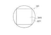
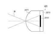
図4Aは、撮像画素221の一つを拡大して示す正面図、図7Aは断面図である。一つの撮像画素221は、マイクロレンズ2211と、光電変換部2212と、図示しないカラーフィルタから構成され、図7Aの断面図に示すように、撮像素子22の半導体回路基板2213の表面に光電変換部2212が造り込まれ、その表面にマイクロレンズ2211が形成されている。光電変換部2212は、マイクロレンズ2211により撮影光学系31の射出瞳(たとえばF1.0)を通過する撮像光束を受光する形状とされ、撮像光束IBを受光する。4A is an enlarged front view showing one of the
なお、本実施形態のカラーフィルタはマイクロレンズ2211と光電変換部2212との間に設けられ、緑画素Gと赤画素Rと青画素Bのそれぞれのカラーフィルタの分光感度は、たとえば図5に示すとおりとされている。The color filter of this embodiment is provided between the
図2及び図3に戻り、撮像素子22の撮像面の中心及び中心から左右対称位置の3箇所には、上述した撮像画素221に代えて焦点検出画素222が配列された焦点検出画素列22a,22b,22cが設けられている。図3に示すように、一つの焦点検出画素列は、複数の焦点検出画素222が横一列に配列されて構成されている。本例の焦点検出画素222は、ベイヤー配列された撮像画素221の緑画素Gと青画素Bの位置にギャップを設けることなく密に配列されている。2 and 3, focus
なお、図2に示す焦点検出画素列22a,22b,22cの位置は図示する位置にのみ限定されず、何れか一箇所又は二箇所にすることもでき、また、撮像素子22の中心から上下対称の位置に配置することもできる。また、実際の焦点検出に際しては、複数配置された焦点検出画素列22a〜22cの中から使用者の手動操作により所望の焦点検出画素列を選択することもできる。Note that the positions of the focus
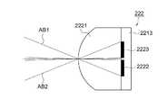
図4Bは、焦点検出画素222の一つを拡大して示す正面図、図7Bは断面図である。焦点検出画素222は、図4Bに示すように、マイクロレンズ2221と、一対の光電変換部2222,2223から構成され、図7Bの断面図に示すように、撮像素子22の半導体回路基板2213の表面に光電変換部2222,2223が造り込まれ、その表面にマイクロレンズ2221が形成されている。一対の光電変換部2222,2223は同じ大きさで、かつマイクロレンズ2221の光軸に対して左右対称に配置されている。この光電変換部2222,2223は、マイクロレンズ2221により撮影光学系31の特定の射出瞳(たとえばF2.8)を通過する一対の光束を受光する形状とされている。すなわち、図7Bに示すように、焦点検出画素222の一方の光電変換部2222は一方の光束AB1を受光する一方で、焦点検出画素222の他方の光電変換部2223は、マイクロレンズ2221の光軸に対して光束AB1と対称となる光束AB2を受光する。4B is an enlarged front view showing one of the
なお、焦点検出画素222にはカラーフィルタは設けられておらず、その分光特性は、光電変換を行うフォトダイオードの分光特性と、図示しない赤外カットフィルタの分光特性を総合したものとなっている。図6に焦点検出画素222の分光特性を示すが、相対感度は、図5に示す撮像画素221の青画素B、緑画素G及び赤画素Rの各感度を加算したような分光特性とされ、また感度が現れる光波長領域は、図5に示す撮像画素221の青画素B、緑画素G及び赤画素Rの感度の光波長領域を包摂した領域となっている。ただし、撮像画素221と同じカラーフィルタのうちの一つ、たとえば緑フィルタを備えるように構成することもできる。Note that the
また、図4Bに示す焦点検出画素222の光電変換部2222,2223は半円形状としたが、光電変換部2222,2223の形状はこれに限定されず、他の形状、たとえば、楕円形状、矩形状、多角形状にすることもできる。In addition, although the
ここで、上述した焦点検出画素222の出力に基づいて焦点を調節する、いわゆる瞳分割位相差検出方式について説明する。Here, a so-called pupil division phase difference detection method for adjusting the focus based on the output of the
図8は、図3のVIII-VIII線に沿う断面図であり、撮影光軸L上に配置された焦点検出画素222−1と、これに隣接する焦点検出画素222−2が、射出瞳34の測距瞳341,342から照射される光束AB1−1,AB2−1,AB2−1,AB2−2を受光することを示す。ただし、その他の焦点検出画素についても、一対の光電変換部は一対の測距瞳341,342から照射される一対の光束を受光する。FIG. 8 is a cross-sectional view taken along the line VIII-VIII in FIG. 3, and the focus detection pixel 222-1 disposed on the photographing optical axis L and the focus detection pixel 222-2 adjacent thereto are formed by the
ここで、射出瞳34とは、交換レンズ3の予定焦点面に配置された焦点検出画素222のマイクロレンズ2221の前方Dの位置に設定された像である。距離Dは、マイクロレンズの曲率、屈折率、マイクロレンズと光電変換部との距離などに応じて一義的に決まる値であって、この距離Dを測距瞳距離と称する。また、測距瞳341,342とは、焦点検出画素222のマイクロレンズ2221により投影された光電変換部2222,2223の像をいう。Here, the
なお、同図において焦点検出画素222−1,222−2の配列方向は一対の測距瞳341,342の並び方向と一致している。In the figure, the arrangement direction of the focus detection pixels 222-1 and 222-2 is coincident with the arrangement direction of the pair of
焦点検出画素222のマイクロレンズ2221−1,2221−2は、交換レンズ3の予定焦点面近傍に配置されており、光軸L上に配置されたマイクロレンズ2221−1により、その背後に配置された一対の光電変換部2222−1,2223−1の形状が測距瞳距離Dだけ離れた射出瞳34上に投影され、その投影形状は測距瞳341,342を形成する。The micro lenses 2221-1 and 221-2 of the
同様に、光軸L上から離間して配置されたマイクロレンズ2221−2により、その背後に配置された一対の光電変換部2222−2,2223−2の形状が測距瞳距離Dだけ離れた射出瞳34上に投影され、その投影形状は測距瞳341,342を形成する。Similarly, the shape of the pair of photoelectric conversion units 2222-2 and 2223-2 arranged behind the microlens 2221-2 arranged away from the optical axis L is separated by the distance measuring pupil distance D. Projected onto the
すなわち、測距瞳距離Dにある射出瞳34上で、各焦点検出画素222の光電変換部2222,2223の投影形状(測距瞳341,342)が一致するように各画素222の投影方向が決定されている。That is, on the
なお、焦点検出画素222−1の光電変換部2222−1は、一方の測距瞳341を通過しマイクロレンズ2221−1に向かう一方の焦点検出光束AB1−1により、マイクロレンズ2221−1上に形成される像の強度に対応した信号を出力する。これに対して、光電変換部2223−1は、他方の測距瞳342を通過しマイクロレンズ2221−1に向かう他方の焦点検出光束AB2−1により、マイクロレンズ2221−1上に形成される像の強度に対応した信号を出力する。Note that the photoelectric conversion unit 2222-1 of the focus detection pixel 222-1 is placed on the microlens 2222-1 by one focus detection light beam AB1-1 that passes through one
同様に、焦点検出画素222−2の光電変換部2222−2は、一方の測距瞳341を通過しマイクロレンズ2221−2に向かう一方の焦点検出光束AB1−2により、マイクロレンズ2221−2上に形成される像の強度に対応した信号を出力する。これに対して、光電変換部2223−2は、他方の測距瞳342を通過しマイクロレンズ2221−2に向かう他方の焦点検出光束AB2−2により、マイクロレンズ2221−2上に形成される像の強度に対応した信号を出力する。Similarly, the photoelectric conversion unit 2222-2 of the focus detection pixel 222-2 passes through one
以上の焦点検出画素222を、図3に示すように直線状に複数配置し、各焦点検出画素222の一対の光電変換部2222,2223の出力を、測距瞳341と測距瞳342のそれぞれに対応した出力グループにまとめることにより、測距瞳341と測距瞳342のそれぞれを通過する焦点検出光束AB1,AB2が焦点検出画素列上に形成する一対の像の強度分布に関するデータが得られる。この強度分布データに対し、相関演算処理又は位相差検出処理などの像ズレ検出演算処理を施すことにより、いわゆる瞳分割位相差検出方式による像ズレ量を検出することができる。A plurality of the
そして、得られた像ズレ量に一対の測距瞳の重心間隔に応じた変換演算を施すことにより、予定焦点面に対する現在の焦点面(予定焦点面上のマイクロレンズアレイの位置に対応した焦点検出位置における焦点面をいう。)の偏差、すなわちデフォーカス量を求めることができる。Then, a conversion calculation is performed on the obtained image shift amount according to the center-of-gravity interval of the pair of distance measuring pupils, thereby obtaining a current focal plane with respect to the planned focal plane (the focal point corresponding to the position of the microlens array on the planned focal plane). The deviation of the focal plane at the detection position, that is, the defocus amount can be obtained.
図1に戻り、撮像素子22には、当該撮像素子22を交換レンズ3の光軸方向に移動させる移動機構23が設けられている。この移動機構23は、圧電素子アクチュエータ、超音波モータ、ボイスコイルモータなどの各種アクチュエータで構成することができ、ハーフミラー21を光束L1の光路内に挿入した場合と退避した場合との、当該ハーフミラー21による光路長変化を調整する。Returning to FIG. 1, the
すなわち、所定厚さdを有するハーフミラー21の屈折率nはn>1であるから、ハーフミラー21を透過してできる像の位置は、ハーフミラー21がないときの像の位置に比べてハーフミラー21から離れる位置になる。この光路長の変化量δはハーフミラー21の厚さdと、屈折率nと、ハーフミラー21の傾斜角から理論的又は実験的に求めることができるので、予め求めておく。That is, since the refractive index n of the
そして、ハーフミラー21を光束L1の光路から退避した場合の撮像素子22の光軸方向の位置(図1の点線で示す位置。以下、前進位置ともいう。)は交換レンズ3の予定焦点面であることから、この位置を機械的に位置決めしておく。たとえば、機械的ストッパをカメラ本体2に固定し、撮像素子22が前進位置でこのストッパに押し当てられることにより当該前進位置が位置決めされるように構成する。The position in the optical axis direction of the
この状態からハーフミラー21を光路内に挿入した場合には、移動機構23により、同図の実線で示すように(以下、この位置を後退位置ともいう。)、撮像素子22を光軸方向の後方(使用者の方向)へ光路長の変化量δだけ移動させる。この後退位置にも機械的ストッパを設けておくことができる。そしてこの状態から、ハーフミラー21を光路から退避した場合には、移動機構23により撮像素子22を光軸方向の前方(被写体方向)へ光路長の変化量δだけ移動させる。この移動指令はカメラ制御CPU25が実行する。When the
このように、本実施形態の撮像素子22の移動動作、特にハーフミラー21を退避させて撮像素子22を前進位置に戻す動作においては、複雑な位置制御は不要であり、単純に機械的ストッパなどに押し当てて停止すればよいので、ハーフミラー21を光路中に挿入した場合に生じる像面の移動量δを、フォーカスレンズ314の移動により行う場合に比べ、高速かつ高精度に行うことができる。As described above, in the moving operation of the
なお、移動機構23による撮像素子22の移動態様は、図1に実線で示す後退位置と点線で示す前進位置という2つの位置を移動させる態様以外にも、たとえば同図の実線と点線で示す位置の中間に初期位置を設定し、この初期位置から実線で示す後退位置へ後退させたり、又は点線で示す前進位置へ前進させたりすることもできる。The moving
上述したとおりハーフミラー21を透過してできる像と透過せずにできる像の位置はハーフミラー21の厚さと屈折率が原因でずれるので、ハーフミラー21を透過してできる像に基づいて焦点調節を行ってもハーフミラー21のない状態で撮影すると焦点がずれることになる。 As described above, the position of the image that can be transmitted through the
しかしながら、本実施形態では、ハーフミラー21を透過してできる像に基づいて焦点調節を行う一方で、ハーフミラー21のない状態で撮影する際にはハーフミラー21の光路長変化量δだけ撮像素子22を光軸方向前方へ移動させるので、撮像素子22の撮像面における合焦状態が維持されることになる。However, in the present embodiment, the focus adjustment is performed based on an image that is transmitted through the
また、交換レンズ3に設けられた距離表示器33にはフォーカスレンズ314の位置に連動した被写体距離が表示されるところ、本実施形態ではハーフミラー21を光路内に挿入した状態で焦点調節状態を検出し、この焦点調節状態に応じてフォーカスレンズ314の位置を調節し、このフォーカスレンズ314の位置を距離表示器33に表示する。すなわち、ハーフミラー21を光路から退避させて撮影する状態ではフォーカスレンズ314の位置を変更しないので、距離表示器33には正確な被写体距離データが表示されることになる。The
ちなみに、本実施形態の焦点検出画素222に代えて図9及び図10に示す焦点検出画素222a,222bを用いることもできる。図9は、本発明の他の実施形態に係る画素の配列を模式的に示す正面図であり、図2のIII部に相当する拡大正面図、図10は、図9の一対の焦点検出画素を拡大して示す正面図である。Incidentally, focus
図3及び図4Bに示す実施形態では、焦点検出画素222として一つの画素に一対の光電変換部2222,2223を有するものを用いたのに対し、図9及び図10に示す実施形態では一対の焦点検出画素222a,222bのそれぞれに対をなす光電変換部2224,2225を有するものを用いる。In the embodiment shown in FIG. 3 and FIG. 4B, the
図10に示す焦点検出画素222aは、マイクロレンズ2221と、光電変換部2224から構成され、図7Bに示す断面図と同様に、撮像素子22の半導体回路基板2213の表面に光電変換部2224が造り込まれ、その表面にマイクロレンズ2221が形成されている。光電変換部2224はマイクロレンズ2221の光軸に対して左右対称の位置のうちの左側に配置されている。A
これに対して、図10に示す焦点検出画素222bも、マイクロレンズ2221と、光電変換部2225から構成され、図7Bに示す断面図と同様に、撮像素子22の半導体回路基板2213の表面に光電変換部2225が造り込まれ、その表面にマイクロレンズ2221が形成されている。光電変換部2225はマイクロレンズ2221の光軸に対して左右対称の位置のうちの右側に配置されている。On the other hand, the
そして、図9に示すように、一対の焦点検出画素222a,222bは撮像素子22の中心から左右一列に配置され、撮影光学系31の射出瞳を通過する一対の光束をこれら一対の焦点検出画素222a,222bそれぞれの光電変換部2224,2225で受光する。As shown in FIG. 9, the pair of
このように、異なる画素で構成される一対の焦点検出画素222a,222bを用いても、一対の光電変換部2224,2225の出力結果に基づいて、瞳分割位相差検出方式による像ズレ量を検出することができる。As described above, even when a pair of
これに加えて、撮像素子22を構成する画素からの出力読出回路の構成がシンプルになるという利点もある。In addition to this, there is an advantage that the configuration of the output readout circuit from the pixels constituting the
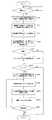
次に、本実施形態に係るカメラの動作例を説明する。図11は本実施形態に係るカメラ1の動作を示すフローチャートである。Next, an operation example of the camera according to the present embodiment will be described. FIG. 11 is a flowchart showing the operation of the
まず、ステップS100にてカメラ1の電源がONされていることを確認した上でステップS110に進み、ハーフミラー21を光路内への挿入位置へ移動させるとともに、移動機構23により撮像素子22を図1に実線で示す後退位置へ移動させる。First, in step S100, it is confirmed that the power of the
ステップS120では、ハーフミラー21が挿入位置(被写体の観察位置)にあり、また撮像素子22が後退位置にある状態で、撮像素子22の画像データをカメラ制御CPU25へ読み出すとともに、この画像データに間引き処理などを施したのち、液晶ディスプレイ27の駆動回路272を介して液晶表示素子271に現在の撮影画像を表示する。In step S120, the image data of the
なお、被写体からの光束L1の一部はハーフミラー21を通過して撮像素子22へ至る一方で、残りの光束L2はハーフミラー21で反射してスクリーン241に至るので、使用者は、ペンタプリズム242及び接眼レンズ243を介して被写体を観察できるとともに液晶ディスプレイ27によっても被写体を観察することができる。A part of the light beam L1 from the subject passes through the
ステップS130では、撮像素子22に設定された焦点検出画素列22a〜22cに設けられた焦点検出画素222から一対のデータを読み出す。この場合、使用者の手動操作により特定の焦点検出画素列が選択されているときは、その焦点検出画素列の焦点検出画素からのデータのみを読み出す。In step S130, a pair of data is read from the
ステップS140では、読み出された一対の像データに基づいて像ズレ検出演算処理(相関演算処理)を行って像ズレ量を演算し、さらにこの像ズレ量をデフォーカス量に変換する。In step S140, an image shift detection calculation process (correlation calculation process) is performed based on the read pair of image data to calculate an image shift amount, and the image shift amount is converted into a defocus amount.
ここで、読み出された一対の像データに基づく像ズレ検出演算処理(相関演算処理)の一例を簡単に説明する。Here, an example of image shift detection calculation processing (correlation calculation processing) based on the read pair of image data will be briefly described.
焦点検出画素222が検出する一対の像は、測距瞳341,342が交換レンズ3の絞り開口312により遮光され、光量バランスが崩れている可能性がある。したがって、本実施形態では、この光量バランスの崩れに対して像ズレ検出精度を維持できるタイプの相関演算を施す。In the pair of images detected by the
まず、焦点検出画素列から読み出された一対の像データ列をA11〜A1M、A21〜A2M(Mはデータ数)とし、下記相関演算式(数式1)を行い、相関量C(k)を演算する。First, a pair of image data sequences read out from the focus detection pixel sequence are A11 to A1M and A21 to A2M (M is the number of data), the following correlation calculation formula (Formula 1) is performed, and the correlation amount C (K) is calculated.
[数1]
C(k)=Σ|A1n・A2n+1+k−A2n+k・A1n+1|
なお、数式1においてΣ演算はnについての累積演算(総和演算)を示し、nの範囲は、像ずらし量kに応じてA1n、A1n+1、A2n+k、A2n+1+kのデータが存在する範囲に限定される。また、像ずらし量kは整数であり、データ列のデータ間隔を単位とした相対的シフト量である。[Equation 1]
C (k) = Σ | A1n · A2n + 1 + k −A2n + k · A1n + 1 |
In
数式1の演算結果は、図12(a)に示すように、一対のデータの相関が高いシフト量(図12(a)ではk=kj=2)において相関量C(k)が極小(小さいほど相関度が高い)になる。 As shown in FIG. 12A, the calculation result of
次に、数式2〜数式5による3点内挿の手法を用いて、連続的な相関量に対する極小値C(x)を与えるシフト量xを求める。Next, the shift amount x that gives the minimum value C (x) with respect to the continuous correlation amount is obtained by using the three-point interpolation method according to
[数2]
x=kj+D/SLOP[Equation 2]
x = kj + D / SLOP
[数3]
C(x)= C(kj)−|D|[Equation 3]
C (x) = C (kj)-| D |
[数4]
D={C(kj−1)−C(k j+1)}/2[Equation 4]
D = {C (kj-1) -C (kj + 1)} / 2
[数5]
SLOP=MAX{C(kj+1)−C(kj),C(kj−1)−C(kj)}
そして、数式2で算出されたシフト量xの信頼性があるかどうかは、以下のようにして判定する。[Equation 5]
SLOP = MAX {C (kj + 1) -C (kj), C (kj-1) -C (kj)}
Then, whether or not the shift amount x calculated by
図12(b)に示すように、一対のデータの相関度が低い場合は、内挿された相関量の極小値C(x)の値が大きくなる。したがって、C(x)が所定の閾値以上の場合は算出されたシフト量の信頼性が低いと判定し、算出されたシフト量xをキャンセルする。As shown in FIG. 12B, when the degree of correlation between a pair of data is low, the minimum value C (x) of the interpolated correlation amount increases. Therefore, when C (x) is equal to or greater than a predetermined threshold value, it is determined that the reliability of the calculated shift amount is low, and the calculated shift amount x is canceled.
または、C(x)をデータのコントラストで規格化するために、コントラストに比例した値となるSLOPでC(x)を除した値が所定値以上の場合は、算出されたシフト量の信頼性が低いと判定し、算出されたシフト量xをキャンセルする。Alternatively, in order to normalize C (x) with the contrast of data, when the value obtained by dividing C (x) by SLOP that is proportional to the contrast is equal to or greater than a predetermined value, the reliability of the calculated shift amount Is determined to be low, and the calculated shift amount x is canceled.
または、コントラストに比例した値となるSLOPが所定値以下の場合は、被写体が低コントラストであり、算出されたシフト量の信頼性が低いと判定し、算出されたシフト量xをキャンセルする。Alternatively, when SLOP that is proportional to the contrast is equal to or less than a predetermined value, it is determined that the subject has low contrast and the reliability of the calculated shift amount is low, and the calculated shift amount x is canceled.
また、図12(c)に示すように、一対のデータの相関度が低く、シフト範囲kmin〜kmaxの間で相関量C(k)の落ち込みがない場合は、極小値C(x)を求めることができず、このような場合は焦点検出不能と判定する。As shown in FIG. 12C, when the correlation between the pair of data is low and there is no drop in the correlation amount C (k) between the shift ranges kmin to kmax, the minimum value C (x) is obtained. In such a case, it is determined that the focus cannot be detected.
なお、相関演算式としては上述した数式1に限定されず他の公知の相関式を利用することもできる。The correlation calculation formula is not limited to
算出されたシフト量xの信頼性があると判定された場合は、下記数式6により像ズレ量shftを求める。 When it is determined that the calculated shift amount x is reliable, the image shift amount shft is obtained by the following formula 6.
[数6]
shft=PY・x
数式6において、PYは検出ピッチ(焦点検出画素のピッチ)である。[Equation 6]
shft = PY · x
In Expression 6, PY is a detection pitch (pitch of focus detection pixels).
最後に、数式6で算出された像ズレ量shftに所定の変換係数kを乗じてデフォーカス量defを求める。Finally, the defocus amount def is obtained by multiplying the image shift amount shft calculated by Expression 6 by a predetermined conversion coefficient k.
[数7]
def=k・shft
図11のステップS150へ戻り、ステップS140で算出されたデフォーカス量の絶対値が所定値以内であるか否かを判断する。デフォーカス量の絶対値が所定値以内にあるときは合焦しているものとし、ステップS160をジャンプしてステップS170へ進む。デフォーカス量が所定値以内にないときは、ステップS160へ進み、カメラ制御CPU25からレンズ制御CPU32を介してレンズ駆動モータ34へ駆動信号を送出し、フォーカスレンズ314を合焦位置へ移動させる。これと相前後してフォーカスレンズ314の合焦位置に連動した被写体距離を距離表示器33に表示する。[Equation 7]
def = k · shft
Returning to step S150 in FIG. 11, it is determined whether or not the absolute value of the defocus amount calculated in step S140 is within a predetermined value. When the absolute value of the defocus amount is within the predetermined value, it is assumed that the in-focus state is achieved, and the process jumps to step S160 and proceeds to step S170. When the defocus amount is not within the predetermined value, the process proceeds to step S160, where a drive signal is sent from the
なお、ステップS150にて焦点検出が不能であると判断された場合もこのステップS160へ進み、レンズ制御CPU32にスキャン駆動命令を送信し、交換レンズ3のフォーカスレンズ314を無限端から至近端の間でスキャン駆動させることで合焦位置を探索したのち、ステップS100へ戻って上記動作を繰り返す。If it is determined in step S150 that focus detection is impossible, the process proceeds to step S160, where a scan drive command is transmitted to the
ステップS170では、カメラ本体2に設けられた図示しないレリーズボタンが押されたか否かを判断する。レリーズボタンが押されないときはステップS100へ戻り、ステップS100〜S170の処理を繰り返す。 In step S170, it is determined whether or not a release button (not shown) provided on the
ステップS170でレリーズボタンが押されたことを検出したら、ステップS180へ進み、ハーフミラー21を光束L1の光路から退避させると同時に、移動機構23を制御して撮像素子22を光路長変化量δだけ光軸方向に前進させる。ハーフミラー21の退避動作により撮影光学系31による像面はδだけ前方にずれるので、撮像素子22の撮像面を前方に移動する。 If it is detected in step S170 that the release button has been pressed, the process proceeds to step S180, where the
これにより、再びフォーカスレンズ314を移動させることなく、撮像素子22の撮像面における焦点調節状態が維持されることになる。その結果、レリーズボタンを押した後にフォーカスレンズ314が動作するといった違和感を使用者に与えることがなくなる。Thereby, the focus adjustment state on the imaging surface of the
ステップS190では、レンズ制御CPU32に対して絞り調整命令を送信し、交換レンズ3の絞り312の絞り値を、使用者または自動設定された制御F値にする。この絞り制御が終了したのち、撮像素子22の撮像画素221および全ての焦点検出画素222から画像データを読み出す。 In step S190, an aperture adjustment command is transmitted to the
ここで、読み出された焦点検出画素222の画像データは白黒データであることから、ステップS200にて、焦点検出画素列22a〜22cの各焦点検出画素222が位置する画素データを、これら焦点検出画素222の周囲の撮像画素221の画像データに基づいて画素補間する。これにより、焦点検出画素列22a〜22cの位置におけるカラー画像データを得ることができる。 Here, since the read image data of the
最後に、ステップS210にて、撮像画素221の画像データおよび補間された画像データをメモリ26に保存する。このとき、得られた画像データを間引き処理して液晶ディスプレイ27に表示することもできる。Finally, in step S210, the image data of the
ステップS220では連続撮影かどうかを判断し、連続撮影の場合にはステップS190〜S210を繰り返す。なお、連続撮影モードはカメラ本体2などに設けられる連続撮影モードスイッチを使用者が操作することで選択される。In step S220, it is determined whether or not continuous shooting is performed, and in the case of continuous shooting, steps S190 to S210 are repeated. The continuous shooting mode is selected by the user operating a continuous shooting mode switch provided in the
連続撮影モードが選択されているときは、ハーフミラー21のアップ・ダウンを行うことなくハーフミラー21を退避位置に退避させた状態で撮像素子22からの画像データを連続して読み出すので、連続撮影の駒速度を上げることができる。なお、ハーフミラー21が退避位置にあると観察光学系24による被写体の観察はできないが、上述したように液晶ディスプレイ27に画像データを表示させることにより使用者は被写体を観察しながら連続撮影を行うことができる。When the continuous shooting mode is selected, the image data from the
図13は、本発明の他の実施形態に係るカメラの動作例を示すフローチャートである。図11に示す実施形態の動作フローに対して、ステップS180とS190の間にステップS182,S186,S188を追加した動作フローであり、共通する動作フローについては説明を省略する。FIG. 13 is a flowchart showing an operation example of a camera according to another embodiment of the present invention. This is an operation flow in which steps S182, S186, and S188 are added between steps S180 and S190 with respect to the operation flow of the embodiment shown in FIG. 11, and the description of the common operation flow is omitted.
上述した実施形態では、レリーズボタンが押されたらハーフミラー21を退避させるとともに撮像素子22を前進させた後、フォーカスレンズ314の焦点調節動作を行わずに撮像動作を行っている。これに対して、本実施形態では撮像素子22を前進させてから撮像動作するまでの間にフォーカスレンズ314の焦点調節動作を再度行うようにしている。In the above-described embodiment, when the release button is pressed, the
すなわち、ステップS180にて、ハーフミラー21を光束L1の光路から退避させると同時に、移動機構23を制御して撮像素子22を光路長変化量δだけ光軸方向に前進させたら、ステップS182へ進み、撮像素子22に設定された焦点検出画素列22a〜22cに設けられた焦点検出画素222から一対のデータを読み出す。この場合、使用者の手動操作により特定の焦点検出画素列が選択されているときは、その焦点検出画素列の焦点検出画素からのデータのみを読み出す。That is, in step S180, the
次のステップS184では、読み出された一対の像データに基づいて像ズレ検出演算処理(相関演算処理)を行って像ズレ量を演算し、さらにこの像ズレ量をデフォーカス量に変換する。この像ズレ量の演算とデフォーカス量の算出は、上述したステップS140と同じである。In the next step S184, an image shift detection calculation process (correlation calculation process) is performed based on the read pair of image data to calculate an image shift amount, and this image shift amount is converted into a defocus amount. The calculation of the image shift amount and the calculation of the defocus amount are the same as in step S140 described above.
次のステップS186では、ステップS184で算出されたデフォーカス量の絶対値が所定値以内であるか否かを判断する。デフォーカス量の絶対値が所定値以内にあるときは合焦しているものとし、ステップS188をジャンプしてステップS190へ進む。デフォーカス量が所定値以内にないときは、ステップS188へ進み、カメラ制御CPU25からレンズ制御CPU32を介してレンズ駆動モータ34へ駆動信号を送出し、フォーカスレンズ314を合焦位置へ移動させる。これと相前後してフォーカスレンズ314の合焦位置に連動した被写体距離を距離表示器33に表示する。In the next step S186, it is determined whether or not the absolute value of the defocus amount calculated in step S184 is within a predetermined value. When the absolute value of the defocus amount is within the predetermined value, it is assumed that the in-focus state is achieved, and the process jumps to step S188 and proceeds to step S190. If the defocus amount is not within the predetermined value, the process proceeds to step S188, where a drive signal is sent from the
本実施形態では、ハーフミラー21を退避させるとともに撮像素子22を光路長変化量δだけ前進させたのちに、再度フォーカスレンズ314の合焦操作を行うので、撮像素子22の移動動作や光路長変化量δに多少の誤差があっても確実に合焦した画像データを得ることができる。In this embodiment, since the
なお、ステップS180の撮像素子22の前進移動によって既に合焦位置の近傍に移動しているので、このステップS188の焦点調節動作は、使用者に違和感を与えるほど大きな移動量ではなくまた迅速に行うことができる。Note that since the
さて、上述した図11及び図13のステップS110においては、移動機構23を制御して撮像素子22を、基準位置からハーフミラーを光路中に挿入した場合に生じる像面の移動量、すなわち光路長変化量δだけ移動させる。しかしながら、ハーフミラー21を光路中に挿入した場合に生じる像面の移動量(光路長変化量δ)は、像を形成する光束の収差に応じて変化するために、交換レンズ3の絞り開口F値や焦点検出画素列22a〜22cの、画面中心からの像高位置によって変化する。Now, in step S110 of FIG. 11 and FIG. 13 described above, the moving
そこで、本発明の他の実施形態として、図11及び図13のステップS110において、ボディ制御CPU25は交換レンズ3のレンズ制御CPU32との通信によって絞り開口F値の情報を得るとともに、使用者等により選択された焦点検出画素列22a〜22cの位置を取得し、これら絞り開口F値及び焦点検出位置に応じて表1のように光路長変化量mを決定し、決定された光路長変化量δmだけ撮像素子22を移動させるようにしてもよい。 Therefore, as another embodiment of the present invention, in step S110 of FIG. 11 and FIG. 13, the

このようにすれば、交換レンズ3の絞り開口F値や焦点検出位置によらず、より高精度な焦点調節を達成した状態での撮影が可能になる。In this way, it is possible to perform shooting in a state in which more accurate focus adjustment is achieved regardless of the aperture value F value of the
また同様に、光路長変化量δmを算出するに際には、表1に限定されずその他の情報、たとえば焦点距離、射出瞳距離又は色収差(分光感度特性)などを用いることもできる。Similarly, when calculating the optical path length variation δm, other information such as a focal length, an exit pupil distance, or chromatic aberration (spectral sensitivity characteristic) can be used without being limited to Table 1.
なお、上述したようにハーフミラー21が挿入位置にあるときの撮像素子22の光軸方向の位置が状況に応じて変化する場合、撮像素子22の移動量に拘らず常に撮像素子22の位置と共役な面にスクリーン241が位置するようにスクリーン241を移動させてもよい。撮像素子22の移動量に応じてスクリーン241を移動させることにより観察光学系24により観察される被写体像も正確に合焦することになる。 As described above, when the position of the
また、圧電素子などのアクチュエータで構成することができる移動機構23は、撮像素子22を光軸方向に移動させる機能を有するので、これを利用して当該移動機構23を他の用途にも使用することが可能である。たとえば、移動機構23により撮像素子22を光軸方向に高い周波数で振動させることにより、撮像素子22の表面に付着したゴミをふるい落とすこともできる。 Moreover, since the moving
また、上述した実施形態では、撮像素子22に組み込まれた瞳分割型の焦点検出画素222の出力信号に応じて、いわゆる位相差検出方式で焦点検出を行うように構成したが、これ以外にも撮像素子22の出力信号を用いてコントラスト検出を行い、このコントラスト評価結果に応じて、いわゆる山登り方式で自動焦点調節を行うように構成することもできる。 In the above-described embodiment, the focus detection is performed by the so-called phase difference detection method in accordance with the output signal of the pupil-divided
本実施形態の撮像装置1は、上述した一眼レフデジタルカメラに限定されず、銀塩フィルムカメラ、レンズ一体型デジタルスチルカメラや銀塩フィルムスチルカメラのほかビデオカメラにも適用できる。また、携帯電話機などに内蔵される小型カメラモジュール、監視カメラ、ロボット用視覚認識装置等にも適用できる。さらに、カメラ以外のたとえば焦点検出装置、測距装置、ステレオ測距装置などにも適用することができる。 The
1…一眼レフデジタルカメラ;2…カメラ本体;3…交換レンズ
21…ハーフミラー;22…撮像素子;23…移動機構;25…カメラ制御CPU
32…レンズ制御CPU;33…距離表示器
221…撮像画素;222,222a,222b…焦点検出画素
2221…マイクロレンズ;2222〜2225…光電変換部
314…フォーカスレンズDESCRIPTION OF
32 ... Lens control CPU; 33 ...
Claims (9)
Translated fromJapanese前記撮影光学系と前記撮像素子との間の光路中に挿脱可能に設けられたハーフミラーと、
前記受光信号に基づいて前記撮影光学系の焦点調節状態を検出する検出手段と、
前記検出手段により検出された焦点調節状態に応じて前記撮影光学系を駆動して前記焦点調節状態を調節する焦点調節手段と、
前記ハーフミラーの挿脱に応じた移動量で前記撮像素子を移動する移動手段と、を備えることを特徴とする撮像装置。An image sensor in which a plurality of pixels that receive a light beam through the photographing optical system and output a light reception signal are arranged;
A half mirror provided in an optical path between the imaging optical system and the image sensor so as to be insertable and removable;
Detecting means for detecting a focus adjustment state of the photographing optical system based on the light reception signal;
Focus adjusting means for adjusting the focus adjustment state by driving the imaging optical system according to the focus adjustment state detected by the detection means;
An image pickup apparatus comprising: moving means for moving the image pickup element by a movement amount corresponding to insertion / removal of the half mirror.
前記焦点調節手段は、前記ハーフミラーが前記光路中に挿入された状態で前記撮影光学系の焦点を調節することを特徴とする撮像装置。The imaging device according to claim 1,
The imaging apparatus, wherein the focus adjusting unit adjusts the focus of the photographing optical system in a state where the half mirror is inserted in the optical path.
前記撮像素子は、前記撮影光学系の瞳の異なる領域からの光を受光する光電変換部を有する焦点検出画素を備え、
前記検出手段は、前記焦点検出画素からの信号に基づき前記異なる領域からの光による像のズレ量を検出することを特徴とする撮像装置。The imaging apparatus according to claim 1 or 2,
The imaging element includes a focus detection pixel having a photoelectric conversion unit that receives light from different regions of the pupil of the photographing optical system,
The image pickup apparatus, wherein the detection unit detects an image shift amount due to light from the different regions based on a signal from the focus detection pixel.
前記移動手段は、前記撮影光学系の特性に応じた移動量で前記撮像素子を移動することを特徴とする撮像装置。In the imaging device according to any one of claims 1 to 3,
The image pickup apparatus, wherein the moving means moves the image pickup device by a moving amount corresponding to a characteristic of the photographing optical system.
前記移動手段は、前記撮影光学系の絞り開口F値に応じた移動量で前記撮像素子を移動することを特徴とする撮像装置。The imaging apparatus according to claim 4.
The image pickup apparatus, wherein the moving means moves the image pickup element by a moving amount corresponding to a diaphragm aperture F value of the photographing optical system.
前記移動手段は、前記撮影光学系の像の分光感度特性に応じた移動量で前記撮像素子を移動することを特徴とする撮像装置。The imaging apparatus according to claim 4.
The image pickup apparatus, wherein the moving unit moves the image pickup element by a moving amount corresponding to a spectral sensitivity characteristic of an image of the photographing optical system.
前記移動手段は、前記撮影光学系の像面内の、前記検出手段による焦点調節状態の検出位置に応じた移動量で前記撮像素子を移動することを特徴とする撮像装置。In the imaging device according to any one of claims 1 to 6,
The image pickup apparatus characterized in that the moving means moves the image pickup element by an amount of movement corresponding to a detection position of a focus adjustment state by the detecting means within an image plane of the photographing optical system.
前記撮影光学系の位置に応じた撮影距離を表示する距離表示手段をさらに備えることを特徴とする撮像装置。In the imaging device according to any one of claims 1 to 7,
An imaging apparatus, further comprising distance display means for displaying an imaging distance corresponding to a position of the imaging optical system.
前記移動手段は、前記撮像素子を振動させる加振手段であることを特徴とする撮像装置。In the imaging device according to any one of claims 1 to 8,
The image pickup apparatus, wherein the moving means is a vibration means for vibrating the image pickup device.
Priority Applications (1)
| Application Number | Priority Date | Filing Date | Title |
|---|---|---|---|
| JP2007247392AJP2009081522A (en) | 2007-09-25 | 2007-09-25 | Imaging device |
Applications Claiming Priority (1)
| Application Number | Priority Date | Filing Date | Title |
|---|---|---|---|
| JP2007247392AJP2009081522A (en) | 2007-09-25 | 2007-09-25 | Imaging device |
Publications (1)
| Publication Number | Publication Date |
|---|---|
| JP2009081522Atrue JP2009081522A (en) | 2009-04-16 |
Family
ID=40655976
Family Applications (1)
| Application Number | Title | Priority Date | Filing Date |
|---|---|---|---|
| JP2007247392APendingJP2009081522A (en) | 2007-09-25 | 2007-09-25 | Imaging device |
Country Status (1)
| Country | Link |
|---|---|
| JP (1) | JP2009081522A (en) |
Cited By (3)
| Publication number | Priority date | Publication date | Assignee | Title |
|---|---|---|---|---|
| JP2011018056A (en)* | 2008-01-25 | 2011-01-27 | Sony Corp | Imaging apparatus, imaging apparatus control method, and program |
| JP2011028177A (en)* | 2009-07-29 | 2011-02-10 | Nikon Corp | Imaging apparatus |
| EP2511761A3 (en)* | 2011-04-14 | 2014-08-27 | Canon Kabushiki Kaisha | Image pickup apparatus and ND filter |
Citations (7)
| Publication number | Priority date | Publication date | Assignee | Title |
|---|---|---|---|---|
| JPH0410777A (en)* | 1990-04-27 | 1992-01-14 | Hitachi Ltd | Depth of field control device for imaging device |
| JP2000162495A (en)* | 1998-09-25 | 2000-06-16 | Asahi Optical Co Ltd | SLR digital still camera |
| JP2001100308A (en)* | 1999-09-29 | 2001-04-13 | Minolta Co Ltd | Digital camera |
| JP2005159711A (en)* | 2003-11-26 | 2005-06-16 | Konica Minolta Photo Imaging Inc | Imaging apparatus |
| JP2005326494A (en)* | 2004-05-12 | 2005-11-24 | Olympus Corp | Image microscope |
| JP2007189312A (en)* | 2006-01-11 | 2007-07-26 | Nikon Corp | Imaging apparatus, imaging method, and camera |
| JP2007199551A (en)* | 2006-01-30 | 2007-08-09 | Cosina Co Ltd | Imaging apparatus |
- 2007
- 2007-09-25JPJP2007247392Apatent/JP2009081522A/enactivePending
Patent Citations (7)
| Publication number | Priority date | Publication date | Assignee | Title |
|---|---|---|---|---|
| JPH0410777A (en)* | 1990-04-27 | 1992-01-14 | Hitachi Ltd | Depth of field control device for imaging device |
| JP2000162495A (en)* | 1998-09-25 | 2000-06-16 | Asahi Optical Co Ltd | SLR digital still camera |
| JP2001100308A (en)* | 1999-09-29 | 2001-04-13 | Minolta Co Ltd | Digital camera |
| JP2005159711A (en)* | 2003-11-26 | 2005-06-16 | Konica Minolta Photo Imaging Inc | Imaging apparatus |
| JP2005326494A (en)* | 2004-05-12 | 2005-11-24 | Olympus Corp | Image microscope |
| JP2007189312A (en)* | 2006-01-11 | 2007-07-26 | Nikon Corp | Imaging apparatus, imaging method, and camera |
| JP2007199551A (en)* | 2006-01-30 | 2007-08-09 | Cosina Co Ltd | Imaging apparatus |
Cited By (4)
| Publication number | Priority date | Publication date | Assignee | Title |
|---|---|---|---|---|
| JP2011018056A (en)* | 2008-01-25 | 2011-01-27 | Sony Corp | Imaging apparatus, imaging apparatus control method, and program |
| JP2011028177A (en)* | 2009-07-29 | 2011-02-10 | Nikon Corp | Imaging apparatus |
| EP2511761A3 (en)* | 2011-04-14 | 2014-08-27 | Canon Kabushiki Kaisha | Image pickup apparatus and ND filter |
| US8922698B2 (en) | 2011-04-14 | 2014-12-30 | Canon Kabushiki Kaisha | Image pickup apparatus with removable ND filter |
Similar Documents
| Publication | Publication Date | Title |
|---|---|---|
| JP5211714B2 (en) | Imaging device | |
| JP5256675B2 (en) | Imaging device | |
| WO2010001641A1 (en) | Focal point detection device | |
| JP2009141390A (en) | Imaging device and imaging apparatus | |
| JP5029334B2 (en) | Manufacturing method of imaging apparatus | |
| JP6642628B2 (en) | Imaging device and imaging device | |
| JP2012113189A (en) | Imaging apparatus | |
| JP2010128205A (en) | Imaging apparatus | |
| JP5206292B2 (en) | Imaging apparatus and image recording method | |
| JP5206293B2 (en) | Imaging apparatus and image recording method | |
| JP2009198771A (en) | Focus detector and imaging device | |
| JP5845660B2 (en) | Focus detection apparatus and imaging apparatus | |
| JP2009081522A (en) | Imaging device | |
| JP6561437B2 (en) | Focus adjustment device and imaging device | |
| JP5610005B2 (en) | Imaging device | |
| JP2013003486A (en) | Focus detector and imaging apparatus | |
| JP6399140B2 (en) | Imaging device | |
| JP2013122494A (en) | Focus detector and camera | |
| JP2014074851A (en) | Focus detection device and image capturing device | |
| JP2018180135A (en) | Imaging device | |
| JP2021165853A (en) | Lens barrel | |
| JP6183482B2 (en) | Focus detection apparatus and imaging apparatus | |
| JP2019095810A (en) | Focus adjustment device and imaging device | |
| JP6349624B2 (en) | Image sensor and focus detection apparatus | |
| JP2014235211A (en) | Imaging device |
Legal Events
| Date | Code | Title | Description |
|---|---|---|---|
| A621 | Written request for application examination | Free format text:JAPANESE INTERMEDIATE CODE: A621 Effective date:20100903 | |
| A977 | Report on retrieval | Free format text:JAPANESE INTERMEDIATE CODE: A971007 Effective date:20111215 | |
| A131 | Notification of reasons for refusal | Free format text:JAPANESE INTERMEDIATE CODE: A131 Effective date:20111220 | |
| A521 | Request for written amendment filed | Free format text:JAPANESE INTERMEDIATE CODE: A523 Effective date:20120217 | |
| A02 | Decision of refusal | Free format text:JAPANESE INTERMEDIATE CODE: A02 Effective date:20120529 |