JP2009080761A - Information reader, and information reading method - Google Patents
Information reader, and information reading methodDownload PDFInfo
- Publication number
- JP2009080761A JP2009080761AJP2007251247AJP2007251247AJP2009080761AJP 2009080761 AJP2009080761 AJP 2009080761AJP 2007251247 AJP2007251247 AJP 2007251247AJP 2007251247 AJP2007251247 AJP 2007251247AJP 2009080761 AJP2009080761 AJP 2009080761A
- Authority
- JP
- Japan
- Prior art keywords
- antenna
- information
- chip
- contact type
- reader
- Prior art date
- Legal status (The legal status is an assumption and is not a legal conclusion. Google has not performed a legal analysis and makes no representation as to the accuracy of the status listed.)
- Pending
Links
Images


Classifications
- G—PHYSICS
- G06—COMPUTING OR CALCULATING; COUNTING
- G06K—GRAPHICAL DATA READING; PRESENTATION OF DATA; RECORD CARRIERS; HANDLING RECORD CARRIERS
- G06K7/00—Methods or arrangements for sensing record carriers, e.g. for reading patterns
- G06K7/10—Methods or arrangements for sensing record carriers, e.g. for reading patterns by electromagnetic radiation, e.g. optical sensing; by corpuscular radiation
- G06K7/10009—Methods or arrangements for sensing record carriers, e.g. for reading patterns by electromagnetic radiation, e.g. optical sensing; by corpuscular radiation sensing by radiation using wavelengths larger than 0.1 mm, e.g. radio-waves or microwaves
- G06K7/10316—Methods or arrangements for sensing record carriers, e.g. for reading patterns by electromagnetic radiation, e.g. optical sensing; by corpuscular radiation sensing by radiation using wavelengths larger than 0.1 mm, e.g. radio-waves or microwaves using at least one antenna particularly designed for interrogating the wireless record carriers
- G06K7/10346—Methods or arrangements for sensing record carriers, e.g. for reading patterns by electromagnetic radiation, e.g. optical sensing; by corpuscular radiation sensing by radiation using wavelengths larger than 0.1 mm, e.g. radio-waves or microwaves using at least one antenna particularly designed for interrogating the wireless record carriers the antenna being of the far field type, e.g. HF types or dipoles
- G—PHYSICS
- G06—COMPUTING OR CALCULATING; COUNTING
- G06K—GRAPHICAL DATA READING; PRESENTATION OF DATA; RECORD CARRIERS; HANDLING RECORD CARRIERS
- G06K19/00—Record carriers for use with machines and with at least a part designed to carry digital markings
- G06K19/04—Record carriers for use with machines and with at least a part designed to carry digital markings characterised by the shape
- G06K19/041—Constructional details
- G06K19/042—Constructional details the record carrier having a form factor of a credit card and including a small sized disc, e.g. a CD or DVD
- G06K19/045—Constructional details the record carrier having a form factor of a credit card and including a small sized disc, e.g. a CD or DVD the record carrier being of the non-contact type, e.g. RFID, and being specially adapted for attachment to a disc, e.g. a CD or DVD
- G—PHYSICS
- G06—COMPUTING OR CALCULATING; COUNTING
- G06K—GRAPHICAL DATA READING; PRESENTATION OF DATA; RECORD CARRIERS; HANDLING RECORD CARRIERS
- G06K19/00—Record carriers for use with machines and with at least a part designed to carry digital markings
- G06K19/06—Record carriers for use with machines and with at least a part designed to carry digital markings characterised by the kind of the digital marking, e.g. shape, nature, code
- G06K19/067—Record carriers with conductive marks, printed circuits or semiconductor circuit elements, e.g. credit or identity cards also with resonating or responding marks without active components
- G06K19/07—Record carriers with conductive marks, printed circuits or semiconductor circuit elements, e.g. credit or identity cards also with resonating or responding marks without active components with integrated circuit chips
- G06K19/0723—Record carriers with conductive marks, printed circuits or semiconductor circuit elements, e.g. credit or identity cards also with resonating or responding marks without active components with integrated circuit chips the record carrier comprising an arrangement for non-contact communication, e.g. wireless communication circuits on transponder cards, non-contact smart cards or RFIDs
- G—PHYSICS
- G06—COMPUTING OR CALCULATING; COUNTING
- G06K—GRAPHICAL DATA READING; PRESENTATION OF DATA; RECORD CARRIERS; HANDLING RECORD CARRIERS
- G06K19/00—Record carriers for use with machines and with at least a part designed to carry digital markings
- G06K19/06—Record carriers for use with machines and with at least a part designed to carry digital markings characterised by the kind of the digital marking, e.g. shape, nature, code
- G06K19/067—Record carriers with conductive marks, printed circuits or semiconductor circuit elements, e.g. credit or identity cards also with resonating or responding marks without active components
- G06K19/07—Record carriers with conductive marks, printed circuits or semiconductor circuit elements, e.g. credit or identity cards also with resonating or responding marks without active components with integrated circuit chips
- G06K19/077—Constructional details, e.g. mounting of circuits in the carrier
- G06K19/07749—Constructional details, e.g. mounting of circuits in the carrier the record carrier being capable of non-contact communication, e.g. constructional details of the antenna of a non-contact smart card
- G—PHYSICS
- G06—COMPUTING OR CALCULATING; COUNTING
- G06K—GRAPHICAL DATA READING; PRESENTATION OF DATA; RECORD CARRIERS; HANDLING RECORD CARRIERS
- G06K7/00—Methods or arrangements for sensing record carriers, e.g. for reading patterns
- G06K7/10—Methods or arrangements for sensing record carriers, e.g. for reading patterns by electromagnetic radiation, e.g. optical sensing; by corpuscular radiation
- G06K7/10009—Methods or arrangements for sensing record carriers, e.g. for reading patterns by electromagnetic radiation, e.g. optical sensing; by corpuscular radiation sensing by radiation using wavelengths larger than 0.1 mm, e.g. radio-waves or microwaves
- G06K7/10158—Methods or arrangements for sensing record carriers, e.g. for reading patterns by electromagnetic radiation, e.g. optical sensing; by corpuscular radiation sensing by radiation using wavelengths larger than 0.1 mm, e.g. radio-waves or microwaves methods and means used by the interrogation device for reliably powering the wireless record carriers using an electromagnetic interrogation field
- G06K7/10178—Methods or arrangements for sensing record carriers, e.g. for reading patterns by electromagnetic radiation, e.g. optical sensing; by corpuscular radiation sensing by radiation using wavelengths larger than 0.1 mm, e.g. radio-waves or microwaves methods and means used by the interrogation device for reliably powering the wireless record carriers using an electromagnetic interrogation field including auxiliary means for focusing, repeating or boosting the electromagnetic interrogation field
Landscapes
- Engineering & Computer Science (AREA)
- Physics & Mathematics (AREA)
- General Physics & Mathematics (AREA)
- Theoretical Computer Science (AREA)
- Electromagnetism (AREA)
- Health & Medical Sciences (AREA)
- Toxicology (AREA)
- Computer Networks & Wireless Communication (AREA)
- Microelectronics & Electronic Packaging (AREA)
- Computer Hardware Design (AREA)
- General Health & Medical Sciences (AREA)
- Artificial Intelligence (AREA)
- Computer Vision & Pattern Recognition (AREA)
- Near-Field Transmission Systems (AREA)
Abstract
Description
Translated fromJapanese本発明は、非接触型ICチップに記録された情報を読み取る情報読み取り装置、および情報読み取り方法に関し、特に、非接触型ICチップに記録された情報を読み取る、携帯型の情報読み取り装置、および情報読み取り方法に関する。 The present invention relates to an information reading apparatus and an information reading method for reading information recorded on a non-contact type IC chip, and in particular, a portable information reading apparatus and information for reading information recorded on a non-contact type IC chip. It relates to the reading method.
近年、映像などの大容量データを記録可能な記録媒体として、CD(Compact Disc)、DVD(Digital Versatile Disk)などの光ディスクが広く普及している。また、光ディスクとしては、ROM(Read Only Memory)型と呼ばれる再生専用ディスクだけでなく、“Recordable”と呼ばれる追記型ディスクや“ReWritable”と呼ばれる書き換え型ディスクも一般的となっている。 In recent years, optical discs such as CD (Compact Disc) and DVD (Digital Versatile Disk) are widely used as recording media capable of recording large-capacity data such as video. Further, as an optical disc, not only a read-only disc called ROM (Read Only Memory) type but also a write-once disc called “Recordable” and a rewritable disc called “ReWritable” are common.
この光ディスクは、非常に大量のデータを安価に記録可能であることから、プログラムやデータの記録や頒布の他、音楽ソフトおよび映像ソフトの頒布や、放送内容の録音や録画などの音声データおよび映像データの記録に広く用いられている。 Since this optical disc can record a very large amount of data at a low cost, recording and distribution of programs and data, as well as distribution of music and video software, and audio data and video such as recording and recording of broadcast contents Widely used for data recording.
一方、端末側のリーダ/ライタとの間において、非接触で情報の受け渡しが可能な非接触型IC(Integrated Circuit)チップは、端末装置との通信時に物理的接触が不要という要因などによって接続開始から接続終了までの処理時間を短くでき、また、高度な相互認証および暗号処理による高いセキュリティを持つといった特徴を有している。このため、電子マネーや交通乗車券、入館証などの用途で普及が進んでいる。 On the other hand, non-contact IC (Integrated Circuit) chips that can exchange information without contact with the reader / writer on the terminal side have started connection due to factors such as no physical contact required when communicating with the terminal device The processing time from the connection to the end of the connection can be shortened, and high security is provided by advanced mutual authentication and cryptographic processing. For this reason, it is spreading in applications such as electronic money, transportation tickets, and admission cards.
そして、このような優れた特徴を持つ非接触型ICチップを、光ディスクの基板上に搭載することが従来から考えられている。例えば、2枚のディスク基板のそれぞれに凹部を形成したうえで、ディスク基板を貼り合わせたときにそれぞれの凹部の間に形成される間隙に、ICチップやその送受信用のアンテナを一体のモジュールとして配置した光ディスクが考えられている(例えば、特許文献1参照)。これにより、光ディスクプレーヤにセットして光ディスクにアクセスすることなく、光ディスクの記録内容を確認することができる。 Conventionally, it has been considered to mount a non-contact type IC chip having such excellent characteristics on a substrate of an optical disk. For example, an IC chip and an antenna for transmitting and receiving the IC chip are integrated into a gap formed between the concave portions when the disc substrates are bonded to each other after the concave portions are formed on the two disc substrates. An arranged optical disk is considered (see, for example, Patent Document 1). As a result, it is possible to check the recorded contents of the optical disc without setting the optical disc player and accessing the optical disc.
また、多数配置された物品に付されたタグに記録された情報を読み取って、物品を管理する技術が知られている。例えば、物品に添設された情報タグに記録されている物品の情報を読み取って物品の配置を検査する情報検査装置が考えられている(例えば、特許文献2参照)。 There is also known a technique for managing an article by reading information recorded on a tag attached to a large number of arranged articles. For example, an information inspection apparatus that inspects the arrangement of an article by reading the information of the article recorded in an information tag attached to the article is considered (for example, see Patent Document 2).
ところで、非接触型ICチップとリーダ/ライタとの間では、それぞれが備えているアンテナによって電磁波を用いて通信を行っている。しかし、それぞれのアンテナの形状によっては、電磁波の特性上、送受信の際に指向性が生じる場合があるため、各アンテナが発生する電磁波の強度や互いのアンテナの位置関係によっては、通信できない事態が生じる。 By the way, communication is performed between the non-contact type IC chip and the reader / writer using an electromagnetic wave by an antenna provided in each. However, depending on the shape of each antenna, directivity may occur during transmission / reception due to the characteristics of electromagnetic waves, so depending on the strength of the electromagnetic waves generated by each antenna and the positional relationship between the antennas, communication may not be possible. Arise.
特に、通信周波数13.56MHzの場合に代表される電磁誘導方式の非接触型ICカードやRFID(Radio Frequency Identification)では、非接触型ICチップのアンテナコイルとリーダ/ライタ側のアンテナコイルとが対向しているときに、通信状態が良好になるようにされており、各アンテナコイルの方向が直交しているとき(すなわち、アンテナコイルのアンテナ面の法線が直交しているとき)には通信できない場合がある。 In particular, in an electromagnetic induction non-contact IC card or RFID (Radio Frequency Identification) represented by a communication frequency of 13.56 MHz, the antenna coil of the non-contact IC chip and the antenna coil on the reader / writer side face each other. The communication state is good and the direction of each antenna coil is orthogonal (that is, the normal of the antenna surface of the antenna coil is orthogonal). There are cases where it is not possible.
これに対して、アンテナ同士の位置関係の問題から良好な通信ができない場合に、ブースタアンテナと呼ばれる中継用のアンテナを用いて、通信状態を改善する技術が知られている。例えば、記録媒体の収納ケースにブースタアンテナを設けることで、記録媒体に搭載された非接触型ICチップと、収納棚に設けられたリーダ/ライタとの間で通信できるようにした情報記憶媒体管理システムが考えられている(例えば、特許文献3参照)。
ところで、光ディスクは通常、専用の収納ケースに入れられて保管されることが多く、収納ケースに入れられた光ディスクが多数、収納棚に載置されることも多い。従って、上述したような非接触型ICチップが搭載された光ディスクについても、同様に収納ケースに入れられた状態で収納棚に載置される事態が当然考えられる。 By the way, an optical disk is usually stored in a dedicated storage case, and a large number of optical disks stored in the storage case are often placed on a storage shelf. Accordingly, it is naturally conceivable that the optical disk on which the non-contact type IC chip as described above is mounted is also placed on the storage shelf in the same manner as in the storage case.
これに対して、上記の特許文献2では、収納ケースに入れられて複数が横に並べられた光ディスクや、収納ケースごと収納棚に入れられた複数の光ディスクは、互いに記録面が近接して対向した状態となるので、記録面に平行にリーダ/ライタのアンテナ面を近づけることはできず、非接触型ICチップと通信することは非常に困難である。 On the other hand, in the above-mentioned
例えば、収納ケースにおいて光ディスクの記録面と平行をなす面(以下、ケース主面と呼ぶ)が互いに近接して並べられた場合において、通信を良好に行うためにリーダ/ライタのアンテナ面と光ディスク上のアンテナとを対向状態に近づけるためには、隣接する収納ケース同士の間隔を空けたり、個々の収納ケースを引き出したりといった動作を行わなければならない。このため、収納ケース内の複数の光ディスクの非接触型ICチップに対して順次連続して通信しようとすると、上記のような煩雑な動作が必要となり、時間がかかってしまう。 For example, in the case where the surfaces parallel to the recording surface of the optical disc (hereinafter referred to as the main surface of the case) are arranged close to each other in the storage case, the antenna surface of the reader / writer and the optical disc In order to bring the antenna close to the opposite state, it is necessary to perform an operation such as spacing between adjacent storage cases or pulling out individual storage cases. For this reason, if it is going to communicate sequentially with the non-contact type | mold IC chip of the some optical disk in a storage case sequentially, the above complicated operation will be needed and will take time.
ここで、上記の特許文献3では、光ディスクが収納ケースに入れられて収納棚に載置された状態で、光ディスクの非接触型ICチップと通信するための方法として、非接触型ICチップのための読取コイル、またはその読取コイルが複数配置されたアンテナボードを、仕切り板や棚板と一体となるように配置した収納棚を用い、その所定の位置に収納ケースを載置したときにケース内の非接触型ICチップと通信可能になるよう、収納ケースにブースタを設けている。しかし、この構成では読取装置に対応する専用の収納棚が必要であるので、すでにユーザが使用している収納棚では対応できず、また、持ち運び可能な汎用の読取装置を使用することもできない。 Here, in the
このように、光ディスクが収納ケースに入れられて収納棚に載置された状態でも、ケース主面に対して垂直なケース側面からリーダ/ライタをかざすことで、光ディスク上の非接触型ICチップとの間で容易に通信できるようにすることが望まれている。特に、光ディスクの収納ケースとしては、ジュエルケース、トールケースなどに代表される、いくつかの特定の構造を持つものが広く普及しており、これらの収納ケースの構造を大きく変えることなく、例えば、非接触型ICチップが設けられた光ディスクについて、収納ケースに収納された光ディスクが並べられた状態、および収納ケースに収納されていない光ディスク単体の状態のいずれの状態でも、非接触型ICチップと容易に通信できることが要望されている。 As described above, even when the optical disk is placed in the storage case and placed on the storage shelf, the reader / writer is held from the side surface of the case perpendicular to the main surface of the case, so that the non-contact type IC chip on the optical disk It is desirable to enable easy communication between the two. In particular, as optical disk storage cases, those having some specific structures, such as jewel cases and tall cases, are widely used. For example, without greatly changing the structure of these storage cases, An optical disc provided with a non-contact type IC chip can be easily compared with a non-contact type IC chip in either a state where optical discs stored in a storage case are arranged or a state where a single optical disc is not stored in a storage case. It is desired to be able to communicate with.
本発明はこのような課題に鑑みてなされたものであり、光ディスクの非接触型ICチップと容易に通信でき、光ディスクの記録内容などの非接触型ICチップの内容を容易に把握できる情報読み取り装置、および情報読み取り方法を提供することを目的とする。 The present invention has been made in view of the above problems, and is an information reading apparatus that can easily communicate with a non-contact type IC chip of an optical disc and can easily grasp the contents of the non-contact type IC chip such as the recorded content of the optical disc. And an information reading method.
本発明では上記課題を解決するために、非接触型ICチップに記録された情報を読み取る携帯型の情報読み取り装置において、外形の1つの面に平板状に設けられた、ループ状またはスパイラル状の第1のアンテナと、前記1つの面に対する側面に平板状に設けられて、ループ状またはスパイラル状の形状を有し、その短軸方向の大きさが前記第1のアンテナの短軸方向の大きさより小さく形成された第2のアンテナと、前記第1のアンテナまたは前記第2のアンテナのいずれか一方を選択的に用いて前記非接触型ICチップと通信し、当該非接触型ICチップに記録された情報を取得する制御部と、を有し、前記制御部は、前記第2のアンテナを通じて前記非接触型ICチップから情報を取得する場合には、前記第2のアンテナを通じて取得した情報が、前記非接触型ICチップに記録された情報について検索を行うための検索条件に該当するか否かを判定することを特徴とする情報読み取り装置が提供される。 In the present invention, in order to solve the above-described problem, in a portable information reading device that reads information recorded on a non-contact type IC chip, a loop-like or spiral-like shape provided on a flat surface on one surface of the outer shape. The first antenna is provided on a side surface with respect to the one surface in a flat plate shape, has a loop shape or a spiral shape, and a size in a short axis direction of the first antenna is a size in a short axis direction of the first antenna. The second antenna formed to be smaller than the first antenna and either the first antenna or the second antenna are selectively used to communicate with the non-contact IC chip, and recording is performed on the non-contact IC chip. A control unit that obtains the received information, and when the control unit obtains information from the non-contact type IC chip through the second antenna, the control unit obtains the information through the second antenna. The information, the non-contact information reading apparatus characterized by determining whether corresponding to the search condition for searching for information recorded in the IC chip is provided.
このような情報読み取り装置では、第1のアンテナは、外形の1つの面に平板状に設けられ、ループ状またはスパイラル状である。また、第2のアンテナは、前述した1つの面に対する側面に平板状に設けられて、ループ状またはスパイラル状の形状を有し、その短軸方向の大きさが第1のアンテナの短軸方向の大きさより小さく形成される。そして、制御部は、第1のアンテナまたは第2のアンテナのいずれか一方を選択的に用いて非接触型ICチップと通信し、当該非接触型ICチップに記録された情報を取得する。また、制御部は、第2のアンテナを通じて非接触型ICチップから情報を取得する場合には、第2のアンテナを通じて取得した情報が、非接触型ICチップに記録された情報について検索を行うための検索条件に該当するか否かを判定する。 In such an information reading apparatus, the first antenna is provided in a flat shape on one surface of the outer shape, and has a loop shape or a spiral shape. Further, the second antenna is provided in a flat plate shape on the side surface with respect to the one surface described above, has a loop shape or a spiral shape, and the size in the short axis direction is the short axis direction of the first antenna. It is formed smaller than the size of. The control unit communicates with the non-contact type IC chip by selectively using either the first antenna or the second antenna, and acquires information recorded on the non-contact type IC chip. In addition, when the control unit acquires information from the non-contact type IC chip through the second antenna, the information acquired through the second antenna searches for information recorded in the non-contact type IC chip. Whether the search condition is satisfied is determined.
本発明の情報読み取り装置によれば、例えば、非接触型のICチップと光ディスクの回転中心を中心として形成された非接触通信用のアンテナとが設けられた光ディスクを内部に収容する光ディスクケースであって、光ディスクの非接触型ICチップとの通信を補助するブースタアンテナを側面に備える光ディスクケースに対し、その光ディスクケースを閉じた状態で、情報読み取り装置の第2のアンテナを、ブースタアンテナが設けられているケース側面に近接させることで、ICリーダと光ディスク上のICチップとの間で確実に通信できるようになる。さらに、第2のアンテナで非接触型ICチップから情報を取得する場合には、非接触型ICチップに、検索条件に該当する情報の検索が可能になる。 According to the information reading apparatus of the present invention, for example, there is an optical disc case that accommodates therein an optical disc provided with a non-contact IC chip and an antenna for non-contact communication formed around the rotation center of the optical disc. Thus, with respect to the optical disk case provided with a booster antenna on the side for assisting communication with the non-contact type IC chip of the optical disk, the second antenna of the information reading device is provided with the booster antenna in a state where the optical disk case is closed. By making it close to the side of the case, communication can be reliably performed between the IC reader and the IC chip on the optical disk. Furthermore, when information is acquired from the non-contact type IC chip with the second antenna, the information corresponding to the search condition can be searched for in the non-contact type IC chip.
以上により、非接触型ICチップが設けられた光ディスクについて、収納ケースに収納された光ディスクが並べられた状態、および収納ケースに収納されていない光ディスク単体の状態のいずれの状態でも、光ディスクの非接触型ICチップと容易に通信でき、光ディスクの記録内容などの非接触型ICチップの内容を容易に把握することが可能になる。 As described above, with respect to an optical disc provided with a non-contact type IC chip, the optical disc in the non-contact state is either in a state where the optical discs stored in the storage case are arranged or in a state where the optical disc is not stored in the storage case. It is possible to easily communicate with the type IC chip, and to easily grasp the contents of the non-contact type IC chip such as the recorded contents of the optical disc.
以下、本発明の実施の形態を図面を参照して詳細に説明する。
[第1の実施の形態]
まず、第1の実施の形態で用いられるICリーダの基本的な構造と、このICリーダと非接触型ICチップとの間の通信方法について説明する。Hereinafter, embodiments of the present invention will be described in detail with reference to the drawings.
[First Embodiment]
First, a basic structure of the IC reader used in the first embodiment and a communication method between the IC reader and the non-contact type IC chip will be described.
図1は、ICリーダの構成例を示す斜視図である。
図1に示すICリーダ1は、光ディスクの再生・記録機器のためのリモートコントローラに非接触型ICのリーダ機能を設け、その上面および先端部にアンテナコイルを配置して構成したものである。このICリーダ1は、主に、ユーザが片手で持った状態で使用され、光ディスクに設けられた非接触型ICチップに記憶されている情報を読み取るために、以下のような基本的構造を有している。すなわち、このICリーダ1は、非接触型ICチップに記録された情報を読み取るために、第1のアンテナ部11および第2のアンテナ部13を備えている。また、ICリーダ1は、外部通信部17、入力ボタン151、表示ボタン152、検索ボタン153、表示ディスプレイ161、アンテナ発光部162、投光部163、および図3において後述する音声出力部164を備えている。FIG. 1 is a perspective view showing a configuration example of an IC reader.
An IC reader 1 shown in FIG. 1 is configured by providing a remote controller for an optical disk reproducing / recording device with a non-contact type IC reader function and arranging an antenna coil on the top surface and the tip. This IC reader 1 is used with a user holding it with one hand, and has the following basic structure in order to read information stored in a non-contact type IC chip provided on an optical disc. is doing. That is, the IC reader 1 includes a
第1のアンテナ部11は、ICリーダ1の上面に平板状に設けられたループ状またはスパイラル状の第1のアンテナコイル111を備えている。この第1のアンテナコイル111のループ面の法線は、ユーザがICリーダ1を通常把持した状態で上下方向を向いている。この第1のアンテナコイル111によって、非接触型ICチップを有する光ディスクを上方から近接させた状態で、光ディスクの非接触型ICチップと通信することにより、例えば、光ディスクの記録内容などが、非接触型ICチップに記録された情報を表示するために取得可能である。 The
第2のアンテナ部13は、ICリーダ1の側面のうちユーザが通常手に持ったときの前方となる前面に、平板状に設けられたループ状またはスパイラル状の第2のアンテナコイル131を備えている。第2のアンテナコイル131は、そのアンテナ面の法線方向が、第1のアンテナコイル111のアンテナ面の法線方向と直交するように設けられている。この第2のアンテナコイル131を、光ディスクを収容した光ディスクケースのブースタアンテナに向けて近接させた状態で、光ディスクケースのブースタアンテナを介して光ディスクの非接触型ICチップと通信することによって、例えば、光ディスクの記録内容が、非接触型ICチップに記録された情報の検索を行うために取得可能である。 The
ここで、第2のアンテナコイル131は、その短軸方向の大きさが、第1のアンテナコイル111の短軸方向の大きさより小さくなるように形成されている。従って、第2のアンテナコイル131が通信対象とする外部のアンテナコイルは、第1のアンテナコイル111の通信対象となる外部のアンテナコイルよりも小さいものとなる。具体的には、後述するように、第1のアンテナコイル111の大きさや形状は、光ディスク上に搭載された非接触型ICチップのアンテナコイルと電磁結合可能なように最適化され、第2のアンテナコイル131の大きさや形状は、その光ディスクが収容された光ディスクケースの側面に沿って設けられたアンテナコイルと電磁結合可能なように最適化されている。 Here, the
外部通信部17は、IrDA(登録商標)などの赤外線通信、またはBluetooth(登録商標)などの無線通信などにより、携帯電話や情報通信端末などの外部の電子機器と通信が可能である。 The
入力ボタン151は、ユーザによる検索条件などの情報の入力を受け付けるためのボタンである。表示ボタン152は、第1のアンテナ部11を動作させることによって非接触型ICチップに記録された情報を取得するためのボタンである。表示ボタン152は、第1のアンテナ部11の近傍に設けられている。検索ボタン153は、第2のアンテナ部13を動作させることによって非接触型ICチップに記録された情報を検索するためのボタンである。検索ボタン153は、第2のアンテナ部13の近傍に設けられている。 The
表示ディスプレイ161は、第1のアンテナ部11を通じて取得された非接触型ICチップに記録された情報や、第2のアンテナ部13を通じて検索された結果などを表示する。表示ディスプレイ161には、液晶モニタを使用するが、例えば有機EL(Electroluminescence)ディスプレイなどの他の薄型表示デバイスを用いてもよい。アンテナ発光部162は、第1のアンテナ部11または第2のアンテナ部13によって非接触型ICチップと通信するときに発光する。投光部163は、第2のアンテナ部13によって取得した情報が検索条件に該当する場合には、第2のアンテナ部13のさらに前方に向けて発光する。音声出力部164は、非接触型ICチップに記録された情報の検索結果などの、ICリーダ1の状態を示す音声メッセージを出力する。 The
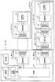
図2は、ICリーダと光ディスクに搭載された非接触型ICチップとの通信に必要な回路の構成を概略的に示す図である。
本実施の形態のICリーダ1は、主回路10、第1のアンテナ部11、第2のアンテナ部13、操作部15、通知部16、および外部通信部17を備えている。このICリーダ1は、第1のアンテナ部11を通じて直接的に、光ディスク3上の非接触型ICチップ32と通信可能であるとともに、ブースタアンテナ20を介することによって第2のアンテナ部13を通じて、光ディスクケース2に収容された状態の光ディスク3上の非接触型ICチップと通信可能である。なお、ブースタアンテナ20は、光ディスクケース2の内部に設けられて、この内部に収容された光ディスク3上の非接触型ICチップ32と、ICリーダ1の第2のアンテナコイル131などの外部のアンテナとの間で、送受信信号を中継するものである。FIG. 2 is a diagram schematically showing a circuit configuration necessary for communication between the IC reader and the non-contact type IC chip mounted on the optical disc.
The IC reader 1 according to the present embodiment includes a
ICリーダ1の主回路10は、例えば、ICリーダ1の動作を制御する制御回路、光ディスク3に設けられる非接触型ICチップ32との間で送受信する信号や電源供給用電磁波の変復調回路などから構成される。この主回路10は、光ディスク3の非接触型ICチップ32に記録されている情報を取得するための第1のアンテナ部11および第2のアンテナ部13と接続される。主回路10は、第1のアンテナ部11または第2のアンテナ部13のいずれか一方を選択的に用いて光ディスク3に搭載されている非接触型ICチップ32と通信し、非接触型ICチップ32に記録された情報を取得する。 The
第1のアンテナ部11は、光ディスクケース2に収容されていない状態の光ディスク3の非接触型ICチップ32と電磁波を送受信するためのスパイラル状の第1のアンテナコイル111、および同調回路112を有している。第2のアンテナ部13は、主に複数が並べられた光ディスクケースに収容されている状態の光ディスク3の非接触型ICチップ32と電磁波を送受信するためのスパイラル状の第2のアンテナコイル131、および同調回路132を有している。主回路10は、同調回路112を介して第1のアンテナコイル111と接続されるとともに、同調回路132を介して第2のアンテナコイル131と接続される。 The
同調回路112,132は、例えばコイル、コンデンサ、抵抗などの回路部品からなる。同調回路112内の回路部品のパラメータは、第1のアンテナコイル111と同調回路112とを含む回路が通信周波数に対するインピーダンス整合を調整するように選択される。同様に、同調回路132内の回路部品のパラメータは、第2のアンテナコイル131と同調回路132とを含む回路が通信周波数に対するインピーダンス整合を調整するように選択される。 The tuning
操作部15は、ユーザによって行われたICリーダ1への操作入力を受け付ける。通知部16は、ユーザにICリーダ1の状態を通知する。外部通信部17は、ICリーダ1と外部の情報機器との通信を行う。これらの操作部15、通知部16、および外部通信部17については、詳しくは図3において後述する。 The
光ディスク3に設けられる非接触型ICチップ32は、ICリーダ1との間で送受信する信号の変復調回路や制御回路、不揮発性記憶媒体などから構成される。ここでは一例として、非接触型ICチップ32はICリーダ1との間で電磁波を使用して通信するとともに、この非接触型ICチップ32はバッテリを持たず、ICリーダ1側から供給される電磁波から電磁誘導によって動作電力を得るものとする。また、ICリーダ1側と電磁波を送受信するためのスパイラル状のアンテナコイル31は、同調回路33を介して非接触型ICチップ32と接続される。同調回路33の機能は、ICリーダ1の同調回路112,132と同様に通信周波数に対するインピーダンス整合を調整するものである。 The non-contact
ブースタアンテナ20は、上述したように、非接触型ICチップ32側およびICリーダ1側にそれぞれ対応するスパイラル状のアンテナコイル21および22と、それらを接続する同調回路23とから構成される。同調回路23の機能は、同調回路112,132、および33と同様に通信周波数に対するインピーダンス整合を調整するものである。 As described above, the booster antenna 20 includes the spiral antenna coils 21 and 22 corresponding to the non-contact
なお、各アンテナコイル21および22のインピーダンスが通信周波数と整合している場合には特に同調回路23は不要であり、この場合にはアンテナコイル21および22を直接接続することができる。また、ICリーダ1の同調回路112,132、および非接触型ICチップ32の同調回路33も、同様に必要に応じて設けられればよい。 When the impedance of each
なお、アンテナコイル21,22,31、ならびに第1のアンテナコイル111および第2のアンテナコイル131は、スパイラル状以外に例えば1ターンのループ状アンテナを用いてもよい。 The antenna coils 21, 22, 31, and the
図3は、第1の実施の形態のICリーダの回路の構成を示す図である。
前述したように、本実施の形態のICリーダ1は、主回路10、第1のアンテナ部11、第2のアンテナ部13、操作部15、通知部16、および外部通信部17を備えている。FIG. 3 is a diagram illustrating a circuit configuration of the IC reader according to the first embodiment.
As described above, the IC reader 1 of the present embodiment includes the
主回路10は、リーダ制御部101、リーダ通信部102、およびアンテナ切替回路103を備えている。
リーダ制御部101は、このICリーダ1全体を統括的に制御する制御部である。このリーダ制御部101には、図示しないCPU(Central Processing Unit)、図示しないROMや図示しないRAM(Random Access Memory)などのメモリが備えられている。そして、このCPUが、メモリから読み出したプログラムを実行することで、ICリーダ1の各部に対する制御処理を行う。The
The
リーダ通信部102は、光ディスク3に設けられた非接触型ICチップ32との間で、非接触で通信するためのRF(Radio Frequency)回路である。リーダ通信部102は、送信データを変調する図示しない変調回路、および受信データを復調する図示しない復調回路などを備えている。 The
アンテナ切替回路103は、光ディスクに設けられた非接触型ICチップ32と通信するための第1のアンテナ部11および第2のアンテナ部13に接続されている。アンテナ切替回路103は、リーダ制御部101からの命令に応じて、第1のアンテナコイル111および同調回路112を備える第1のアンテナ部11、または、第2のアンテナコイル131および同調回路132を備える第2のアンテナ部13のうちの一方のみを選択して導通状態とする。 The
操作部15は、入力ボタン151、表示ボタン152、検索ボタン153などの各種の入力スイッチを備えており、ユーザによる操作入力に応じた制御信号をリーダ制御部101に出力する。入力ボタン151は、ユーザによる検索条件などの情報の入力を受け付けるためのボタンである。表示ボタン152は、第1のアンテナ部11を動作させることによって非接触型ICチップ32に記録された情報を取得するためのボタンである。検索ボタン153は、第2のアンテナ部13を動作させることによって非接触型ICチップ32に記録された情報を検索するためのボタンである。 The
通知部16は、表示ディスプレイ161、アンテナ発光部162、投光部163、および音声出力部164を備えており、リーダ制御部101からの指令に応じてユーザにICリーダ1の状態を通知する。表示ディスプレイ161は、第1のアンテナ部11を通じて取得された非接触型ICチップ32に記録された情報や、第2のアンテナ部13を通じて検索された結果などを表示する。アンテナ発光部162は、第1のアンテナ部11または第2のアンテナ部13によって非接触型ICチップ32と通信するときに発光する。投光部163は、たとえば、第2のアンテナ部13によって取得した情報が検索条件に該当する場合に、第2のアンテナ部13近傍から前方に向けて発光する。音声出力部164は、非接触型ICチップ32に記録された情報の検索結果などの、ICリーダ1の状態を示す音声メッセージを出力する。 The
外部通信部17は、リーダ制御部101の指令に従い、外部の情報機器との通信を行ってデータを送受信する。外部通信部17によって、IrDA(登録商標)などの赤外線通信や、Bluetooth(登録商標)などの無線通信により外部の電子機器と通信が可能である。 The
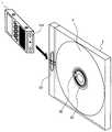
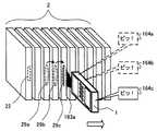
図4は、ICリーダが光ディスクケースに収容された光ディスクの非接触型ICチップと通信する際の様子を示す図である。
図4において、光ディスクケース2は、光ディスク3がその内部に装着される樹脂製の収納ケースであり、その外形は、ディスク面に対して垂直な方向が薄くされた直方体をなしている。また、ディスク面に平行な面(ケース主面)の一辺に接続する側面には、これに近接して、ICリーダ1との間で信号を受け渡すためのブースタアンテナ20(図2)を構成するアンテナコイル22が設けられている。図4の例では、光ディスクケース2のベース部に対してカバー部が回転可能に連結する連結部側の側面に、ICリーダ1と通信するためのアンテナコイル22が設けられている。また、ブースタアンテナ20を構成する他方のアンテナコイル21は、装着された光ディスク3上のアンテナコイル31に近接して対向するように、光ディスクケース2の内部に設けられている。なお、光ディスクケース2およびブースタアンテナ20の詳細な構成については後述する。FIG. 4 is a diagram showing a state in which the IC reader communicates with the non-contact type IC chip of the optical disc accommodated in the optical disc case.
In FIG. 4, an
前述したように、ICリーダ1の前面には、平板状の第2のアンテナコイル131が設けられている。ICリーダ1は、光ディスク3を収容した光ディスクケース2のブースタアンテナ20のICリーダ側のアンテナコイル22に対して、互いの長軸方向および短軸方向を一致させた状態で第2のアンテナコイル131を対向させて近接させることで、光ディスクケース2のブースタアンテナ20を介して光ディスク3の非接触型ICチップ32と通信することができる。これによって、光ディスク3の記録内容など、非接触型ICチップ32に記録された情報の検索を行うことができるようになる。 As described above, the flat plate-like
特に、このような光ディスクケース2を多数、収納棚に収容した場合には、光ディスクケース2同士はディスク面に平行な面(ケース主面)で互いに接触(または近接)するので、このケース主面にICリーダ1をかざして非接触型ICチップ32と通信させることは不可能になる。しかし、収納棚に収容した状態でも、光ディスクケース2の少なくとも1つの側面は外部に露出しているので、この側面に図4のようにブースタアンテナ20のアンテナコイル22を設けておけば、この側面にICリーダ1をかざすことで非接触型ICチップ32との通信が可能となる。 In particular, when a large number of such
そして、本実施の形態のICリーダ1によれば、収納棚に収容した状態で光ディスク3上の非接触型ICチップ32と通信することにより、例えば、非接触型ICチップ32に楽曲などの情報を記録しておき、この情報をICリーダ1で読み出して表示装置に表示することや、指定したキーワードに合致する情報が非接触型ICチップ32に記録されていたときに、音声や光などで知らせるなど、所望の楽曲やデータが収録された光ディスク3の検索を容易にすることが可能になる。 Then, according to the IC reader 1 of the present embodiment, by communicating with the non-contact
一方、ICリーダ1の他方の第1のアンテナコイル111は、光ディスク3に設けられたアンテナコイル31に対向させて近接されることで、このアンテナコイル31と電磁結合できるようにしたものである。従って、光ディスクケース2から取り出された光ディスク3、あるいは、光ディスクケース2に収容された光ディスク3に対して、そのディスク面に対向させてICリーダ1の第1のアンテナコイル111を近接させることで、光ディスク3上の非接触型ICチップ32から情報を直接読み取ることが可能である。 On the other hand, the other
なお、本実施の形態では、リモートコントローラ型のICリーダ1の例を示したが、このICリーダ1の形状や構成はあくまで一例である。ICリーダの他の構成としては、例えば、ICリーダ専用に構成されてもよく、携帯電話やその他の携帯用情報通信端末に組み込まれてもよい。 In the present embodiment, an example of the remote controller type IC reader 1 has been described. However, the shape and configuration of the IC reader 1 are merely examples. As another configuration of the IC reader, for example, it may be configured exclusively for the IC reader, or may be incorporated in a mobile phone or other portable information communication terminal.
また、本実施の形態では、ICリーダ1を非接触型ICチップからの読み取りのみ行うものとするが、これに限らず、非接触型ICチップに対する書き込みも可能なものとしてもよい。 In this embodiment, the IC reader 1 performs only reading from the non-contact type IC chip. However, the present invention is not limited to this, and writing to the non-contact type IC chip may be possible.
また、表示ディスプレイ161は、表示面に対するユーザの接触操作を検出することでリーダ制御部101に対して制御信号を出力する、いわゆるタッチパネルとして形成されてもよい。 The
図5は、非接触型ICチップが搭載された光ディスクの構成例を示す平面図である。
図5に示す光ディスク3は、CDやDVD、HD−DVD(High Definition Digital Versatile Disk)、ブルーレイディスク(Blu-ray Disc,ソニー株式会社の登録商標)などの一般的な光ディスク媒体に共通する、以下のような基本的構造を有している。すなわち、この光ディスク3には、中央部に中心孔36が設けられており、この光ディスク3がディスクドライブに挿入されたときに、この中心孔36を中心に回転され、信号記録面にレーザ光が照射されて、その反射光の光量に応じて信号が読み取られる。FIG. 5 is a plan view showing a configuration example of an optical disc on which a non-contact type IC chip is mounted.
The
光ディスク3の中心孔36から所定距離分だけ外側の領域は、銀(Ag)あるいはアルミニウム(Al)などの導電性材料からなる反射膜が成膜された信号記録領域30となっている。なお、書き込み可能な光ディスクの場合には、この信号記録領域30には反射膜の他、記録膜や誘電体膜などがさらに成膜される。 An area outside the
信号記録領域30と中心孔36との間は、ディスクドライブ内でこの光ディスク3をチャッキングするための領域であり、チャッキング領域34などと呼ばれる。そして、このチャッキング領域34には、非接触型ICチップ32と、この非接触型ICチップ32が外部のICリーダとの間で非接触で通信するためのアンテナコイル31とが設けられている。図5の例では、アンテナコイル31を3ターンのスパイラル状のものとしている。このような形状のアンテナコイル31は、例えば、通信周波数として13.56MHzに代表される短波帯を用いた場合に好適である。 The area between the
なお、非接触型ICチップ32の非接触通信のためのアンテナは、光ディスク3の回転時における重量バランスを保つために、中心孔36の周囲領域に、回転軸を中心としたスパイラル状(あるいはループ状)に設けられることが望ましい。また、このようなアンテナは、図5のようなチャッキング領域34に限らず、例えば、反射膜が成膜された領域の裏面や、その領域よりさらに外側のディスク縁部のディスク基板に設けられてもよい。ただし、チャッキング領域34およびその近傍にアンテナを配置した場合には、光ディスク3に対する加工領域を小さくできるというメリットがある。また、反射膜の成膜領域を避けてアンテナを配置することで、ディスク両面に信号を記録できることや、反射膜による電磁効果を軽減できることなどのメリットも生まれる。 Note that the antenna for non-contact communication of the non-contact
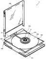
図6は、ブースタアンテナを搭載した光ディスクケースの構成例の分解斜視図である。
図6に示すように、本実施の形態の光ディスクケース2は、基本的に、外部筐体を構成するベース部231およびカバー部232と、それらの内部に収容されるディスクトレイ233とから構成される。ベース部231とカバー部232とは連結部234において回転可能な状態で連結され、ベース部231に対してカバー部232が連結部234を中心として開閉するようになっている。また、カバー部232が閉じられた状態では、カバー部232がベース部231に対して嵌合して箱形の外形が形成され、その内部が密閉される。FIG. 6 is an exploded perspective view of a configuration example of an optical disc case on which a booster antenna is mounted.
As shown in FIG. 6, the
ディスクトレイ233は、光ディスク3が装着される部材であり、ベース部231の内側に嵌着される。このディスクトレイ233には、光ディスク3が載置される円形凹状のディスク載置面235が形成され、その中心部には凸状のディスク保持部236が形成されている。ディスク保持部236の周囲は弾性を有し、このディスク保持部236に光ディスク3の中心孔36が嵌合されて、光ディスク3が保持される。 The
このようなベース部231、カバー部232、およびディスクトレイ233の3つの部材から構成される光ディスクケース2は、主にCD用の収納ケースとして最も一般的に流通されているものであり、“ジュエルケース”などと呼ばれる。なお、ベース部231、カバー部232、およびディスクトレイ233は、例えばポリスチレン樹脂材料によって形成され、一般には、少なくともベース部231およびカバー部232が透明樹脂材料により形成される。また、ベース部231およびカバー部232と、内部のディスクトレイ233とがそれぞれ別のメーカによって製造され、別々に流通される場合もある。 The
そして、本実施の形態では、この光ディスクケース2に収容された光ディスク3上の非接触型ICチップ32と通信するためのブースタアンテナ20が、ディスクトレイ233に設けられる。図7に示すように、本実施の形態において、ブースタアンテナ20は、アンテナコイル21および22が基板と一体化されたブースタアンテナユニット20aとして構成される。 In this embodiment, the booster antenna 20 for communicating with the non-contact
図7は、光ディスクケースを構成するディスクトレイおよびブースタアンテナユニットの分解斜視図である。
図7に示すように、ブースタアンテナユニット20aは、非接触型ICチップ32との通信用のアンテナコイル21と、ICリーダ1との通信用のアンテナコイル22と、各アンテナコイル21および22を接続する接続配線24とからなるブースタアンテナ20が、フレキシブル基板25の上に形成された構成をなしている。各アンテナコイル21および22、接続配線24は、例えば、アルミニウム(Al)や銅(Cu)などの金属材料をフレキシブル基板25上に印刷などによって薄板状(または薄膜状)に形成したもの、または例えば、薄板平板状の金属材料とフレキシブル基板25との貼り合せ材料から接続配線24を残すようにエッチングしたものである。FIG. 7 is an exploded perspective view of a disc tray and a booster antenna unit constituting the optical disc case.
As shown in FIG. 7, the
また、非接触型ICチップ32側のアンテナコイル21の中心領域には、フレキシブル基板25にディスクトレイ233のディスク保持部236を貫通させるための中心孔26が形成されている。さらに、この例では、フレキシブル基板25におけるアンテナコイル21および22の間の領域に、ディスクトレイ233の表面形状に合わせるための折り曲げ部27a〜27cが形成されている。 A
なお、アンテナコイル21および22のアンテナ径や巻き数などは、それぞれ非接触型ICチップ32のアンテナコイル31およびICリーダ1の第2のアンテナ部13の第2のアンテナコイル131のアンテナ径や巻き数などに応じて、良好な通信ができるように適切に決められればよい。 Note that the antenna diameter and the number of turns of the antenna coils 21 and 22 are the antenna diameter and the number of turns of the
また、このブースタアンテナユニット20aに形成されるブースタアンテナ20の回路構成は、図2に示した通りである。図7では、同調回路23が形成されていないブースタアンテナユニット20aの例を示している。同調回路23が必要な場合には、図7において、例えば、フレキシブル基板25における接続配線24が形成された領域に同調回路23が設けられればよい。前述のように同調回路23は、例えばコイル、コンデンサ、抵抗などから構成される。同調回路23の具体的な実施例としては、例えば、コンデンサ(チップコンデンサ、図示せず)の一対の電極を接続配線24の一対の配線にそれぞれ接続することで、アンテナコイル21および22に対して並列にコンデンサを接続することができる。この時、コンデンサの容量を調節することで、インピーダンスを変化させることができ、結果として通信周波数に対するインピーダンス整合を調整することができる。 The circuit configuration of the booster antenna 20 formed in the
本実施の形態の光ディスクケース2は、例えば、以下のような工程により製造される。まず、上述したように、フレキシブル基板25上に、アンテナコイル21および22と接続配線24とが印刷などにより形成されたブースタアンテナユニット20aが、平坦な状態で作製される。一方、射出成型などによりディスクトレイ233が形成される。 The
次に、ブースタアンテナユニット20aの折り曲げ部27a〜27cが、所定の方向に折り曲げ加工された後、そのブースタアンテナユニット20aが、中心孔26をディスクトレイ233のディスク保持部236に位置合わせした状態で、ディスクトレイ233の上面(ディスク載置面235側の面)に固着される。この例では、フレキシブル基板25のうち、アンテナコイル21および接続配線24の形成面の裏面が、ディスクトレイ233に対して固着される。この結果、ディスク保持部236の周囲を囲むようにアンテナコイル21が配置され、ディスク保持部236に光ディスク3が嵌合されたときに、光ディスク3側のアンテナコイル31とトレイ側のアンテナコイル21との間で確実に電磁結合し、信号を送受信できるようになる。 Next, after the
このようなブースタアンテナユニット20aがディスクトレイ233に取り付けられる一方で、ベース部231とカバー部232とが射出成型により形成されて、それらが連結部234において回転可能に連結される。そして、カバー部232を開いた状態で、ベース部231の内部に、ブースタアンテナユニット20aが固着されたディスクトレイ233が嵌め込まれて固定される。このとき、ブースタアンテナユニット20aのアンテナコイル22は、ディスクトレイ233の凸部237の端部の下部において、ベース部231の回転中心側の側面238(図6参照)の内側に密着するように配置される。 While such a
なお、ブースタアンテナユニット20aのアンテナコイル22は、基本的に、ベース部231のトレイ取り付け面の4辺にそれぞれ接続する側面のいずれかに当接(または近接)するように配設されればよい。すなわち、アンテナコイル22が当接された側面にICリーダ1をかざすことで、光ディスク3上の非接触型ICチップ32と通信できるようになる。 Note that the
ただし、上記構成の光ディスクケース2では、一般的に、カバー部232の回転中心側の側面238の内部に紙部材が配設されて、この側面238を通して光ディスク3に記録されたコンテンツのタイトルなどが表示されることが多い。このため、この光ディスクケース2を収納棚に収納した際には、側面238が収納棚の外部に露出する状態となることが多い。また、側面238の側にアンテナコイル22を配設することで、他の側面に配設した場合と比較して、光ディスク3の着脱の際にユーザがアンテナコイル22に接触してこれを破損する事態を防止できる。このような点から、アンテナコイル22は側面238に当接するように配設されることが最も好ましい。 However, in the
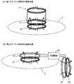
図8は、非接触型ICチップ側およびICリーダ側のアンテナ配置について説明するための図である。
光ディスク3上の非接触型ICチップ32と良好な通信を行う場合、ICリーダ1側の第1のアンテナ部11の第1のアンテナコイル111は、図8(A)に示すように光ディスク3側のアンテナコイル31と近接して対向し、かつ互いに同軸上にあることが望ましい。しかし、光ディスク3側のアンテナコイル31とICリーダ1側の第1のアンテナコイル111との位置関係が上記の状態からずれるに従って、これらの間の通信状態は悪化する。そして、図8(B)に示すように、ICリーダ1側の第1のアンテナ部11の第1のアンテナコイル111が光ディスク3の外縁のさらに外側にあり、かつ、この第1のアンテナコイル111と光ディスク3側のアンテナコイル31のそれぞれの軸が直交するような状態のときには、ほぼ通信が不可能であることが多い。FIG. 8 is a diagram for explaining antenna arrangement on the non-contact type IC chip side and the IC reader side.
When performing good communication with the non-contact
このように、各アンテナの位置関係によって良好な通信が不可能の場合でも、各アンテナの間の通信を仲介するブースタアンテナを用いることで、良好な通信が可能になる。図8(B)に示すブースタアンテナは、光ディスク3側のアンテナコイル31と対向するアンテナコイル21と、ICリーダ1側の第2のアンテナ部13の第2のアンテナコイル131と対向するアンテナコイル22とが、同調回路23を介して互いに接続されて構成される。このようなブースタアンテナを用いることで、光ディスク3側のアンテナコイル31とICリーダ1側の第2のアンテナコイル131との間の通信を確保することができる。 In this way, even when good communication is impossible due to the positional relationship between the antennas, good communication is possible by using the booster antenna that mediates communication between the antennas. The booster antenna shown in FIG. 8B includes an
図9は、光ディスクケースの別の構成例を示す正面図である。
図9の光ディスクケース50は、基本的に、表面カバー部51aと裏面カバー部51bとを備えた2つ折りの箱形形状を有している。表面カバー部51aと裏面カバー部51bとはケース側面部51cを介して折り曲げ可能に接続されており、これらは例えばポリプロピレンなどの樹脂材料によって一体に形成されている。すなわち、表面カバー部51aおよび裏面カバー部51bは、それぞれケース側面部51cとの境界部である折り曲げ部52aおよび52bにおいて90度折り曲げられ、このとき、表面カバー部51aと裏面カバー部51bとが対向する状態となって内部が密閉される。また、このときケース側面部51cは、表面カバー部51aおよび裏面カバー部51bに対して垂直な状態となって、光ディスクケース50の1つの側面を構成するようになる。FIG. 9 is a front view showing another configuration example of the optical disc case.
The
裏面カバー部51bの内面には、光ディスク3が載置されるディスク載置面53aと、光ディスク3を保持するための凸状のディスク保持部53bが一体に形成されている。前述した各実施の形態と同様に、ディスク保持部53bの周囲は弾性を有し、このディスク保持部53bに光ディスク3の中心孔36が嵌合されることで、光ディスク3が保持される。一方、表面カバー部51aの内面は、例えば光ディスク3に収録されたコンテンツを説明するための冊子などを収容するための冊子収容面54aとなっており、この面には冊子を保持し、かつ係止するための凸状の係止部54bが形成されている。 A
さらに、表面カバー部51a、裏面カバー部51b、およびケース側面部51cの外面(すなわち、ディスク載置面53aおよび冊子収容面54aの反対面)は、1枚の図示しない透明シートによって覆われている。この透明シートは、その4辺のうち3辺において、表面カバー部51a、裏面カバー部51b、およびケース側面部51cの端部と固着されているが、残る一辺は固着されずに開放されている。なお、ここでは例として、図9における上側を開放端部とする。そして、この開放端部から透明シートの内部に、例えばジャケット写真などが印刷されたパッケージ表示用のカード部材(図示せず)を挿入することが可能になっている。 Further, the outer surfaces of the
以上のような基本構成を有する光ディスクケース50は、主にDVD用の収納ケースとして最も一般的に流通されているものであり、“トールケース”などと呼ばれる。そして、本実施の形態では、このような既存の光ディスクケース50に対して、ブースタアンテナ20が形成されたブースタアンテナユニット20bが搭載される。 The
ブースタアンテナユニット20bの基本的な構成は上述した光ディスクケースの構成例と同様であり、アンテナコイル21および22と接続配線24とがフレキシブル基板25上に形成された構成となっている。このブースタアンテナユニット20bは、裏面カバー部51bの内面に、アンテナコイル21の中心領域に設けた中心孔56にディスク保持部53bを貫通させた状態で固着される。このとき、アンテナコイル22は、光ディスクケース50を閉じた状態でケース側面部51cの内面に当接するように配設される。 The basic configuration of the
ここで、ブースタアンテナユニット20bは、例えば、平坦な状態のままでそのフレキシブル基板25の裏面全体が光ディスクケース50の内面に固着される。そして、光ディスクケース50が閉じられるときには、折り曲げ部52aおよび52bが折り曲げられるのに連動して、アンテナコイル22の形成領域と接続配線24の形成領域との境界の折り曲げ部27aも折り曲げられる。この結果、ケース側面部51cの外側にICリーダ1をかざしたときに、ICリーダ1の第2のアンテナ部13の第2のアンテナコイル131とアンテナコイル22とが電磁結合されるようになる。 Here, the
また、ブースタアンテナユニット20bは、あらかじめ折り曲げ部27aを境界とした90度の折り曲げ加工が施された後、裏面カバー部51bの内面に固着されてもよい。この場合、フレキシブル基板25の裏面では、アンテナコイル21および接続配線24の形成領域のみが裏面カバー部51bに固着されればよい。 Further, the
なお、上記のトールケース型と同じ基本構成を有する光ディスクケースの例として、ケース内面に光ディスク3の載置面に隣接して、フラッシュメモリなどを備えるメモリカードを脱着可能な脱着部が設けられた光ディスクケースも存在する。このような光ディスクケースに対しても、前述した手法によってブースタアンテナを搭載させることが可能である。 As an example of an optical disk case having the same basic configuration as the above-mentioned tall case type, a detachable portion for detaching a memory card including a flash memory is provided on the inner surface of the case adjacent to the mounting surface of the
次に、第1の実施の形態のICリーダの動作について説明する。
図10は、第1の実施の形態のICリーダで実行されるメイン処理を説明するフローチャートである。Next, the operation of the IC reader according to the first embodiment will be described.
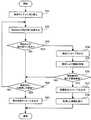
FIG. 10 is a flowchart illustrating main processing executed by the IC reader according to the first embodiment.
まず、ユーザによって操作部15が操作されると、ICリーダ1のリーダ制御部101は、ユーザによる操作部15の操作を検出する(ステップS11)。
次に、リーダ制御部101は、ステップS11でユーザによる表示ボタン152の操作を検出したか否かを判定し(ステップS12)、表示ボタン152の操作を検出していない場合には、ステップS14の処理に進む一方、表示ボタン152の操作を検出した場合には、表示通信処理を実行し(ステップS13)、その後、ステップS18の処理に進む。この表示通信処理は、光ディスク3の非接触型ICチップ32に記録されている情報を表示する処理であり、詳しくは図11において後述する。First, when the
Next, the
次に、リーダ制御部101は、ステップS11でユーザによる検索ボタン153の長押し操作(例えば、検索ボタン153を1秒以上押し続ける操作)を検出したか否かを判定し(ステップS14)、検索ボタン153の長押し操作を検出していない場合には、ステップS16の処理に進む一方、検索ボタン153の長押し操作を検出した場合には、検索通信処理を実行し(ステップS15)、その後、ステップS18の処理に進む。この検索通信処理は、光ディスク3の非接触型ICチップ32に記録されている情報の検索結果を表示する処理であり、詳しくは図12において後述する。 Next, the
次に、リーダ制御部101は、ステップS11でユーザによる検索ボタン153の二度押し操作(例えば、検索ボタン153を1秒間に2回以上押す操作)を検出したか否かを判定し(ステップS16)、検索ボタン153の二度押し操作を検出していない場合には、ステップS18の処理に進む一方、検索ボタン153の二度押し操作を検出した場合には、検索条件取得処理を実行し(ステップS17)、その後、ステップS18の処理に進む。この検索条件取得処理は、光ディスク3の非接触型ICチップ32に記録されている情報を検索する検索条件を取得する処理であり、詳しくは図13において後述する。 Next, the
そして、リーダ制御部101は、ユーザによる操作が検出されている場合には、上記の処理を繰り返し(ステップS18)、ユーザによる操作の検出が終了した場合には、処理を終了する。 Then, the
次に、メイン処理のステップS13で実行される表示通信処理について説明する。
図11は、ICリーダで実行される表示通信処理を説明するフローチャートである。
メイン処理において表示ボタン152のユーザによる操作が検出されると、リーダ制御部101によって図11に示す表示通信処理が実行される。Next, the display communication process executed in step S13 of the main process will be described.
FIG. 11 is a flowchart for explaining display communication processing executed by the IC reader.
When the operation of the
まず、リーダ制御部101は、アンテナ切替回路103に対して、接続先を第1のアンテナ部11に切り替える指令を送信し(ステップS21)、接続された第1のアンテナ部11によって、光ディスク3の非接触型ICチップ32の検出および記録されている情報の読み取りを試みる(ステップS22)。そして、リーダ制御部101は、この非接触型ICチップ32の検出および読み取りに成功したか否かを判定し(ステップS23)、検出および読み取りに失敗した場合には、ステップS27の処理に進む一方、検出および読み取りに成功した場合には、ステップS24の処理に進む。 First, the
非接触型ICチップ32の検出および読み取りに成功した場合、リーダ制御部101は、非接触型ICチップ32の検出および記録されている情報の読み取りに成功したことを示す検出メッセージを通知部16に出力させ(ステップS24)、非接触型ICチップ32との通信によって非接触型ICチップ32に記録されている必要な情報を取得し(ステップS25)、取得した情報を通知部16に設けられた表示ディスプレイ161に表示させ(ステップS26)、その後、メイン処理に復帰する。 When the detection and reading of the non-contact
非接触型ICチップ32の検出または読み取りに失敗した場合、リーダ制御部101は、ステップS22からステップS23の処理を予め定められた規定回数(例えば、10回)だけ繰り返す。そして、リーダ制御部101は、この繰り返しが規定回数を超えたか否かを判定し(ステップS27)、繰り返しが規定回数を超えていない場合には、ステップS22の処理に進む一方、繰り返しが規定回数を超えた場合には、非接触型ICチップの検出または記録されている情報の読み取りに失敗したことを示す検出失敗メッセージを通知部16に出力させ、その後、メイン処理に復帰する。 When the detection or reading of the non-contact
ここで、検出メッセージおよび検出失敗メッセージは、例えば、音声出力部164に所定の電子音や、合成音によるメッセージを出力させてもよい。また、アンテナ発光部162や投光部163による所定の発光パターンで、ユーザに対して非接触型ICチップの検出または読み取りの成功または失敗を通知してもよい。 Here, as the detection message and the detection failure message, for example, the
なお、上記のステップS26では、非接触型ICチップ32から取得した情報をそのまま表示ディスプレイ161に表示する他に、例えば、取得した情報にあらかじめ対応付けられていた情報を表示してもよい。例えば、識別番号と楽曲名とを対応付けたテーブルをあらかじめ保持しておき、非接触型ICチップ32から識別番号を取得すると、テーブルを参照して対応する楽曲名を抽出し、表示ディスプレイ161に表示してもよい。 In step S26 described above, in addition to displaying the information acquired from the non-contact
次に、メイン処理のステップS15で実行される検索通信処理について説明する。
図12は、第1の実施の形態のICリーダで実行される検索通信処理を説明するフローチャートである。Next, the search communication process executed in step S15 of the main process will be described.
FIG. 12 is a flowchart illustrating search communication processing executed by the IC reader according to the first embodiment.
メイン処理において検索ボタン153のユーザによる長押し操作が検出されると、リーダ制御部101によって図12に示す検索通信処理が実行される。
まず、リーダ制御部101は、アンテナ切替回路103に対して、接続先を第2のアンテナ部13に切り替える指令を送信し(ステップS31)、接続された第2のアンテナ部13によって、光ディスク3の非接触型ICチップ32の検出および記録されている情報の読み取りを試みる(ステップS32)。そして、リーダ制御部101は、この非接触型ICチップ32の検出および読み取りに成功したか否かを判定し(ステップS33)、検出および読み取りに失敗した場合には、ステップS39の処理に進む一方、検出および読み取りに成功した場合には、ステップS34の処理に進む。When a long press operation by the user of the
First, the
非接触型ICチップ32の検出および読み取りに成功した場合、リーダ制御部101は、非接触型ICチップ32の検出および記録されている情報の読み取りに成功したことを示す検出メッセージを通知部16に出力させ(ステップS34)、非接触型ICチップ32との通信によって非接触型ICチップ32に記録されている必要な情報を取得する(ステップS35)。 When the detection and reading of the non-contact
次に、リーダ制御部101は、取得した情報を、図13の検索条件取得処理によって取得した検索条件によって検索して、検索条件に該当する情報を発見したか否かを判定する(ステップS36)。検索条件に該当する情報を発見しない場合、リーダ制御部101は、ステップS39に処理を進める一方、検索条件に該当する情報を発見した場合、非接触型ICチップ32に検索条件に該当する情報が記録されていることを示す検索該当メッセージを通知部16に出力させ(ステップS37)、取得した情報を通知部16に設けられた表示ディスプレイ161に表示させ(ステップS38)、その後、メイン処理に復帰する。 Next, the
ステップS33において非接触型ICチップ32の検出もしくは読み取りに失敗した場合、またはステップS36において非接触型ICチップ32から検索条件に該当する情報を発見しなかった場合、リーダ制御部101は、ユーザによる検索ボタン153の長押しが解除されたか否かを判定し(ステップS39)、長押しが解除されていない場合には、ステップS32の処理に進む。これにより、ユーザにより検索ボタン153が長押しされている間、ステップS32からステップS36の処理が繰り返される。一方、長押しが解除されている場合には、非接触型ICチップの検出または記録されている情報の読み取りに失敗したことを示す検出失敗メッセージを通知部16に出力させ(ステップS40)、その後、メイン処理に復帰する。 If the detection or reading of the non-contact
ここで、検出メッセージ、検出失敗メッセージ、および検索該当メッセージは、表示通信処理(図11)のステップS24の検出メッセージなどと同様に、例えば、音声出力部164に所定の電子音や、合成音によるメッセージを出力させてもよい。また、アンテナ発光部162や投光部163による所定の発光パターンで、ユーザに対して非接触型ICチップの検出および読み取りの成功もしくは失敗、または検索条件に該当する情報の発見を通知してもよい。 Here, the detection message, the detection failure message, and the search relevant message are generated by, for example, a predetermined electronic sound or synthesized sound in the
次に、メイン処理のステップS17で実行される検索条件取得処理について説明する。
図13は、ICリーダで実行される検索条件取得処理を説明するフローチャートである。Next, the search condition acquisition process executed in step S17 of the main process will be described.
FIG. 13 is a flowchart for explaining search condition acquisition processing executed by the IC reader.
メイン処理において検索ボタン153のユーザによる二度押し操作が検出されると、リーダ制御部101によって図13に示す検索条件取得処理が実行される。
まず、リーダ制御部101は、アンテナ切替回路103に対して、接続先を第2のアンテナ部13に切り替える指令を送信する(ステップS41)。なお、この検索条件取得処理では、第2のアンテナ部13ではなく、第1のアンテナ部11に切り替えて、検索条件を第1のアンテナ部11を通じて取得するようにしてもよい。When a double pressing operation by the user of the
First, the
次に、ユーザによって操作部15が操作されると、リーダ制御部101は、ユーザによる操作部15の操作を検出する(ステップS42)。
次に、リーダ制御部101は、ステップS42でユーザによる入力ボタン151の操作を検出したか否かを判定し(ステップS43)、入力ボタン151の操作を検出していない場合には、接続された第2のアンテナ部13によって、光ディスク3の非接触型ICチップ32の検出および記録されている情報の読み取りを試み(ステップS46)、ステップS47の処理に進む一方、入力ボタン151の操作を検出した場合には、ユーザによる入力ボタン151の操作を検出することによって検索条件の入力を受け付けて検索条件を取得し(ステップS44)、取得した検索条件をリーダ制御部101内のRAMに記憶し(ステップS45)、ステップS51の処理に進む。Next, when the
Next, the
次に、ステップS47では、リーダ制御部101は、ステップS46における非接触型ICチップ32の検出および読み取りに成功したか否かを判定し(ステップS47)、検出および読み取りに失敗した場合には、ステップS50の処理に進む一方、検出および読み取りに成功した場合には、第2のアンテナ部13を通じて非接触型ICチップ32に記憶されている情報から検索条件を取得し(ステップS48)、取得した検索条件をリーダ制御部101内のRAMに記憶し(ステップS49)、ステップS51の処理に進む。 Next, in step S47, the
次に、ステップS51では、検索条件の取得に成功したことを示す検索条件取得メッセージを通知部16に出力させ(ステップS51)、その後、メイン処理に復帰する。
ステップS47において検出および読み取りに失敗した場合、リーダ制御部101は、ステップS42からステップS47の処理を予め定められた規定回数(例えば、10回)だけ繰り返す。そして、リーダ制御部101は、この繰り返しが規定回数を超えたか否かを判定し(ステップS50)、繰り返しが規定回数を超えていない場合には、ステップS42の処理に進む一方、繰り返しが規定回数を超えた場合には、検索条件の取得に失敗したことを示す検索条件取得失敗メッセージを通知部16に出力させ、その後、メイン処理に復帰する。Next, in step S51, a search condition acquisition message indicating that acquisition of the search condition is successful is output to the notification unit 16 (step S51), and then the process returns to the main process.
If detection and reading fail in step S47, the
ここで、検索条件取得メッセージおよび検索条件取得失敗メッセージは、表示通信処理(図11)のステップS24の検出メッセージなどと同様に、例えば、音声出力部164に所定の電子音や、合成音によるメッセージを出力させてもよい。また、アンテナ発光部162や投光部163による所定の発光パターンで、検索条件の取得または取得の失敗を通知してもよい。 Here, the search condition acquisition message and the search condition acquisition failure message are, for example, a message by a predetermined electronic sound or synthesized sound in the
次に、本実施の形態のICリーダによる光ディスクに搭載された非接触型ICチップに記憶されている情報の検索時の様子について説明する。
まず、ICリーダによって、前述した光ディスクケースに収容されている光ディスクの非接触型ICチップを検出する際の様子を説明する。Next, a description will be given of a state when searching for information stored in a non-contact type IC chip mounted on an optical disc by the IC reader of the present embodiment.
First, a state when an IC reader detects a non-contact type IC chip of an optical disc accommodated in the above-described optical disc case will be described.
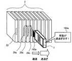
図14は、ICリーダで光ディスクケースに収容された非接触型ICチップが搭載された光ディスクを検出する際の様子を示す図である。
例えば、従来、図14のように非接触型ICチップを搭載した光ディスクを収容する光ディスクケースが、立てられた状態で横に多数並べられているような場合に、光ディスクの非接触型ICチップに記録されている情報を読み取るときには、通信を成立させるために、光ディスクケースを一々手に取って、または収容されている光ディスクを取り出して、光ディスクのディスク面に配置された非接触型ICチップのアンテナコイルをICリーダにかざさなければならなかった。FIG. 14 is a diagram showing a state in which an optical disk loaded with a non-contact type IC chip housed in an optical disk case is detected by an IC reader.
For example, as shown in FIG. 14, when a large number of optical disk cases for storing optical disks mounted with a non-contact IC chip are arranged side by side in a standing state, the non-contact IC chip of the optical disk is used. When reading recorded information, in order to establish communication, the antenna of the non-contact type IC chip disposed on the disk surface of the optical disk by picking up the optical disk case one by one or taking out the stored optical disk The coil had to be held over the IC reader.
これに対して、前述したブースタアンテナ20を搭載した光ディスクケース2を上記と同様に多数並べた場合には、これらの光ディスクケース2の側面に配設された、ブースタアンテナ20のアンテナコイル22に対して、ICリーダ1の前面の第2のアンテナコイル131を順次近接させていくことで、光ディスク3の非接触型ICチップ32から記録されている情報を読み取っていくことができる。従って、光ディスク3や光ディスクケース2に手を触れることなく、非接触型ICチップ32に記録されている情報を読み取ることができる。 On the other hand, when a large number of
以下に、本実施の形態のICリーダ1を、前述した光ディスク3および光ディスクケース2と組み合わせて、非接触型ICチップ32に記録されている情報の検索に用いた場合の様子について説明する。 Hereinafter, a state in which the IC reader 1 of the present embodiment is used for searching for information recorded on the non-contact
光ディスクケース2には、それぞれ前述したブースタアンテナユニットが備えられており、光ディスクケース2の側面側(図14の手前側)には、ブースタアンテナユニットのICリーダ側のアンテナコイル22が設けられている。 Each
図12において説明したように、ユーザがICリーダ1の検索ボタン153を長押ししながら前面に設けられた第2のアンテナ部13を、それぞれの光ディスクケース2のアンテナコイル22に対して(図14の例では左から右に)順次かざしていくことによって、それぞれの光ディスク3に搭載された非接触型ICチップ32に記録された情報を読み取ることができる。このとき、ICリーダ1の通知部16から、光ディスクの非接触型ICチップ32を検出し、通信に成功した旨を通知する検出メッセージが出力される。検出メッセージは、具体的には、ICリーダ1の投光部163から照射される照射光163aや、音声出力部から出力される音声メッセージ164a〜164cなどである。 As described with reference to FIG. 12, the user holds down the
ICリーダ1は、照射光163aの特定の発光パターン(例えば、ICリーダ1が非接触型ICチップ32を検出し、通信に成功する都度発光して照射光163aを出力)や、音声メッセージ164a〜164cの特定の音(例えば、ICリーダ1が非接触型ICチップ32を検出し、通信に成功する都度「ピッ!」という電子音)などを出力する。これらによって、ユーザに非接触型ICチップ32の検出および通信の成功を通知することができる。また、このとき照射光163aは、ICリーダ1の検出対象の光ディスクケース2に向けて投光されるので、ユーザにICリーダ1が現在どの光ディスクケース2と通信を試みているかを簡単に認識させることができる。 The IC reader 1 uses a specific light emission pattern of the
また、光ディスクケース2の構造や配置などによって、光ディスクケース2の外から内部の光ディスクの有無を視認し難い場合であっても、ユーザに通知部16による検出メッセージによって、当該光ディスクケース2の内部に非接触型ICチップ32を搭載した光ディスク3が収容されていることを通知することができる。 Even if it is difficult to visually recognize the presence or absence of an internal optical disk from the outside of the
このとき、光ディスクケース2に、非接触型ICチップ32を搭載した光ディスク3が収容されていなければ、検出メッセージは出力されない。これにより、ユーザに当該光ディスクケース2は空であるか、当該光ディスクケースに収容されている光ディスクは非接触型ICチップ32を搭載していないかのいずれかであることを認識させることができる。 At this time, if the
なお、ICリーダ1の検出メッセージを出力する投光部163を、紫外線を発光する紫外線LEDなどで構成するとともに、光ディスクケース2の背面側のアンテナコイル22が配置されている部分に、ルミノーバ(登録商標)などの、紫外線の照射を受けると蓄光する蓄光塗料を塗布しておいてもよい。これにより、ICリーダ1の投光部163から検出メッセージとして出力される紫外線の照射光163aを受光すると、図14の受光部分29a〜29cのように、しばらくの間発光し続けるので、ユーザに、ICリーダ1によって検出され、通信に成功した非接触型ICチップ32を搭載した光ディスクが収容されている光ディスクケース2を、より明確に認識させることができる。 The
そして、図12の検索通信処理の実行時において、非接触型ICチップ32の検出および通信に成功したICリーダ1は、その非接触型ICチップ32に記憶されている情報について検索を行う。 Then, when the search communication process of FIG. 12 is executed, the IC reader 1 that has successfully detected and communicated with the non-contact
なお、光ディスクケース2が、横に寝かされて縦に積み上げられているような場合には、ユーザは、ICリーダ1を、前後方向を軸にして右または左に90度回転させた状態で用いることにより、同様の効果を発揮させることができる。 When the
次に、ICリーダによって、前述した光ディスクの非接触型ICチップに記憶されている情報について検索する際の様子を説明する。
図15は、光ディスクケースに収容された光ディスクの非接触型ICチップに記録された情報の検索に成功した際の様子を示す図である。Next, a description will be given of how the IC reader searches for information stored in the non-contact type IC chip of the optical disc described above.
FIG. 15 is a diagram showing a state when the information recorded on the non-contact type IC chip of the optical disk accommodated in the optical disk case is successfully retrieved.
ICリーダ1は、図14において前述したように、検索時において光ディスクケース2に収容された光ディスク3に搭載された非接触型ICチップ32の検出および通信に成功すると、非接触型ICチップ32に記憶されている情報に対して、検索条件に該当する情報があるか否かについて検索を行う。 As described above with reference to FIG. 14, when the IC reader 1 succeeds in detecting and communicating with the non-contact
そして、この検索の結果、非接触型ICチップ32に記憶されている検索条件に該当する情報がない場合には、ICリーダ1から音声メッセージ164a,164bや照射光163aなどの前述した検出メッセージが出力されるのみであり、当該非接触型ICチップ32の検索の実行に応じては、ICリーダ1の通知部16から検索に関するメッセージは出力されない。 If there is no information corresponding to the search condition stored in the non-contact
一方、検索の結果、非接触型ICチップ32に記憶されている検索条件に該当する情報がある場合には、ICリーダ1の通知部16から、検出メッセージと異なり、ユーザに検索に成功したことを通知する検索成功メッセージが出力される。検索成功メッセージは、具体的には、ICリーダ1の投光部163から照射される、照射光163aとは異なるパターンの照射光163bや、音声出力部から出力される音声メッセージ164a〜164cとは異なる音声メッセージ164dなどである。 On the other hand, if there is information corresponding to the search condition stored in the non-contact
このように、ICリーダ1は、検出メッセージとは異なる照射光163aの特定の発光パターン(例えば、ICリーダ1が非接触型ICチップ32に記憶されている情報の検索に成功した場合に、検出メッセージと異なる色で発光する別の発光部が発光して照射光163bを出力)や、音声メッセージ164a〜164cとは異なる特定の音声メッセージ164d(例えば、ICリーダ1が非接触型ICチップ32に記憶されている情報から「運動会」というキーワードを含む情報の検索に成功した場合に、「運動会のディスクを見つけました」という合成音声)などによって、ユーザに非接触型ICチップ32に記憶されている情報の検索の成功を通知することができる。 As described above, the IC reader 1 detects the specific light emission pattern of the
これにより、ユーザは、複数並べられた光ディスクケース2に触れることなく、検索条件に従って、光ディスク3が搭載している非接触型ICチップ32に記録されている情報を検索することができるとともに、検索結果を容易に認識することができる。 Thereby, the user can search the information recorded on the non-contact
なお、ICリーダ1の投光部163の照射光163aによる発光パターンの他の例として、まず常時発光させておき、非接触型ICチップ32の検出および通信の成功時に所定の発光パターン(例えば、長い周期の点滅)で投光し、さらに非接触型ICチップ32に記憶されている情報の検索の成功時にさらに異なる発光パターン(例えば、短い周期の点滅)で投光するようにしてもよい。 As another example of the light emission pattern by the
また、検出メッセージと同様に、検索成功メッセージを出力するICリーダ1の投光部163を、紫外線を発光する紫外線LEDなどで構成するとともに、光ディスクケース2の背面側のアンテナコイル22が配置されている部分に、ルミノーバ(登録商標)などの、紫外線の照射を受けると蓄光する蓄光塗料を塗布しておいてもよい。これにより、ICリーダ1の投光部163から検索成功メッセージとして出力される紫外線の照射光163bを受光すると、図15の受光部分29dのように、照射光163bが照射されなくなっても、しばらくの間発光し続けるので、ユーザに、ICリーダ1による情報の検索に成功した非接触型ICチップ32を搭載した光ディスク3が収容されている光ディスクケース2を、より明確に認識させることができる。 Similarly to the detection message, the
次に、光ディスクに搭載された非接触型ICチップに記録されている情報について説明する。
図16〜図19は、非接触型ICチップに記録されているディスク主情報およびディスク補助情報を示す図である。Next, information recorded on the non-contact type IC chip mounted on the optical disc will be described.
16 to 19 are diagrams showing disk main information and disk auxiliary information recorded in the non-contact type IC chip.
本実施の形態のICリーダ1は、ユーザが、動画ファイル、データファイル、プログラムファイル、音楽ファイルなどの、光ディスク3に記録されている内容の検索を行うために、非接触型ICチップ32に記録されている情報から検索条件に該当する情報の有無を判定する機能を備えている。ここで、ICリーダ1による検索に用いられる、非接触型ICチップ32に記録される情報について説明する。 The IC reader 1 according to the present embodiment is recorded on the non-contact
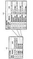
光ディスク3の非接触型ICチップ32に記録されている情報は、図16〜図19に示すように、ディスク主情報411〜414と、ディスク補助情報421〜424とにより構成されている。 Information recorded on the non-contact
ディスク主情報411〜414は、例えば、図16に示すように、「要素番号」、「情報種別」、および「内容」の3つの情報から構成され、横方向に並べられた情報同士が互いに関連付けられて、非接触型ICチップ32に格納されているディスク主情報テーブルに格納されている。 For example, as shown in FIG. 16, the disk
要素番号は、ディスク主情報テーブルに格納されている各ディスク主情報を識別するために割り当てられた番号である。要素番号は、関連付けられた各ディスク主情報に対して、各非接触型ICチップ32内でユニークに割り当てられる。 The element number is a number assigned to identify each piece of disk main information stored in the disk main information table. The element number is uniquely assigned in each non-contact
情報種別は、そのディスク主情報がどのような種類の情報であるかを示す情報である。情報種別には、例えば、その非接触型ICチップ32を識別するための記号である「チップID」、その非接触型ICチップ32を搭載している光ディスクを識別するための記号である「ディスクID」、そのディスク主情報が、テレビ番組を録画した動画データに対応付けられているものであることを示す「TV番組」、そのディスク主情報が、音楽曲を録音した音楽データに対応付けられているものであることを示す「音楽曲」などがある。なお、情報種別の種類は、これに限られず、必要に応じて定めることができる。 The information type is information indicating what type of information the disk main information is. The information type includes, for example, a “chip ID” that is a symbol for identifying the non-contact
内容は、そのディスク主情報が示す情報である。この内容は、情報種別に応じたものが格納される。例えば、情報種別が「ディスクID」や「チップID」の場合には、それぞれディスクIDまたはチップIDを示す記号が格納される。情報種別が「TV番組」や「音楽曲」の場合には、それぞれテレビ番組または音楽曲のタイトルが格納される。 The contents are information indicated by the disc main information. This content is stored according to the information type. For example, when the information type is “disk ID” or “chip ID”, a symbol indicating the disk ID or chip ID is stored. When the information type is “TV program” or “music song”, the title of the TV program or music song is stored.
ディスク補助情報421〜424は、例えば、図16に示すように、「要素番号」、「主情報番号」、「情報種別」、および「内容」の4つの情報から構成され、横方向に並べられた情報同士が互いに関連付けられて、非接触型ICチップ32に格納されているディスク主情報テーブルに格納されている。ディスク補助情報421〜424は、光ディスク3に記録されている内容の検索に用いるための情報であり、本実施の形態では、ディスク主情報の前述したTV番組および音楽曲に従属して設けられている。 For example, as shown in FIG. 16, the disk
要素番号は、ディスク補助情報テーブルに格納されている各ディスク補助情報を識別するために割り当てられた番号である。要素番号は、関連付けられた各ディスク補助情報に対して、各非接触型ICチップ32内でユニークに割り当てられる。主情報番号は、そのディスク補助情報が従属しているディスク主情報を特定するための番号である。主番号情報は、ディスク主情報の要素番号が用いられる。この主情報番号によって、1つのディスク主情報に対して1つ以上のディスク補助情報が対応付けられる。 The element number is a number assigned to identify each piece of disk auxiliary information stored in the disk auxiliary information table. The element number is uniquely assigned in each non-contact
情報種別は、そのディスク補助情報がどのような種類の情報であるかを示す情報である。情報種別には、例えば、そのディスク補助情報がテレビ番組に関するものである場合には、「番組録画時間」、「番組副タイトル」、「番組種別」、「番組出演者」などがあり、そのディスク補助情報が音楽曲に関するものである場合には、「音楽演奏時間」、「音楽歌手」、「音楽作詞作曲」などがある。なお、情報種別の種類は、これに限られず、必要に応じて定めることができる。 The information type is information indicating what type of information the disk auxiliary information is. The information type includes, for example, “program recording time”, “program subtitle”, “program type”, “program performer”, etc., when the disc auxiliary information is related to a television program. When the auxiliary information relates to a music song, there are “music performance time”, “music singer”, “music songwriting”, and the like. The type of information type is not limited to this, and can be determined as necessary.
内容は、そのディスク補助情報が示す情報である。この内容は、情報種別に応じたものが格納される。例えば、情報種別が「番組録画時間」の場合には、テレビ番組の録画開始時間および録画終了時間が格納される。情報種別が「番組副タイトル」の場合には、テレビ番組の副タイトルが格納される。情報種別が「番組種別」の場合には、「ニュース」や「スポーツ」などのテレビ番組の種別が格納される。情報種別が「番組出演者」の場合には、テレビ番組の出演者名が格納される。情報種別が「音楽演奏時間」の場合には、音楽曲の演奏の録音時間が格納される。情報種別が「音楽歌手」の場合には、音楽曲の歌手名が格納される。情報種別が「音楽作詞作曲」の場合には、音楽曲の作詞者名および作曲者名が格納される。 The contents are information indicated by the disk auxiliary information. This content is stored according to the information type. For example, when the information type is “program recording time”, the recording start time and recording end time of the television program are stored. When the information type is “program subtitle”, the subtitle of the television program is stored. When the information type is “program type”, the type of TV program such as “news” or “sports” is stored. When the information type is “program performer”, the name of the performer of the television program is stored. When the information type is “music performance time”, the recording time of the performance of the music tune is stored. When the information type is “music singer”, the singer name of the music song is stored. When the information type is “music songwriting”, the songwriter name and the composer name of the music song are stored.
本実施の形態のICリーダ1は、光ディスク3の非接触型ICチップ32に記録されているこれらのディスク主情報およびディスク補助情報に基づいて、光ディスク3に記録されている内容を検索することができる。 The IC reader 1 of the present embodiment can search the content recorded on the
次に、本実施の形態のICリーダ1で行われる検索および検索時にICリーダ1の表示ディスプレイ161に表示される検索表示画面について説明する。
図20〜図25は、表示ディスプレイに表示される検索表示画面を示す図である。Next, a search performed on the IC reader 1 of the present embodiment and a search display screen displayed on the
20 to 25 are diagrams showing search display screens displayed on the display.
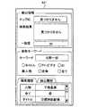
検索表示画面431〜436は、大別すると、「検出情報欄」、「検索キーワード欄」、および「履歴欄」から構成されている。
検出情報欄は、「チップID欄」、「検索結果欄」、および「一致度表示欄」から構成されている。The search display screens 431 to 436 are roughly divided into a “detection information column”, a “search keyword column”, and a “history column”.
The detection information column includes a “chip ID column”, a “search result column”, and a “matching degree display column”.
チップID欄は、ICリーダ1が非接触型ICチップ32を検出した場合に、その非接触型ICチップ32と通信して取得したディスク主情報(図16〜図19参照)のチップIDが表示される欄である。 In the chip ID column, when the IC reader 1 detects the non-contact
検索結果欄は、ICリーダ1が検索条件に基づき非接触型ICチップ32に記録されている情報を検索した結果、検索条件に該当する情報を発見した場合に、その発見された情報および発見された情報に関連する情報が表示される欄である。 In the search result column, when the IC reader 1 searches the information recorded in the non-contact
一致度表示欄は、ICリーダ1が検索条件に基づき非接触型ICチップ32に記録されている情報を検索して検索条件に該当した情報について、検索キーワードに基づく検索結果の一致の程度を評価した値である一致度を表示する欄である。この一致度は、例えば、検索条件に該当した情報の、検索対象のディスク主情報およびディスク補助情報の項目数に対する、検索キーワードと一致した項目数の比によって算出するが、これに限らず、他の尺度を用いることができる。 In the match level display column, the IC reader 1 searches the information recorded in the non-contact
検索キーワード欄は、「キーワード欄」および「検索項目選択ボタン」から構成されている。キーワード欄は、検索条件を構成するキーワードを入力する欄である。検索項目選択ボタンは、検索条件を構成する検索対象の指定を入力する選択ボタンである。 The search keyword field is composed of a “keyword field” and a “search item selection button”. The keyword column is a column for inputting keywords constituting the search condition. The search item selection button is a selection button for inputting designation of a search target constituting a search condition.
なお、検索条件は、外部通信部17を通じて、例えば携帯電話などの外部の情報端末装置から取得してもよい。
履歴欄は、「検索履歴タブ」および「検出履歴タブ」を備えている。
検索履歴タブを選択すると、過去に検索したキーワードが表示される。検出履歴タブを選択すると、過去に検出された情報が表示される。これらの検索履歴タブおよび検出履歴タブによって表示された語句を選択してコピーすることによって、検索のためのキーワードとして用いることができる。The search condition may be acquired from an external information terminal device such as a mobile phone through the
The history column includes a “search history tab” and a “detection history tab”.
When the search history tab is selected, keywords searched in the past are displayed. When the detection history tab is selected, information detected in the past is displayed. By selecting and copying the words displayed by these search history tab and detection history tab, they can be used as keywords for search.
図20は、キーワードを「北野一郎」として「人物」について検索するように設定されている場合であって、光ディスク3が検出できない状態における検索表示画面431を示している。ここで例えば、「人物」について検索するように設定した場合、図16〜図19で示した非接触型ICチップに記録されているディスク主情報411〜414およびディスク補助情報421〜424の中から、情報種別として「番組出演者」「音楽歌手」「音楽作詞作曲」などの人物に関する情報として格納されている中から、キーワード検索をするように設定したことに相当する。 FIG. 20 shows a
図21は、キーワードを「北野一郎」として「人物」について検索するように設定されている場合であって、チップIDが「9E8F2D64AC35B702」である光ディスク3(図17参照)を検出したが、検索条件に該当する情報を発見できなかった状態における検索表示画面432を示している。すなわち、図17で例示した情報の格納状態に対して、情報種別として「番組出演者」「音楽歌手」「音楽作詞作曲」などの人物に関する情報の中に、「北野一郎」が格納されていなかったことに相当する。 FIG. 21 shows a case where the keyword “Ichiro Kitano” is set to search for “person”, and the optical disk 3 (see FIG. 17) whose chip ID is “9E8F2D64AC35B702” is detected. The
図22は、キーワードを「北野一郎」として「人物」について検索するように設定されている場合であって、チップIDが「9E8F2D64AC35B701」である光ディスク3(図16参照)を検出し、検索条件に該当する情報を発見した状態における検索表示画面433を示している。すなわち、図16で例示した情報の格納状態に対して、ディスク補助情報421の中の情報種別として「番組出演者」である要素番号B3に検索条件に該当する情報を発見し、ディスク主情報411の中の要素番号A3の「TV番組」「おはよう朝です」が検索結果であることを表示している。 FIG. 22 shows a case where the search is performed for “person” with the keyword “Ichiro Kitano”, and the optical disk 3 (see FIG. 16) whose chip ID is “9E8F2D64AC35B701” is detected, and the search condition is set. A
図23は、キーワードを「北野一郎」として「人物」について検索するように設定されている場合であって、チップIDが「9E8F2D64AC35B703」である光ディスク3(図18参照)を検出し、検索条件に該当する情報を発見した状態における検索表示画面434を示している。この場合、図18で例示した情報の格納状態に対して、ディスク補助情報423の中の情報種別として「番組出演者」である要素番号B3に検索条件に類似した「北野二郎」という情報(「北野一郎」と1文字違いの情報)を発見し、検索結果の一致度が「25%」という低い状態ではあるものの、ディスク主情報413の中の要素番号A3の「TV番組」「野球中継」が類似した検索結果であることを表示している。 FIG. 23 shows a case where the keyword is set to search for “person” with “Ichiro Kitano” as the keyword, and the optical disk 3 (see FIG. 18) whose chip ID is “9E8F2D64AC35B703” is detected and the search condition is set. A
図24は、キーワードを「空上健一」として「全て」について検索するように設定されている場合であって、チップIDが「9E8F2D64AC35B702」である光ディスク3(図17参照)を検出し、検索条件に該当する情報を発見した状態における検索表示画面435を示している。この場合、図17で例示した情報の格納状態に対して、情報種別として全てに検索を行った結果、ディスク補助情報422の中の要素番号B9に検索条件に該当する情報を発見し、ディスク主情報412の中の要素番号A5の「音楽曲」「明日は天気」の中の作曲者として一致度が低い状態で検索結果に該当したことを表示している。 FIG. 24 shows a case where “all” is set as the keyword “Kenichi Sorakami”, and the optical disk 3 (see FIG. 17) whose chip ID is “9E8F2D64AC35B702” is detected and the search condition is set. The
図25は、キーワードを「空上健一」として「全て」について検索するように設定されている場合であって、チップIDが「9E8F2D64AC35B704」である光ディスク3(図19参照)を検出し、検索条件に該当する情報を発見した状態における検索表示画面436を示している。すなわち、図18で例示した情報の格納状態に対して、情報種別として全てに検索を行った結果、ディスク補助情報424の中の要素番号B2、B3、B5、B6、B8、B9に検索条件に該当する情報を発見し、ディスク主情報414の中の要素番号A3、A4、A5の3つの「音楽曲」が検索結果であることを表示している。 FIG. 25 shows a case where “all” is set as the keyword “Kenichi Sorakami”, and the optical disk 3 (see FIG. 19) whose chip ID is “9E8F2D64AC35B704” is detected and the search condition is set. A
以上説明した第1の実施の形態のICリーダ1によれば、非接触型ICチップ32と光ディスク3の回転中心を中心として形成された非接触通信用のアンテナコイル31とが設けられた光ディスク3を内部に収容する光ディスクケース2であって、光ディスクの非接触型ICチップ32との通信を補助するブースタアンテナ20を側面に備える光ディスクケース2に対し、その光ディスクケース2を閉じた状態で、情報読み取り装置の第2のアンテナを、ブースタアンテナ20が設けられているケース側面に近接させることで、ICリーダ1と光ディスク3上の非接触型ICチップ32との間で確実に通信できるようになる。 According to the IC reader 1 of the first embodiment described above, the
この結果、非接触型ICチップ32が設けられた光ディスク3について、光ディスクケース2に収納された光ディスク3が並べられた状態、ならびに、光ディスク3を収納した光ディスクケース2単体、および光ディスクケース2に収納されていない光ディスク3単体の状態のいずれの状態でも、光ディスク3の非接触型ICチップ32と容易に通信でき、光ディスク3の記録内容などの、非接触型ICチップ32に記録されている情報を容易に把握することが可能になる。 As a result, for the
さらに、第2のアンテナで非接触型ICチップ32から情報を取得する場合には、非接触型ICチップ32からの、検索条件に該当する情報の検索が可能になる。これにより、例えば、光ディスクケース2が多数並べられている場合でも、その状態のままで、所望のデータを記憶した光ディスク3が収容されている光ディスクケース2を簡単に探し出すことができる。 Furthermore, when information is acquired from the non-contact
[第2の実施の形態]
次に、第2の実施の形態について説明する。横に複数並べられた光ディスクケース2に収納された光ディスク3の非接触型ICチップ32の記録内容を、ICリーダによって検索する際、移動速度が速過ぎる場合には、読み取りエラーが発生したり、非接触型ICチップ32の読み飛ばしが発生したりする可能性がある。このため、第2の実施の形態のICリーダ7は、ICリーダ7自身の移動速度を検出する移動速度検出部78によって検索中の移動速度を検出する。そして、本実施の形態のICリーダ7は、検出された移動速度が所定の範囲内であれば、速度が適正であることを通知し、検出された移動速度が速過ぎるなど、所定の範囲外である場合には、ユーザに対して移動速度が異常であることを通知する点で第1の実施の形態と異なる。なお、他の構成要素については同一符号としており、説明を省略する。[Second Embodiment]
Next, a second embodiment will be described. When the recorded content of the non-contact
図26は、第2の実施の形態のICリーダの回路の構成を示す図である。
本実施の形態のICリーダ7は、第1の実施の形態と同様に、主回路10、第1のアンテナ部11、第2のアンテナ部13、操作部15、通知部16、および外部通信部17を備えている。また、本実施の形態のICリーダ7は、これに加えて、移動速度検出部78を備えている。なお、このICリーダ7の外観や、アンテナコイルの配置などは、第1の実施の形態と同様である。FIG. 26 is a diagram illustrating a circuit configuration of the IC reader according to the second embodiment.
As in the first embodiment, the IC reader 7 of the present embodiment includes a
主回路10は、第1の実施の形態と同様に、リーダ制御部101、リーダ通信部102、およびアンテナ切替回路103を備えている。
第1の実施の形態と同様に、リーダ制御部101は、このICリーダ7全体を統括的に制御する制御部である。リーダ通信部102は、光ディスク3に設けられた非接触型ICチップ32との間で、非接触で通信するためのRF回路である。アンテナ切替回路103は、光ディスクに設けられた非接触型ICチップと通信するための第1のアンテナ部11および第2のアンテナ部13と接続されている。The
As in the first embodiment, the
第1の実施の形態と同様に、操作部15は、入力ボタン151、表示ボタン152、検索ボタン153などの各種の入力スイッチが設けられており、ユーザによる操作入力に応じた制御信号をリーダ制御部101に出力する。通知部16は、表示ディスプレイ161、アンテナ発光部162、投光部163、および音声出力部164を備えており、リーダ制御部101からの指令に応じてユーザにICリーダ7の状態を通知する。外部通信部17は、リーダ制御部101の指令に従い、外部の情報機器との通信を行ってデータを送受信する。 As in the first embodiment, the
移動速度検出部78は、ICリーダ7の移動速度を検出する。この移動速度検出部78は、加速度センサを備えており、ICリーダ7の厚さ方向、すなわちアンテナコイル131の短軸方向(1次元方向)の移動速度を検出することができる。移動速度検出部78によって検出された移動速度に基づき、リーダ制御部101によって、第2のアンテナ部13による読み取り動作中のICリーダ7の移動速度が、所定の速度より速いか否かについて判定される。そして、この移動速度が、所定の速度以下である場合には、検索が実行されるとともに、リーダ制御部101の指令に基づいて、通知部16より速度が適正であることを示す速度適正メッセージ、および検索が正常に実行されていることを示す検出メッセージが通知される一方、この移動速度が所定の速度より速い場合には、リーダ制御部101の指令に基づいて、通知部16より速度異常メッセージが出力されることにより、ユーザに対して異常が通知される。 The moving
なお、本実施の形態のICリーダ7が備える移動速度検出部78は、1次元方向の移動速度を検出するが、これに限らず、2次元方向(例えば、ICリーダ7の厚さ方向に加えて、さらにICリーダ7の幅方向)の移動を検出可能にしてもよく、さらに3次元方向(すなわち、全方向)の移動を検出可能にしてもよい。 The moving
次に、第2の実施の形態のICリーダの動作について説明する。
まず、第2の実施の形態において、メイン処理のステップS15で実行される検索通信処理について説明する。本実施の形態の検索通信処理では、本処理の実行時において、ICリーダ7の移動速度を検出する移動速度検出処理が実行される点が、第1の実施の形態と異なる。Next, the operation of the IC reader according to the second embodiment will be described.
First, a search communication process executed in step S15 of the main process in the second embodiment will be described. The search communication process according to the present embodiment is different from the first embodiment in that a movement speed detection process for detecting the movement speed of the IC reader 7 is executed when this process is executed.
図27は、第2の実施の形態のICリーダで実行される検索通信処理を説明するフローチャートである。
第2の実施の形態においても、第1の実施の形態と同様に、メイン処理において検索ボタン153のユーザによる長押し操作が検出されると、リーダ制御部101によって図27に示す検索通信処理が実行される。FIG. 27 is a flowchart illustrating search communication processing executed by the IC reader according to the second embodiment.
Also in the second embodiment, as in the first embodiment, when a long press operation by the user of the
まず、リーダ制御部101は、アンテナ切替回路103に対して、接続先を第2のアンテナ部13に切り替える指令を送信し(ステップS61)、移動速度検出処理を実行し(ステップS62)する。この移動速度検出処理は、移動速度検出部78によってICリーダ7の移動速度を検出し、検出された移動速度が正常であるか否かを判定する処理であり、詳しくは図28において後述する。 First, the
次に、リーダ制御部101は、接続された第2のアンテナ部13によって、光ディスク3の非接触型ICチップ32の検出および記録されている情報の読み取りを試みる(ステップS63)。そして、リーダ制御部101は、この非接触型ICチップ32の検出および読み取りに成功したか否かを判定し(ステップS64)、検出および読み取りに失敗した場合には、ステップS70の処理に進む一方、検出および読み取りに成功した場合には、ステップS65の処理に進む。 Next, the
非接触型ICチップ32の検出および読み取りに失敗した場合、リーダ制御部101は、ステップS70に処理を進める一方、非接触型ICチップ32の検出および読み取りに成功した場合、非接触型ICチップ32の検出および記録されている情報の読み取りに成功したことを示す検出メッセージを通知部16に出力させ(ステップS65)、非接触型ICチップ32との通信によって非接触型ICチップ32に記録されている必要な情報を取得する(ステップS66)。 When the detection and reading of the non-contact
次に、リーダ制御部101は、取得した情報を、図13の検索条件取得処理によって取得した検索条件によって検索して、検索条件に該当する情報を発見したか否かを判定する(ステップS67)。検索条件に該当する情報を発見しない場合、リーダ制御部101は、ステップS70に処理を進める一方、検索条件に該当する情報を発見した場合、非接触型ICチップ32に検索条件に該当する情報が記録されていることを示す検索該当メッセージを通知部16に出力させ(ステップS68)、取得した情報を通知部16に設けられた表示ディスプレイ161に表示させ(ステップS69)、その後、メイン処理に復帰する。 Next, the
ステップS64において非接触型ICチップ32の検出または読み取りに失敗した場合、またはステップS67において非接触型ICチップ32から検索条件に該当する情報を発見しなかった場合、リーダ制御部101は、ユーザによる検索ボタン153の長押しが解除されたか否かを判定し(ステップS70)、長押しが解除されていない場合には、ステップS62の処理に進む(これにより、ユーザにより検索ボタン153が長押しされている間、ステップS62からステップS67の処理が繰り返される)一方、長押しが解除されている場合には、非接触型ICチップの検出または記録されている情報の読み取りに失敗したことを示す検出失敗メッセージを通知部16に出力させ(ステップS71)、その後、メイン処理に復帰する。 If the detection or reading of the non-contact
ここで、検出メッセージ、検出失敗メッセージ、および検索該当メッセージは、第1の実施の形態の表示通信処理(図11)のステップS24の検出メッセージなどと同様に、例えば、音声出力部164に所定の電子音や、合成音によるメッセージを出力させてもよい。また、アンテナ発光部162や投光部163による所定の発光パターンで、ユーザに対して非接触型ICチップの検出および読み取りの成功または失敗、もしくは検索条件に該当する情報の発見を通知してもよい。 Here, the detection message, the detection failure message, and the search applicable message are, for example, stored in the
次に、第2の実施の形態の検索通信処理のステップS62で実行される移動速度検出処理について説明する。
図28は、第2の実施の形態のICリーダで実行される移動速度検出処理を説明するフローチャートである。Next, the moving speed detection process executed in step S62 of the search communication process according to the second embodiment will be described.
FIG. 28 is a flowchart for explaining a moving speed detection process executed by the IC reader according to the second embodiment.
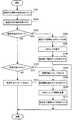
図27に示す第2の実施の形態の検索通信処理の実行中には、ステップS62において、リーダ制御部101により図28に示す移動速度検出処理が実行される。
まず、リーダ制御部101は、移動速度検出部78が備える加速度センサによって、ICリーダ7の移動速度を検出する(ステップS81)。While the search communication process of the second embodiment shown in FIG. 27 is being executed, the movement speed detection process shown in FIG. 28 is executed by the
First, the
次に、リーダ制御部101は、ステップS81において検出したICリーダ7の移動速度が、所定の速度より速いか否かを判定する(ステップS82)。ICリーダ7の移動速度が所定の速度より速い場合、リーダ制御部101は、ICリーダ7の移動速度が異常であることを示す速度異常メッセージを通知部16に出力させ(ステップS83)、その後、検索通信処理に復帰する一方、ICリーダ7の移動速度が所定の速度以下である場合、ICリーダ7の移動速度が適正であることを示す速度適正メッセージを通知部16に出力させ(ステップS84)、その後、検索通信処理に復帰する。 Next, the
次に、第2の実施の形態のICリーダによる非接触型ICチップに記憶されている情報の検索時における移動速度の検出の様子について説明する。ここでは、本実施の形態のICリーダ7を、前述した光ディスク3および光ディスクケース2と組み合わせて、非接触型ICチップ32に記録されている情報の検索に用いた場合の様子について説明する。 Next, how the moving speed is detected when searching for information stored in the non-contact type IC chip by the IC reader according to the second embodiment will be described. Here, a state in which the IC reader 7 of the present embodiment is used for searching information recorded on the non-contact
図29は、第2の実施の形態のICリーダによる移動速度の検出の際の様子を示す図である。
図29のように非接触型ICチップ32を搭載した光ディスク3を収容する、ブースタアンテナを搭載した光ディスクケース2が、立てられた状態で横に多数並べられているような場合に、第2の実施の形態のICリーダ7を移動させながら、ブースタアンテナ20のアンテナコイル22が設けられたケース側面に順次向けていくことで、非接触型ICチップ32に記録されている情報を順次読み取っていくことができる。これによって、各光ディスク3に搭載されている非接触型ICチップ32から、情報を検索することができる。FIG. 29 is a diagram illustrating a state when the moving speed is detected by the IC reader according to the second embodiment.
As shown in FIG. 29, when the
すなわち、図14と同様に、光ディスクケース2には、それぞれ前述したブースタアンテナユニットが備えられており、光ディスクケース2の側面側(図29の手前側)には、ブースタアンテナユニットのICリーダ側のアンテナコイル22が設けられている。 That is, as in FIG. 14, each of the
第1の実施の形態と同様に、ユーザがICリーダ7の検索ボタン153を長押ししながら、前面に設けられた第2のアンテナ部13を、それぞれの光ディスクケース2のアンテナコイル22に対して(図29の例では左から右に)順次かざしていくことによって、それぞれの光ディスク3に搭載された非接触型ICチップ32に記録された情報を読み取ることができる。このとき、本実施の形態のICリーダ7が備える移動速度検出部78によって、ICリーダ7の移動速度が検出される。そして、検出された移動速度が所定の速度(例えば、20mm/s)より速い場合には、ICリーダ7の通知部16から、移動速度が異常である旨を通知する速度異常メッセージが出力される。一方、検出された移動速度が所定の速度以下の場合には、ICリーダ7の通知部16から、移動速度が適正である旨を通知する速度適正メッセージが出力される。また、検索通信処理(図27)における非接触型ICチップ32の検出が正常に行われていれば、ICリーダ7の通知部16から、光ディスク3の非接触型ICチップ32を検出し、通信に成功した旨を通知する検出メッセージが出力される。 Similarly to the first embodiment, the user holds down the
速度異常メッセージ、速度適正メッセージ、および検出メッセージは、具体的には、ICリーダ7の投光部163から照射される照射光163aや、音声出力部164から出力される音声メッセージ164e、表示ディスプレイ161に表示される文字メッセージなどによって示される。 Specifically, the speed abnormality message, the speed appropriate message, and the detection message are the
そして、図29の検索通信処理の実行時において、非接触型ICチップ32の検出および通信に成功したICリーダ7は、その非接触型ICチップ32に記憶されている情報について検索を行う。 29, the IC reader 7 that has successfully detected and communicated with the non-contact
ここで、ICリーダ7の移動速度が速過ぎるか否かの基準となる所定の速度は、ICリーダ7と非接触型ICチップ32との間の通信における1回の通信シーケンスの時間やポーリング時間と、アンテナで通信可能な距離で決定される。 Here, the predetermined speed as a reference for determining whether or not the moving speed of the IC reader 7 is too fast is the time of one communication sequence and the polling time in the communication between the IC reader 7 and the non-contact
例えば、第2のアンテナ部13の第2のアンテナコイル131を、短軸方向と長軸方向とで外径が異なるように構成した場合において、ICリーダ7を短軸方向に移動させながら非接触型ICチップ32を検出すれば、短軸方向での通信可能距離が短くなる。従って、ポーリング時間が一定の場合は、第2のアンテナ部13のアンテナコイルの外径の狭さに応じて、その方向での移動速度を制限する必要がある。具体的には、第2のアンテナ部13の第2のアンテナコイル131の短軸方向で通信可能となる変位距離を±2mm(すなわちアンテナコイル131の中心を基準とした通信可能範囲で4mm)とし、ICリーダ7と非接触型ICチップ32との間の通信におけるポーリング時間間隔を0.2秒とすると、通信可能範囲である4mmを移動する間に少なくともポーリングが1回行われなければならないため、4/0.2=[20mm/s]未満の速度で移動させなければ、通信に失敗する可能性がある。 For example, in the case where the
なお、移動速度が速過ぎる場合は、並べられている光ディスクケース2を読み飛ばしている可能性もあることから、「移動が速すぎます!」との音声メッセージの出力の他にも、「2,3枚分戻って、読み取り直してください」との音声メッセージを出力してもよい。またさらに、何枚分戻って読み取り直すかどうかは、所定の速度の超えた状態での移動距離(移動速度の積分値)から、その移動距離が何枚分に相当するかを計算した上で、その枚数を音声メッセージとして出力してもよい。もちろん、その移動距離を「何mm戻ってください」と距離値で音声メッセージとして出力してもよい。 If the moving speed is too fast, there is a possibility of skipping the
以上説明した第2の実施の形態のICリーダ7によれば、速度異常メッセージとして、照射光163aの特定の発光パターン(例えば、ICリーダ7の移動速度が速過ぎる場合に点滅して照射光163aを出力)や、合成音声による音声メッセージ(例えば、ICリーダ7の移動速度が速過ぎる場合に、「移動が速過ぎます!」という音声メッセージ164e)などを出力することによって、ユーザにICリーダ7の移動速度が異常であることを通知することができる。 According to the IC reader 7 of the second embodiment described above, as a speed abnormality message, a specific light emission pattern of the
また、ICリーダ7の移動速度が所定の速度以下である場合など、移動速度が適正である場合には、速度異常メッセージとは異なる照射光163aの特定の発光パターンや、合成音声による速度が適正である旨を示す音声メッセージなどによる、速度適正メッセージを出力することによって、ユーザにICリーダ7の移動速度が適正であることを通知することができる。 Further, when the moving speed is appropriate, such as when the moving speed of the IC reader 7 is equal to or lower than a predetermined speed, the specific light emission pattern of the
以上の結果、ユーザがICリーダ7を移動させながら多数の光ディスクケース2に収容されている光ディスク3の非接触型ICチップ32に記録されている情報を検索する場合に、ユーザに対してICリーダ7の移動速度が適正であるか否かを通知することによって、検索時におけるユーザの適正な移動速度でICリーダ7を容易に移動させることができるので、検出エラーや読み飛ばしなどによる非接触型ICチップ32の検出漏れを防止することができる。 As a result, when the user searches the information recorded on the non-contact
[第3の実施の形態]
次に、第3の実施の形態について説明する。ICリーダによって検出した非接触型ICチップ32に記憶されている情報は、例えば、パーソナルコンピュータに移動して光ディスクの記録内容を管理したり、楽曲のタイトルやアーチスト名など、興味のあるコンテンツを特定する情報を知人に電子メールなどで送信したりするなどに活用し得るものである。そこで、取得した情報をそのまま他の用途に活用することができれば、大変便利である。このため、第3の実施の形態のICリーダ1は、外部通信部17によって、例えば携帯電話などの外部の情報端末機器に対して、ICリーダ1が検出した非接触型ICチップ32に記憶されている情報が転送可能である点で第1の実施の形態と異なる。なお、ICリーダ1や他の構成要素について、同一の構成要素については同一符号としており、説明を省略する。[Third Embodiment]
Next, a third embodiment will be described. The information stored in the non-contact
次に、第3の実施の形態のICリーダの動作について説明する。
まず、第3の実施の形態におけるメイン処理について説明する。本実施の形態のメイン処理では、本処理の実行時において、ユーザによる操作部15の操作により、情報転送メニューが選択された場合には、外部通信部17を介して外部の情報端末装置に光ディスク3の非接触型ICチップ32から取得した情報を転送する情報転送処理が実行される点が、第1の実施の形態と異なる。Next, the operation of the IC reader according to the third embodiment will be described.
First, the main process in the third embodiment will be described. In the main process of the present embodiment, when the information transfer menu is selected by the operation of the
図30は、第3の実施の形態のICリーダで実行されるメイン処理を説明するフローチャートである。
まず、ユーザによって操作部15が操作されると、ICリーダ1のリーダ制御部101は、ユーザによる操作部15の操作を検出する(ステップS91)。FIG. 30 is a flowchart illustrating main processing executed by the IC reader according to the third embodiment.
First, when the
次に、リーダ制御部101は、ステップS91でユーザによる表示ボタン152の操作を検出したか否かを判定し(ステップS92)、表示ボタン152の操作を検出していない場合には、ステップS94の処理に進む一方、表示ボタン152の操作を検出した場合には、表示通信処理を実行し(ステップS93)、その後、ステップS100の処理に進む。 Next, the
次に、リーダ制御部101は、ステップS91でユーザによる検索ボタン153の長押し操作(例えば、検索ボタン153を1秒以上押し続ける操作)を検出したか否かを判定し(ステップS94)、検索ボタン153の長押し操作を検出していない場合には、ステップS96の処理に進む一方、検索ボタン153の長押し操作を検出した場合には、検索通信処理を実行し(ステップS95)、その後、ステップS100の処理に進む。 Next, the
次に、リーダ制御部101は、ステップS91でユーザによる検索ボタン153の二度押し操作(例えば、検索ボタン153を1秒間に2回以上押す操作)を検出したか否かを判定し(ステップS96)、検索ボタン153の二度押し操作を検出していない場合には、ステップS100の処理に進む一方、検索ボタン153の二度押し操作を検出した場合には、検索条件取得処理を実行し(ステップS97)、その後、ステップS100の処理に進む。 Next, the
次に、リーダ制御部101は、ステップS91でユーザによる操作部15の入力ボタン151の操作による情報転送メニュー(図示省略)の選択を受け付けたか否かを判定し(ステップS98)、入力ボタン151による情報転送メニューの選択を受け付けていない場合には、ステップS100の処理に進む一方、入力ボタン151による情報転送メニューの選択を受け付けた場合には、情報転送処理を実行し(ステップS99)、その後、ステップS100の処理に進む。この情報転送処理は、光ディスク3の非接触型ICチップ32から取得した情報を、外部通信部17を通じて外部の情報端末装置に送信する処理であり、詳しくは図31において後述する。 Next, the
そして、リーダ制御部101は、ユーザによる操作が検出されている場合には、上記の処理を繰り返し(ステップS100)、ユーザによる操作の検出が終了した場合には、処理を終了する。 Then, the
次に、第3の実施の形態のメイン処理のステップS99で実行される情報転送処理について説明する。
図31は、第3の実施の形態のICリーダで実行される情報転送処理を説明するフローチャートである。Next, the information transfer process executed in step S99 of the main process according to the third embodiment will be described.
FIG. 31 is a flowchart illustrating information transfer processing executed by the IC reader according to the third embodiment.
第3の実施の形態のメイン処理においてユーザの入力ボタン151の操作による情報転送メニューの選択が受け付けられると、リーダ制御部101によって図31に示す情報転送処理が実行される。 When the selection of the information transfer menu by the user's operation of the
まず、リーダ制御部101は、入力ボタン151に対するユーザの操作による転送する情報の指定を受け付ける(ステップS101)。ユーザは、図示しない情報転送メニューにおいて、以前非接触型ICチップ32から取得した、図16〜図19に示すディスク主情報やディスク補助情報を指定することができる。 First, the
次に、リーダ制御部101は、入力ボタン151に対するユーザの操作による転送方法の指定を受け付ける(ステップS102)。ユーザは、図示しない情報転送メニューにおいて、QRコードの表示ディスプレイ161への表示やIrDAによる赤外線通信など、予め定められた転送方法を指定することができる。 Next, the
次に、リーダ制御部101は、ステップS102でユーザの入力ボタン151の操作によって指定された転送方法がQRコードであるか否かを判定する(ステップS103)。
指定された転送方法がQRコードである場合には、ステップS101で指定された転送する情報からQRコードを生成し(ステップS104)、生成したQRコードを表示ディスプレイ161に表示し(ステップS105)、ユーザによって転送の完了が確認されたことを示す転送完了確認の入力を受け付け(ステップS106)、その後、メイン処理に復帰する。Next, the
If the designated transfer method is a QR code, a QR code is generated from the information to be transferred designated in step S101 (step S104), and the generated QR code is displayed on the display 161 (step S105). A transfer completion confirmation input indicating that the transfer has been confirmed by the user is accepted (step S106), and then the process returns to the main process.
一方、指定された転送方法がQRコードでない場合には、リーダ制御部101は、ステップS102でユーザの入力ボタン151の操作によって指定された転送方法がIrDAであるか否かを判定する(ステップS107)。 On the other hand, when the designated transfer method is not a QR code, the
指定された転送方法がIrDAである場合には、送信先の情報端末装置の受信準備をユーザに促す受信準備メッセージを通知部16に出力し(ステップS108)、情報の転送の開始の指示である転送開始指示のユーザによる入力を受け付け(ステップS109)、ステップS101で指定された転送する情報をIrDAによって送信し(ステップS110)、ユーザによって転送の完了が確認されたことを示す転送完了確認の入力を受け付け(ステップS111)、その後、メイン処理に復帰する。 When the designated transfer method is IrDA, a reception preparation message that prompts the user to prepare for reception of the destination information terminal device is output to the notification unit 16 (step S108), which is an instruction to start information transfer. The transfer start instruction is received by the user (step S109), the information to be transferred specified in step S101 is transmitted by IrDA (step S110), and the transfer completion confirmation indicating that the transfer has been confirmed by the user is input. (Step S111), and then returns to the main process.
一方、指定された転送方法がIrDAでない場合には、情報の転送を中止することを示す転送中止メッセージを通知部16に出力し(ステップS112)、その後、メイン処理に復帰する。 On the other hand, if the designated transfer method is not IrDA, a transfer stop message indicating that the transfer of information is stopped is output to the notification unit 16 (step S112), and then the process returns to the main process.
受信準備メッセージ、および転送中止メッセージは、具体的には、ICリーダ7の投光部163から照射される照射光163aや、音声出力部164から出力される音声メッセージ、表示ディスプレイ161に表示される文字メッセージ、などによって示される。 Specifically, the reception preparation message and the transfer cancellation message are displayed on the
以上説明した第3の実施の形態のICリーダ1によれば、QRコードやIrDA通信によって、光ディスク3の非接触型ICチップ32から取得した情報を他の情報端末装置に送信することができる。この結果、光ディスク3の記録内容などの、検索によって取得した非接触型ICチップ32に記録されている情報を、そのまま活用することが可能になり、ユーザの利便性が向上するとともに、ICリーダと他の情報端末装置との相互利用による、音楽データや動画データなどの利用の促進が図れる。 According to the IC reader 1 of the third embodiment described above, information acquired from the non-contact
1,7……ICリーダ、2,50……光ディスクケース、3……光ディスク、10……主回路、11……第1のアンテナ部、13……第2のアンテナ部、15……操作部、16……通知部、17……外部通信部、20……ブースタアンテナ、20a……ブースタアンテナユニット、21,22,31……アンテナコイル、23,33,112,132……同調回路、26,36,56……中心孔、29a〜29d……受光部分、30……信号記録領域、32……非接触型ICチップ、34……チャッキング領域、51a……表面カバー部、51b……裏面カバー部、51c……ケース側面部、52a,52b……折り曲げ部、53a,235……ディスク載置面、53b,236……ディスク保持部、54a……冊子収容面、54b……係止部、78……移動速度検出部、101……リーダ制御部、111……第1のアンテナコイル、131……第2のアンテナコイル、151……入力ボタン、152……表示ボタン、153……検索ボタン、161……表示ディスプレイ、162……アンテナ発光部、163……投光部、163a,163b……照射光、164……音声出力部、231……ベース部、232……カバー部、233……ディスクトレイ、234……連結部、237……凸部、238……側面、411,412,413,414……ディスク主情報、421,422,423,424……ディスク補助情報、431〜436……検索表示画面 DESCRIPTION OF SYMBOLS 1,7 ... IC reader, 2,50 ... Optical disk case, 3 ... Optical disk, 10 ... Main circuit, 11 ... 1st antenna part, 13 ... 2nd antenna part, 15 ... Operation part , 16... Notification section, 17... External communication section, 20... Booster antenna, 20 a... Booster antenna unit, 21, 22, 31 ...... antenna coil, 23, 33, 112, 132 ...... tuning circuit, 26 , 36, 56... Center hole, 29a to 29d... Light receiving portion, 30... Signal recording area, 32... Non-contact type IC chip, 34 ... Chucking area, 51a. Back cover part, 51c..Case side face part, 52a, 52b..Folded part, 53a, 235..Disk mounting surface, 53b, 236..Disk holding part, 54a .... Booklet receiving surface, 54b..Locking , 78... Moving speed detection unit, 101... Reader control unit, 111... First antenna coil, 131... Second antenna coil, 151.
Claims (19)
Translated fromJapanese外形の1つの面に平板状に設けられた、ループ状またはスパイラル状の第1のアンテナと、
前記1つの面に対する側面に平板状に設けられて、ループ状またはスパイラル状の形状を有し、その短軸方向の大きさが前記第1のアンテナの短軸方向の大きさより小さく形成された第2のアンテナと、
前記第1のアンテナまたは前記第2のアンテナのいずれか一方を選択的に用いて前記非接触型ICチップと通信し、当該非接触型ICチップに記録された情報を取得する制御部と、
を有し、
前記制御部は、前記第2のアンテナを通じて前記非接触型ICチップから情報を取得する場合には、前記第2のアンテナを通じて取得した情報が、前記非接触型ICチップに記録された情報について検索を行うための検索条件に該当するか否かを判定することを特徴とする情報読み取り装置。In a portable information reader that reads information recorded on a non-contact IC chip,
A loop-shaped or spiral-shaped first antenna provided in a flat shape on one surface of the outer shape;
A flat plate is provided on a side surface with respect to the one surface, has a loop shape or a spiral shape, and has a short axis direction smaller than a short axis direction of the first antenna. Two antennas,
A controller that communicates with the non-contact type IC chip by selectively using either the first antenna or the second antenna, and acquires information recorded in the non-contact type IC chip;
Have
When the control unit acquires information from the non-contact type IC chip through the second antenna, the information acquired through the second antenna is searched for information recorded in the non-contact type IC chip. An information reading apparatus for determining whether or not a search condition for performing the process is satisfied.
第2の入力部と、
を有し、
前記制御部は、ユーザによる前記第1の入力部の操作を受け付けると、前記第1のアンテナを通じて前記非接触型ICチップに記録された情報を取得する一方、ユーザによる前記第2の入力部の操作を受け付けると、前記第2のアンテナを通じて前記非接触型ICチップから情報を取得するとともに、前記第2のアンテナを通じて取得した情報が、前記検索条件に該当するか否かを判定することを特徴とする請求項1記載の情報読み取り装置。A first input unit;
A second input unit;
Have
When the control unit receives an operation of the first input unit by the user, the control unit acquires information recorded in the non-contact type IC chip through the first antenna, while the second input unit by the user When an operation is accepted, information is acquired from the non-contact type IC chip through the second antenna, and it is determined whether the information acquired through the second antenna satisfies the search condition. The information reading apparatus according to claim 1.
前記第2の入力部は、前記第2のアンテナの近傍に設けられていることを特徴とする請求項2記載の情報読み取り装置。The first input unit is provided in the vicinity of the first antenna,
The information reading apparatus according to claim 2, wherein the second input unit is provided in the vicinity of the second antenna.
前記第2のアンテナの形成面の法線は、前記ユーザが当該情報読み取り装置を把持したときに、前記ユーザから見て前方を向いていることを特徴とする請求項4記載の情報読み取り装置。The normal of the formation surface of the first antenna is oriented in the vertical direction when the user grips the information reading device,
5. The information reading apparatus according to claim 4, wherein a normal line of a surface on which the second antenna is formed faces forward when viewed from the user when the user holds the information reading apparatus.
前記第2のアンテナは、前記光ディスクを収容する光ディスクケースに設けられたブースタアンテナの2つのアンテナコイルのうち、当該光ディスクケース内の前記光ディスクの記録面と垂直な側面に当接または近接して設けられた側面側アンテナコイルと電磁結合できるように構成され、
前記ブースタアンテナは、前記側面側アンテナコイルと、前記光ディスクケース内の前記光ディスクに設けられたアンテナコイルと電磁結合するディスク側アンテナコイルとが接続されて、それぞれが送受信する信号を中継するように構成され、
前記光ディスクケース上の前記側面側アンテナコイルに前記第2のアンテナが近接して配置されたとき、前記制御部は、当該光ディスクケース内の前記光ディスク上に設けられた前記非接触型ICチップから、前記ブースタアンテナを通じて情報を取得可能であることを特徴とする請求項1記載の情報読み取り装置。The first antenna is configured to be electromagnetically coupled to an antenna coil formed on an optical disk substrate of the optical disk along a circumferential direction thereof and to communicate with a non-contact type IC chip provided on the optical disk,
The second antenna is provided in contact with or close to a side surface perpendicular to the recording surface of the optical disc in the optical disc case, out of the two antenna coils of the booster antenna provided in the optical disc case accommodating the optical disc. Configured to be electromagnetically coupled to the side antenna coil
The booster antenna is configured such that the side antenna coil and a disk side antenna coil that is electromagnetically coupled to the antenna coil provided on the optical disk in the optical disk case are connected to relay signals transmitted and received by each. And
When the second antenna is disposed in proximity to the side antenna coil on the optical disc case, the control unit is configured from the non-contact IC chip provided on the optical disc in the optical disc case, The information reading apparatus according to claim 1, wherein information can be acquired through the booster antenna.
前記制御部は、前記第2のアンテナを通じて前記非接触型ICチップから情報を取得する場合には、前記第2のアンテナを通じて取得した情報が、前記検索条件入力部によって受け付けられた前記検索条件に該当するか否かを判定することを特徴とする請求項1記載の情報読み取り装置。A search condition input unit for receiving input of the search condition;
When the control unit acquires information from the non-contact type IC chip through the second antenna, the information acquired through the second antenna is included in the search condition received by the search condition input unit. The information reading apparatus according to claim 1, wherein it is determined whether or not the information is applicable.
前記制御部は、前記第2のアンテナを通じて前記非接触型ICチップから情報を取得する場合には、前記第2のアンテナを通じて取得した情報が、前記検索条件に該当するか否かを判定し、前記第2のアンテナを通じて取得した情報が前記検索条件に該当すると判定した場合には、前記通知部に前記検索条件に該当する情報が前記非接触型ICチップに記録されている旨を通知させることを特徴とする請求項1記載の情報読み取り装置。A notification unit for notifying a user of the state of the information reading device;
When the control unit acquires information from the non-contact IC chip through the second antenna, the control unit determines whether the information acquired through the second antenna satisfies the search condition. If it is determined that the information acquired through the second antenna satisfies the search condition, the notification unit is notified that information corresponding to the search condition is recorded in the non-contact type IC chip. The information reading apparatus according to claim 1.
前記制御部は、前記第2のアンテナを通じて取得した情報が前記検索条件に該当すると判定した場合には、前記通知部に前記検索条件に該当する情報が前記非接触型ICチップに記録されている旨を通知させる音声メッセージを出力することを特徴とする請求項8記載の情報読み取り装置。The notification unit can output a voice message;
When the control unit determines that the information acquired through the second antenna corresponds to the search condition, information corresponding to the search condition is recorded in the non-contact type IC chip in the notification unit. The information reading apparatus according to claim 8, wherein a voice message for notifying is output.
ユーザに当該情報読み取り装置の状態を通知する通知部と、
を有し、
前記制御部は、前記第2のアンテナによる読み取り動作中に、前記速度検出部によって検出された移動速度が、所定の速度より速いか否かを判定し、当該移動速度が所定の速度より速い場合には、前記通知部によってユーザに対して異常を通知させることを特徴とする請求項1記載の情報読み取り装置。A speed detector for detecting the moving speed of the information reading device;
A notification unit for notifying the user of the state of the information reading device;
Have
The control unit determines whether or not the moving speed detected by the speed detecting unit is faster than a predetermined speed during the reading operation by the second antenna, and the moving speed is faster than the predetermined speed. The information reading device according to claim 1, wherein the notification unit notifies the user of an abnormality.
前記通知部は、情報を表示する表示画面を有し、
前記制御部は、前記通知部が有する前記表示画面に前記第1のアンテナにより取得した前記非接触型ICチップに記録された情報、または当該情報に対応付けられた他の情報のうち、少なくともいずれか一方を表示させることを特徴とする請求項1記載の情報読み取り装置。A notification unit for notifying a user of the state of the information reading device;
The notification unit has a display screen for displaying information,
The control unit includes at least one of information recorded on the non-contact type IC chip acquired by the first antenna on the display screen of the notification unit, or other information associated with the information. 2. The information reading apparatus according to claim 1, wherein one of the two is displayed.
前記通知部は、発光する発光部を有し、
前記制御部は、前記第1のアンテナおよび前記第2のアンテナのうち少なくともいずれか一方によって前記非接触型ICチップと通信すると、前記通知部が有する前記発光部を発光させることを特徴とする請求項1記載の情報読み取り装置。A notification unit for notifying the user of the state of the information reading device;
The notification unit includes a light emitting unit that emits light,
The control unit causes the light emitting unit included in the notification unit to emit light when communicating with the non-contact type IC chip through at least one of the first antenna and the second antenna. Item 1. The information reading device according to Item 1.
前記通知部は、前記第2のアンテナの前方に向けて発光する発光部を有し、
前記制御部は、前記第2のアンテナによって取得した情報が前記検索条件に該当する場合には、前記通知部が有する前記発光部を発光させることを特徴とする請求項1記載の情報読み取り装置。A notification unit for notifying a user of the state of the information reading device;
The notification unit includes a light emitting unit that emits light toward the front of the second antenna;
2. The information reading apparatus according to claim 1, wherein when the information acquired by the second antenna satisfies the search condition, the control unit causes the light emitting unit included in the notification unit to emit light.
前記制御部は、前記外部通信部によって前記検索条件を前記他の情報機器から受信可能であることを特徴とする請求項1記載の情報読み取り装置。Having an external communication unit that can communicate with other information devices,
The information reading apparatus according to claim 1, wherein the control unit is capable of receiving the search condition from the other information device by the external communication unit.
前記制御部は、前記外部通信部によって前記検索条件に基づく前記非接触型ICチップの検索結果を前記他の情報機器に送信可能であることを特徴とする請求項1記載の情報読み取り装置。Having an external communication unit that can communicate with other information devices,
The information reading apparatus according to claim 1, wherein the control unit can transmit the search result of the non-contact type IC chip based on the search condition to the other information device by the external communication unit.
前記情報読み取り装置に備えられた制御部が、
ループ状またはスパイラル状の第1のアンテナ、およびループ状またはスパイラル状の形状を有し、その短軸方向の大きさが前記第1のアンテナの短軸方向の大きさより小さく形成された第2のアンテナのいずれか一方を選択し、選択したアンテナを通じて前記非接触型ICチップと通信し、当該非接触型ICチップに記録された情報を取得し、
前記第2のアンテナを通じて前記非接触型ICチップから情報を取得する場合には、前記非接触型ICチップに記録された情報について検索を行うための検索条件に該当するか否かを判定することを特徴とする情報読み取り方法。In an information reading method of reading information recorded on a non-contact type IC chip by a portable information reading device,
The control unit provided in the information reading device,
A first antenna having a loop shape or a spiral shape, and a second shape having a loop shape or a spiral shape and having a size in a short axis direction smaller than a size in a short axis direction of the first antenna. Select any one of the antennas, communicate with the non-contact type IC chip through the selected antenna, obtain information recorded on the non-contact type IC chip,
When acquiring information from the non-contact IC chip through the second antenna, it is determined whether or not a search condition for searching for information recorded on the non-contact IC chip is satisfied. An information reading method characterized by the above.
Priority Applications (2)
| Application Number | Priority Date | Filing Date | Title |
|---|---|---|---|
| JP2007251247AJP2009080761A (en) | 2007-09-27 | 2007-09-27 | Information reader, and information reading method |
| US12/211,312US8181873B2 (en) | 2007-09-27 | 2008-09-16 | Information reading apparatus and information reading method |
Applications Claiming Priority (1)
| Application Number | Priority Date | Filing Date | Title |
|---|---|---|---|
| JP2007251247AJP2009080761A (en) | 2007-09-27 | 2007-09-27 | Information reader, and information reading method |
Publications (1)
| Publication Number | Publication Date |
|---|---|
| JP2009080761Atrue JP2009080761A (en) | 2009-04-16 |
Family
ID=40507048
Family Applications (1)
| Application Number | Title | Priority Date | Filing Date |
|---|---|---|---|
| JP2007251247APendingJP2009080761A (en) | 2007-09-27 | 2007-09-27 | Information reader, and information reading method |
Country Status (2)
| Country | Link |
|---|---|
| US (1) | US8181873B2 (en) |
| JP (1) | JP2009080761A (en) |
Cited By (1)
| Publication number | Priority date | Publication date | Assignee | Title |
|---|---|---|---|---|
| JP2010263690A (en)* | 2009-05-01 | 2010-11-18 | Panasonic Electric Works Co Ltd | Transmission system |
Families Citing this family (6)
| Publication number | Priority date | Publication date | Assignee | Title |
|---|---|---|---|---|
| US7886315B2 (en)* | 2007-01-30 | 2011-02-08 | Sony Corporation | Optical disc case, optical disc tray, card member, and manufacturing method |
| JP4393559B2 (en)* | 2008-02-28 | 2010-01-06 | 株式会社東芝 | Recording apparatus and broadcast receiving apparatus |
| EP2362329B1 (en)* | 2010-02-25 | 2014-07-23 | Skidata Ag | Device for increasing the read/write range of a RFID system |
| JP6216625B2 (en)* | 2012-11-29 | 2017-10-18 | トッパン・フォームズ株式会社 | Radio IC mounted article and manufacturing method thereof |
| DE102013012339A1 (en)* | 2013-07-25 | 2015-01-29 | Giesecke & Devrient Gmbh | External secure unit |
| EP3188914A4 (en)* | 2014-09-05 | 2018-05-02 | Codonics, Inc. | Consumable carrier with code reader |
Family Cites Families (8)
| Publication number | Priority date | Publication date | Assignee | Title |
|---|---|---|---|---|
| US6082621A (en)* | 1992-04-02 | 2000-07-04 | Symbol Technologies, Inc. | Interface between threshold processing digitizer for bar code reader |
| JP3882218B2 (en) | 1996-03-04 | 2007-02-14 | ソニー株式会社 | optical disk |
| US5936527A (en)* | 1998-02-10 | 1999-08-10 | E-Tag Systems, Inc. | Method and apparatus for locating and tracking documents and other objects |
| JP2001247209A (en) | 2000-03-06 | 2001-09-11 | Sony Corp | Information inspection device and information inspection method |
| JP4200435B2 (en)* | 2002-09-10 | 2008-12-24 | ソニー株式会社 | Information processing apparatus and method, recording medium, and program |
| JP4364718B2 (en) | 2004-05-26 | 2009-11-18 | 日立マクセル株式会社 | Contactless communication system |
| WO2007009048A2 (en)* | 2005-07-13 | 2007-01-18 | Kestrel Wireless Inc. | Devices, packaging, and methods for rf communication with targets |
| JP4696917B2 (en)* | 2006-01-10 | 2011-06-08 | ソニー株式会社 | Optical disc recording / reproducing apparatus |
- 2007
- 2007-09-27JPJP2007251247Apatent/JP2009080761A/enactivePending
- 2008
- 2008-09-16USUS12/211,312patent/US8181873B2/ennot_activeExpired - Fee Related
Cited By (1)
| Publication number | Priority date | Publication date | Assignee | Title |
|---|---|---|---|---|
| JP2010263690A (en)* | 2009-05-01 | 2010-11-18 | Panasonic Electric Works Co Ltd | Transmission system |
Also Published As
| Publication number | Publication date |
|---|---|
| US8181873B2 (en) | 2012-05-22 |
| US20090084846A1 (en) | 2009-04-02 |
Similar Documents
| Publication | Publication Date | Title |
|---|---|---|
| JP2009080761A (en) | Information reader, and information reading method | |
| US9070063B2 (en) | Radio frequency identification (RFID) tag for an item having a conductive layer included or attached | |
| US7044373B1 (en) | Radio frequency identification systems applications | |
| JP5195263B2 (en) | Information transmission medium management system | |
| JP2008207875A (en) | Optical disk case, optical disk tray, card member and manufacturing method | |
| US20130134226A1 (en) | Radio frequency identification library slanted cavity device | |
| EP2605245A2 (en) | Mobile communication device | |
| KR20070090945A (en) | Radio Frequency Identification (RRFID) tags for articles with or with conductive layers attached | |
| JPH10334198A (en) | Document storage management system | |
| JP4696917B2 (en) | Optical disc recording / reproducing apparatus | |
| US7772980B2 (en) | Method and systems for localizing objects using capacitively coupled RFIDs | |
| US20070257799A1 (en) | Method and structure for localizing objects using daisy chained rfid tags | |
| JP2009230707A (en) | Information reader, and information reading method | |
| EP1537577A1 (en) | Information carrier drive device provided with a double antenna | |
| JP3802717B2 (en) | Article and article management system | |
| JP2005339663A (en) | Information storage medium case | |
| JP2008114040A (en) | Discrete type prize | |
| JP2013084139A (en) | Identification information access device | |
| JP4445362B2 (en) | Wireless tag reader | |
| JP2004059320A (en) | System for storing and controlling books and method of using the system | |
| JP2007238236A (en) | Goods management system | |
| JP2007183788A (en) | Optical disk recording and reproducing device and optical disk recording and reproducing method | |
| JP4706903B2 (en) | Radio tag information communication device and radio tag cartridge | |
| JP2006254241A (en) | Content recommendation system, communication terminal device and method for content recommendation | |
| WO2025153526A1 (en) | Wireless music token and cloud |