JP2009078119A - Slot machine which pays out prescribed number of credits when frequency of game reaches specified value - Google Patents
Slot machine which pays out prescribed number of credits when frequency of game reaches specified valueDownload PDFInfo
- Publication number
- JP2009078119A JP2009078119AJP2008061195AJP2008061195AJP2009078119AJP 2009078119 AJP2009078119 AJP 2009078119AJP 2008061195 AJP2008061195 AJP 2008061195AJP 2008061195 AJP2008061195 AJP 2008061195AJP 2009078119 AJP2009078119 AJP 2009078119A
- Authority
- JP
- Japan
- Prior art keywords
- game
- symbols
- main cpu
- insurance mode
- image
- Prior art date
- Legal status (The legal status is an assumption and is not a legal conclusion. Google has not performed a legal analysis and makes no representation as to the accuracy of the status listed.)
- Pending
Links
Images


Classifications
- G—PHYSICS
- G07—CHECKING-DEVICES
- G07F—COIN-FREED OR LIKE APPARATUS
- G07F17/00—Coin-freed apparatus for hiring articles; Coin-freed facilities or services
- G07F17/32—Coin-freed apparatus for hiring articles; Coin-freed facilities or services for games, toys, sports, or amusements
- G—PHYSICS
- G07—CHECKING-DEVICES
- G07F—COIN-FREED OR LIKE APPARATUS
- G07F17/00—Coin-freed apparatus for hiring articles; Coin-freed facilities or services
- G07F17/32—Coin-freed apparatus for hiring articles; Coin-freed facilities or services for games, toys, sports, or amusements
- G07F17/3244—Payment aspects of a gaming system, e.g. payment schemes, setting payout ratio, bonus or consolation prizes
Landscapes
- Physics & Mathematics (AREA)
- General Physics & Mathematics (AREA)
- Slot Machines And Peripheral Devices (AREA)
- Game Rules And Presentations Of Slot Machines (AREA)
Abstract
Description
Translated fromJapanese本発明は、ゲーム回数が特定回数に達した際に所定数のクレジットのペイアウトを行うスロットマシンに関するものである。 The present invention relates to a slot machine that pays out a predetermined number of credits when the number of games reaches a specific number.
従来、スロットマシン(例えば、特許文献1参照)が設置された施設においては、コインや現金等の各種の遊技媒体をスロットマシンに投入することにより、遊技を行うことができる。そして、各スロットマシンは、遊技の進行によって発生する入賞状態(遊技の結果)によって配当を払い出すようになっている。 Conventionally, in a facility where a slot machine (for example, see Patent Document 1) is installed, a game can be played by inserting various game media such as coins and cash into the slot machine. Each slot machine pays out a payout according to a winning state (game result) generated by the progress of the game.
また、従来のスロットマシンとしては、クレジットの損失が一定額になると、その遊技者に対する還元が行われるスロットマシンがあった(例えば、特許文献2参照)。すなわち、損失がいわゆる天井値に到達すると、一定量の払出しを行うスロットマシンが知られている。
本発明は、新たなエンターテイメント性を備えたスロットマシンを提供することを目的とする。 An object of this invention is to provide the slot machine provided with new entertainment property.
(1) 複数のシンボルを表示するシンボル表示デバイスと、クレジットのペイアウトに関連するポイントを記憶するメモリと、コントローラと、を備え、当該コントローラは、(a)ベットを受け付けた後、前記シンボル表示デバイスにより前記複数のシンボルの再配置を行い、前記複数のシンボルの再配置の状態に応じた数のクレジットのペイアウトを行うゲームを実行し、(b)前記複数のシンボルの再配置の状態が所定のシンボル組合せとなる場合には、所定数のポイントを累積加算して前記メモリに記憶し、(c)所定の条件により、保険無モードから保険有モードに移行し、(d)前記保険有モードに移行した場合に、前記保険有モードに移行してから行われたゲーム回数をカウントし、(e)(d)の処理によりカウントされたゲーム回数が特定回数に達した際に、前記メモリに記憶されたポイントに応じた数のクレジットのペイアウトを行うことを特徴とするスロットマシン。 (1) A symbol display device that displays a plurality of symbols, a memory that stores points related to credit payout, and a controller. (A) After receiving a bet, the controller displays the symbol display device. To execute a game in which the plurality of symbols are rearranged and a payout of a number of credits corresponding to the rearrangement state of the plurality of symbols is executed, and (b) the rearrangement state of the plurality of symbols is predetermined. In the case of a symbol combination, a predetermined number of points are cumulatively added and stored in the memory, (c) a transition from the non-insurance mode to the insurance mode is performed according to predetermined conditions, and (d) the insurance mode is set. When transitioned, the number of games played after transitioning to the insurance mode is counted and counted by the processes (e) and (d). When the number of games reaches the specific number, the slot machine which is characterized in that the number of credits payout corresponding to the point stored in the memory.
(1)の発明によるスロットマシンは、(a)複数のシンボルの再配置の状態に応じた数のクレジットのペイアウトを行うゲームを実行し、(b)複数のシンボルの再配置の状態が所定のシンボル組合せとなる場合には、所定数のポイントを累積加算してメモリに記憶し、(c)所定の条件により、保険無モードから保険有モードに移行し、(d)保険有モードに移行してから行われたゲーム回数をカウントし、(e)カウントされたゲーム回数が特定回数に達した際に、メモリに記憶されたポイントに応じた数のクレジットのペイアウトを行う。 The slot machine according to the invention of (1) executes a game in which (a) a payout of a number of credits corresponding to a rearrangement state of a plurality of symbols is executed, and (b) a rearrangement state of the plurality of symbols is predetermined. In the case of a symbol combination, a predetermined number of points are cumulatively added and stored in the memory. (C) Transition from the non-insurance mode to the insurance mode according to predetermined conditions, and (d) shift to the insurance mode. (E) When the counted number of games reaches a specific number, the number of credits corresponding to the points stored in the memory is paid out.
(2) 複数のシンボルを表示するシンボル表示デバイスと、クレジットのペイアウトに関連するポイントを記憶するメモリと、コントローラと、を備え、当該コントローラは、(a)ベットを受け付けた後、前記シンボル表示デバイスにより前記複数のシンボルの再配置を行い、前記複数のシンボルの再配置の状態に応じた数のクレジットのペイアウトを行うゲームを実行し、(b)前記複数のシンボルの再配置の状態が所定のシンボル組合せとなる場合には、所定数のポイントを累積加算して前記メモリに記憶し、(c)所定の条件により、保険無モードから保険有モードに移行し、(d)前記保険有モードに移行した場合に、前記保険有モードに移行してから行われたゲーム回数をカウントし、(e)(d)の処理によりカウントされたゲーム回数が特定回数に達した際に、前記メモリに記憶されたポイントに応じた数のクレジットのペイアウトを行い、(f)前記メモリに記憶されたポイントが所定値に到達した場合には、(e)の処理においてペイアウトを行うクレジットの数を所定量増加させることを特徴とするスロットマシン。 (2) A symbol display device that displays a plurality of symbols, a memory that stores points related to credit payouts, and a controller. (A) After receiving a bet, the controller displays the symbol display device. To execute a game in which the plurality of symbols are rearranged and a payout of a number of credits corresponding to the rearrangement state of the plurality of symbols is executed, and (b) the rearrangement state of the plurality of symbols is predetermined. In the case of a symbol combination, a predetermined number of points are cumulatively added and stored in the memory. (C) The non-insurance mode is shifted to the insured mode under a predetermined condition. When transitioned, the number of games played after transitioning to the insurance mode is counted and counted by the processes (e) and (d). When the number of games reaches a specific number, payout of credits corresponding to the number of points stored in the memory is performed. (F) When the points stored in the memory reach a predetermined value, A slot machine, wherein the number of credits to be paid out is increased by a predetermined amount in the process of e).
(2)の発明によるスロットマシンは、(a)複数のシンボルの再配置の状態に応じた数のクレジットのペイアウトを行うゲームを実行し、(b)複数のシンボルの再配置の状態が所定のシンボル組合せとなる場合には、所定数のポイントを累積加算してメモリに記憶し、(c)所定の条件により、保険無モードから保険有モードに移行し、(d)保険有モードに移行してから行われたゲーム回数をカウントし、(e)カウントされたゲーム回数が特定回数に達した際に、メモリに記憶されたポイントに応じた数のクレジットのペイアウトを行い、(f)当該ポイントが所定値に到達した場合には、(e)の処理においてペイアウトを行うクレジットの数を所定量増加させる。 The slot machine according to the invention of (2) executes a game in which (a) a payout of a number of credits corresponding to a rearrangement state of a plurality of symbols is executed, and (b) a rearrangement state of the plurality of symbols is predetermined. In the case of a symbol combination, a predetermined number of points are cumulatively added and stored in the memory. (C) Transition from the non-insurance mode to the insurance mode according to predetermined conditions, and (d) shift to the insurance mode. (E) When the counted number of games reaches a specific number, payout of credits corresponding to the number of points stored in the memory is performed. Reaches the predetermined value, the number of credits to be paid out is increased by a predetermined amount in the process (e).
(3) 複数のシンボルを表示するシンボル表示デバイスと、クレジットのペイアウトに関連するポイントを記憶するメモリと、プレーヤがクレジットのペイアウトを受けることを決定するための入力を受け付ける入力デバイスと、コントローラと、を備え、当該コントローラは、(a)ベットを受け付けた後、前記シンボル表示デバイスに対して前記複数のシンボルの再配置を行い、前記複数のシンボルの再配置の状態に応じた数のクレジットのペイアウトを行うゲームを実行し、(b)前記複数のシンボルの再配置の状態が所定のシンボル組合せとなる場合には、所定数のポイントを累積加算して前記メモリに記憶し、(c)所定の条件により、保険無モードから保険有モードに移行し、(d)前記保険有モードに移行した場合に、前記保険有モードに移行してから行われたゲーム回数をカウントし、(e)(d)の処理によりカウントされたゲーム回数が特定回数に達した際に、前記入力デバイスが前記入力を受け付けた場合には前記メモリに記憶されたポイントに応じた数のクレジットのペイアウトを行い、(f)前記メモリに記憶されたポイントが所定値に到達した場合には、(e)の処理においてペイアウトを行うクレジットの数を所定量増加させることを特徴とするスロットマシン。 (3) a symbol display device for displaying a plurality of symbols, a memory for storing points related to credit payout, an input device for receiving an input for determining that the player receives credit payout, a controller, And (a) after accepting a bet, the controller rearranges the plurality of symbols to the symbol display device, and pays out a number of credits according to the rearrangement state of the plurality of symbols. (B) If the rearrangement state of the plurality of symbols is a predetermined symbol combination, a predetermined number of points are accumulated and stored in the memory, and (c) a predetermined Depending on the conditions, the mode shifts from the non-insurance mode to the insurance mode, and (d) When the number of games played since the transition to the rugged mode is counted, and the input device accepts the input when the number of games counted by the processes (e) and (d) reaches a specific number Pays out the number of credits corresponding to the points stored in the memory, and (f) credits for paying out in the process of (e) when the points stored in the memory reach a predetermined value. A slot machine characterized by increasing the number of a predetermined amount.
(3)の発明によるスロットマシンは、(a)複数のシンボルの再配置の状態に応じた数のクレジットのペイアウトを行うゲームを実行し、(b)複数のシンボルの再配置の状態が所定のシンボル組合せとなる場合には、所定数のポイントを累積加算してメモリに記憶し、(c)所定の条件により、保険無モードから保険有モードに移行し、(d)保険有モードに移行してから行われたゲーム回数をカウントし、(e)カウントされたゲーム回数が特定回数に達した際に、入力デバイスが、プレーヤがクレジットのペイアウトを受けることを決定するための入力を受け付けた場合には、メモリに記憶されたポイントに応じた数のクレジットのペイアウトを行い、(f)当該ポイントが所定値に到達した場合には、(e)の処理においてペイアウトを行うクレジットの数を所定量増加させる。 The slot machine according to the invention of (3) executes (a) a game that pays out a number of credits according to the rearrangement state of a plurality of symbols, and (b) the rearrangement state of the plurality of symbols is predetermined. In the case of a symbol combination, a predetermined number of points are cumulatively added and stored in the memory. (C) Transition from the non-insurance mode to the insurance mode according to predetermined conditions, and (d) shift to the insurance mode. (E) When the input device accepts an input to determine that the player will receive a credit payout when the counted number of games reaches a specific number The payout of the number of credits corresponding to the points stored in the memory is performed, and (f) when the points reach a predetermined value, the payout is performed in the process of (e). The number of credits for performing the door is increased by a predetermined amount.
本発明によれば、新たなエンターテイメント性を備えたスロットマシンを提供することができる。 ADVANTAGE OF THE INVENTION According to this invention, the slot machine provided with new entertainment property can be provided.
以下、本発明の実施形態について、図面に基づいて説明する。 Hereinafter, embodiments of the present invention will be described with reference to the drawings.
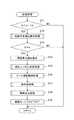
具体的な詳細については後述するが、図1に示す様に、本発明に係る遊技機10のメインCPU41は、複数のシンボルの再配置の状態に応じた数のクレジットのペイアウトを行うゲームを実行し(ステップS1001)、所定の条件により、保険無モードから保険有モードに移行し(ステップS1002)、保険有モードに移行してから行われたゲーム回数をカウントし(ステップS1003)、複数のシンボルの再配置の状態が所定のシンボル組合せとなる場合には、所定数のポイントを累積加算してメモリに記憶し(ステップS1004)、カウントされたゲーム回数が特定回数に達した際に、メモリに記憶されたポイントに応じた数のクレジットのペイアウトを行う(ステップS1005)。 Although specific details will be described later, as shown in FIG. 1, the
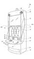
図2は、本発明の一実施形態に係る遊技機を模式的に示す斜視図である。本実施形態において、遊技機10は、スロットマシンである。ただし、本発明において、遊技機としては、スロットマシンに限定されず、例えば、ビデオスロットマシン、ビデオカードゲーム機等のいわゆるシングルゲーム機であってもよく、競馬ゲームやビンゴゲームや宝くじ等のように結果が表示されるまでに所定の時間を要するゲームを行ういわゆるマスゲーム機(マルチ・ターミナル・ゲーミングマシン)等であってもよい。 FIG. 2 is a perspective view schematically showing a gaming machine according to an embodiment of the present invention. In the present embodiment, the
遊技機10では、クレジットとして、コイン、紙幣又はこれらに相当する電子的な有価情報が用いられるものである。ただし、本発明において、クレジットとしては、特に限定されるものではなく、例えば、メダル、トークン、電子マネーを挙げることができる。 In the
図2は、本発明の一実施形態に係る遊技機を模式的に示す斜視図である。遊技機10は、キャビネット11を備えている。キャビネット11の内部には、3個のリール14(14L、14C、14R)が回転可能に設けられている。各リール14の外周面には、22個の図柄(以下、シンボルともいう)からなるシンボル列が描かれている。 FIG. 2 is a perspective view schematically showing a gaming machine according to an embodiment of the present invention. The
各リール14の前方には、下側画像表示パネル16が設けられている。下側画像表示パネル16は、透明液晶パネルを備えていて、遊技中には、遊技に関する各種の情報や演出画像等が表示される。下側画像表示パネル16は、本発明における画像の出力装置に相当するものである。下側画像表示パネル16には、クレジット数表示部31及びペイアウト数表示部32が設定されている。クレジット数表示部31には、クレジットされたコインの枚数が画像によって表示される。ペイアウト数表示部32には、入賞ライン上に再配置されたシンボルの組合せが所定の組合せであった場合に払い出されるコインの数が画像によって表示される。 A lower
下側画像表示パネル16には、その背面を視認可能な3個の表示窓15(15L、15C、15R)が形成されていて、各表示窓15を介して各リール14の外周面に描かれたシンボルがそれぞれ3個ずつ表示される。下側画像表示パネル16には、3個の表示窓15を水平に横切る1本の入賞ラインが形成されている。入賞ラインは、シンボルの組合せを規定するものである。入賞ライン上に再配置されたシンボルの組合せが所定の組合せであった場合に、その組合せとコインの投入数(BET数)とに応じた枚数のコインが払い出される。 The lower
なお、本発明においては、例えば、3個の表示窓15を水平に又は斜めに横切る複数本の入賞ラインが形成されていて、コインの投入数に応じた数の入賞ラインが有効化され、有効化された入賞ライン上に再配置されたシンボルの組合せが所定の組合せであった場合に、その組合せに応じた枚数のコインが払い出されることとしてもよい。 In the present invention, for example, a plurality of pay lines are formed which cross the three
更に、下側画像表示パネル16の前面には、図示しないが、タッチパネル69が設けられていて、プレイヤはタッチパネル69を操作して各種の指示を入力することができる。 Further, although not shown, a
下側画像表示パネル16の下方には、プレイヤによって遊技進行に係る指示が入力される複数のボタン23〜27からなるコントロールパネル20と、コインをキャビネット11内に受け入れるコイン受入口21と、紙幣識別器22とが設けられている。 Below the lower
コントロールパネル20には、スピンボタン23と、チェンジボタン24と、キャッシュアウトボタン25と、1−BETボタン26と、最大BETボタン27とが設けられている。スピンボタン23は、リール14の回転を開始させる指示を入力するためのものである。チェンジボタン24は、遊技施設の係員に両替を要求する際に用いられるものである。キャッシュアウトボタン25は、クレジットされているコインをコイントレイ18に払い出す指示を入力するためのものである。 The
1−BETボタン26は、クレジットされているコインのうち、1枚のコインを遊技に賭ける指示を入力するためのものである。最大BETボタン27は、クレジットされているコインのうち、1回の遊技に賭けることが可能な最大枚数(本実施形態では50枚)のコインを遊技に賭ける指示を入力するためのものである。 The 1-
なお、本発明において、クレジットの投入とは、クレジットが消費されることをいう。クレジットが消費される場合には、クレジットが遊技に賭けられる場合と、後述する保険有モードに移行するためにクレジットが消費される場合とが含まれる。例えば、コイン受入口21に投入されたコインが、直接遊技に賭けられる場合、コイン受入口21へのコインの投入が、クレジットの投入に相当する。ただし、本実施形態のように、コイン受入口21へコインが投入されると、一旦クレジットされ、1−BETボタン26又は最大BETボタン27が操作されると、クレジットされたコインが遊技に賭けられる場合、クレジットされたコインが遊技に賭けられることが、クレジットの投入に相当する。 In the present invention, the insertion of credit means that the credit is consumed. The case where the credit is consumed includes the case where the credit is bet on the game and the case where the credit is consumed for shifting to the insurance mode described later. For example, when a coin inserted into the
紙幣識別器22は、紙幣の適否を識別するとともに正規の紙幣をキャビネット11内に受け入れるものである。 The
キャビネット11の前面には、上側画像表示パネル33が設けられている。上側画像表示パネル33は、液晶パネルを備えていて、例えば、演出画像、遊技内容の紹介や遊技のルールの説明を表す画像が表示される。本実施形態においては、上側画像表示パネル33も、下側画像表示パネル16と同様に、本発明における画像の出力装置に相当するものである。なお、本発明においては、下側画像表示パネル16及び上側画像表示パネル33のいずれか一方が、画像の出力装置に相当するものであってもよい。 An upper
また、キャビネット11には、スピーカ29が設けられている。スピーカ29は、本発明における音の出力装置に相当するものである。下側画像表示パネル16の下側には、カードリーダ36と、データ表示器37と、キーパッド38とが設けられている。 The
カードリーダ36は、スマートカードからのデータの読み取り及びスマートカードへのデータの書き込みを行うものである。スマートカードは、プレイヤが所持するカードであり、例えば、プレイヤを識別するためのデータ、プレイヤが行った遊技の履歴に関するデータが記憶される。スマートカードには、コイン、紙幣又はクレジットに相当するデータが記憶されることとしてもよい。また、スマートカードにかえて、磁気ストライプカードを採用してもよい。データ表示器37は、蛍光ディスプレイ等からなり、例えば、カードリーダ36が読み取ったデータや、プレイヤによってキーパッド38を介して入力されたデータを表示するものである。 The
図3は、各リールの外周面に描かれたシンボルの列を示した模式図である。左リール14L、中リール14C及び右リール14Rの外周面には、それぞれ22個のシンボルが描かれている。各リール14に描かれたシンボルの列は、互いに異なっている。各シンボルの列は、「DO」、「3B」、「2B」、「CHERRY」、「1B」、「PLUM」、「AB」、「7」、「DORA」のシンボルが組合されて構成されている。 FIG. 3 is a schematic diagram showing a column of symbols drawn on the outer peripheral surface of each reel. Twenty-two symbols are drawn on the outer peripheral surfaces of the
「DO」、「3B」、「2B」、「CHERRY」、「1B」、「PLUM」、「AB」は、入賞ライン上に3つ再配置された場合に、予め定められたクレジット数がプレイヤの所有するクレジットとして追加される(図20参照)。また、「CHERRY」については、入賞ライン上に1つ又は2つ再配置された場合であっても、その数に応じて、予め定められたクレジット数がプレイヤの所有するクレジットとして追加される(図20参照)。 When “DO”, “3B”, “2B”, “CHERRY”, “1B”, “PLUM”, and “AB” are rearranged on the pay line, a predetermined number of credits is given to the player. (See FIG. 20). Further, regarding “CHERRY”, even if one or two are rearranged on the winning line, a predetermined number of credits is added as credits owned by the player according to the number (“CHERRY”) ( FIG. 20).
「7」は、ボーナスゲームトリガー(ボーナスゲームに移行するためのシンボル)である。「7」が入賞ライン上に3つ再配置された場合には、ボーナスゲームに移行することができる。本実施形態において、ボーナスゲームは、フリーゲーム(コインをBETすることなく所定回数にわたって遊技を行うことができるゲーム)である。 “7” is a bonus game trigger (a symbol for shifting to a bonus game). When three “7” are rearranged on the winning line, the game can be shifted to the bonus game. In this embodiment, the bonus game is a free game (a game that can be played a predetermined number of times without betting coins).
また、入賞ライン上に左から順に「7」「7」「DORA」が再配置された場合、プレイヤの所有するクレジットとして追加されるクレジットはないが、所定のポイントが付与される。この所定のポイントは、入賞ライン上に左から順に「7」「7」「DORA」が再配置されるたびに1ポイントずつ増加していく(図11参照)。このポイントが所定数貯留されると、プレイヤはクレジットの払出を受ける際に、通常よりも多くの払出を受けることができる(図16参照)。 Further, when “7”, “7”, and “DORA” are rearranged in order from the left on the winning line, there is no credit added as a credit owned by the player, but a predetermined point is awarded. This predetermined point increases by one point each time “7”, “7”, and “DORA” are rearranged in order from the left on the winning line (see FIG. 11). When a predetermined number of points are stored, the player can receive more payouts than usual when receiving credit payouts (see FIG. 16).
本発明において、ボーナスゲームは、プレイヤにとって有利な遊技状態であれば、特に限定されるものではない。また、プレイヤにとって有利な遊技状態としては、通常の遊技状態(ボーナスゲーム又は還元モード以外の遊技状態)より有利であれば、特に限定されるものではなく、例えば、通常の遊技状態より多くのクレジットを獲得し得る状態、通常の遊技状態より高い確率でクレジットを獲得し得る状態、通常の遊技状態よりクレジットの消費数が少なくなる状態等を挙げることができる。具体的に、ボーナスゲームとしては、フリーゲーム、セカンドゲーム、ミステリーボーナス等を挙げることができる。 In the present invention, the bonus game is not particularly limited as long as it is a game state advantageous to the player. The gaming state advantageous to the player is not particularly limited as long as it is more advantageous than the normal gaming state (a gaming state other than the bonus game or the return mode). For example, more credits than the normal gaming state. , A state in which credits can be acquired with a higher probability than in a normal gaming state, a state in which the number of credits consumed is lower than in a normal gaming state, and the like. Specifically, examples of the bonus game include a free game, a second game, and a mystery bonus.
各リール14に描かれたシンボルの列は、1−BETボタン26又は最大BETボタン27が押下された後にスピンボタン23が押下されてゲームが開始されると、リール14の回転に伴って、表示窓15において上方向から下方向へと表示され、所定時間経過後に、リール14の回転の停止に伴って、表示窓15において再配置される。更に、各シンボルの組合せに基づき各種の役(図20参照)が予め定められていて、役に対応するシンボルの組合せが入賞ライン上で停止した際には、役に応じたコインの払出数が、プレイヤが所有するクレジットに加算される。また、ボーナスゲームトリガーが成立したときには、ボーナスゲームが発生する。 When the 1-
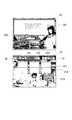
図4は、図2に示した遊技機の内部構成を示すブロック図である。ゲーミングボード50は、内部バスによって互いに接続されたCPU(Central Processing Unit)51と、ROM55及びブートROM52と、メモリカード53に対応したカードスロット53Sと、GAL(Generic Array Logic)54に対応したICソケット54Sとを備えている。 FIG. 4 is a block diagram showing an internal configuration of the gaming machine shown in FIG. The
メモリカード53は、コンパクトフラッシュ(登録商標)等の不揮発性メモリからなり、ゲームプログラム及びゲームシステムプログラムを記憶している。ゲームプログラムには、抽選プログラムが含まれている。上記抽選プログラムは、入賞ライン上に再配置される各リール14のシンボル(シンボルに対応するコードNo.)を決定するためのプログラムである。上記抽選プログラムには、複数種類のペイアウト率(例えば、80%、84%、88%)のそれぞれに対応したシンボル重み付けデータが含まれている。シンボル重み付けデータは、3つのリール14のそれぞれについて、各シンボルのコードNo.(図3参照)と、所定の数値範囲(0〜256)に属する1又は複数の乱数値との対応関係を示すデータである。ペイアウト率は、GAL54から出力されるペイアウト率設定用データに基づいて定められるものであり、このペイアウト率に対応したシンボル重み付けデータに基づいて抽選が行われる。 The
また、カードスロット53Sは、メモリカード53を挿抜可能なように構成されていて、IDEバスによってマザーボード40に接続されている。したがって、カードスロット53Sからメモリカード53を抜き取り、メモリカード53に別のゲームプログラム及びゲームシステムプログラムを書き込み、そのメモリカード53をカードスロット53Sに差し込むことにより、遊技機10で行われる遊技の種類や内容を変更することができる。また、一のゲームプログラム及びゲームシステムプログラムを記憶したメモリカード53を、別のゲームプログラム及びゲームシステムプログラムを記憶したメモリカード53に交換することによって、遊技機10で行われる遊技の種類や内容を変更することも可能である。ゲームプログラムには、遊技進行に係るプログラム、ボーナスゲームを発生させるためのプログラム、還元モードを発生させるためのプログラムが含まれる。また、ゲームプログラムには、遊技中に出力される画像データや音データ、保険有モードに移行していることを報知するための報知用データとしての画像データや音データが含まれる。 The
GAL54は、OR固定型アレイ構造を有するPLDの一種である。GAL54は、複数の入力ポートと出力ポートとを備えていて、入力ポートに所定のデータが入力されると、該データに対応したデータを出力ポートから出力する。この出力ポートから出力されたデータが、上述したペイアウト率設定用データである。また、ICソケット54Sは、GAL54を着脱可能なように構成されていて、PCIバスによってマザーボード40に接続されている。したがって、ICソケット54SからGAL54を抜き取り、GAL54に格納されるプログラムを書き換えて、そのGAL54をICソケット54Sに取り付けることにより、GAL54から出力されるペイアウト率設定用データを変更することができる。また、GAL54を、別のGAL54に交換することによって、ペイアウト率設定用データを変更することも可能である。 The
内部バスによって互いに接続されたCPU51、ROM55及びブートROM52は、PCIバスによってマザーボード40に接続されている。PCIバスは、マザーボード40とゲーミングボード50との間の信号伝達を行うとともに、マザーボード40からゲーミングボード50への電力供給を行う。ROM55には、国識別情報及び認証プログラムが記憶される。ブートROM52には、予備認証プログラム及びCPU51が予備認証プログラムを起動するためのプログラム(ブートコード)等が記憶されている。 The
認証プログラムは、ゲームプログラム及びゲームシステムプログラムを認証するためのプログラム(改竄チェックプログラム)である。認証プログラムは、認証取込処理の対象となるゲームプログラム及びゲームシステムプログラムが改竄されていないことの確認及び証明、すなわち、ゲームプログラム及びゲームシステムプログラムの認証を行う手順(認証手順)に沿って記述されている。予備認証プログラムは、上述した認証プログラムを認証するためのプログラムである。予備認証プログラムは、認証処理の対象となる認証プログラムが改竄されていないことの証明、すなわち、認証プログラムの認証を行う手順(認証手順)に沿って記述されている。 The authentication program is a program (tamper check program) for authenticating the game program and the game system program. The authentication program is described in accordance with a procedure (authentication procedure) for verifying and verifying that the game program and game system program to be authenticated are not falsified, that is, authenticating the game program and game system program. Has been. The preliminary authentication program is a program for authenticating the above-described authentication program. The preliminary authentication program is described in accordance with a proof that the authentication program to be authenticated has not been falsified, that is, a procedure for authenticating the authentication program (authentication procedure).
マザーボード40は、市販の汎用マザーボード(パーソナルコンピュータの基本部品を実装したプリント配線板)を用いて構成され、メインCPU41と、ROM(Read Only Memory)42と、RAM(Random Access Memory)43とを備えている。メインCPU41は、本発明における演算処理装置である。 The
ROM42には、フラッシュメモリ等のメモリデバイスからなり、メインCPU41により実行されるBIOS(Basic Input/Output System)等のプログラムと、恒久的なデータが記憶されている。メインCPU41によってBIOSが実行されると、所定の周辺装置の初期化処理が行われるとともに、メモリカード53に記憶されているゲームプログラム及びゲームシステムプログラムのゲーミングボード50を介した取込処理が開始される。なお、本発明において、ROM42は、内容の書き換えが可能なものであってもよく、不可能なものであってもよい。 The
RAM43には、メインCPU41が作動する際に用いられるデータやプログラムが記憶される。また、RAM43は、ゲーミングボード50を介して読み出される認証プログラムと、ゲームプログラム及びゲームシステムプログラムとを記憶することができる。RAM43は、本発明における記憶装置である。 The
また、RAM43には、保険モードフラグの記憶領域が設けられている。保険モードフラグは、保険有モードであるか保険無モードであるかを示すフラグである。保険モードフラグの記憶領域は、例えば、所定ビット数の記憶領域からなり、該記憶領域における記憶内容に応じて保険モードフラグが“ON”又は“OFF”となる。保険モードフラグ“ON”は、保険有モードを示し、保険モードフラグ“OFF”は、保険無モードを示す。更に、RAM43には、クレジット数や、1回の遊技における投入数や払出数等のデータが記憶される。ゲーム回数をカウントするゲーム回数カウンタの記憶領域も設けられている。 The
また、マザーボード40には、後述する本体PCB(Printed Circuit Board)60及びサブPCB80とが、それぞれUSBによって接続されている。更に、マザーボード40には、電源ユニット45が接続されている。電源ユニット45からマザーボード40に電力が供給されると、マザーボード40のメインCPU41が起動するとともに、PCIバスを介してゲーミングボード50に電力が供給されてCPU51が起動される。 Further, a main body PCB (Printed Circuit Board) 60 and a
本体PCB60及びサブPCB80には、メインCPU41に入力される入力信号を発生させる機器や装置と、メインCPU41から出力される制御信号により動作が制御される機器や装置とが接続されている。メインCPU41は、メインCPU41に入力された入力信号に基づいて、RAM43に記憶されたゲームプログラム及びゲームシステムプログラムを実行することにより、所定の演算処理を行ってその結果をRAM43に記憶したり、各機器や装置に対する制御処理として各機器や装置に制御信号を送信したりする。 The
本体PCB60には、ランプ30、サブCPU61、ホッパー66、コイン検出部67、グラフィックボード68、出力装置としてのスピーカ29、タッチパネル69、紙幣識別器22、カードリーダ36、キースイッチ38S及びデータ表示器37が接続されている。ランプ30は、メインCPU41から出力される制御信号に基づいて、所定のパターンで点灯する。 The
サブCPU61は、リール14(14L、14C、14R)の回転及び停止の制御を行うものである。サブCPU61には、FPGA(Field Programmable Gate Array)63及びドライバ64を備えたモータ駆動回路62が接続されている。FPGA63は、プログラミング可能なLSI等の電子回路であり、ステッピングモータ70の制御回路として機能するものである。ドライバ64は、ステッピングモータ70に入力するパルスの増幅回路として機能するものである。モータ駆動回路62には、各リール14の回転を行うステッピングモータ70(70L、70C、70R)が接続されている。ステッピングモータ70は、1−2相励磁方式のステッピングモータである。 The
本発明において、ステッピングモータの励磁方式は、特に限定されるものではなく、例えば、2相励磁方式、1相励磁方式等を採用することも可能である。また、ステッピングモータにかえて、DCモータを採用することとしてもよい。DCモータが採用される場合、サブCPU61には、偏差カウンタ、D/A変換器、サーボ増幅器が順に接続され、サーボ増幅器にDCモータが接続されることになる。また、DCモータの回転位置は、ロータリエンコーダによって検出され、ロータリエンコーダから偏差カウンタに対してDCモータの現在の回転位置がデータとして供給される。 In the present invention, the excitation method of the stepping motor is not particularly limited, and for example, a two-phase excitation method, a one-phase excitation method, or the like can be adopted. Moreover, it is good also as employ | adopting a DC motor instead of a stepping motor. When a DC motor is employed, a deviation counter, a D / A converter, and a servo amplifier are sequentially connected to the
また、サブCPU61には、インデックス検出回路65と、位置変更検出回路71とが接続されている。インデックス検出回路65は、回転中のリール14の位置(後述するインデックス)を検出するものであり、更に、リール14の脱調を検出可能である。なお、リール14の回転及び停止の制御については、後で図面を用いて詳述することにする。 Further, an
位置変更検出回路71は、リール14の回転が停止した後におけるリール14の停止位置の変更を検出する。例えば、位置変更検出回路71は、実際には入賞態様となるシンボルの組合せではないにも関わらず、プレイヤにより強制的に入賞態様となるシンボルの組合せになるように停止位置が変更された場合等に係るリール14の停止位置の変更を検出する。位置変更検出回路71は、例えば、リール14の内側部分に所定間隔で取り付けられたフィン(図示せず)を検出することにより、リール14の停止位置の変更を検出可能に構成されている。 The position change detection circuit 71 detects a change in the stop position of the
ホッパー66は、キャビネット11内に設置されていて、メインCPU41から出力される制御信号に基づいて、所定数のコインをコイン払出口19からコイントレイ18に払い出す。コイン検出部67は、コイン払出口19の内部に設けられていて、コイン払出口19から所定枚数のコインが払い出されたことを検出した場合には、メインCPU41に対して入力信号を出力する。 The
グラフィックボード68は、メインCPU41から出力される制御信号に基づいて、出力装置としての上側画像表示パネル33及び下側画像表示パネル16における画像表示を制御する。下側画像表示パネル16のクレジット数表示部31には、RAM43に記憶されているクレジット数が表示される。また、下側画像表示パネル16のペイアウト数表示部32には、コインの払出数が表示される。グラフィックボード68は、メインCPU41から出力される制御信号に基づいて画像データを生成するVDP(Video Display Processor)や、VDPによって生成される画像データを一時的に記憶するビデオRAM等を備えている。なお、VDPによって画像データを生成する際に用いられる画像データは、メモリカード53から読み出されてRAM43に記憶されたゲームプログラム内に含まれている。 The
紙幣識別器22は、紙幣の適否を識別するとともに正規の紙幣をキャビネット11内に受け入れる。紙幣識別器22は、正規の紙幣を受け入れたとき、その紙幣の額に基づいてメインCPU41に対して入力信号を出力する。メインCPU41は、該入力信号により伝達された紙幣の額に応じたクレジット数をRAM43に記憶する。 The bill validator 22 recognizes whether or not a bill is appropriate and accepts a regular bill into the
カードリーダ36は、スマートカードからのデータを読み取ってメインCPU41へ送信したり、メインCPU41からの制御信号に基づいてスマートカードへのデータの書き込みを行ったりする。キースイッチ38Sは、キーパッド38に設けられていて、キーパッド38がプレイヤによって操作されたとき、所定の入力信号をメインCPU41へ出力する。データ表示器37は、メインCPU41から出力される制御信号に基づいて、カードリーダ36が読み取ったデータやプレイヤによってキーパッド38を介して入力されたデータを表示する。 The
サブPCB80には、コントロールパネル20、リバータ21S、コインカウンタ21C及び冷陰極管81が接続されている。コントロールパネル20には、スピンボタン23に対応したスピンスイッチ23S、チェンジボタン24に対応したチェンジスイッチ24S、CASHOUTボタン25に対応したCASHOUTスイッチ25S、1−BETボタン26に対応した1−BETスイッチ26S、及び、最大BETボタン27に対応した最大BETスイッチ27Sが設けられている。各スイッチ23S〜27Sは、対応するボタン23〜27がプレイヤによって操作されたとき、メインCPU41に対して入力信号を出力する。 A
コインカウンタ21Cは、コイン受入口21の内部に設けられていて、プレイヤによってコイン受入口21に投入されたコインの適否を識別する。正規のコイン以外のものは、コイン払出口19から排出される。また、コインカウンタ21Cは、正規のコインを検出したときにメインCPU41に対して入力信号を出力する。 The
リバータ21Sは、メインCPU41から出力される制御信号に基づいて動作するものであり、コインカウンタ21Cによって正規のコインとして認識されたコインを、遊技機10内に設置されたキャッシュボックス(図示せず)又はホッパー66に振り分ける。すなわち、ホッパー66がコインで満たされている場合、正規のコインはリバータ21Sによってキャッシュボックスに振り分けられる。一方、ホッパー66がコインで満たされていない場合には、正規のコインはホッパー66に振り分けられる。冷陰極管81は、下側画像表示パネル16と、上側画像表示パネル33との背面側に設置されるバックライトとして機能するものであり、メインCPU41から出力される制御信号に基づいて点灯する。 The
次に、遊技機10において行われる処理について説明する。図5は、図4に示したマザーボード40とゲーミングボード50とによるゲームプログラム及びゲームシステムプログラムの認証読取処理の手順を示したチャートである。なお、ゲーミングボード50におけるカードスロット53Sには、メモリカード53が差し込まれ、ICソケット54Sには、GAL54が取り付けられているものとする。 Next, processing performed in the
まず、電源ユニット45において電源スイッチの投入(電源の投入)が行われると、マザーボード40及びゲーミングボード50を起動する(ステップS1−1、S2−1)。マザーボード40及びゲーミングボード50が起動すると、それぞれ別個の処理が並行して行われる。すなわち、ゲーミングボード50では、CPU51が、ブートROM52に格納されている予備認証プログラムの読み出しを行い、その読み出した予備認証プログラムに従い、マザーボード40への取込前に予め認証プログラムの改竄が行われていないことを確認及び証明する予備認証を行う(ステップS2−2)。一方、マザーボード40では、メインCPU41が、ROM42に格納されているBIOSを実行して、BIOSに組み込まれている圧縮データをRAM43に展開する(ステップS1−2)。そして、メインCPU41は、RAM43に展開されたBIOSを実行し、各種周辺装置の診断と初期化とを行う(ステップS1−3)。 First, when the power switch is turned on (power is turned on) in the
すると、メインCPU41には、PCIバスを介して、ゲーミングボード50のROM55が接続されているので、メインCPU41は、ROM55に格納されている認証プログラムの読み出しを行うとともに、読み出した認証プログラムをRAM43に記憶させる処理を行う(ステップS1−4)。このとき、メインCPU41は、BIOSの標準BIOSの機能に従い、ADDSUM方式(標準チェック機能)によるチェックサムを取り、格納が間違いなく行われるか否かの確認処理を行いながら、認証プログラムをRAM43に記憶させる。 Then, since the
次に、メインCPU41は、IDEバスに何が接続されているのかを確認した上で、IDEバスを介してカードスロット53Sに差し込まれているメモリカード53にアクセスし、メモリカード53から、ゲームプログラム及びゲームシステムプログラムの読み出しを行う。この場合、メインCPU41は、ゲームプログラム及びゲームシステムプログラムを構成するデータを4バイトずつ読み出す。続いて、メインCPU41は、RAM43に記憶された認証プログラムに従い、読み出したゲームプログラム及びゲームシステムプログラムの改竄が行われていないことを確認及び証明する認証を行う(ステップS1−5)。この認証処理が正常に終了すると、メインCPU41は、認証対象となった(認証された)ゲームプログラム及びゲームシステムプログラムをRAM43に書き込み記憶させる(ステップS1−6)。次に、メインCPU41は、PCIバスを介してICソケット54Sに取り付けられているGAL54にアクセスし、GAL54から、ペイアウト率設定用データを読み込み、RAM43に書き込み記憶させる(ステップS1−7)。次に、メインCPU41は、PCIバスを介して、ゲーミングボード50のROM55に格納されている国識別情報の読み出しを行うとともに、読み出した国識別情報をRAM43に記憶させる処理を行う(ステップS1−8)。 Next, after confirming what is connected to the IDE bus, the
上述した処理を行った後、メインCPU41は、ゲームプログラム及びゲームシステムプログラムを順次読み出して実行することにより、遊技を進行させる。 After performing the processing described above, the
図5に示した処理が行われた後、メインCPU41は、遊技モード選択処理を行う。図6は、遊技モード選択処理のサブルーチンを示すフローチャートである。なお、メインCPU41は、このサブルーチンを実行している間に、コイン受入口21に投入されたコインがコインカウンタ21Cによって検出された際にコインカウンタ21Cから出力される検出信号を受信したとき、割込処理として、RAM43に記憶されたクレジット数を加算する処理を行う。 After the process shown in FIG. 5 is performed, the
まず、メインCPU41は、RAM43に格納された保険モードフラグが“ON”にセットされているか否かを判断する(ステップS11)。保険モードフラグが“ON”にセットされていない、すなわち、保険モードフラグが“OFF”にセットされていると判断した場合、保険無モード画像を表示する処理を行う(ステップS12)。この処理において、メインCPU41は、保険無モード画像の描画命令をグラフィックボード68に送信する。グラフィックボード68では、上記描画命令に基づいて、VDPが画像データをRAM43から抽出してビデオRAMに展開し、1フレームの画像データを生成し、この画像データを上側画像表示パネル33及び下側画像表示パネル16に出力する。その結果、上側画像表示パネル33及び下側画像表示パネル16には、例えば、図7に示すような画像が表示される。 First, the
図7は、保険無モードにおいて上側画像表示パネル33及び下側画像表示パネル16に表示される画像の一例(上側画像301、下側画像401)を示す図である。下側画像401中、15(15L、15C、15R)は、表示窓を示している。31は、クレジット数表示部を示している。32は、ペイアウト数表示部を示している。PAYLINE214は、入賞ラインを示している。また、下側画像401の右下部には、「BET FOR RESCUE PAY MORE INFO」を示す画像210が表示されている。プレイヤは、画像210の表示領域に対応するタッチパネル69の所定箇所に触れることにより、保険有モードを選択することができる画面へ移行させることができる。 FIG. 7 is a diagram illustrating an example of images (
図8は、保険無モードにおいて保険有モードを選択する場合、下側画像表示パネルに表示される画像の一例を示す図である。画像210の表示領域に対応するタッチパネル69の所定箇所に触れた場合、下側画像表示パネル16に下側画像402が表示される。この下側画像402中の下方部に、保険有モードの選択をプレイヤに要求するための画像220が表示されている。画像220は、還元モードでの所定数のクレジットのペイアウト(レスキューペイ)についての説明とともに、保険有モードを選択するための画像であるYES221と、保険無モードを選択するための画像であるNO222とを表示している。プレイヤは、画像YES221の表示領域に対応するタッチパネル69の所定箇所に触れることにより、保険有モードを選択する旨の指示を入力することができる。 FIG. 8 is a diagram illustrating an example of an image displayed on the lower image display panel when the insurance mode is selected in the non-insurance mode. When a predetermined part of the
保険有モードが選択された場合、その後、単位ゲームで所定以上(本実施形態では180)のクレジットの取得をすることなく、かつ、ボーナスゲームも発生することなくゲーム回数が特定回数(例えば1000)に達すると、遊技機10は、還元モードに移行する。還元モードでは、プレイヤは、所定数(本実施形態では360)に獲得ポイントに応じた倍率を掛けた分のクレジット、又はそれに相当するコインを取得することができる。すなわち、プレイヤは、保険有モードでは、長時間にわたってクレジットの取得やボーナスゲームの発生がなかった場合に生じる損失の全部又は一部を補填するための保険を掛けた状態で、遊技を行うことができる。 When the insurance mode is selected, after that, the number of games is a specific number of times (for example, 1000) without acquiring a predetermined or more credit (180 in this embodiment) in the unit game and without generating a bonus game. When reaching, the
一方、保険有モードを選択する旨の指示が入力されなかった場合には、保険無モードが選択される。保険無モードが選択された場合、その後、長期間にわたってボーナスゲームが発生しなかったとしても、遊技機10が、還元モードに移行することもない。 On the other hand, when the instruction to select the insurance mode is not input, the non-insurance mode is selected. When the non-insurance mode is selected, the
ステップS12の処理の後、メインCPU41は、ヘルプ画像を表示する旨の指示が入力されたか否かを判断する(ステップS13)。ヘルプ画像を表示する旨の指示は、タッチパネル69の所定箇所がプレイヤによって触れられたときに入力される。 After the process of step S12, the
ヘルプ画像を表示する旨の指示が入力された場合には、ヘルプ画像を表示する処理を行う(ステップS14)。この処理において、メインCPU41は、ヘルプ画像の描画命令をグラフィックボード68に送信する。グラフィックボード68は、上記描画命令に基づいて、上側画像表示パネル33及び下側画像表示パネル16に画像を表示する処理を行う。 When an instruction to display a help image is input, processing for displaying a help image is performed (step S14). In this process, the
ステップS14の処理を実行した場合、又は、ステップS13において、ヘルプ画像を表示する旨の指示が入力されなかった場合、メインCPU41は、保険有モードを選択する旨の指示が入力されたか否かを判断する(ステップS15)。保険有モードを選択する旨の指示は、上述したように、画像220中のYES221の表示領域に対応するタッチパネル69の所定箇所がプレイヤによって触れられたときに入力される。 When the process of step S14 is executed, or when an instruction to display the help image is not input in step S13, the
保険有モードを選択する旨の指示が入力されたときには、メインCPU41は、RAM43に格納された保険モードフラグを“ON”にセットする(ステップS16)。続いて、メインCPU41は、RAM43に記憶されたクレジット数から、所定数を減算する処理を行う(ステップS17)。 When an instruction to select the insurance mode is input, the
ステップS11において、保険モードフラグが“ON”にセットされていると判断した場合、又は、ステップS17の処理を実行した場合、保険有モード画像を表示する処理を行う(ステップS18)。この処理において、メインCPU41(演算処理装置)は、保険有モード画像の描画命令をグラフィックボード68に送信する。グラフィックボード68では、上記描画命令に基づいて、VDPが、報知用データとしての画像データをRAM43(記憶装置)から抽出してビデオRAMに展開し、1フレームの画像データを生成し、この画像データを上側画像表示パネル33及び下側画像表示パネル16に出力する。その結果、上側画像表示パネル33及び下側画像表示パネル16には、例えば、図9に示すような画像が表示される。 When it is determined in step S11 that the insurance mode flag is set to “ON”, or when the process of step S17 is executed, a process for displaying the insurance mode image is performed (step S18). In this process, the main CPU 41 (arithmetic processing unit) transmits an insurance mode image drawing command to the
図9は、保険有モードにおいて上側画像表示パネル33及び下側画像表示パネル16に表示される画像の一例を示す図である。図9の(1)は、図8において、プレイヤがYES221を選択しことに応じて移行した保険有モードにおいて、上側画像表示パネル33及び下側画像表示パネル16に表示される画像の一例(上側画像302、下側画像403)を示す図である。上側画像302は、保険有モードなので「RESCUE ON」の画像230を表示している。下側画像403の右下部には、保険有モードを示す「RESCUE ON MORE INFO」の画像235が表示され、保険有モード中に還元モードになる条件等を示す「MAXBETで1000ゲーム当選しなかった場合レスキューペイとして360クレジットペイアウトします。」の画像236が表示されている。ここで、MAXBETとは、最大BET数のことをいい、1回の遊技に賭けることが可能な最大枚数をいう。 FIG. 9 is a diagram illustrating an example of images displayed on the upper
図9の(2)は、保険有モード中にプレイヤが単位ゲームを実行した場合、下側画像表示パネル16に表示される画像の一例(下側画像404)を示す図である。下側画像404は、還元モードになるための(レスキューペイされるまでの)残りゲーム数について、例えば、「MAXBETで999ゲーム当選しなかった場合レスキューペイとして360クレジットペイアウトします。」の画像237を表示している。 (2) of FIG. 9 is a diagram illustrating an example of an image (lower image 404) displayed on the lower
ステップS18の処理の後、メインCPU41は、保険有モード時における遊技実行処理を行う(ステップS19)。この処理については後で図10を用いて詳述するが、保険有モードでは、上側画像表示パネル33に上側画像302が表示され、下側画像表示パネル16に下側画像403が表示される。 After the process of step S18, the
一方、ステップS15において、保険有モードを選択する旨の指示が入力されなかった場合、メインCPU41は、保険無モード時における遊技実行処理を行う(ステップS20)。この処理は、還元モード移行に係る処理と、ゲーム回数の計数に係る処理とが行われないことを除いて、保険有モード時における遊技実行処理(図10参照)と略同様の処理であるから、ここでの説明は省略する。ステップS19又はS20の処理を実行した場合には、その後、ステップS11に処理を戻す。 On the other hand, if an instruction to select the insurance mode is not input in step S15, the
本実施形態では、報知用データに基づいて、出力装置としての上側画像表示パネル33及び下側画像表示パネル16に、保険有モードに移行したことを報知するための上側画像302、下側画像403が表示される場合について説明したが、本発明においては、報知用データに基づいて、出力装置としてのスピーカ29から、保険有モードに移行したことを報知するための音を出力することとしてもよい。 In the present embodiment, based on the notification data, the
図10は、図6に示したサブルーチンのステップS19において呼び出されて実行される保険有モード時の遊技実行処理のサブルーチンを示すフローチャートである。フローチャート上、ゲーム回数カウンタがカウントとする値をGとする。 FIG. 10 is a flowchart showing a subroutine of game execution processing in the insurance mode that is called and executed in step S19 of the subroutine shown in FIG. In the flowchart, G is a value counted by the game number counter.
遊技実行処理においては、まず、メインCPU41は、コインがBETされたか否かを判断する(ステップS21)。この処理において、メインCPU41は、1−BETボタン26が操作された際に1−BETスイッチ26Sから出力される入力信号、又は、最大BETボタン27が操作された際に最大BETスイッチ27Sから出力される入力信号を受信したか否かを判断する。コインがBETされていないと判断した場合、ステップS21に処理を戻す。 In the game execution process, first, the
一方、ステップS21において、コインがBETされたと判断した場合、メインCPU41は、BETされたコインの枚数に応じて、RAM43に記憶されたクレジット数を減算する処理を行う(ステップS22)。 On the other hand, if it is determined in step S21 that a coin has been betted, the
次に、メインCPU41は、スピンボタン23がONされたか否かを判断する(ステップS23)。この処理において、メインCPU41は、スピンボタン23が押下された際にスピンスイッチ23Sから出力される入力信号を受信したか否かを判断する。スピンボタン23がONされていないと判断した場合、ステップS23に処理を戻す。なお、スピンボタン23がONされなかった場合(例えば、スピンボタン23がONされずに遊技を終了する旨の指示が入力された場合)には、メインCPU41は、ステップS22における減算結果をキャンセルする。 Next, the
次に、メインCPU41は、MAXBETか否かを判断する(ステップS24)。この処理において、メインCPU41は、BETした値が最大BET数か否かを判断する。MAXBETであると判断した場合、ゲーム回数(G)をカウントする(ステップS25)。ここで、ゲーム回数(G)の値は、保険有モードに移行したときにクリアする(G=0)。 Next, the
ステップS25の処理を実行した場合、又は、ステップS24において、MAXBETでないと判断した場合、メインCPU41は、停止シンボル決定処理を行う(ステップS26)。この停止シンボル決定処理において、メインCPU41(演算処理装置)は、RAM43(記憶装置)に記憶された抽選プログラムを実行することにより、各リール14の停止時におけるコードNo.を決定する。これにより、再配置されるシンボルの組合せが決定される。この処理については、後で図14及び図15を用いて詳述することにする。なお、本実施形態では、再配置されるシンボルの組合せを決定することにより、複数種類の役の中から1つの役を決定する場合について説明するが、本発明においては、例えば、まず、抽選によって、複数種類の役の中から選ばれる1つの役を決定し、その後に、再配置されるシンボルの組合せを上記役に基づいて決定することとしてもよい。 When the process of step S25 is executed, or when it is determined in step S24 that it is not MAXBET, the
次に、メインCPU41は、リールの回転制御処理を行う(ステップS27)。この処理は、全リール14の回転を開始した後、ステップS26において決定された役に対応したシンボルの組合せが入賞ライン上に再配置されるように、各リールの回転を停止させる処理である。この処理については、後で図17〜図19を用いて詳述することにする。次に、メインCPU41は、ポイント加算処理を行う(ステップS28)。この処理については、後で図11用いて詳述することにする。次に、メインCPU41は、役判定処理を行う(ステップS29)。この処理については、後で図14及び図15用いて詳述することにする。次に、メインCPU41は、計数処理を行う(ステップS30)。この処理については、後で図17を用いて詳述することにする。 Next, the
図11は、図10に示したサブルーチンのステップS28において呼び出されて実行されるポイント加算処理のサブルーチンを示すフローチャートである。なお、このポイント加算処理は、保険有モード時のみならず、保険無モードにおいても実行されるようにしてもよい。 FIG. 11 is a flowchart showing a subroutine of point addition processing called and executed in step S28 of the subroutine shown in FIG. The point addition process may be executed not only in the insurance mode but also in the non-insurance mode.
まず、メインCPU41は、ポイント付与シンボルが成立したか否か、すなわち、入賞ライン上に左から順に「7」「7」「DORA」が再配置されたか否かを判断する(ステップS31)。この判断がYESの場合には、処理をステップS32に移し、NOの場合には、メインCPU41は、本サブルーチンを終了する。 First, the
ステップS32では、ポイント加算処理を行う。この処理では、RAM43の所定の領域に格納されたポイントカウンタに1を加算する処理を行う。この処理が終了すると、メインCPU41は、本サブルーチンを終了する。 In step S32, point addition processing is performed. In this process, 1 is added to the point counter stored in a predetermined area of the
図12を参照して、倍率テーブルについて説明する。この倍率テーブルは、後述の図16のステップS63及び図24のステップS122において、クレジットの払出数を決定する際にメインCPU41が参照するテーブルである。例えば、ポイント(ポイントカウンタの値)が1〜4の場合には、倍率は「1.5」と決定される。 The magnification table will be described with reference to FIG. This magnification table is a table that the
図13は、ポイントを獲得した上側画像表示パネル33に表示される画像の一例を示す図である。この図が示す画像は、獲得しているポイントと、払出す場合の倍率とを表している。獲得しているポイントは、斜線マーク102で表し、払出す場合の倍率は、「×1.5」、「×2」、「×4」及び「×8」の表示で、それぞれ表している。また、倍率が上がる(例えば、1.5倍から2倍になる)ために必要なポイントは、白丸103で表している。例えば、この図が示す画像では、ポイントが1〜4では1.5倍、ポイントが5〜9では2倍、ポイントが10〜14では4倍、15以上では8倍であることを表している。メッセージ「POINT GET!」101はポイントを獲得したことを表している。 FIG. 13 is a diagram illustrating an example of an image displayed on the upper
図14は、図10に示したサブルーチンのステップS29において呼び出されて実行される役判定処理のサブルーチンの1つの例である役判定処理1のサブルーチンを示すフローチャートである。 FIG. 14 is a flowchart showing a subroutine of
まず、メインCPU41は、ボーナスゲームトリガーが成立したか否か、すなわち、表示窓15内に「7」が再配置されたか否かを判断する(ステップS41)。ボーナスゲームトリガーが成立したと判断した場合には、メインCPU41(演算処理装置)は、ボーナスゲームを行うためのプログラムをRAM43(記憶装置)から読み出してボーナスゲーム処理を実行する(ステップS42)。ボーナスゲーム処理については、後で図25を用いて詳述することにする。 First, the
ステップS42の処理の後、ゲーム回数カウンタを0にする(ステップS43)。なお、本実施例では、ゲーム回数カウンタを0にしたが、保険有モードから保険無モードへ移行する(保険モードフラグをOFFにする)としてもよい。ボーナスゲームへ移行することに応じて、保険無モードに戻ることにより、遊技で利益を得ているプレイヤとの公平感を保つことができる。 After the process of step S42, the game number counter is set to 0 (step S43). In this embodiment, the game number counter is set to 0. However, the insurance mode may be switched to the non-insurance mode (the insurance mode flag is turned OFF). By returning to the non-insurance mode in accordance with the transition to the bonus game, it is possible to maintain a sense of fairness with the player who is profitable from the game.
一方、ステップS41において、ボーナスゲームトリガーが成立していないと判断した場合、メインCPU41は、役が成立したか否かを判断する(ステップS44)。役が成立したと判断した場合、メインCPU41は、ペイアウト処理(投入数及び役に応じたコインの払い出し)を行う(ステップS45)。コインの貯留を行う場合、メインCPU41は、RAM43に記憶されたクレジット数を加算する処理を行う。一方、コインの払い出しを行う場合には、メインCPU41は、ホッパー66に制御信号を送信して所定数のコインの払い出しを行う。その際、コイン検出部67は、ホッパー66から払い出されるコインの枚数を計数し、その計数値が指定された数に達したときに、払出完了信号をメインCPU41に送信する。これにより、メインCPU41は、ホッパー66の駆動を停止し、コインの払出処理を終了する。 On the other hand, if it is determined in step S41 that the bonus game trigger has not been established, the
ステップS43若しくはステップS45の処理を実行した場合、又は、ステップS44において、いずれの役も成立していないと判断した場合(ハズレであると判断した場合)、メインCPU41は、本サブルーチンを終了する。 When the process of step S43 or step S45 is executed, or when it is determined in step S44 that no combination is established (when it is determined that the game is lost), the
図15は、図10に示したサブルーチンのステップS29において呼び出されて実行される役判定処理のサブルーチンの他の例である役判定処理2のサブルーチンを示すフローチャートである。役判定処理1では、ボーナスゲーム処理の後にゲーム回数カウンタを0(又は保険モードフラグをOFF)としたが、ペイアウトが予め定められた所定数以上である場合にゲーム回数を0(又は保険モードフラグをOFF)にする処理を行う。フローチャート上、予め定められた所定数をPで表す。 FIG. 15 is a flowchart showing a subroutine of the
まず、メインCPU41は、ボーナスゲームトリガーが成立したか否か、すなわち、表示窓15内に「7」が再配置されたか否かを判断する(ステップS51)。ボーナスゲームトリガーが成立したと判断した場合には、メインCPU41(演算処理装置)は、ボーナスゲームを行うためのプログラムをRAM43(記憶装置)から読み出してボーナスゲーム処理を実行する(ステップS52)。ボーナスゲーム処理については、後で図25を用いて詳述することにする。 First, the
一方、ステップS51において、ボーナスゲームトリガーが成立していないと判断した場合、メインCPU41は、役が成立したか否かを判断する(ステップS54)。役が成立したと判断した場合、メインCPU41は、ペイアウト処理(投入数及び役に応じたコインの払い出し)を行う(ステップS55)。コインの貯留を行う場合、メインCPU41は、RAM43に記憶されたクレジット数を加算する処理を行う。一方、コインの払い出しを行う場合には、メインCPU41は、ホッパー66に制御信号を送信して所定数のコインの払い出しを行う。その際、コイン検出部67は、ホッパー66から払い出されるコインの枚数を計数し、その計数値が指定された数に達したときに、払出完了信号をメインCPU41に送信する。これにより、メインCPU41は、ホッパー66の駆動を停止し、コインの払出処理を終了する。 On the other hand, if it is determined in step S51 that the bonus game trigger has not been established, the
ステップS52若しくはS55の処理を実行した場合、又は、ステップS54において、いずれの役も成立していないと判断した場合(ハズレであると判断した場合)、ペイアウトはP以上か否かを判断する(ステップS53)。この処理において、Pは予め定められた所定のペイアウト数(本実施形態では180クレジット)を表す。ペイアウトはP以上であると判断した場合、メインCPU41は、ゲーム回数カウンタを0にする。なお、本実施例では、ゲーム回数カウンタを0にしたが、保険有モードから保険無モードへ移行する(保険有モードをOFFにする)としてもよい。ボーナスゲームへ移行することに応じて、保険無モードに戻ることにより、遊技で利益を得ているプレイヤとの公平感を保つことができる。 When the process of step S52 or S55 is executed, or when it is determined in step S54 that no combination is established (when it is determined that the game is lost), it is determined whether or not the payout is equal to or greater than P ( Step S53). In this process, P represents a predetermined predetermined payout number (180 credits in the present embodiment). When determining that the payout is P or more, the
ステップS53において、ペイアウトはP以上ではないと判断した場合、又はステップS56の処理を実行した場合、メインCPU41は、本サブルーチンを終了する。 If it is determined in step S53 that the payout is not equal to or greater than P, or if the process of step S56 is executed, the
図16は、図14に示したサブルーチンのステップS45において呼び出されて実行されるペイアウト処理のサブルーチンを示すフローチャートである。 FIG. 16 is a flowchart showing a subroutine of payout processing that is called and executed in step S45 of the subroutine shown in FIG.
まず、メインCPU41は、倍率乗算対象シンボル決定処理を行う(ステップS61)。この処理において、メインCPU41は、払出しの際に倍率を掛ける対象となるシンボルの組合せ(例えば、「PLUM、PLUM、PLUM」)を決定する。次に、メインCPU41は、処理をステップS62に移す。 First, the
ステップS62において、メインCPU41は、入賞は、倍率乗算対象シンボルか否かを判断する。倍率乗算対象シンボルであると判断した場合、メインCPU41は、図12で示した倍率テーブルを参照して、ポイントカウンタに応じた倍率を取得する(ステップS63)。次に、ステップS65へ処理を移す。 In step S62, the
一方、ステップS62において、倍率乗算対象シンボルではないと判断した場合、メインCPU41は、倍率を1にする(ステップS64)。次に、ステップS65へ処理を移す。 On the other hand, when determining in step S62 that the symbol is not a multiplication target symbol, the
ステップS65において、メインCPU41は、入賞シンボルの配当に倍率を掛けた払出しを行う。具体的には、ステップS63の処理で取得した倍率又は、ステップS64で取得した倍率である1に、ステップS61の処理で決定したシンボルの組合せ(例えば、「PLUM、PLUM、PLUM」)に応じた払出数を掛けて、掛けた値のクレジットを払出す。ここで、シンボルの組合せに応じた払出数は、図20に示すテーブルに格納されている。 In step S65, the
図17は、図10に示したサブルーチンのステップS30において呼び出されて実行される計数処理のサブルーチンを示すフローチャートである。フローチャート上、ゲーム回数カウンタがカウントとした値をGで、保険有モードへ移行するゲーム回数である特定回数をXで表す。 FIG. 17 is a flowchart showing a counting process subroutine called and executed in step S30 of the subroutine shown in FIG. In the flowchart, the value counted by the game number counter is represented by G, and the specific number of games that are shifted to the insurance mode is represented by X.
まず、メインCPU41は、GがX−10の値以上であるか否かを判断する(ステップS71)。すなわち、メインCPU41は、ゲーム回数カウンタの値(G)が、保険有モードへ移行するゲーム回数である特定回数(X)まで、残り10以下であるか否かを判断する。残りゲーム数が10以下であると判断した場合、保険予告演出表示処理を行う(ステップS72)。保険予告演出表示処理は、図18を用いて詳述するように、還元モードへの移行が近いので残りゲーム数を大きく表示する等の演出表示(図26から図30)を行う。 First, the
次に、メインCPU41は、GがXと等しいか否かを判断する(ステップS73)。すなわち、メインCPU41は、ゲーム回数カウンタ(G)と特定回数(X)とが等しいか否かを判断し、等しいと判断した場合、還元モードとなり、保険発生演出表示を行う(ステップS74)。この処理は、図31から図32で示される画像を表示する。 Next, the
次に、メインCPU41は、停止シンボル決定処理を行う(ステップS75)。メインCPU41は、図19で詳述する停止シンボル決定処理を呼び出し、還元モードになった場合に行う抽選を行い、再配置するシンボルの組合せを決定する。 Next, the
次に、メインCPU41は、図21で詳述するリール回転制御処理を呼び出し、抽選結果に基づいたシンボルの組合せのリール回転制御処理を行う(ステップS76)。次に、メインCPU41は、図14又は図15で詳述した役判定処理を呼び出し、回転表示したシンボルの組合せについて、役の判定を行う(ステップS77)。 Next, the
次に、メインCPU41は、図24で詳述する保険払出処理を行う(ステップS78)。次に、メインCPU41は、保険モードフラグをOFFにする(ステップS79)。その後、メインCPU41は、本サブルーチンを終了する。 Next, the
図18は、図17に示したサブルーチンのステップS72において呼び出されて実行される保険予告演出表示処理のサブルーチンを示すフローチャートである。 FIG. 18 is a flowchart showing a subroutine of insurance notice effect display processing that is called and executed in step S72 of the subroutine shown in FIG.
まず、メインCPU41は、このゲームはMAXBETだったか否かを判断する(ステップS81)。具体的には、メインCPU41は、図10のステップS24の判断がMAXBETだったか否かを判断する。MAXBETだったと判断した場合、メインCPU41は、特定回数(X)からゲーム回数のカウント値(G)を減算した、特定回数とゲーム回数との差を表示する(ステップS82)。 First, the
ステップS82の処理を実行した場合、又は、ステップS81において、MAXBETではなかったと判断した場合、メインCPU41は、演出画像表示を行う(ステップS83)。この処理では、特定回数からゲーム回数のカウント値を減算した値が10以下の場合なので、還元モード(所定数のクレジットのペイアウトであるレスキューペイを行う)までの残りゲーム数(10から1)を大きく表示し、図26から図32で示すような特別な演出を行う。 When the process of step S82 is executed, or when it is determined in step S81 that it is not MAXBET, the
図26から図32を参照して、レスキューペイを行うまでの演出画像について説明する。 With reference to FIGS. 26 to 32, the effect image until the rescue pay is performed will be described.
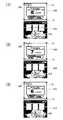
図26は、保険有モードにおいて上側画像表示パネル及び下側画像表示パネルに表示される画像の一例を示す図である。図26の(1)は、保険有モードにおいて上側画像表示パネル33及び下側画像表示パネル16に表示される画像の一例(上側画像306、下側画像406)を示す図である。上側画像306中、中央部の画像240は、レスキューペイまでの残りゲーム数である10ゲームを「MAXBETした場合にレスキューペイまでの残りゲーム数」という説明文とともに、「10GAMES」の画像240を表示している。さらに、上側画像306中、左上部には、獲得したポイント(ポイントカウンタの値)を示すポイント表示部280が示されている。この図によれば、獲得ポイントが「2」であることを示している。また、上側画像306中、下方部の画像238は、レスキューオン中であることを「RESCUE ON RESCUE PAY 360CREDITS」と表示している。下側画像406中、下方部の画像242は、レスキューペイまでの残りゲーム数である10ゲームを「10GAMES」と表示している。 FIG. 26 is a diagram illustrating an example of images displayed on the upper image display panel and the lower image display panel in the insurance mode. (1) in FIG. 26 is a diagram illustrating an example of images (
図26の(2)は、図26の(1)の状態で単位ゲームが実行され、ゲーム回数がカウントされた結果、残りゲーム数が1減少し9ゲームになった場合の画像を示す図である。図の画像は、上側画像表示パネル33及び下側画像表示パネル16に表示される画像の一例(上側画像307、下側画像407)である。上側画像307及び下側画像407は、ともに残りゲーム数9を表示している。また、上側画像307中のポイント表示部280は、獲得ポイントが「2」であることを示している。また、下側画像407中の下方部に、光245が表示されている。光245は、レスキューペイまでの演出が始まることを示唆している。この演出により、プレイヤは、レスキューペイまでの残りゲーム数がわずかであることを実感することができる。 (2) in FIG. 26 is a diagram showing an image when the unit game is executed in the state of (1) in FIG. 26 and the number of games is counted, and as a result, the remaining number of games is reduced by 1 to 9 games. is there. The image in the figure is an example of images displayed on the upper
図27は、保険有モードにおいて上側画像表示パネル及び下側画像表示パネルに表示される画像の一例を示す図である。図27の(1)は、図26の(2)の状態で単位ゲームが実行され、ゲーム回数がカウントされた結果、残りゲーム数が1減少し8ゲームになった場合の画像を示す図である。図の画像は、上側画像表示パネル33及び下側画像表示パネル16に表示される画像の一例(上側画像308、下側画像408)である。上側画像308及び下側画像408は、ともに残りゲーム数8を表示している。また、上側画像308中のポイント表示部280は、獲得ポイントが「2」であることを示している。下側画像408中の下方部の天使246は、羽を少しずつ開き、レスキューペイが間近であることを演出している。この演出により、プレイヤは、レスキューペイが更に近づいたことを実感することができる。 FIG. 27 is a diagram illustrating an example of images displayed on the upper image display panel and the lower image display panel in the insurance mode. (1) of FIG. 27 is a diagram showing an image when the unit game is executed in the state of (2) of FIG. 26 and the number of games is counted, and as a result, the remaining number of games is reduced by 1 to 8 games. is there. The image in the figure is an example of images displayed on the upper
図27の(2)は、図27の(1)の状態で単位ゲームが実行され、ゲーム回数がカウントされた結果、残りゲーム数が1減少し7ゲームになった場合の画像を示す図である。図の画像は、上側画像表示パネル33及び下側画像表示パネル16に表示される画像の一例(上側画像309、下側画像409)である。上側画像309及び下側画像409は、ともに残りゲーム数7を表示している。また、上側画像309中のポイント表示部280は、獲得ポイントが「2」であることを示している。下側画像409中の下方部の天使246は、羽を少しずつ開き、レスキューペイが間近であることを演出している。この演出により、プレイヤは、レスキューペイが更に近づいたことを実感することができる。 (2) of FIG. 27 is a diagram showing an image when the unit game is executed in the state of (1) of FIG. 27 and the number of games is counted, so that the remaining number of games is reduced to 1 and becomes 7 games. is there. The image in the figure is an example of images displayed on the upper
図27の(3)は、図27の(2)の状態で単位ゲームが実行され、ゲーム回数がカウントされた結果、残りゲーム数が1減少し6ゲームになった場合の画像を示す図である。図の画像は、上側画像表示パネル33及び下側画像表示パネル16に表示される画像の一例(上側画像310、下側画像410)である。上側画像310及び下側画像410は、ともに残りゲーム数6を表示している。また、上側画像310中のポイント表示部280は、獲得ポイントが「2」であることを示している。下側画像410中の下方部の天使246は、羽を少しずつ開き、レスキューペイが間近であることを演出している。この演出により、プレイヤは、レスキューペイが更に近づいたことを実感することができる。 (3) of FIG. 27 is a diagram showing an image when the unit game is executed in the state of (2) of FIG. 27 and the number of games is counted, and as a result, the remaining number of games decreases by 1 to 6 games. is there. The image in the figure is an example of images displayed on the upper
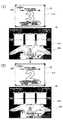
図28は、保険有モードにおいて上側画像表示パネル及び下側画像表示パネルに表示される画像の一例を示す図である。図28の(1)は、図27の(3)の状態で単位ゲームが実行され、ゲーム回数がカウントされた結果、残りゲーム数が1減少し5ゲームになった場合の画像を示す図である。図の画像は、上側画像表示パネル33及び下側画像表示パネル16に表示される画像の一例(上側画像311、下側画像411)である。上側画像311及び下側画像411は、ともに残りゲーム数5を表示している。また、上側画像311中のポイント表示部280は、獲得ポイントが「2」であることを示している。下側画像411中の下方部の天使246は、羽を少しずつ開き、レスキューペイが間近であることを演出している。この演出により、プレイヤは、レスキューペイが更に近づいたことを実感することができる。 FIG. 28 is a diagram illustrating an example of images displayed on the upper image display panel and the lower image display panel in the insurance mode. (1) in FIG. 28 is a diagram showing an image when the unit game is executed in the state of (3) in FIG. 27 and the number of games is counted, and as a result, the remaining number of games decreases by 1 to 5 games. is there. The image in the figure is an example of images displayed on the upper
図28の(2)は、図28の(1)の状態で単位ゲームが実行され、ゲーム回数がカウントされた結果、残りゲーム数が1減少し4ゲームになった場合の画像を示す図である。図の画像は、上側画像表示パネル33及び下側画像表示パネル16に表示される画像の一例(上側画像312、下側画像412)である。上側画像312及び下側画像412は、ともに残りゲーム数4を表示している。また、上側画像312中のポイント表示部280は、獲得ポイントが「2」であることを示している。下側画像412中の下方部の天使248は、羽を大きく開き、レスキューペイが目前であることを演出している。この演出により、プレイヤは、レスキューペイが更に近づいたことを実感することができる。 (2) of FIG. 28 is a diagram showing an image when the unit game is executed in the state of (1) of FIG. 28 and the number of games is counted, and as a result, the number of remaining games is reduced to 1 and becomes 4 games. is there. The image in the figure is an example of images displayed on the upper
図29は、保険有モードにおいて上側画像表示パネル及び下側画像表示パネルに表示される画像の一例を示す図である。図29の(1)は、図28の(2)の状態で単位ゲームが実行され、ゲーム回数がカウントされた結果、残りゲーム数が1減少し3ゲームになった場合の画像を示す図である。図の画像は、上側画像表示パネル33及び下側画像表示パネル16に表示される画像の一例(上側画像313、下側画像413)である。上側画像313及び下側画像413は、ともに残りゲーム数3を表示している。また、上側画像313中のポイント表示部280は、獲得ポイントが「2」であることを示している。下側画像413中の下方部の天使248は、羽を大きく開き、レスキューペイが目前であることを演出している。この演出により、プレイヤは、レスキューペイが更に近づいたことを実感することができる。 FIG. 29 is a diagram illustrating an example of images displayed on the upper image display panel and the lower image display panel in the insurance mode. (1) of FIG. 29 is a diagram showing an image when the unit game is executed in the state of (2) of FIG. 28 and the number of games is counted, and as a result, the number of remaining games is reduced by 1 to 3 games. is there. The image in the figure is an example of images displayed on the upper
図29の(2)は、図29の(1)の状態で単位ゲームが実行され、ゲーム回数がカウントされた結果、残りゲーム数が1減少し2ゲームになった場合の画像を示す図である。図の画像は、上側画像表示パネル33及び下側画像表示パネル16に表示される画像の一例(上側画像314、下側画像414)である。上側画像314及び下側画像414は、ともに残りゲーム数2を表示している。また、上側画像314中のポイント表示部280は、獲得ポイントが「2」であることを示している。下側画像414中の下方部の天使248は、羽を大きく開き、レスキューペイが目前であることを演出している。この演出により、プレイヤは、レスキューペイが更に近づいたことを実感することができる。 (2) of FIG. 29 is a diagram showing an image when the unit game is executed in the state of (1) of FIG. 29 and the number of games is counted, and as a result, the remaining number of games is reduced by 1 to 2 games. is there. The image in the figure is an example of images displayed on the upper
図30は、保険有モードにおいて上側画像表示パネル及び下側画像表示パネルに表示される画像の一例を示す図である。図29の(2)の状態で単位ゲームが実行され、ゲーム回数がカウントされた結果、残りゲーム数が1減少し1ゲームになった場合の画像を示している。図の画像は、上側画像表示パネル33及び下側画像表示パネル16に表示される画像の一例(上側画像315、下側画像415)である。上側画像315及び下側画像415は、ともに残りゲーム数1を表示している。また、上側画像315中のポイント表示部280は、獲得ポイントが「2」であることを示している。下側画像415中の下方の天使249は、羽を更に大きく開き、レスキューペイが直前であることを演出している。この演出により、プレイヤは、レスキューペイの直前であることを実感することができる。 FIG. 30 is a diagram illustrating an example of images displayed on the upper image display panel and the lower image display panel in the insurance mode. FIG. 29 shows an image when the unit game is executed in the state of (2) in FIG. 29 and the number of games is counted, and as a result, the number of remaining games is reduced by 1 to 1 game. The image in the figure is an example of images displayed on the upper
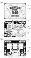
図31は、図30の状態で単位ゲームが実行され、ゲーム回数がカウントされた結果、残りゲーム数が1減少し0ゲームになり、還元モードに入るか否かを選択する画像を示す図である。図の画像は、上側画像表示パネル33に表示される画像の一例である。図31によると、還元モードに入りレスキューペイとしての払い出しを受けるか否かを、プレイヤに選択させる様子を示しており、払い出しを受けることを選択するための画像であるYES261と、払い出しを受けないことを選択するための画像であるNO262とを表示している。プレイヤは、画像YES261の表示領域に対応するタッチパネル69の所定箇所に触れることにより、レスキューペイとしての払出しを受ける旨の指示を入力することができる。また、ポイント表示部280は、獲得ポイントが「2」であることを示している。 FIG. 31 is a diagram showing an image for selecting whether or not to enter the return mode as a result of the unit game being executed in the state of FIG. is there. The image in the figure is an example of an image displayed on the upper
ここで、図13によれば、獲得ポイントが「2」である場合、倍率は「1.5倍」である。よって、レスキューペイとしての払出しを受ける場合には、YES261にタッチし、通常のレスキューペイの払出しの1.5倍の払出しを受けることができる。 Here, according to FIG. 13, when the acquired point is “2”, the magnification is “1.5 times”. Therefore, when paying out as a rescue pay, the user can touch
一方、図13で上述したとおり、獲得ポイントが所定の値に到達すると、倍率が増える。よって、プレイヤは、NO262にタッチすることで敢えてレスキューペイの払出しを受けずに、保険モード無モードに一旦移行させて、もう一度保険有モードを選択して、さらにポイントを増やすことによって、次回のレスキューペイの払出しをさらに大きな倍率で受けることが可能になる。 On the other hand, as described above with reference to FIG. 13, when the acquired points reach a predetermined value, the magnification increases. Therefore, the player does not receive the payout of the rescue pay by touching NO262, but once shifts to the non-insurance mode, selects the insured mode again, and further increases the points, the next rescue Payouts can be received at a higher magnification.
このことにより、スロットゲームの払出しに限らず、レスキューペイの払出しにおいて、獲得したポイントに応じた倍率をレスキューペイの払出クレジットに掛けて払出しを受けることができるので、所定のシンボルの組合せの成立によるポイントの獲得にプレイヤはさらに関心をもつことができる。 As a result, not only in the payout of the slot game but also in the payout of the rescue pay, it is possible to receive the payout by multiplying the payout payout credit by a rate corresponding to the earned points. Players can be more interested in earning points.
また、レスキューペイの払出しを敢えて受けずに、ポイントをさらに増やして次回のレスキューペイの際にさらに大きな払出しを受けることもできるので、プレイヤの損失の救済のためのゲームにギャンブル性を付加したゲームを提供することができる。 In addition, you can increase the number of points and receive a larger payout at the next rescue pay without taking out the payout of the rescue pay, so a game that adds gambling to the game to save the player's loss Can be provided.
図32は、還元モード移行時に上側画像表示パネル及び下側画像表示パネルに表示される画像の一例を示す図である。図32の(1)は、図31において、画像YES261の表示領域に対応するタッチパネル69の所定箇所にプレイヤからの接触があったことにより、還元モードに入った場合の画像を示す図である。図の画像は、上側画像表示パネル33及び下側画像表示パネル16に表示される画像の一例(上側画像316、下側画像416)である。上側画像316は、レスキューペイとして360の1.5倍である540クレジットを支払うことを大きく表示している。下側画像416は、還元モードでゲームが行われ、表示窓15L、15C、15RのシンボルがDOの組合せとなり(画像254)、役に相当しているので、90クレジットが支払われ、CREDITが876(786+90)となったことを示す画像を表示している。更に、下側画像416は、レスキューペイが支払われることを示す画像252と、レスキューペイを受け取るように促す天使の画像253を表示している。 FIG. 32 is a diagram illustrating an example of images displayed on the upper image display panel and the lower image display panel when shifting to the return mode. (1) of FIG. 32 is a diagram illustrating an image when the player enters the return mode due to contact from the player at a predetermined position on the
図32の(2)は、還元モードが終了した場合、下側画像表示パネル16に表示される画像の一例(下側画像417)を示す図である。レスキューペイとして540クレジットが支払われた結果、下側画像417は、CREDITを1416(876+540)と表示し、還元モードが終了したことを示す「RESCUE OFF」の画像255を表示している。 (2) of FIG. 32 is a diagram illustrating an example (lower image 417) of an image displayed on the lower
図19は、図10に示したサブルーチンのステップS26において呼び出されて実行される停止シンボル決定処理のサブルーチンを示すフローチャートである。この処理は、RAM43に記憶された抽選プログラムをメインCPU41が実行することによって行われる処理である。まず、メインCPU41は、抽選プログラムに含まれる乱数発生用プログラムを実行することにより、0〜255の数値範囲の中から、3つのリール14のそれぞれに対応する乱数値を選択する(ステップS91)。本実施形態では、プログラム上で乱数を発生させる場合(いわゆるソフトウェア乱数を用いる場合)について説明する。ただし、本発明においては、乱数発生器を設けておいて該乱数発生器から乱数を抽出する(いわゆるハードウェア乱数を用いる)こととしてもよい。 FIG. 19 is a flowchart showing a subroutine of stop symbol determination processing that is called and executed in step S26 of the subroutine shown in FIG. This process is a process performed by the
次に、メインCPU41(演算処理装置)は、GAL54から出力されてRAM43(記憶装置)に記憶されたペイアウト率設定用データに応じたシンボル重み付けデータを参照し、選択された3つの乱数値に基づいて、各リール14のコードNo.(図3参照)を決定する(ステップS92)。各リール14のコードNo.は、入賞ライン上に再配置されるシンボルのコードNo.に対応している。メインCPU41は、各リール14のコードNo.を決定することにより、役を決定する。例えば、各リール14のコードNo.を“00”、“00”、“00”に決定した場合、メインCPU41は、役を「DO」に決定したことになる。なお、このリールのコードNo.に基づいて、後述するリールの回転制御処理が行われる。 Next, the main CPU 41 (arithmetic processing unit) refers to the symbol weighting data corresponding to the payout rate setting data output from the
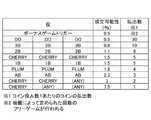
ここで、本実施形態における役について説明する。図20は、本実施形態における複数種類の役と各役の成立可能性及び払出数との関係を説明するための図である。図20に示す各役の成立可能性は、ボーナスゲーム以外におけるペイアウト率が88%である場合のものである。なお、図中に示す成立可能性は、シンボル重み付けデータを参照して3つの乱数値に基づいて、各リール14のコードNo.を決定した場合に、当該役が成立する可能性を示すものである。すなわち、各役に対して乱数値が対応付けられているものではない。 Here, the combination in this embodiment will be described. FIG. 20 is a diagram for explaining a relationship between a plurality of types of combinations, the possibility of establishment of each combination, and the number of payouts in the present embodiment. The possibility of establishment of each combination shown in FIG. 20 is that in the case where the payout rate other than the bonus game is 88%. Note that the possibility of establishment shown in the figure refers to the code number of each
ボーナスゲームトリガーの成立可能性は、0.5%である。ボーナスゲームトリガーに当選すると、「7」のシンボルが入賞ライン上に3つ再配置され、ボーナスゲームが発生する。ボーナスゲームでは、抽選によって定められた回数のフリーゲームを実行する。 The probability of establishing the bonus game trigger is 0.5%. When the bonus game trigger is won, three “7” symbols are rearranged on the winning line, and a bonus game is generated. In the bonus game, the free game is executed a number of times determined by lottery.
「DO」の成立可能性は0.5%である。この役が成立すると、「DO」のシンボルが入賞ライン上に3つ再配置され、コイン投入数1枚あたり30枚のコインが払い出される。成立可能性は低い役ほど、払出数は多く設定されている。ただし、図20に示した役のいずれの組合せにもならないシンボルの組合せが再配置された場合は、ハズレであり、コインの払い出しは行われない。 The probability of establishment of “DO” is 0.5%. When this combination is established, three “DO” symbols are rearranged on the winning line, and 30 coins are paid out per coin inserted. The number of payouts is set higher as the role is less likely to be established. However, if a combination of symbols that cannot be any combination of the combinations shown in FIG. 20 is rearranged, it is a loss and no coins are paid out.
図21は、図10に示したサブルーチンのステップS27において呼び出されて実行されるリール回転制御処理のサブルーチンを示すフローチャートである。なお、この処理は、メインCPU41とサブCPU61との間で行われる処理である。 FIG. 21 is a flowchart showing a reel rotation control process subroutine called and executed in step S27 of the subroutine shown in FIG. This process is a process performed between the
まず、メインCPU41は、サブCPU61に対して、リールの回転を開始させる旨のスタート信号を送信する(ステップS101)。サブCPU61は、メインCPU41からスタート信号を受信すると、リール回転処理を行う(ステップS111)。この処理において、サブCPU61は、モータ駆動回路62にパルスを供給する。サブCPU61から出力されたパルスは、ドライバ64によって増幅され、各ステッピングモータ70(70L、70C、70R)に供給される。その結果、各ステッピングモータ70が回転し、それに伴って各リール14(14L、14C、14R)が回転する。1−2相励磁方式のステッピングモータ70は、ステップ角が0.9°であり、1回転あたりのステップ数が400である。したがって、400個のパルスがステッピングモータ70に供給されると、リール14は1回転する。 First, the
リール14の回転開始時には、サブCPU61は、周波数が低いパルスをモータ駆動回路62に供給し、次第にパルスの周波数を高くしていく。それに伴って、リール14の回転速度が大きくなる。そして、所定の時間が経過すると、パルスの周波数を一定にする。その結果、リール14が定速で回転する。 At the start of rotation of the
ここで、リール14の回転動作について図22を用いて説明する。図22は、リール14の回転動作について説明するための側面図である。図22に示すように、リール14の側面には、半円形状の金属板14aが設けられている。金属板14aは、リール14とともに回転する。また、リール14の周面には22個のシンボル(図3参照)が設けられている。リール14の周面に描かれた22個のシンボルのうち、3個のシンボルが、リール14の前方に形成された表示窓15を介して視認可能となる。図中、太線の矢印は、リール14の回転方向を示している。また、リール14の側方には、近接センサ65aが設けられている。近接センサ65aは、金属板14aを検出するためのものである。近接センサ65aは、リール14が回転しても、移動したり回転したりすることはない。 Here, the rotation operation of the
図22の(1)には、近接センサ65aによって金属板14aが検出されはじめる時点の金属板14aの位置(以下、位置Aともいう)を示している。金属板14aが位置Aにあるときにリール14が回転すると、金属板14aは、図22の(1)に示した位置に移動する。図22の(2)には、近接センサ65aによって金属板14aが検出されているときの金属板14aの位置(以下、位置Bともいう)を示している。金属板14aが位置Bにあるときにリール14が回転すると、金属板14aは、図22の(3)に示した位置に移動する。図22の(3)には、近接センサ65aによって金属板14aが検出されなくなる時点の金属板14aの位置(以下、位置Cともいう)を示している。 FIG. 22 (1) shows the position of the
金属板14aが位置Cにあるときにリール14が回転すると、金属板14aは、図22の(4)に示した位置に移動する。図22の(4)には、近接センサ65aによって金属板14aが検出されていないときの金属板14aの位置(以下、位置Dともいう)を示している。更にリール14が回転すると、金属板14aの位置は、位置Aに戻る。上述したように、リール14の回転に伴って、金属板14aの位置は、位置A、位置B、位置C、位置D、位置A、・・・の順に変化する。 When the
近接センサ65aは、インデックス検出回路65(図4参照)を構成するものである。近接センサ65aが金属板14aを検出している状態を“High”、近接センサ65aが金属板14aを検出していない状態を“Low”とすると、金属板14aが位置A→位置B→位置Cにあるとき、インデックス検出回路65の状態は“High”であり、金属板14aが位置C→位置D→位置Aにあるとき、インデックス検出回路65の状態は“Low”である。なお、サブCPU61は、“Low”から“High”への立ち上がりをインデックス(原点)1とし、“High”から“Low”への立ち下がりをインデックス(原点)2として、リール14の回転位置を認識する。 The
メインCPU41は、ステップS101においてサブCPU61に対してスタート信号を送信した後、リール回転時の演出を実行する(ステップS102)。この処理は、停止シンボル決定処理(図10、ステップS26)の結果等に応じて定められる期間(例えば3秒)にわたって、下側画像表示パネル16への画像の表示や、スピーカ29からの音の出力等を行う処理である。 After transmitting a start signal to the
次に、メインCPU41は、リール14の回転の停止を指示するタイミングであるか否かを判断する(ステップS103)。ここで、リール14の回転の停止を指示するタイミングは、リール回転時の演出を終了する時点から、リール14の回転を停止させるために最低限必要な時間だけ前のタイミングである。なお、リール14の回転を停止させるために最低限必要な時間は、予め定められている。 Next, the
ステップS103において、リール14の回転の停止を指示するタイミングではないと判断した場合、ステップS103に処理を戻し、引き続きリール回転時の演出を行う。一方、ステップS103において、リール14の回転の停止を指示するタイミングであると判断した場合、メインCPU41は、RAM43に記憶されたリールのコードNo.をサブCPU61に送信する(ステップS104)。サブCPU61は、メインCPU41からリールのコードNo.を受信すると、サブCPU61が備えるROM(図示せず)に記憶されたステップ数とコードNo.との対応表に基づいて、コードNo.を、インデックスからのリールの停止位置(ステップ数)に換算する(ステップS112)。 If it is determined in step S103 that it is not the timing to instruct to stop the rotation of the
図23は、ステップ数とコードNo.との対応表を示した模式図である。各コードNo.には、インデックスと、ステップ数とが対応付けられている。なお、各コードNo.は、リール14の外周面に描かれたシンボルに対応していて(図3参照)、コードNo.“00”〜“10”のシンボルは、インデックス1に対応している。また、コードNo.“11”〜“21”のシンボルは、インデックス2に対応している。また、図23に示す対応表におけるステップ数は、インデックス1を基準としたステップ数である。例えば、コードNo.が“08”であれば、インデックス1から145ステップが、リールの停止位置である。また、コードNo.が“12”であれば、インデックス1から218ステップが、リールの停止位置である。 FIG. 23 shows the number of steps and the code number. It is the schematic diagram which showed the corresponding | compatible table | surface. Each code No. Is associated with an index and the number of steps. Each code No. Corresponds to the symbol drawn on the outer peripheral surface of the reel 14 (see FIG. 3). Symbols “00” to “10” correspond to
次に、サブCPU61は、リール停止処理を実行する(ステップS113)。この処理において、サブCPU61は、インデックス検出回路65における“Low”から“High”への立ち上がり(インデックス1)の検出を各リール14に対して行い、インデックス1を検出したタイミングで、ステップS112においてコードNo.から換算されたステップ数に相当するパルスをモータ駆動回路62に供給し、その後、パルスの供給を停止する。 Next, the
例えば、ステップS112において、リールの停止位置が、インデックス1から145ステップであると決定された場合、サブCPU61は、インデックス1を検出したタイミングで、145個のパルスをモータ駆動回路62に供給し、その後、パルスの供給を停止する。また、ステップS112において、リールの停止位置が、インデックス1からの218ステップであると決定された場合、サブCPU61は、インデックス1を検出したタイミングで、218個のパルスをモータ駆動回路62に供給する。その結果、リール14が、図19のステップS92において決定されたコードNo.のとおりに停止し、入賞ライン上には、図19のステップS92において決定された役に対応するシンボルの組合せが再配置される。一方、メインCPU41は、リール回転時の演出を終了する。ステップS105及びS113の処理を終了した後、本処理を終了する。 For example, if it is determined in step S112 that the reel stop position is from
なお、ステップS104において送信されたコードNo.に対応するインデックスと、リール14の回転が停止したときにインデックス検出回路65によって検出されるインデックスとが異なる場合、リール14に脱調が生じているので、メインCPU41は、エラーメッセージを下側画像表示パネル16に表示する等の処理を行い、遊技を中断する。例えば、インデックス2に対応するコードNo.12でリール14Lを停止させる処理を行ったにも関わらず、リール14Lの回転が停止したときにインデックス検出回路65によってインデックス1が検出された場合には、遊技を中断する。 It should be noted that the code No. transmitted in step S104. Is different from the index detected by the
図24は、図17に示したサブルーチンのステップS78において呼び出されて実行される保険払出処理のサブルーチンを示すフローチャートである。 FIG. 24 is a flowchart showing a subroutine of insurance payout processing that is called and executed in step S78 of the subroutine shown in FIG.
まず、メインCPU41は、保険の払出が確定したか否かを判断する。保険の払出が確定した場合には、ステップS122に処理を移す。保険の払出が確定していない場合には、本サブルーチンを終了する。具体的には、図31において、保険の払出を受けるとプレイヤが決定した場合には、保険の払出が確定する。 First, the
ステップS122では、メインCPU41は、図12で示した倍率テーブルを参照して、ポイントカウンタに応じた倍率を取得し、ステップS123に処理を移す。 In step S122, the
ステップS123では、メインCPU41は、ポイントをクリアし、ステップS124に処理を移す。具体的には、RAM43の所定の領域に格納されたポイントカウンタをクリアする。 In step S123, the
ステップS124では、メインCPU41は、保険に倍率を掛けて払出す。具体的には、ステップS122で取得した倍率に還元モードでのペイアウト数(本実施例では360クレジット)を掛けた数のクレジットを払出す。この処理が終了すると、メインCPU41は、本サブルーチンを終了する。 In step S124, the
図25は、図14又は図15に示したサブルーチンのステップS42又はステップS52において呼び出されて実行されるボーナスゲーム処理のサブルーチンを示すフローチャートである。ボーナスゲーム処理においては、まず、メインCPU41は、RAM43に記憶された抽選プログラムに含まれる乱数発生プログラムを実行して得られた乱数値に基づいて、10〜25ゲームのいずれかの中から決定する(ステップS131)。メインCPU41は、決定したボーナスゲームのゲーム数をデータとしてRAM43に記憶する。 FIG. 25 is a flowchart showing a bonus game process subroutine that is called and executed in step S42 or step S52 of the subroutine shown in FIG. In the bonus game process, first, the
続いて、メインCPU41は、停止シンボル決定処理(ステップS132)及びリール回転制御処理(ステップS133)を行う。ステップS132の処理は、図19を用いて説明した処理と略同様の処理である。また、ステップS133の処理は、図21を用いて説明した処理と略同様の処理である。これらの処理については、既に説明済であるから、ここでの説明は省略する。 Subsequently, the
次に、メインCPU41は、ボーナスゲームトリガーが成立したか否か、すなわち、表示窓15内に「7」が再配置されたか否かを判断する(ステップS134)。ボーナスゲームトリガーが成立したと判断した場合には、ボーナスゲームの繰り返し回数tが新たに抽選により決定され(ステップS135)、その決定された繰り返し回数tは、現在のボーナスゲームのゲーム数Tに加算される(ステップS136)。これにより、ボーナスゲーム中にボーナスゲームに当選すると、ボーナスゲームの残り回数が増える。具体的に言えば、例えば、20回のボーナスゲームにはじめて移行した場合に、そのボーナスゲームの12回目で17回のボーナスゲームに当選したときには、その後、25回(20回−12回+17回)のボーナスゲームが行われる。 Next, the
ボーナスゲームトリガーが成立しなかった場合、メインCPU41は、役が成立したか否かを判断する(ステップS137)。役が成立したと判断した場合、メインCPU41は、投入数及び役に応じたコインの払い出しを行う(ステップS138)。 When the bonus game trigger has not been established, the
ステップS136若しくはS138の処理を実行した場合、又は、ステップS137において、いずれの役も成立していないと判断した場合(ハズレであると判断した場合)、メインCPU41は、RAM43に記憶されたボーナスゲームのゲーム数Tを読み出し、読み出したゲーム数Tの値を1減算する。そして、減算後のゲーム数Tを再びRAM43に格納する(ステップS139)。 When the process of step S136 or S138 is executed, or when it is determined in step S137 that no combination is established (when it is determined that the game is lost), the
次に、メインCPU41は、ボーナスゲームの回数Tが、ステップS131で決定された回数に到達したか否かを判断する(ステップS140)。具体的には、RAM43に記憶されたゲーム数Tが0となったか否かにより判断し、ゲーム数Tが0でない場合、すなわちボーナスゲームの実行回数が、ステップS131で決定された回数に到達していないと判断する場合、ステップS132に処理を戻し、上述した処理を繰り返す。一方、ゲーム数Tが0である場合、すなわち、ステップS131で決定された回数に到達したと判断した場合には、その後、本サブルーチンを終了する。 Next, the
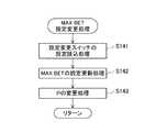
図33は、MAXBET設定変更処理のサブルーチンを示すフローチャートである。この処理は、MAXBETとしてベットする値の設定変更を行う。図34は、MAXBETの設定値とMAXBET時のペイアウト値とを対応付けているテーブルを示す図である。このテーブルは、MAXBETとしてベットする値の設定変更を行う際に用いられ、MAXBETとしてベットする値と、保険有モードにおけるペイアウトの上限値(P)とを対応付けている。 FIG. 33 is a flowchart showing a subroutine of the MAXBET setting change process. This process changes the setting of the value to bet as MAXBET. FIG. 34 is a diagram showing a table in which MAXBET setting values are associated with MAXBET payout values. This table is used when changing the setting of the value to bet as MAXBET, and associates the value to bet as MAXBET with the upper limit (P) of payout in the insurance mode.
まず、メインCPU41は、設定変更スイッチ85の設定を読み込む処理を行う(ステップS141)。ここで、設定変更スイッチ85とは、MAXBETの値を変更する入力装置である。設定変更スイッチ85は、電源投入時等に遊技機10の管理者が変更を行う。次に、MAXBETの設定を更新する処理を行う(ステップS142)。次に、保険有モードにおけるペイアウトの上限値(P)の変更処理を行う(ステップS143)。この処理で、メインCPU41は、テーブル(図34)を介して、読み込んだ設定変更スイッチの値に応じた上限値(P)を求め、MAXBETとしてベットする値に対応する上限値として変更する。保険有モードでは、この上限値より高いペイアウトが行われるとゲーム回数又は保険有モードがリセットされる(図14又は図15参照)。したがって、上限値を高い値に設定しておけば(例えば、MAXBETとしてベットする値を50に設定すると上限値は3000)、保険有モードにおいて、入賞した場合であっても、上限値が高いので、容易にはゲーム回数又は保険有モードがリセットされない。ステップS143の処理を終了した後、メインCPU41は、本サブルーチンを終了する。 First, the
本実施形態では、保険有モードにおいて、MAXBETでゲームを行う時にゲーム回数をカウントし、ゲーム回数が特定回数に達すると還元モードへ移行する場合について説明した(図10参照)。ただし、本発明は、この例に限定されるものではない。例えば、MAXBETでなくても、ゲームごとにゲーム回数をカウントし特定回数に達したとき還元モードへ移行することとしてもよい。 In the present embodiment, a case has been described in which the number of games is counted when a game is played with MAXBET in the insurance mode, and the mode is shifted to the return mode when the number of games reaches a specific number (see FIG. 10). However, the present invention is not limited to this example. For example, even if it is not MAXBET, the number of games may be counted for each game, and the mode may be shifted to the return mode when the specific number is reached.
以上、本実施形態に係る遊技機10は、メインCPU41(演算処理装置)と、RAM43(記憶装置)と、上側画像表示パネル33及び下側画像表示パネル16とを備え、メインCPU41は、RAM43に記憶された抽選プログラムを実行することにより、予め定められた複数種類の役の中から選択される1つの役を決定する処理(図19参照)と、所定数のクレジットが投入されたことを条件として、保険無モードから保険有モードに移行するためのプログラムをRAM43から読み出して実行する処理(図6参照)と、保険有モードに移行していることを報知するための報知用データ及び演出用データをRAM43から読み出し、報知用データ及び演出用データに基づいて上側画像表示パネル33及び下側画像表示パネル16に画像(図26の(1)等参照)を表示する処理(図17等参照)と、保険有モードに移行した後から、MAXBETで遊技が行われるごとにゲーム回数をカウントし(図10参照)、特定回数とゲーム回数との差を表示(図26の(1)等参照)し、ゲーム回数が特定回数に達したときに、還元モードへの移行を行うためのプログラムをRAM43から読み出して実行する処理(図17参照)と、役を判定しボーナスゲームの場合、ゲーム回数若しくは保険有モードをリセットする処理(図14参照)と、役によるペイアウトが所定以上の場合にゲーム回数若しくは保険有モードをリセットする処理(図15参照)と、MAXBETの設定とペイアウト値を変更する処理(図33参照)と、を実行することを特徴とする遊技機である。 As described above, the
遊技機10によれば、所定数のクレジットが投入されたことを条件として、保険無モードから保険有モードに移行する。そして、保険有モードに移行した後から、MAXBETで遊技が行われるごとに累積的に計数されるゲーム回数が特定回数に達したとき、還元モードに移行する。したがって、プレイヤは、所定数のクレジットを投入して、保険無モードから保険有モードに移行させることができる。また、保険有モードにおいては、長期間にわたってボーナスゲームが発生せずに多数のコインを消費した場合等であっても、ゲーム回数が特定回数に達するまで遊技を行えば、還元モードに移行し、プレイヤは、その利益を得ることができる。一方、保険有モードに移行するためには、プレイヤが所定数のクレジットを投入することが必要であり、MAXBETで遊技を行う場合のみ、ゲーム回数がカウントされるので、遊技によって利益を得ているプレイヤとの公平が保たれる。 According to the
更に、保険有モードに移行していることを報知する画像(図9の(1)参照)が表示されるとともに、特定回数とゲーム回数との差が表示されるため、保険有モードに移行していることをプレイヤに認識させることができるだけでなく、更に還元モードに対する興味や関心を高めることができる。したがって、多数のコインを消費したプレイヤが、遊技機に対して不快感や不信感を募らせたり、遊技に対する興味や関心を失ったりすることを防止することができる。 In addition, an image (see (1) in FIG. 9) for notifying that the mode is shifted to the insurance mode is displayed and the difference between the specific number of times and the number of games is displayed. In addition to allowing the player to recognize that it is, the interest and interest in the reduction mode can be further increased. Therefore, it is possible to prevent a player who has consumed a large number of coins from causing discomfort and distrust to the gaming machine or losing interest in the game.
また、本実施形態に係る遊技機10は、ゲーム回数が特定回数に達したとき、還元モードへの移行が行われるものであるが、本発明は、この例に限定されるものではない。本発明の遊技機10は、コインの収支が特定回数以下になったとき、還元モードへの移行が行われるものであってもよい。 Further, in the
本実施形態では、プレイヤ識別情報については特に触れなかったが、本発明においては、例えば、プレイヤごとにプレイヤ識別情報を付与し、プレイヤ識別情報に対応付けて各プレイヤの所定の変数(例えば、ゲーム回数、クレジットの収支)を累積的に計数することとしてもよい。このようにする場合、遊技開始時又は保険有モードへの移行時に、プレイヤ識別情報の入力を要求することとし、プレイヤ識別情報が入力された時点で、それまでに計数されていた所定の変数を0に戻す処理を行えばよい。このようにした場合、多数のクレジットを消費したプレイヤに対してより確実に還元を行うことが可能になるため、遊技に対するプレイヤの興味や関心をより高めることができる。 In the present embodiment, the player identification information is not particularly mentioned. However, in the present invention, for example, player identification information is given to each player, and a predetermined variable (for example, a game) of each player is associated with the player identification information. The number of times and the balance of credits) may be counted cumulatively. In this case, at the start of the game or at the time of transition to the insurance mode, the player identification information is requested to be input, and when the player identification information is input, the predetermined variable that has been counted so far is What is necessary is just to perform the process which returns to 0. In this case, the player who has consumed a large number of credits can be more reliably paid back, so that the player's interest and interest in the game can be further increased.
本実施形態では、シンボルが再配置され(図10、ステップS27)、再配置されたシンボルの組合せに基づく処理(図10、ステップS29)が行われた後、ゲーム回数の計数(図10、ステップS30)が行われる場合について説明した。しかし、本発明において、ゲーム回数の計数が行われるタイミングは、特に限定されるものではない。例えば、シンボルの表示が開始されてから、シンボルが再配置され、再配置されたシンボルの組合せに基づく処理が行われるまでの所定のタイミング(例えば、シンボルが再配置されたタイミング)で、ゲーム回数の計数が行われることとしてもよい。なお、クレジットの収支を計数するタイミングについても、上述したものを採用することが可能である。 In this embodiment, symbols are rearranged (FIG. 10, step S27), and after processing based on the rearranged symbol combination (FIG. 10, step S29) is performed, the number of games is counted (FIG. 10, step S29). The case where S30) is performed has been described. However, in the present invention, the timing at which the number of games is counted is not particularly limited. For example, the number of games at a predetermined timing (for example, the timing at which symbols are rearranged) from when symbol display is started until symbols are rearranged and processing based on the rearranged symbol combination is performed. The counting may be performed. Note that the above-described timing can also be adopted for counting the credit balance.
上記実施の形態では、本発明をメカニカルリールスロットマシンに適用した例について記載したが、本発明はビデオリールスロットマシンにも適用してもよい。また、本発明は透明液晶にシンボルを表示するようにしてもよい。これは、本発明がシンボルの変動表示及び停止表示の態様に制約を受けないことを意味する。 In the above embodiment, an example in which the present invention is applied to a mechanical reel slot machine has been described, but the present invention may also be applied to a video reel slot machine. In the present invention, the symbol may be displayed on the transparent liquid crystal. This means that the present invention is not constrained by the manner of symbol change display and stop display.
また、本発明においては、ポイントを獲得するためのシンボル組合せは「7」「7」「DORA」に限られず、他の組合せであってもよい。 In the present invention, symbol combinations for obtaining points are not limited to “7”, “7”, and “DORA”, but may be other combinations.
また、本発明においては、ゲーム回数が特定回数に達してから、還元モードを発生させるまでの間に、特別の役が成立した場合には、還元モードのみを発生させることとしてもよく、ボーナスゲーム及び還元モードのいずれか1を遊技状況等に応じて選択し、発生させることとしてもよい。 Further, in the present invention, when a special combination is established between the time when the number of games reaches a specific number of times and the time when the return mode is generated, only the return mode may be generated. Further, any one of the return mode and the return mode may be selected and generated according to the game situation or the like.
なお、クレジットの収支に応じて還元モードを発生させる場合についても、上述した形態と同様の形態を採用することができる。すなわち、クレジットの収支が特定回数以下となってから、還元モードを発生させるまでの間に、特別の役が成立した場合には、ボーナスゲームのみを発生させることとしてもよく、還元モードのみを発生させることとしてもよく、ボーナスゲーム及び還元モードのいずれか1を遊技状況等に応じて選択し、発生させることとしてもよいのである。 Note that the same mode as described above can also be adopted in the case where the return mode is generated according to the credit balance. In other words, if a special combination is established between when the credit balance is less than a specific number of times and when the return mode is generated, only the bonus game may be generated, and only the return mode is generated. Alternatively, any one of the bonus game and the return mode may be selected and generated according to the game situation or the like.
また、ゲーム回数が特定回数に達したとき、フリーゲーム、セカンドゲーム、ミステリーボーナス等と同様の形態での特典をプレイヤに付与する還元モードを設定可能に構成し、これらの形態のいずれかによって、所定数のクレジットの払い出しを行うこととしてもよい。 In addition, when the number of games reaches a specific number, it is configured to be able to set a return mode that gives a player a privilege in the same form as a free game, a second game, a mystery bonus, etc. A predetermined number of credits may be paid out.
また、所定数のクレジットの払い出しを行うタイミングとしては、前述したようなミステリーボーナスのように、単位ゲームが終了してシンボルが再配置されたタイミングに限定されるものではなく、例えば、ゲーム回数が特定回数に達したとき、直ちにクレジットの払い出しを行うこととしてもよい。 Further, the timing of paying out a predetermined number of credits is not limited to the timing at which the unit game is completed and the symbols are rearranged as in the mystery bonus as described above. When a specific number of times is reached, credits may be paid out immediately.
更に、所定数のクレジットの払い出し方法としても、特に限定されるものではなく、例えば、実際にコインを払い出すこととしてもよく、クレジット数を増加させることとしてもよい。 Further, the method for paying out a predetermined number of credits is not particularly limited, and for example, coins may be actually paid out or the number of credits may be increased.
しかしながら、プレイヤが通常の遊技やボーナスゲームによる払い出しを受けたのか、還元モードによる払い出しを受けたのかを区別して認識することができるようにするためには、以下のようにする必要がある。すなわち、還元モードにおけるミステリーボーナスで実際にコインを払い出す場合には、そのタイミングを、通常の遊技やボーナスゲームとは異なるタイミングで払い出す必要がある。また、通常の遊技やボーナスゲームでの払い出しを実際のコインで行い、還元モードでの払い出しをクレジットで行う必要がある。このようにすることによって、通常の遊技やボーナスゲームの遊技での払い出しと、還元モードでの払い出しとを差別化することができる。 However, in order to distinguish and recognize whether the player has received a payout in a normal game or bonus game or a payout in the return mode, it is necessary to do the following. That is, when coins are actually paid out with a mystery bonus in the return mode, the timing needs to be paid out at a timing different from that of a normal game or bonus game. Further, it is necessary to pay out in a normal game or bonus game with actual coins, and to pay out in the return mode with credits. By doing so, it is possible to differentiate between payouts in normal games and bonus games and payouts in the return mode.
以上、本発明の実施形態を説明したが、具体例を例示したに過ぎず、特に本発明を限定するものではなく、各手段等の具体的構成は、適宜設計変更可能である。また、本発明の実施形態に記載された効果は、本発明から生じる最も好適な効果を列挙したに過ぎず、本発明による効果は、本発明の実施形態に記載されたものに限定されるものではない。 The embodiment of the present invention has been described above, but only specific examples are illustrated, and the present invention is not particularly limited. The specific configuration of each unit and the like can be appropriately changed in design. The effects described in the embodiments of the present invention are only the most preferable effects resulting from the present invention, and the effects of the present invention are limited to those described in the embodiments of the present invention. is not.
10 遊技機
11 キャビネット
14L、14C、14R リール
14a 金属板
15L、15C、15R 表示窓
16 下側画像表示パネル
18 コイントレイ
19 コイン払出口
20 コントロールパネル
21 コイン受入口
21C コインカウンタ
21S リバータ
22 紙幣識別器
23 スピンボタン
23S スピンスイッチ
24 チェンジボタン
24S チェンジスイッチ
25 キャッシュアウトボタン
25S キャッシュアウトスイッチ
26 1−BETボタン
26S 1−BETスイッチ
27 最大BETボタン
27S 最大BETスイッチ
29 スピーカ
30 ランプ
31 クレジット数表示部
32 ペイアウト数表示部
33 上側画像表示パネル
36 カードリーダ
37 データ表示器
38 キーパッド
38S キースイッチ
40 マザーボード
41 メインCPU
42 ROM
43 RAM
45 電源ユニット
50 ゲーミングボード
51 CPU
52 ブートROM
53 メモリカード
53S カードスロット
54S ICソケット
55 ROM
61 サブCPU
62 モータ駆動回路
64 ドライバ
65 インデックス検出回路
65a 近接センサ
66 ホッパー
67 コイン検出部
68 グラフィックボード
69 タッチパネル
70 ステッピングモータ
71 位置変更検出回路
81 冷陰極管
85 設定変更スイッチ
280 ポイント表示部
10 gaming machines
11 Cabinet
14L, 14C, 14R reel
14a Metal plate
15L, 15C, 15R Display window
16 Lower image display panel
18 coin tray
19 Coin payment exit
20 Control panel
21 Coin acceptance
21C coin counter
21S Reverter
22 bill validator
23 Spin button
23S spin switch
24 Change button
24S change switch
25 Cash out button
25S cash out switch
26 1-BET button
26S 1-BET switch
27 Maximum BET button
27S Maximum BET switch
29 Speaker
30 lamps
31 Credit number display
32 Payout number display
33 Upper image display panel
36 Card reader
37 Data display
38 Keypad
38S key switch
40 Motherboard
41 Main CPU
42 ROM
43 RAM
45 Power supply unit
50 gaming board
51 CPU
52 Boot ROM
53 Memory card
53S card slot
54S IC socket
55 ROM
61 Sub CPU
62 Motor drive circuit
64 drivers
65 Index detection circuit
65a Proximity sensor
66 Hopper
67 Coin detector
68 graphic board
69 Touch panel
70 Stepping motor
71 Position change detection circuit
81 Cold cathode tube
85 Setting change switch
280 point display
Claims (3)
Translated fromJapaneseクレジットのペイアウトに関連するポイントを記憶するメモリと、
コントローラと、を備えるスロットマシンであって、
前記コントローラは、
(a)ベットを受け付けた後、前記シンボル表示デバイスにより前記複数のシンボルの再配置を行い、前記複数のシンボルの再配置の状態に応じた数のクレジットのペイアウトを行うゲームを実行し、
(b)前記複数のシンボルの再配置の状態が所定のシンボル組合せとなる場合には、所定数のポイントを累積加算して前記メモリに記憶し、
(c)所定の条件により、保険無モードから保険有モードに移行し、
(d)前記保険有モードに移行した場合に、前記保険有モードに移行してから行われたゲーム回数をカウントし、
(e)(d)の処理によりカウントされたゲーム回数が特定回数に達した際に、前記メモリに記憶されたポイントに応じた数のクレジットのペイアウトを行うことを特徴とするスロットマシン。A symbol display device for displaying a plurality of symbols;
Memory for storing points associated with credit payouts;
A slot machine comprising a controller,
The controller is
(A) After receiving a bet, rearrange the plurality of symbols by the symbol display device, and execute a game of paying out a number of credits according to the rearrangement state of the plurality of symbols.
(B) When the rearrangement state of the plurality of symbols is a predetermined symbol combination, a predetermined number of points are accumulated and stored in the memory;
(C) Transition from non-insurance mode to insured mode under certain conditions,
(D) When transitioning to the insurance mode, count the number of games played since the transition to the insurance mode,
(E) A slot machine that pays out a credit corresponding to the number of points stored in the memory when the number of games counted by the processing of (d) reaches a specific number.
クレジットのペイアウトに関連するポイントを記憶するメモリと、
コントローラと、を備えるスロットマシンであって、
前記コントローラは、
(a)ベットを受け付けた後、前記シンボル表示デバイスにより前記複数のシンボルの再配置を行い、前記複数のシンボルの再配置の状態に応じた数のクレジットのペイアウトを行うゲームを実行し、
(b)前記複数のシンボルの再配置の状態が所定のシンボル組合せとなる場合には、所定数のポイントを累積加算して前記メモリに記憶し、
(c)所定の条件により、保険無モードから保険有モードに移行し、
(d)前記保険有モードに移行した場合に、前記保険有モードに移行してから行われたゲーム回数をカウントし、
(e)(d)の処理によりカウントされたゲーム回数が特定回数に達した際に、前記メモリに記憶されたポイントに応じた数のクレジットのペイアウトを行い、
(f)前記メモリに記憶されたポイントが所定値に到達した場合には、(e)の処理においてペイアウトを行うクレジットの数を所定量増加させることを特徴とするスロットマシン。A symbol display device for displaying a plurality of symbols;
Memory for storing points associated with credit payouts;
A slot machine comprising a controller,
The controller is
(A) After receiving a bet, rearrange the plurality of symbols by the symbol display device, and execute a game of paying out a number of credits according to the rearrangement state of the plurality of symbols.
(B) When the rearrangement state of the plurality of symbols is a predetermined symbol combination, a predetermined number of points are accumulated and stored in the memory;
(C) Transition from non-insurance mode to insured mode under certain conditions,
(D) When transitioning to the insurance mode, count the number of games played since the transition to the insurance mode,
(E) When the number of games counted by the process of (d) reaches a specific number, payout of credits corresponding to the number of points stored in the memory is performed,
(F) A slot machine characterized in that when the point stored in the memory reaches a predetermined value, the number of credits to be paid out in the process of (e) is increased by a predetermined amount.
クレジットのペイアウトに関連するポイントを記憶するメモリと、
プレーヤがクレジットのペイアウトを受けることを決定するための入力を受け付ける入力デバイスと、
コントローラと、を備えるスロットマシンであって、
前記コントローラは、
(a)ベットを受け付けた後、前記シンボル表示デバイスに対して前記複数のシンボルの再配置を行い、前記複数のシンボルの再配置の状態に応じた数のクレジットのペイアウトを行うゲームを実行し、
(b)前記複数のシンボルの再配置の状態が所定のシンボル組合せとなる場合には、所定数のポイントを累積加算して前記メモリに記憶し、
(c)所定の条件により、保険無モードから保険有モードに移行し、
(d)前記保険有モードに移行した場合に、前記保険有モードに移行してから行われたゲーム回数をカウントし、
(e)(d)の処理によりカウントされたゲーム回数が特定回数に達した際に、前記入力デバイスが前記入力を受け付けた場合には前記メモリに記憶されたポイントに応じた数のクレジットのペイアウトを行い、
(f)前記メモリに記憶されたポイントが所定値に到達した場合には、(e)の処理においてペイアウトを行うクレジットの数を所定量増加させることを特徴とするスロットマシン。A symbol display device for displaying a plurality of symbols;
Memory for storing points associated with credit payouts;
An input device that accepts input to determine that the player will receive a credit payout;
A slot machine comprising a controller,
The controller is
(A) After accepting a bet, rearrange the plurality of symbols on the symbol display device, and execute a game of paying out a number of credits according to the rearrangement state of the plurality of symbols.
(B) When the rearrangement state of the plurality of symbols is a predetermined symbol combination, a predetermined number of points are accumulated and stored in the memory;
(C) Transition from non-insurance mode to insured mode under certain conditions,
(D) When transitioning to the insurance mode, count the number of games played since the transition to the insurance mode,
(E) When the number of games counted by the processing of (d) reaches a specific number, if the input device accepts the input, the number of credit payouts corresponding to the points stored in the memory And
(F) A slot machine characterized in that when the point stored in the memory reaches a predetermined value, the number of credits to be paid out in the process of (e) is increased by a predetermined amount.
Applications Claiming Priority (2)
| Application Number | Priority Date | Filing Date | Title |
|---|---|---|---|
| US96036107P | 2007-09-26 | 2007-09-26 | |
| US12/038,540US20090082085A1 (en) | 2007-09-26 | 2008-02-27 | Slot machine performing payout of a predetermined amount of credits when the number of games reaches a predetermined number |
Publications (1)
| Publication Number | Publication Date |
|---|---|
| JP2009078119Atrue JP2009078119A (en) | 2009-04-16 |
Family
ID=40472242
Family Applications (1)
| Application Number | Title | Priority Date | Filing Date |
|---|---|---|---|
| JP2008061195APendingJP2009078119A (en) | 2007-09-26 | 2008-03-11 | Slot machine which pays out prescribed number of credits when frequency of game reaches specified value |
Country Status (2)
| Country | Link |
|---|---|
| US (1) | US20090082085A1 (en) |
| JP (1) | JP2009078119A (en) |
Cited By (2)
| Publication number | Priority date | Publication date | Assignee | Title |
|---|---|---|---|---|
| JP2017077412A (en)* | 2015-10-21 | 2017-04-27 | ネット株式会社 | Game machine |
| JP2017127540A (en)* | 2016-01-21 | 2017-07-27 | ネット株式会社 | Game machine |
Families Citing this family (1)
| Publication number | Priority date | Publication date | Assignee | Title |
|---|---|---|---|---|
| US20240144784A1 (en)* | 2022-10-26 | 2024-05-02 | Igt | Replacement game results to incentivize continued wagerging game play |
Family Cites Families (12)
| Publication number | Priority date | Publication date | Assignee | Title |
|---|---|---|---|---|
| JPH0538775Y2 (en)* | 1985-01-11 | 1993-09-30 | ||
| JP2719450B2 (en)* | 1991-01-28 | 1998-02-25 | ユニバーサル販売株式会社 | Slot machine |
| US5655961A (en)* | 1994-10-12 | 1997-08-12 | Acres Gaming, Inc. | Method for operating networked gaming devices |
| US5766075A (en)* | 1996-10-03 | 1998-06-16 | Harrah's Operating Company, Inc. | Bet guarantee system |
| US5910048A (en)* | 1996-11-29 | 1999-06-08 | Feinberg; Isadore | Loss limit method for slot machines |
| US7494416B2 (en)* | 1997-02-21 | 2009-02-24 | Walker Digital, Llc | Method and apparatus for providing insurance policies for gambling losses |
| US6004207A (en)* | 1997-12-23 | 1999-12-21 | Wms Gaming Inc. | Slot machine with incremental pay-off multiplier |
| US6270409B1 (en)* | 1999-02-09 | 2001-08-07 | Brian Shuster | Method and apparatus for gaming |
| US6960134B2 (en)* | 2002-09-12 | 2005-11-01 | Igt | Alternative bonus games associated with slot machine |
| US8029351B2 (en)* | 2005-08-18 | 2011-10-04 | Universal Entertainment Corporation | Gaming machine including a wheel and a processor to specify a pocket of the wheel |
| JP2007181579A (en)* | 2006-01-09 | 2007-07-19 | Aruze Corp | Game machine and game system |
| US8282462B2 (en)* | 2007-04-13 | 2012-10-09 | Universal Entertainment Corporation | Gaming machine with a count-value triggered insurance bonus game and playing method thereof |
- 2008
- 2008-02-27USUS12/038,540patent/US20090082085A1/ennot_activeAbandoned
- 2008-03-11JPJP2008061195Apatent/JP2009078119A/enactivePending
Cited By (2)
| Publication number | Priority date | Publication date | Assignee | Title |
|---|---|---|---|---|
| JP2017077412A (en)* | 2015-10-21 | 2017-04-27 | ネット株式会社 | Game machine |
| JP2017127540A (en)* | 2016-01-21 | 2017-07-27 | ネット株式会社 | Game machine |
Also Published As
| Publication number | Publication date |
|---|---|
| US20090082085A1 (en) | 2009-03-26 |
Similar Documents
| Publication | Publication Date | Title |
|---|---|---|
| JP2009078120A (en) | Slot machine which pays out prescribed number of credits when frequency of game reaches specified value | |
| JPWO2007026407A1 (en) | Game machine, game control method, and game system | |
| JPWO2007026404A1 (en) | Game machine, game control method, and game system | |
| JPWO2007026396A1 (en) | Game machine, game control method, and game system | |
| JPWO2007026399A1 (en) | Game machine, game control method, and game system | |
| JP2007125299A (en) | Game machine, game control method, and game system | |
| JPWO2007026400A1 (en) | Game machine, game control method, and game system | |
| JPWO2007026406A1 (en) | Game machine, game control method, and game system | |
| JPWO2007026401A1 (en) | Game machine, game control method, and game system | |
| JPWO2007026403A1 (en) | Game machine, game control method, and game system | |
| JPWO2007026402A1 (en) | Game machine, game control method, and game system | |
| JP2007125297A (en) | Game machine, game control method, and game system | |
| JP2008043746A (en) | Slot machine and control method thereof | |
| JP2007125298A (en) | Game machine, game control method, and game system | |
| JP2008093424A (en) | Slot machine and playing method thereof | |
| JP2008043743A (en) | Slot machine and playing method thereof | |
| JP2009078119A (en) | Slot machine which pays out prescribed number of credits when frequency of game reaches specified value | |
| AU2007221932A1 (en) | Gaming machine, playing method thereof and gaming system | |
| JP2008062043A (en) | Slot machine and control method thereof | |
| JP2007190134A (en) | Game machine | |
| JP5532282B2 (en) | Slot machine and game control method | |
| JP2007275204A (en) | Game machine and game program | |
| JP2008043744A (en) | Slot machine and playing method thereof | |
| JP2007275250A (en) | Game machine | |
| JP2008023161A (en) | Game machine, game system, and game control method |