JP2009075861A - Input device and input system - Google Patents
Input device and input systemDownload PDFInfo
- Publication number
- JP2009075861A JP2009075861AJP2007244200AJP2007244200AJP2009075861AJP 2009075861 AJP2009075861 AJP 2009075861AJP 2007244200 AJP2007244200 AJP 2007244200AJP 2007244200 AJP2007244200 AJP 2007244200AJP 2009075861 AJP2009075861 AJP 2009075861A
- Authority
- JP
- Japan
- Prior art keywords
- input device
- gyro
- displacement
- housing
- rotating
- Prior art date
- Legal status (The legal status is an assumption and is not a legal conclusion. Google has not performed a legal analysis and makes no representation as to the accuracy of the status listed.)
- Withdrawn
Links
Images


Landscapes
- Position Input By Displaying (AREA)
Abstract
Description
Translated fromJapanese本発明は、筐体内の回転体を回転することにより応力を発生させて使用者が筐体を操作したときに操作感(抵抗感)が感じられるようにした入力装置および入力システムに関する。 The present invention relates to an input device and an input system that allow a user to feel an operational feeling (resistance feeling) when a user operates a casing by generating stress by rotating a rotating body in the casing.
現在、ディスプレイ用のリモートコントローラ(以下、「入力装置」という)のなかには、ディスプレイ(表示装置)のメニュー画面を見ながら入力装置の筐体を、例えばスイング移動(スイング操作)や旋回移動(旋回操作)させることで、メニュー画面の入力操作や確認操作などをおこなうものがある(例えば、特許文献1参照)。
特許文献1の入力装置によれば、筐体を振ったり(スイング)旋回させることで、入力操作や確認操作ができるように構成されているので、入力操作用の操作ボタンや確認操作用の操作ボタンを少なくすることができ、使用者による操作性を向上させることができる入力装置である。 According to the input device of Patent Document 1, since the input operation and the confirmation operation can be performed by swinging (swinging) the casing, the operation button for the input operation and the operation for the confirmation operation are configured. The input device can reduce the number of buttons and improve the operability for the user.
しかし、例えば、筐体を振ったり旋回させて、メニュー画面に写った対象物の選択や操作等を行うためには、筐体の操作を適正におこなう必要がある。このため、筐体を振ったり旋回させた際に、筐体の操作状況を使用者にフィードバックさせて、筐体の操作状況や操作感を使用者に感覚的に認識させることが求められている。このような操作感を使用者に与えるために、入力装置の筐体内部にバイブレータを設け、使用者の操作に応じてバイブレータを動作させ、使用者に操作状況や操作感を感覚的にフィードバックさせることが考えられる。 However, for example, in order to select or operate an object on the menu screen by shaking or turning the casing, it is necessary to appropriately operate the casing. For this reason, when the housing is shaken or swiveled, it is required to feed back the operation status of the housing to the user so that the user can sensuously recognize the operation status and operation feeling of the housing. . In order to give such a feeling of operation to the user, a vibrator is provided inside the housing of the input device, the vibrator is operated according to the user's operation, and the user is sensibly fed back the operation status and operation feeling. It is possible.
しかしながら、特許文献1の入力装置を用いて3次元的な操作により入力を行い、その操作に応じてバイブレータによる操作感のフィードバックを行うのでは、使用者に適切な操作を促すには情報量が足りないという問題があった。また、この入力装置をゲームに使用する場合は、3次元的な操作も可能であるが、ゲームの興趣性は向上するものの、入力装置から得られるフィードバックは振動だけであり、入力装置の操作における方向性がないという問題があった。 However, if input is performed by a three-dimensional operation using the input device of Patent Document 1 and feedback of operation feeling by a vibrator is performed in accordance with the operation, the amount of information is required to prompt the user to perform an appropriate operation. There was a problem of not enough. In addition, when this input device is used in a game, three-dimensional operation is possible, but although the fun of the game is improved, the feedback obtained from the input device is only vibration, and in the operation of the input device There was a problem of lack of direction.
そこで本発明は、前述した課題を解決するためになされたもので、その目的は、入力装置を操作した際に、操作に対応した方向性を持ったフィードバックを使用者に与えることができる入力装置および入力システムを提供することにある。 Accordingly, the present invention has been made to solve the above-described problems, and an object of the present invention is to provide a user with feedback having a direction corresponding to an operation when the input device is operated. And providing an input system.
本発明の入力装置は、筐体と、前記筐体に収容され、回転軸に対して軸対称な質量を有する回転体を備えたジャイロと、前記回転体の回転軸を回動させる回動手段と、前記筐体の変位方向および変位量を検出する変位検出手段と、前記変位検出手段の検出結果に基づいて前記回動手段を制御する制御手段とを備えることを特徴とする。 An input device according to the present invention includes a housing, a gyro that is housed in the housing and has a rotating body having an axisymmetric mass with respect to the rotating shaft, and a rotating unit that rotates the rotating shaft of the rotating body. And a displacement detection means for detecting a displacement direction and a displacement amount of the housing, and a control means for controlling the rotation means based on a detection result of the displacement detection means.
このように構成することで、入力装置の変位方向や変位量に基づいてジャイロの回転軸の向きを回動制御することにより、ジャイロ効果(後述)を利用したトルクを入力装置の変位方向とは逆向きに発生させることができ、筺体の操作に応じて筐体が初期位置に戻ろうとする抵抗感を使用者に感じさせることができる。これにより、使用者は、筐体の操作に応じた直感的な(感覚的な)フィードバックを与えることができる。 By configuring in this way, the direction of the rotation axis of the gyroscope is controlled based on the displacement direction and displacement amount of the input device, so that the torque using the gyro effect (described later) is the displacement direction of the input device. It can be generated in the reverse direction, and the user can feel a sense of resistance that the housing returns to the initial position in accordance with the operation of the housing. Thereby, the user can give intuitive (sensory) feedback according to operation of a housing | casing.
また、本発明は、前記ジャイロの回転体を回転させる回転手段を備え、前記制御手段は、前記変位検出手段の検出結果に基づいて前記回転手段を制御することを特徴とする。 Further, the present invention is characterized by comprising a rotating means for rotating the rotating body of the gyro, and the control means controls the rotating means based on a detection result of the displacement detecting means.
このように構成することで、ジャイロの回転体を回転させるように構成することで、変位検出手段の検出結果に基づいて回転体の速度を制御することで、使用者に直感的なフィードバックを与えることができる。 By configuring in this way, the gyroscopic rotating body is configured to rotate, and by controlling the speed of the rotating body based on the detection result of the displacement detecting means, intuitive feedback is given to the user. be able to.
また、本発明は、前記制御手段が前記回転体の回転速度または前記回転軸の回動速度の少なくとも一方を制御することを特徴とする。 Further, the present invention is characterized in that the control means controls at least one of a rotational speed of the rotating body and a rotational speed of the rotating shaft.
このように構成することで、筺体に設けられたジャイロの回転体の回転速度や回転軸の回動速度の少なくとも一方を制御することで、入力装置の動作に基づいて、使用者に直感的なフィードバックを与えることができる。なお、回転体の速度や回転軸の回動速度は、入力装置の操作に応じて適宜自動的に調整することでジャイロ効果を利用することができ、入力操作の動作に比例した抵抗力(反発力)が使用者にフィードバックされるように構成されている。
ここで、ジャイロ効果とは、回転体の回転速度と回転軸の回動速度との積に比例するトルクが発生させることができる。したがって、例えば、筐体の変位速度が速い場合などには、それに応じて回転体の回転速度または回転軸の回動速度を速くする制御を行うことによって、より強い抵抗感が使用者に感じられる。これにより、使用者は、筐体の操作に応じた直感的な(感覚的な)フィードバックを得ることができる。With this configuration, it is intuitive to the user based on the operation of the input device by controlling at least one of the rotational speed of the rotating body of the gyro provided on the housing and the rotational speed of the rotating shaft. Give feedback. Note that the gyro effect can be used by appropriately adjusting the speed of the rotating body and the rotational speed of the rotating shaft according to the operation of the input device, and the resistance force (repulsion) proportional to the operation of the input operation can be used. Force) is fed back to the user.
Here, the gyro effect can generate a torque proportional to the product of the rotational speed of the rotating body and the rotational speed of the rotating shaft. Therefore, for example, when the displacement speed of the housing is high, the user can feel a stronger resistance by performing control to increase the rotation speed of the rotating body or the rotation speed of the rotation shaft accordingly. . Thereby, the user can obtain intuitive (sensory) feedback according to the operation of the housing.
さらに、本発明は、前記筺体が、前記変位検出手段からの検出結果を筺体外部に送信する送信手段と、前記筺体の外部からデータを受信する受信手段を備えることを特徴とする。 Furthermore, the present invention is characterized in that the housing includes transmission means for transmitting a detection result from the displacement detection means to the outside of the housing and receiving means for receiving data from the outside of the housing.
このように構成することで、入力された情報の送り先である装置本体と入力装置との間で、変位データや入力装置へのフィードバック情報などをやりとりすることが可能になり、使用者の操作状況やゲームの場面に応じた適切なフィードバックを与えることができる。 With this configuration, it becomes possible to exchange displacement data, feedback information to the input device, etc. between the device body that is the destination of the input information and the input device, and the operation status of the user And give appropriate feedback according to the scene of the game.
また、本発明は、前記変位検出手段が、加速度センサで構成されることを特徴とする。 Further, the present invention is characterized in that the displacement detecting means is constituted by an acceleration sensor.
このように構成することで、入力装置の動作を加速度センサで検出することができ、検出結果を用いて入力装置の利用者にフィードバックさせることができる。 With this configuration, the operation of the input device can be detected by the acceleration sensor, and the user of the input device can be fed back using the detection result.
さらに、本発明は、前記ジャイロが、2軸ジャイロまたは3軸ジャイロで構成されることを特徴とする。 Furthermore, the present invention is characterized in that the gyro is constituted by a two-axis gyro or a three-axis gyro.
このように構成することで、例えば3軸ジャイロで構成した場合は、入力装置に発生させるトルクの方向を3軸方向(ロール、ピッチ、ヨー)に行うことができる。したがって、3次元的な操作が可能な入力装置において、フィードバック情報も3次元的に得られることになるため、使用者に適切な操作を促したり、ゲームの興趣性を向上させることができる。 By configuring in this way, for example, when configured with a three-axis gyro, the direction of torque generated in the input device can be performed in three-axis directions (roll, pitch, yaw). Therefore, since the feedback information is also obtained three-dimensionally in an input device capable of three-dimensional operation, it is possible to prompt the user to perform an appropriate operation or improve the interest of the game.
さらに、本発明は、筐体と、前記筐体に収容され、回動可能な回転軸と、この回転軸に対して軸対称な質量を有する回転体とを備えたジャイロを備え、前記ジャイロは、前記回転体の回転軸に対して直交する線に沿う第1支持軸により前記筐体に対して回動自在に軸支され、前記ジャイロの重心は第1支持軸の下方に設けられていることを特徴とする。 Furthermore, the present invention includes a gyro including a housing, a rotating shaft housed in the housing and rotatable, and a rotating body having an axisymmetric mass with respect to the rotating shaft. The first support shaft along a line perpendicular to the rotation axis of the rotating body is pivotally supported with respect to the housing, and the center of gravity of the gyro is provided below the first support shaft. It is characterized by that.
ジャイロ効果によれば、回転体の回転軸方向が変位することにより、回転軸の方向と回転軸の変位方向の双方に直交する方向にトルクが発生する。したがって、筐体と回転体の回転軸とが固定された状態では、使用者の操作方向と直交する方向に筐体を回動させようとするトルクが感じられることになり、使用者にとって直感的な操作感覚とはならない。 According to the gyro effect, when the rotation axis direction of the rotating body is displaced, torque is generated in a direction orthogonal to both the rotation axis direction and the rotation axis displacement direction. Therefore, in a state where the casing and the rotating shaft of the rotating body are fixed, a torque for rotating the casing in a direction orthogonal to the operation direction of the user can be felt, which is intuitive for the user. It does not become a sense of operation.
そこで、回転体をトルクが発生する方向に対して回動自在となるように軸支することによって、回転体に発生するトルクが使用者に伝達されず、使用者には回転体が回動するのに必要なエネルギーに相当する抵抗感のみが感じられる。なお、回転体は発生したトルクによって第1支持軸回りを所定角度回動するが、その後自重によって元の位置に戻る。これにより、使用者は、筐体の操作に応じた直感的な(感覚的な)フィードバックを得ることができる。 Therefore, by supporting the rotating body so as to be rotatable in the direction in which the torque is generated, the torque generated in the rotating body is not transmitted to the user, and the rotating body rotates to the user. Only a sense of resistance equivalent to the energy required for the process is felt. The rotating body rotates by a predetermined angle around the first support shaft by the generated torque, but then returns to its original position by its own weight. Thereby, the user can obtain intuitive (sensory) feedback according to the operation of the housing.
また、本発明の入力システムは、前記入力装置と、前記入力装置からの入力情報を受ける装置本体で構成された入力操作システムであって、前記装置本体は、前記変位検出手段の検出結果を受信する変位情報受信手段と、前記受信手段で受信した検出結果に基づいて画像を出力する画像出力手段と、前記画像出力手段からの出力結果を前記入力装置に送信する出力結果送信手段とを備え、前記入力装置の操作に基づいて、前記画像出力手段から画像出力すると共に、前記画像出力の出力結果に基づいて前記ジャイロを制御することを特徴とする。 The input system according to the present invention is an input operation system including the input device and a device main body that receives input information from the input device, and the device main body receives a detection result of the displacement detection means. Displacement information receiving means, an image output means for outputting an image based on a detection result received by the receiving means, and an output result transmitting means for transmitting an output result from the image output means to the input device, An image is output from the image output means based on an operation of the input device, and the gyro is controlled based on an output result of the image output.
このように構成することで、入力装置の変位情報を基に画像を表示装置に出力し、その出力結果に基づいて、入力装置内のジャイロの制御を行うことにより、使用者が画像を目視で確認しながら、入力装置からフィードバックを得ることができる。したがって、例えば入力装置のスイング操作により、ポインタが画面からはみ出そうとしたときに、入力装置の操作方向と逆向きのトルクを発生させることにより、ポインタを元の位置に戻す方向にフィードバックを与えたり、ゲームの中でボールを打つシーンが登場したときに、使用者にあたかもボールを打ったような手応えが感じられるようにトルクを発生させることができ、使用者が自ら入力した操作が表示される表示装置を見ながら、入力装置から直感的な(感覚的な)フィードバックを得ることができる。 With this configuration, the image is output to the display device based on the displacement information of the input device, and the user visually checks the image by controlling the gyro in the input device based on the output result. Feedback can be obtained from the input device while checking. Therefore, for example, when the pointer is about to protrude from the screen due to a swing operation of the input device, feedback is given in the direction of returning the pointer to the original position by generating a torque opposite to the operation direction of the input device. When a scene of hitting the ball appears in the game, torque can be generated so that the user feels as if the ball was hit, and the operation input by the user is displayed. Intuitive (sensory) feedback can be obtained from the input device while viewing the display device.
本発明の入力装置および入力システムによれば、入力装置の変位情報に対応したトルクないし抵抗感(反発力)を発生させることで、入力装置を操作した際に使用者に対して入力装置の操作(動作)に基づいた直感的なフィードバックが与えることができるという効果を有する。 According to the input device and the input system of the present invention, by generating torque or resistance (repulsive force) corresponding to the displacement information of the input device, the user can operate the input device when operating the input device. Intuitive feedback based on (operation) can be provided.
以下、本発明の実施形態に係る入力装置について、図面を参照して説明する。
図1は、本発明における第1実施形態の入力システムを示すシステム構成図である。図2は、入力装置の構成を示す構成図である。図3は、入力装置の筺体内部の構成を示す構成図である。
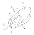
図1に示すように、第1実施形態に係る入力システム10は、メニュー画面、画像、メニュー画面を選択するポインタ12を表示する表示部14を有する表示装置11と、表示制御部25、データ送受信部26を有する装置本体と、画面に表示されているポインタ12の移動操作や、表示部14に表示されたメニュー画面から任意の項目を選択操作するための入力装置15と、一対のマーカ22A、22Bとで構成されている。Hereinafter, an input device according to an embodiment of the present invention will be described with reference to the drawings.
FIG. 1 is a system configuration diagram showing an input system according to the first embodiment of the present invention. FIG. 2 is a configuration diagram showing the configuration of the input device. FIG. 3 is a configuration diagram illustrating a configuration inside the housing of the input device.
As shown in FIG. 1, the input system 10 according to the first embodiment includes a
ポインタ12は、入力装置15の変位量に応じて、表示装置11の制御部25によって、表示部14上を移動させることができる。ポインタ12の動作は、制御部25で検出され、入力装置15の操作によりメニュー画面に表示された項目が選択されたことも検出することができる。 The
一対のマーカ22A,22Bは、一例として、赤外線21を含む光を表示装置11の前方に向かって出力するものである。 As an example, the pair of
次に入力装置15の構成について説明する。
入力装置15は、図2及び図3に示すように、外形が使用者の手で握りやすいように形成された筐体16と、筐体16の内部に収容された変位データ検出部(検出部)23、データ送受信部(送受信部)17、ジャイロ制御部(制御部)19およびジャイロ20、回路基板33、ジャイロ駆動用電池35、回路駆動用電池36を有し、筐体外部には、決定ボタン31、キャンセルボタン32、トリガボタン34を備えて構成されている。
なお、入力装置15は、例えば、PC用マウスのような有線のものや、TV用リモートコントローラのような無線のものが該当するものであり、第1実施形態においては、TV用リモートコントローラのような無線通信で行うものとして一例を例示する。Next, the configuration of the
As shown in FIGS. 2 and 3, the
The
データ送受信部27は、変位データ検出部23で検出した変位量を装置本体のデータ送受信部26に送信することができる。また、装置本体のデータ送受信部26から送信されたデータを受信することができるように構成されている。
撮像手段17は、マーカ22A、22Bを撮像すると共に、撮像結果を変位データ検出部23に送信するように構成されている。The data transmitter /
The imaging means 17 is configured to image the
ジャイロ制御部(制御部)19は、変位データ検出部23で検出した変位量に基づいてジャイロ20の回転体の回転速度や回転軸の回動軸の動作を制御することができるように構成されている。 The gyro control unit (control unit) 19 is configured to control the rotational speed of the rotating body of the
筐体16に収容された変位データ検出部(検出部)23は、一対のマーカ22A,22Bから出力された赤外線のみを撮像素子17で撮像して画像データを生成する。さらに、変位データ検出部(検出部)23は、生成した画像データに基づいて一対のマーカ22A,22Bの画像の変位から入力装置15の変位データを算出し、データ送受信部(送受信部)27に変位データを伝える。 The displacement data detection unit (detection unit) 23 housed in the
データ送受信部(送受信部)27は、変位データ検出部(検出部)23から伝えられた変位データをジャイロ制御部(制御部)19に伝えると共に、変位データを装置本体に無線送信する。また、使用者が決定ボタン31、キャンセルボタン32、トリガボタン34を押した際には、それらの入力データ(以下、単に「入力データ」という)を装置本体に送信する。 The data transmission / reception unit (transmission / reception unit) 27 transmits the displacement data transmitted from the displacement data detection unit (detection unit) 23 to the gyro control unit (control unit) 19 and wirelessly transmits the displacement data to the apparatus main body. When the user presses the
変位データとしては、変位速度や、変位方向、変位量がある。
具体的には、変位データは、以下のデータのうちいずれか1つ、または複数をいう。
・単位時間当たりの入力装置15の位置P(入力装置15の移動方向が判る)
・単位時間当たりの入力装置15の位置を基に算出した変位速度(入力装置15を振ったときの移動速度)V
・単位時間当たりの入力装置15の位置を基に算出した変位量SThe displacement data includes a displacement speed, a displacement direction, and a displacement amount.
Specifically, the displacement data refers to any one or more of the following data.
The position P of the
Displacement speed calculated based on the position of the
The displacement amount S calculated based on the position of the
入力装置15の位置P、変位速度V、変位量Sは、筐体16の内部に設けられたジャイロ制御部(制御部)19で演算され、後述のようにジャイロ20の制御に用いられる。 The position P, the displacement speed V, and the displacement amount S of the
装置本体は、データ送受信部26により、入力装置15から送信された変位データや入力データを受信し、受信されたデータは、表示制御部25に送られる。表示制御部25は、変位データや入力データに基づいて、メニュー画面やポインタの画像データを生成し、表示部14に送る。表示部14に送られたメニュー画面やポインタの画像データは、画像12として表示される。 The apparatus main body receives displacement data and input data transmitted from the
ジャイロ制御部19は、変位データ検出部23から伝えられた変位データ(位置P、変位速度V、変位量S)に基づいて、回転体43の回転速度または回転体43の回転軸44の向き(傾き)のうちの少なくとも一方を制御する信号をジャイロ20に伝えるものである。
回転軸44の向き(傾き)のデータとして、例えば、回転軸44の回動方向と回動角度、回動速度などが用いられる。
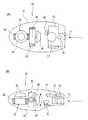
ジャイロ20は、ジャイロ制御部19から送られたデータに基づいて制御可能なモータ40と、モータ40に連結された回転軸44と、回転軸44に連結された回転体43と、回転体43およびモータ40を傾斜可能に支持する支持軸46と、支持軸46を軸にして回転体43およびモータ40を回動、傾斜させるモータ41とを備えている。モータ41もジャイロ制御部19から送られたデータに基づいて制御可能に構成されている。
このジャイロ20は、回転体43の回転軸44に対して直交する線45に沿う支持軸46を介して筐体16に支持されている。
入力装置15が変位した際には、ジャイロ制御部19から送られた信号(データ)に基づいてモータ41が駆動し、回転体43および回転軸44を支持軸46を軸にして矢印方向(図3(B)参照)に傾斜させることによりジャイロ効果によるトルクを発生させるものである。Based on the displacement data (position P, displacement speed V, displacement amount S) transmitted from the
As data of the direction (tilt) of the
The
The
When the
すなわち、ジャイロ20が回転軸44の向きを変えることで、ジャイロ効果により、入力装置の筐体の変位方向とは逆向きのトルクが発生し、使用者に変位方向に対する抵抗感として伝達されるため、直感的なフィードバックを与えることができる。 That is, because the
ここで、ジャイロ効果について簡単に説明する。図4において、Hをジャイロ回転体の角速度ベクトル、Ωをジャイロ回転軸の角速度ベクトル、Tをジャイロに生じるトルクベクトルとすると、H×Ω=T(式1)の関係が成り立つ。例えば、ジャイロ回転軸がZ軸回りのA方向(−Ω方向)に回動すると、ジャイロに生じるトルクは下向き(−T方向)となり、逆にジャイロがZ軸回りのB方向(Ω方向)に回動すると、ジャイロに生じるトルクは上向き(T方向)となる。 Here, the gyro effect will be briefly described. In FIG. 4, when H is an angular velocity vector of the gyro rotating body, Ω is an angular velocity vector of the gyro rotating shaft, and T is a torque vector generated in the gyro, a relationship of H × Ω = T (Expression 1) is established. For example, when the gyro rotation shaft rotates in the A direction (−Ω direction) around the Z axis, the torque generated in the gyro is downward (−T direction), and conversely, the gyro is in the B direction (Ω direction) around the Z axis. When rotating, the torque generated in the gyro is upward (T direction).
上記のジャイロを内蔵する入力装置の前方向をH方向と一致させ、入力装置の変位方向(A、B方向)を検知して、変位方向と逆向きのトルクが回転軸に発生するようにY軸(T方向)についてジャイロを所定角度回動させる制御を行えば、使用者には入力装置の変位方向とは逆向きの抵抗感が感じられる。 The front direction of the input device incorporating the above gyro is made to coincide with the H direction, the displacement direction (A, B direction) of the input device is detected, and the torque opposite to the displacement direction is generated on the rotating shaft. If the control for rotating the gyro by a predetermined angle about the axis (T direction) is performed, the user can feel a sense of resistance opposite to the displacement direction of the input device.
例えば、入力装置がA方向(−Ω方向)に変位したときには、ジャイロを下向き(−T方向)に回動させる制御を行う。また、入力装置がB方向(Ω方向)に変位したときには、ジャイロを上向き(T方向)に回動させる制御を行う。 For example, when the input device is displaced in the A direction (−Ω direction), the gyro is controlled to rotate downward (−T direction). Further, when the input device is displaced in the B direction (Ω direction), the gyro is controlled to rotate upward (T direction).
本実施形態では、使用者が入力装置を横方向にスイング操作した場合に、回転体43および回転軸44が支持軸46を軸にして縦方向(図3(B)の矢印方向)に回動制御される。ジャイロ効果によって、スイング方向と逆向きのトルクが発生し、使用者に抵抗感として伝達される。
このように、ジャイロ20の回転体43および回転軸44の向きを変動させることで、使用者は感覚的なフィードバックを得ることができる。In this embodiment, when the user swings the input device in the horizontal direction, the rotating
Thus, the user can obtain sensory feedback by changing the directions of the
なお、本実施形態の回転体43は、盤状に形成されたもので、モータ40の回転で回転するものである。
盤状の回転体43として、例えば、円盤や多角形のように回転軸44に対して軸対称な質量を有するものが該当する。その他の例としては、回転軸44に対して軸対称な質量を有していれば星形のようにスリットを有していても使用可能である。Note that the rotating
As the disk-shaped
なお、本実施形態では、一対のマーカ22A,22Bから発される赤外線を撮像し、この撮像画像の変位を基に入力装置の変位データを検出する例について説明したが、これに代えて、あるいはこれとともに加速度センサを筐体16に内蔵させ、加速度を基に入力装置の変位を検出することも可能である。
筐体16内部の加速度センサにより得られた加速度情報に基づいて、ジャイロ制御部19が回転体43を起動または回転速度を増速または回転軸44を傾斜させることも可能である。
この変形例によれば、より簡易な構成で、使用者は、筐体の操作に応じた直感的な(感覚的な)フィードバックを得ることができる。In the present embodiment, an example in which infrared rays emitted from the pair of
Based on the acceleration information obtained by the acceleration sensor inside the
According to this modification, the user can obtain intuitive (sensory) feedback according to the operation of the housing with a simpler configuration.
なお、入力装置15の変位速度や加速度を検知し、この変位速度や加速度に基づいて回転体43の回転速度または回転軸44の回動速度を制御してもよい。
入力装置15の変位速度が速い場合、あるいは加速度が大きい場合には、回転体43の回転速度または回転軸44の回動速度を速くする制御を行うことによって、変位速度に応じたより強い抵抗感が使用者に感じられる。
これにより、使用者は、筐体の操作に応じた直感的な(感覚的な)フィードバックを得ることができる。
なお、本実施形態では、入力装置と本体とが無線により変位データを送受信する例を挙げたが、有線により変位データを送受信しても差し支えない。この場合は、データ送受信部は不要となる。また、入力装置15の電源を装置本体から供給できるというメリットもある。The displacement speed and acceleration of the
When the displacement speed of the
Thereby, the user can obtain intuitive (sensory) feedback according to the operation of the housing.
In the present embodiment, an example in which the input device and the main body transmit and receive displacement data wirelessly has been described. However, the displacement data may be transmitted and received by wire. In this case, the data transmitter / receiver is not necessary. There is also an advantage that the power of the
(第2実施形態)
次に、表示装置11に表示された画像12を見ながら、入力装置15で入力操作や確認操作などを行い、画像の出力結果に基づいて入力装置内のジャイロを制御する実施形態を図1、図5に基づいて説明する。
図5(A),(B)に示すように、使用者が入力装置15を手47で握り、表示部14の画像12を見ながら、入力装置15を、スイング移動(スイング操作)や旋回移動(旋回操作)などをさせることにより入力操作を行う。例えば、画像12がメニュー画面である場合は、入力装置の変位に対し、ポインタが追従する動きをするように画像12の制御を行い、メニューの選択、決定等を行う。画像12がゲーム画面(例えばテニスゲーム)である場合は、入力装置の変位に、ゲーム画像中のプレーヤーが持つラケットの動きが追従するように画像12の制御を行う。(Second Embodiment)
Next, an embodiment in which an input operation or a confirmation operation is performed with the
As shown in FIGS. 5A and 5B, the user holds the
入力装置15の操作中に、図2に示す筐体16の変位データ検出部(検出部)23で、図1に示す一対のマーカ22A,22Bから出力された赤外線21のみを撮像素子17で撮像して画像データを生成する。
生成した画像データに基づいて一対のマーカ22A,22Bの変位を算出し、送受信部27に変位データを伝える。送受信部27から装置本体に送信された変位データは、データ送受信部26を経由して表示制御部25に送られる。During operation of the
Based on the generated image data, the displacement of the pair of
表示制御部25は、変位データに基づいて、表示部14に表示される画像12の画像データを生成する。
画像12がメニュー画面である場合、使用者が入力装置15を大きく動かすと、画像12の中のポインタが、入力装置の動きに追従して表示部14の表示領域外に飛び出してしまう可能性がある。このとき、表示制御部はポインタの位置と変位速度から、ポインタが表示部14の表示領域外に飛び出す可能性が高いと判断した場合には、ポインタの変位方向(入力装置15の変位方向)と逆の方向にトルクを発生させる制御データを生成する。例えば、入力装置15を大きく右側にスイング操作して、ポインタが表示部の右端に切れそうになった場合は、入力装置に左向きのトルクが発生するように、制御データを生成する。
画像12がテニスゲームの画面である場合、使用者が入力装置15を前方にスイング操作すると、ゲーム画像中のプレーヤーが持つラケットの動きが追従するように前方にスイングされる。そして、ゲーム画像中のラケットがボールにヒットする瞬間に、表示制御部はラケットの変位方向(入力装置15の変位方向)と逆の方向(後方)にトルクを発生させる制御データを生成する。The
When the
When the
この制御データが、データ送受信部26、27を経てジャイロ制御部19に伝えられる。ジャイロ制御部19は伝えられた制御データに基づいて、回転体43の回転軸44の向きを制御する信号をジャイロ20に伝える。 This control data is transmitted to the
ジャイロ20は、ジャイロ制御部19から送られたデータに基づいて、モータ41が駆動し、回転体43を支持軸46を軸にして矢印方向(図3(B)参照)に回動、傾斜させる。
回転体43を回動、傾斜させることでジャイロ効果により、入力装置15にトルクが発生する。The
By rotating and tilting the rotating
ここで、筐体16を速く・大きく動かす(変位させる)ほど、回転体の回転速度または回転軸の回動速度を大きくする制御を行ってもよい。この場合はジャイロ効果(数式1)によって筐体16を元に戻そうとするトルクが強く発生し、抵抗感が増す。 Here, the control may be performed to increase the rotational speed of the rotating body or the rotational speed of the rotating shaft as the
このように、入力装置15の変位データを基に生成された画像を表示装置に出力し、その画像データに基づいて、ジャイロの制御データを生成することにより、使用者が画像を目視で確認しながら、入力装置からフィードバックを得ることができる。したがって、例えば入力装置のスイング操作により、ポインタが表示部からはみ出そうとしたときに、入力装置の操作方向と逆向きのトルクを発生させることにより、ポインタを元に戻す方向にフィードバックを与えたり、ゲームの中でボールを打つシーンが登場したときに、使用者にあたかもボールを打ったような手応えが入力装置15を通じて感じられるように、入力装置15にトルクを発生させることができる。 In this way, the image generated based on the displacement data of the
つぎに、第2〜第5の実施形態を図6〜図9に基づいて説明する。なお、第2〜第5の実施形態において、第1実施形態の入力装置10と同一類似部材については同じ符号を付して説明を省略する。 Next, second to fifth embodiments will be described with reference to FIGS. In addition, in 2nd-5th embodiment, the same code | symbol is attached | subjected about the same similar member as the input device 10 of 1st Embodiment, and description is abbreviate | omitted.
(第3実施形態)
図6に示す第2実施形態のジャイロ50は、回転体43の回転軸44に対して直交する線に沿う第1支持軸52により筐体16に対して矢印A−B方向に回動自在に軸支され、かつ、ジャイロ50の重心が第1支持軸52の下方に設けられたもので、その構成は第1実施形態のジャイロ20と同じである。(Third embodiment)
A
ここで、回転体43のジャイロ効果によれば、回転体43の回転軸44方向が変位することにより、回転軸44の方向と回転軸44の変位方向の双方に直交する方向にトルクが発生する。 Here, according to the gyro effect of the
したがって、筐体16に回転軸44が固定された状態では、使用者の操作方向と直交する方向に筐体16を回動させようとするトルクが感じられ、使用者にとって直感的な操作感覚とはならない。
そこで、第2実施形態において、回転体43をトルクが発生する方向に対して回動自在となるように第1支持軸52を軸にして矢印A−B方向に回動自在に軸支することにした。Therefore, in a state in which the
Therefore, in the second embodiment, the
よって、例えば、回転体43を回転させた状態で、入力装置を図6の紙面左方向に移動した際に、回転体43が第1支持軸52を軸にして矢印A方向に回動する。
回転体43が矢印A方向に回動することで、回転体43に発生する下向きのトルクを使用者に伝達しないようにできる。
これにより、使用者には変位方向と直交する方向のトルクが感じられることなく、回転体43が回動するのに必要なエネルギーに相当する抵抗感F1のみが感じられる。Therefore, for example, when the input device is moved in the left direction in FIG. 6 with the
By rotating the
As a result, the user can feel only the resistance feeling F1 corresponding to the energy required for the
なお、回転体43は発生したトルクによって第1支持軸52の回りを矢印A方向に所定角度回動するが、ジャイロ50の重心位置を第1支持軸52の真下に設けているので、回動した後、ジャイロ50の自重によって元の位置に戻る。
これにより、使用者は、筐体16の操作に応じた直感的な(感覚的な)フィードバックF1を得ることができる。The rotating
Thereby, the user can obtain intuitive (sensory) feedback F1 according to the operation of the
一方、入力装置を図6の紙面右方向に移動した際に、回転体43が第1支持軸52を軸にして矢印B方向に回動する。
回転体43が矢印B方向に回動することで、回転体43に発生する上向きのトルクを使用者に伝達しないようにできる。
これにより、使用者には変位方向と直交する方向のトルクが感じられることなく、回転体43が回動するのに必要なエネルギーに相当する抵抗感F2のみが感じられる。On the other hand, when the input device is moved in the right direction in FIG. 6, the rotating
By rotating the
Thereby, the user can feel only the resistance feeling F2 corresponding to the energy required for the
なお、回転体43は発生したトルクによって第1支持軸52の回りを所定角度回動するが、ジャイロ50の重心位置を第1支持軸52の下方に設けているので、回動した後、ジャイロ50の自重によって元の位置に戻る。
これにより、使用者は、筐体16の操作に応じた直感的な(感覚的な)フィードバックF2を得ることができる。The rotating
Thereby, the user can obtain intuitive (sensory) feedback F <b> 2 according to the operation of the
本実施形態によれば、第1実施形態と異なり、回転体43および回転軸44の向きを制御することはしないため、使用者に感じられる抵抗感は第1実施形態と比較すると小さなものとなる。しかし、回転軸44を回動するモータが不要となることから入力装置を小型化、軽量化することができ、消費電力も抑えられるというメリットがある。 According to the present embodiment, unlike the first embodiment, the orientation of the
(第4実施形態)
図7に示す第4実施形態のジャイロ60は、筐体に1個のジャイロを二軸支持としたもので、二つの支持軸について各々ジャイロを回動させるモータを有している。その他の構成は第1実施形態のジャイロ20と同じである。(Fourth embodiment)
A
すなわち、ジャイロ60は、回転体61の回転軸62に対して直交する線63に沿う第1支持軸65と、第1支持軸65を支持する枠部66と、枠部66と筐体16(図2参照)との間に介装され、回転軸62と第1支持軸63に対して直交する線67に沿う第2支持軸68とを有する。 That is, the
よって、第3実施形態のジャイロ60によれば、第1支持軸66および第2支持軸68に連結されたモータによって回転体61および回転軸62の方向を回動制御することにより、使用者がコントローラのスイング操作を上下方向、左右方向いずれに行っても、スイング方向と逆向きのトルクを発生させ、使用者に抵抗感を与えることができる。したがって、使用者に直感的なフィードバックを与えることができる。 Therefore, according to the
(第5実施形態)
図8に示す第5実施形態のジャイロ70は、回転軸44および支持軸46の向きが直交する複数(2個)のジャイロを備えたもので、その他の構成は第1実施形態と同じである。(Fifth embodiment)
The
ジャイロ70は、通常、2個のジャイロの回転体43は停止または低速回転に保たれている。筐体16を移動させたときに特定のジャイロの回転体43を起動または高速回転に変える。
なお、2個のジャイロの支持軸46の向きは変わらない。In the
The directions of the
よって、第5実施形態のジャイロ70によれば、2つのジャイロを使い分けることや、併用することが可能である。
なお、2個のジャイロに備えた各回転体43の回転速度の制御も併用することが可能である。Therefore, according to the
In addition, control of the rotational speed of each
(第6実施形態)
図9に示す第6実施形態のジャイロ80は、回転軸81の向きが3軸方向に直交する3つのモータ82で球状のジャイロ83を回転駆動可能に構成したもので、その構成は第1実施形態と同じである。(Sixth embodiment)
A
球状の回転体83は、支持リング84に等間隔に配置された3個の回転体85に支えられている。回転体85は回転軸81に連結されている。また、ジャイロ83は半球状のカバー87で保持されている。 The spherical
ジャイロ80は、通常、ジャイロ83は停止または低速回転に保たれている。そして、筐体16を移動させたときに特定のモータ82(最大2個、3個は不可)を起動または高速回転に変えることにより、回転体83を3軸方向に任意速度で回転させることができる。
なお、ジャイロ83の回転速度の制御も併用することが可能である。In the
Note that the control of the rotational speed of the
よって、第5実施形態のジャイロ80によれば、前述した各実施形態と同様な効果が得られる。 Therefore, according to the
本発明は、筐体内の回転体を回転することにより応力を発生させて使用者に抵抗感が感じられるようにした入力装置および入力システムへの適用に好適である。 INDUSTRIAL APPLICABILITY The present invention is suitable for application to an input device and an input system in which stress is generated by rotating a rotating body in a housing so that a user can feel resistance.
10 入力システム
11 表示装置
15 入力装置
16 筐体
19 ジャイロ制御部(制御部)
20,50,60,70,80 ジャイロ
22 データ送受信部(送受信部)
23 変位データ検出部(検出部)
27 データ送受信部(送受信部)
43,61 回転体
44,62 回転軸
45,63 回転軸に対して直交する線
46 支持軸
52,65 第1支持軸
66 枠部
67 第1支持軸に対して直交する線
68 第2支持軸DESCRIPTION OF SYMBOLS 10
20, 50, 60, 70, 80
23 Displacement data detector (detector)
27 Data transmission / reception unit (transmission / reception unit)
43, 61
Claims (8)
Translated fromJapanese前記筐体に収容され、回転軸に対して軸対称な質量を有する回転体を備えたジャイロと、
前記回転体の回転軸を回動させる回動手段と、
前記筐体の変位方向および変位量を検出する変位検出手段と、
前記変位検出手段の検出結果に基づいて前記回動手段を制御する制御手段と、
を備えることを特徴とする入力装置。A housing,
A gyro including a rotating body housed in the housing and having a mass axisymmetric with respect to a rotation axis;
A rotating means for rotating the rotating shaft of the rotating body;
Displacement detecting means for detecting a displacement direction and a displacement amount of the housing;
Control means for controlling the rotation means based on the detection result of the displacement detection means;
An input device comprising:
前記筐体に収容され、回動可能な回転軸と、この回転軸に対して軸対称な質量を有する回転体とを備えたジャイロを備え、
前記ジャイロは、前記回転体の回転軸に対して直交する線に沿う第1支持軸により前記筐体に対して回動自在に軸支され、前記ジャイロの重心は第1支持軸の下方に設けられていることを特徴とする入力装置。A housing,
A gyro that is housed in the housing and includes a rotatable rotating shaft and a rotating body having an axisymmetric mass with respect to the rotating shaft;
The gyro is pivotally supported with respect to the housing by a first support shaft along a line orthogonal to the rotation axis of the rotating body, and the center of gravity of the gyro is provided below the first support shaft. An input device characterized by that.
前記装置本体は、
前記変位検出手段の検出結果を受信する受信手段と、
前記受信手段で受信した検出結果に基づいて画像を生成する画像生成手段と、
前記画像生成手段からの出力結果を前記入力装置に送信する送信手段とを備え、前記入力装置の操作に基づいて、前記画像出力手段から画像出力すると共に、前記画像出力の出力結果に基づいて前記ジャイロを制御することを特徴とする入力操作システム。An input operation system comprising the input device according to any one of claims 1 to 7 and a device main body that receives input information from the input device,
The device body is
Receiving means for receiving a detection result of the displacement detecting means;
Image generating means for generating an image based on the detection result received by the receiving means;
A transmission unit that transmits an output result from the image generation unit to the input device, and outputs an image from the image output unit based on an operation of the input device, and the output based on the output result of the image output. An input operation system characterized by controlling a gyro.
Priority Applications (1)
| Application Number | Priority Date | Filing Date | Title |
|---|---|---|---|
| JP2007244200AJP2009075861A (en) | 2007-09-20 | 2007-09-20 | Input device and input system |
Applications Claiming Priority (1)
| Application Number | Priority Date | Filing Date | Title |
|---|---|---|---|
| JP2007244200AJP2009075861A (en) | 2007-09-20 | 2007-09-20 | Input device and input system |
Publications (1)
| Publication Number | Publication Date |
|---|---|
| JP2009075861Atrue JP2009075861A (en) | 2009-04-09 |
Family
ID=40610766
Family Applications (1)
| Application Number | Title | Priority Date | Filing Date |
|---|---|---|---|
| JP2007244200AWithdrawnJP2009075861A (en) | 2007-09-20 | 2007-09-20 | Input device and input system |
Country Status (1)
| Country | Link |
|---|---|
| JP (1) | JP2009075861A (en) |
Cited By (8)
| Publication number | Priority date | Publication date | Assignee | Title |
|---|---|---|---|---|
| JP2011244965A (en)* | 2010-05-25 | 2011-12-08 | Nintendo Co Ltd | Information processing program, information processing apparatus, information processing method and information processing system |
| WO2012132495A1 (en)* | 2011-03-30 | 2012-10-04 | 本田技研工業株式会社 | Operation device |
| JP2017000759A (en)* | 2015-06-12 | 2017-01-05 | 任天堂株式会社 | Game controller |
| JP2020204951A (en)* | 2019-06-18 | 2020-12-24 | アルプスアルパイン株式会社 | Force sense generating apparatus |
| JP2021060896A (en)* | 2019-10-09 | 2021-04-15 | アルプスアルパイン株式会社 | Force-sense generating device |
| JP2022529322A (en)* | 2019-04-18 | 2022-06-21 | コーニンクレッカ フィリップス エヌ ヴェ | Systems and methods that provide adaptive physical feedback to users of handheld devices |
| WO2024090137A1 (en)* | 2022-10-27 | 2024-05-02 | オムロン株式会社 | Operating device |
| JP2024140894A (en)* | 2023-03-28 | 2024-10-10 | Kddi株式会社 | Motion support program, device, and method using gyro moment, and force feedback device |
- 2007
- 2007-09-20JPJP2007244200Apatent/JP2009075861A/ennot_activeWithdrawn
Cited By (13)
| Publication number | Priority date | Publication date | Assignee | Title |
|---|---|---|---|---|
| US9492747B2 (en) | 2010-05-25 | 2016-11-15 | Nintendo Co., Ltd. | Using handheld controller attitude to select a desired object displayed on a screen |
| JP2011244965A (en)* | 2010-05-25 | 2011-12-08 | Nintendo Co Ltd | Information processing program, information processing apparatus, information processing method and information processing system |
| WO2012132495A1 (en)* | 2011-03-30 | 2012-10-04 | 本田技研工業株式会社 | Operation device |
| CN103314342A (en)* | 2011-03-30 | 2013-09-18 | 本田技研工业株式会社 | operating device |
| JP5563153B2 (en)* | 2011-03-30 | 2014-07-30 | 本田技研工業株式会社 | Operating device |
| JP2017000759A (en)* | 2015-06-12 | 2017-01-05 | 任天堂株式会社 | Game controller |
| JP2022529322A (en)* | 2019-04-18 | 2022-06-21 | コーニンクレッカ フィリップス エヌ ヴェ | Systems and methods that provide adaptive physical feedback to users of handheld devices |
| JP7643343B2 (en) | 2019-04-18 | 2025-03-11 | コーニンクレッカ フィリップス エヌ ヴェ | SYSTEM AND METHOD FOR PROVIDING ADAPTIVE PHYSICAL FEEDBACK TO A USER OF A HANDHELD DEVICE - Patent application |
| JP2020204951A (en)* | 2019-06-18 | 2020-12-24 | アルプスアルパイン株式会社 | Force sense generating apparatus |
| JP7344742B2 (en) | 2019-10-09 | 2023-09-14 | アルプスアルパイン株式会社 | Force sensation generation device |
| JP2021060896A (en)* | 2019-10-09 | 2021-04-15 | アルプスアルパイン株式会社 | Force-sense generating device |
| WO2024090137A1 (en)* | 2022-10-27 | 2024-05-02 | オムロン株式会社 | Operating device |
| JP2024140894A (en)* | 2023-03-28 | 2024-10-10 | Kddi株式会社 | Motion support program, device, and method using gyro moment, and force feedback device |
Similar Documents
| Publication | Publication Date | Title |
|---|---|---|
| JP2009075861A (en) | Input device and input system | |
| KR101169813B1 (en) | Game system and storage medium having game program stored thereon | |
| JP5996138B1 (en) | GAME PROGRAM, METHOD, AND GAME SYSTEM | |
| US8708822B2 (en) | Information processing system and program | |
| JP5037077B2 (en) | PROGRAM, INFORMATION STORAGE MEDIUM, AND GAME DEVICE | |
| US9457861B2 (en) | Inverted pendulum type vehicle | |
| KR20070025962A (en) | Information Processing Systems and Programs | |
| US20100022300A1 (en) | Device with spatially unrestricted force feedback | |
| US10310602B2 (en) | Controlled gyroscopic torque for an electronic device | |
| JP5358168B2 (en) | GAME DEVICE AND GAME PROGRAM | |
| JP5294554B2 (en) | GAME PROGRAM, GAME DEVICE, GAME SYSTEM, AND GAME PROCESSING METHOD | |
| JP2013078624A (en) | Game system and game program | |
| JP6684746B2 (en) | Information processing method, computer and program | |
| JP5945297B2 (en) | GAME PROGRAM AND GAME DEVICE | |
| JP2010142404A (en) | Game program, and game apparatus | |
| JP5920861B2 (en) | Control device, control method and program | |
| JP6535641B2 (en) | Method and apparatus for controlling an object displayed in a virtual space, and program for causing a computer to execute the method | |
| JP2008281659A (en) | Display device and game device | |
| JP5973788B2 (en) | Information processing program, information processing apparatus, information processing system, and information processing method | |
| JP7373147B2 (en) | game system | |
| JP2017099608A (en) | Control system and program | |
| JP6893532B2 (en) | Information processing methods, computers and programs | |
| JP5339490B2 (en) | GAME DEVICE AND GAME PROGRAM | |
| JP5006253B2 (en) | Input device | |
| JP2017170106A (en) | Game program, method, and game system |
Legal Events
| Date | Code | Title | Description |
|---|---|---|---|
| A300 | Application deemed to be withdrawn because no request for examination was validly filed | Free format text:JAPANESE INTERMEDIATE CODE: A300 Effective date:20101207 |