JP2009075112A - Analytical system for measuring analytes in body fluids - Google Patents
Analytical system for measuring analytes in body fluidsDownload PDFInfo
- Publication number
- JP2009075112A JP2009075112AJP2008241193AJP2008241193AJP2009075112AJP 2009075112 AJP2009075112 AJP 2009075112AJP 2008241193 AJP2008241193 AJP 2008241193AJP 2008241193 AJP2008241193 AJP 2008241193AJP 2009075112 AJP2009075112 AJP 2009075112A
- Authority
- JP
- Japan
- Prior art keywords
- analysis
- measurement
- control data
- data values
- analysis system
- Prior art date
- Legal status (The legal status is an assumption and is not a legal conclusion. Google has not performed a legal analysis and makes no representation as to the accuracy of the status listed.)
- Granted
Links
- 210000001124body fluidAnatomy0.000titleclaimsabstractdescription12
- 239000010839body fluidSubstances0.000titleclaimsabstractdescription11
- 238000004458analytical methodMethods0.000claimsabstractdescription169
- 238000005259measurementMethods0.000claimsabstractdescription148
- 238000011156evaluationMethods0.000claimsabstractdescription67
- 238000012360testing methodMethods0.000claimsabstractdescription35
- 238000012545processingMethods0.000claimsabstractdescription29
- 230000008859changeEffects0.000claimsabstractdescription16
- 239000012491analyteSubstances0.000claimsabstractdescription11
- 239000003153chemical reaction reagentSubstances0.000claimsabstractdescription9
- 238000006243chemical reactionMethods0.000claimsabstractdescription7
- 230000003287optical effectEffects0.000claimsdescription43
- 239000004020conductorSubstances0.000claimsdescription11
- 239000013307optical fiberSubstances0.000claimsdescription9
- 230000001678irradiating effectEffects0.000claimsdescription2
- WQZGKKKJIJFFOK-GASJEMHNSA-NGlucoseNatural productsOC[C@H]1OC(O)[C@H](O)[C@@H](O)[C@@H]1OWQZGKKKJIJFFOK-GASJEMHNSA-N0.000description7
- 239000008103glucoseSubstances0.000description7
- NOESYZHRGYRDHS-UHFFFAOYSA-NinsulinChemical compoundN1C(=O)C(NC(=O)C(CCC(N)=O)NC(=O)C(CCC(O)=O)NC(=O)C(C(C)C)NC(=O)C(NC(=O)CN)C(C)CC)CSSCC(C(NC(CO)C(=O)NC(CC(C)C)C(=O)NC(CC=2C=CC(O)=CC=2)C(=O)NC(CCC(N)=O)C(=O)NC(CC(C)C)C(=O)NC(CCC(O)=O)C(=O)NC(CC(N)=O)C(=O)NC(CC=2C=CC(O)=CC=2)C(=O)NC(CSSCC(NC(=O)C(C(C)C)NC(=O)C(CC(C)C)NC(=O)C(CC=2C=CC(O)=CC=2)NC(=O)C(CC(C)C)NC(=O)C(C)NC(=O)C(CCC(O)=O)NC(=O)C(C(C)C)NC(=O)C(CC(C)C)NC(=O)C(CC=2NC=NC=2)NC(=O)C(CO)NC(=O)CNC2=O)C(=O)NCC(=O)NC(CCC(O)=O)C(=O)NC(CCCNC(N)=N)C(=O)NCC(=O)NC(CC=3C=CC=CC=3)C(=O)NC(CC=3C=CC=CC=3)C(=O)NC(CC=3C=CC(O)=CC=3)C(=O)NC(C(C)O)C(=O)N3C(CCC3)C(=O)NC(CCCCN)C(=O)NC(C)C(O)=O)C(=O)NC(CC(N)=O)C(O)=O)=O)NC(=O)C(C(C)CC)NC(=O)C(CO)NC(=O)C(C(C)O)NC(=O)C1CSSCC2NC(=O)C(CC(C)C)NC(=O)C(NC(=O)C(CCC(N)=O)NC(=O)C(CC(N)=O)NC(=O)C(NC(=O)C(N)CC=1C=CC=CC=1)C(C)C)CC1=CN=CN1NOESYZHRGYRDHS-UHFFFAOYSA-N0.000description6
- 239000008280bloodSubstances0.000description5
- 210000004369bloodAnatomy0.000description5
- 238000010586diagramMethods0.000description5
- 230000008901benefitEffects0.000description4
- 102000004877InsulinHuman genes0.000description3
- 108090001061InsulinProteins0.000description3
- 238000001514detection methodMethods0.000description3
- 238000002848electrochemical methodMethods0.000description3
- 238000007689inspectionMethods0.000description3
- 229940125396insulinDrugs0.000description3
- 239000007788liquidSubstances0.000description3
- 238000012544monitoring processMethods0.000description3
- 238000003908quality control methodMethods0.000description3
- 230000005540biological transmissionEffects0.000description2
- HVYWMOMLDIMFJA-DPAQBDIFSA-NcholesterolChemical compoundC1C=C2C[C@@H](O)CC[C@]2(C)[C@@H]2[C@@H]1[C@@H]1CC[C@H]([C@H](C)CCCC(C)C)[C@@]1(C)CC2HVYWMOMLDIMFJA-DPAQBDIFSA-N0.000description2
- 238000000840electrochemical analysisMethods0.000description2
- 238000005516engineering processMethods0.000description2
- 238000000034methodMethods0.000description2
- 230000010287polarizationEffects0.000description2
- 239000000969carrierSubstances0.000description1
- 235000012000cholesterolNutrition0.000description1
- 239000011248coating agentSubstances0.000description1
- 238000000576coating methodMethods0.000description1
- 230000000052comparative effectEffects0.000description1
- 239000002131composite materialSubstances0.000description1
- 230000001419dependent effectEffects0.000description1
- 238000013461designMethods0.000description1
- 230000000694effectsEffects0.000description1
- 238000003487electrochemical reactionMethods0.000description1
- 239000003365glass fiberSubstances0.000description1
- 230000036541healthEffects0.000description1
- 238000002847impedance measurementMethods0.000description1
- 238000004020luminiscence typeMethods0.000description1
- 230000007257malfunctionEffects0.000description1
- 238000004519manufacturing processMethods0.000description1
- 238000005375photometryMethods0.000description1
- 229920000642polymerPolymers0.000description1
- 230000008569processEffects0.000description1
- 230000004044responseEffects0.000description1
- 230000001052transient effectEffects0.000description1
- 238000010200validation analysisMethods0.000description1
- 238000009736wettingMethods0.000description1
Images


Classifications
- G—PHYSICS
- G01—MEASURING; TESTING
- G01N—INVESTIGATING OR ANALYSING MATERIALS BY DETERMINING THEIR CHEMICAL OR PHYSICAL PROPERTIES
- G01N33/00—Investigating or analysing materials by specific methods not covered by groups G01N1/00 - G01N31/00
- G01N33/48—Biological material, e.g. blood, urine; Haemocytometers
- G01N33/483—Physical analysis of biological material
- G01N33/487—Physical analysis of biological material of liquid biological material
- G01N33/48785—Electrical and electronic details of measuring devices for physical analysis of liquid biological material not specific to a particular test method, e.g. user interface or power supply
- G01N33/48792—Data management, e.g. communication with processing unit
- G—PHYSICS
- G01—MEASURING; TESTING
- G01N—INVESTIGATING OR ANALYSING MATERIALS BY DETERMINING THEIR CHEMICAL OR PHYSICAL PROPERTIES
- G01N21/00—Investigating or analysing materials by the use of optical means, i.e. using sub-millimetre waves, infrared, visible or ultraviolet light
- G01N21/75—Systems in which material is subjected to a chemical reaction, the progress or the result of the reaction being investigated
- G01N21/77—Systems in which material is subjected to a chemical reaction, the progress or the result of the reaction being investigated by observing the effect on a chemical indicator
- G01N21/78—Systems in which material is subjected to a chemical reaction, the progress or the result of the reaction being investigated by observing the effect on a chemical indicator producing a change of colour
- G—PHYSICS
- G01—MEASURING; TESTING
- G01N—INVESTIGATING OR ANALYSING MATERIALS BY DETERMINING THEIR CHEMICAL OR PHYSICAL PROPERTIES
- G01N21/00—Investigating or analysing materials by the use of optical means, i.e. using sub-millimetre waves, infrared, visible or ultraviolet light
- G01N21/84—Systems specially adapted for particular applications
- G01N21/8483—Investigating reagent band
Landscapes
- Health & Medical Sciences (AREA)
- Engineering & Computer Science (AREA)
- Physics & Mathematics (AREA)
- Life Sciences & Earth Sciences (AREA)
- Chemical & Material Sciences (AREA)
- Biomedical Technology (AREA)
- Biophysics (AREA)
- Analytical Chemistry (AREA)
- Biochemistry (AREA)
- General Health & Medical Sciences (AREA)
- General Physics & Mathematics (AREA)
- Immunology (AREA)
- Pathology (AREA)
- Human Computer Interaction (AREA)
- Molecular Biology (AREA)
- Optics & Photonics (AREA)
- Databases & Information Systems (AREA)
- Chemical Kinetics & Catalysis (AREA)
- Plasma & Fusion (AREA)
- Hematology (AREA)
- Medical Informatics (AREA)
- Urology & Nephrology (AREA)
- Food Science & Technology (AREA)
- Medicinal Chemistry (AREA)
- Investigating Or Analysing Materials By Optical Means (AREA)
- Automatic Analysis And Handling Materials Therefor (AREA)
- Investigating Or Analysing Biological Materials (AREA)
Abstract
Translated fromJapaneseDescription
Translated fromJapanese本発明は、被分析物との反応が、所望の分析結果を特徴付ける検出可能な変化を生じる試薬システムを含むテストエレメント、および測定・評価ユニットを備える分析装置を有する、体液の被分析物を測定するための分析システムに関する。 The present invention measures an analyte in a body fluid having a test element that includes a reagent system whose reaction with the analyte produces a detectable change that characterizes the desired analytical result, and an analyzer with a measurement and evaluation unit. It is related with the analysis system for doing.
使い捨てのテストエレメント、試験担体または試験片を用いる体液の被分析物を測定するための分析システムは、先行技術において周知である。この種のシステムは、種々の被分析物の濃度を測定するために用いられる。たとえば、血中のグルコース濃度またはコレステロール濃度が測定される。 Analytical systems for measuring body fluid analytes using disposable test elements, test carriers or test strips are well known in the prior art. This type of system is used to measure the concentration of various analytes. For example, blood glucose concentration or cholesterol concentration is measured.
テストエレメントは、一般に、液体試料との反応が、分析システムを用いて測定することができる、検出可能な変化を生じる1以上の試薬から成る試薬システムを含む。測光分析システムにおいては、テストエレメントが試料と反応したとき、テストエレメントの検出層に色の変化が生じるが、それは、分析システムに付属の測定・評価ユニットを用いて光度測定が行なわれる。たとえば、テストエレメントによって反射された光の強さが測定される。 A test element generally comprises a reagent system consisting of one or more reagents that produce a detectable change that can be measured using a analytical system. In the photometric analysis system, when the test element reacts with the sample, a color change occurs in the detection layer of the test element. This is measured by using a measurement / evaluation unit attached to the analysis system. For example, the intensity of light reflected by the test element is measured.
代替として、所謂電気化学分析システムも用いることができるが、この場合、液体試料をテストエレメントに供給したとき電気化学反応が生じ、それは、検出可能な荷電量の変化、電流、または電圧変化として検出される。 Alternatively, so-called electrochemical analysis systems can also be used, in which case an electrochemical reaction occurs when a liquid sample is supplied to the test element, which is detected as a change in detectable charge, current or voltage change. Is done.
公知の分析システムは、適切に使用されたとき、高い信頼性が得られるように動作する。しかし、誤った測定結果が、分析機器の誤動作またはテストエレメントの誤った使用によってもたらされることがある。充分な注意がそのような分析システムとテストエレメントの作製には払われているが、誤った結果を出力することを回避するために、測定装置の故障が判定できる程の高い品質管理が望まれる。 Known analytical systems operate to provide high reliability when used properly. However, erroneous measurement results may be caused by analytical instrument malfunction or incorrect use of test elements. Although sufficient attention is paid to the production of such analysis systems and test elements, high quality control is required so that the failure of the measuring device can be determined in order to avoid outputting erroneous results. .
とりわけ血中グルコース濃度が測定されるグルコース測定システムについては、高い信頼性と低い許容誤差であることが求められる。血中グルコース濃度の濃度測定の結果は、患者の治療の基礎となる。インスリンの投与は、測定したグルコース濃度によって決められるために、誤りのない分析値が重要になる。誤った測定結果に基づく、よってインスリンの誤った(低すぎるまたは高すぎるインスリン量の)投与が行なわれる患者の治療は、健康並びに生命に危害を与える可能性がある。 In particular, a glucose measurement system that measures blood glucose concentration is required to have high reliability and low tolerance. The result of the concentration measurement of the blood glucose concentration is the basis for the treatment of the patient. Since the administration of insulin is determined by the measured glucose concentration, an error-free analytical value becomes important. Treatment of patients based on erroneous measurement results, and thus incorrect administration of insulin (too low or too high amount of insulin), can be harmful to health as well as life.
このために、重複システムが用いられ、その場合、分析領域からの反射光を測定する、たとえば2つの光度検出器が並列に配置される。この種のシステムは、米国特許第6955060号明細書に記載されている。代替として、1つの検出器を用いて2つの異なる分析結果を得るために、2つの光源により2つの分離した分析領域を照射することもできる。 For this purpose, an overlapping system is used, in which case, for example, two photometric detectors measuring the reflected light from the analysis region are arranged in parallel. This type of system is described in US Pat. No. 6,955,060. Alternatively, two separate analysis regions can be illuminated by two light sources in order to obtain two different analysis results using a single detector.
分析システムのエラーは、一般に機械的、測定技術の、または電子機器のレベルにおいて影響を及ぼす。デジタル・サブシステムそのものは、充分にモニター可能であるが、デジタル・アナログ部分系においては、測定の精度および/または正確度を確保するための品質管理は、かなり困難なものになる。 Analytical system errors generally affect mechanical, measurement technology, or electronics levels. Although the digital subsystem itself can be monitored sufficiently, in the digital / analog subsystem, quality control to ensure measurement accuracy and / or accuracy becomes quite difficult.
測定精度を向上させるとともに、特にエラーを回避するために、互いに独立した複数回の測定を患者が実施するようにもできる。たとえば、ユーザに、同一の装置、ただし2つの異なるテストエレメントを用いて2つの独立した測定を連続して実施するようにさせることもできる。しかし、この種の作業を実際にユーザに求めることは適当ではない。 In order to improve the measurement accuracy and in particular to avoid errors, it is also possible for the patient to carry out a plurality of independent measurements. For example, the user can be made to perform two independent measurements in succession using the same device, but two different test elements. However, it is not appropriate to actually ask the user for this kind of work.
代替として、測定の信頼性を向上させるために、測定を、互いに完全に独立した2つの装置を用いて実施することもできる。この方法も、また、測定の手間とコストが大きく増大するために、現実的ではない。 As an alternative, in order to improve the reliability of the measurement, the measurement can also be carried out using two devices that are completely independent of each other. This method is also not practical due to the great increase in measurement effort and cost.
従って、本発明は、信頼性を向上させるために、公知の分析システムを改良することを目的とする。 Therefore, an object of the present invention is to improve a known analysis system in order to improve reliability.
この目的は、請求項1記載の特徴を有する分析システムによって達成される。本発明による分析システムの、従属請求項に記載のさらなる改良項目が、その他の有利な、非自明の特徴を規定する。 This object is achieved by an analysis system having the features of claim 1. Further refinements of the analysis system according to the invention, as defined in the dependent claims, define other advantageous, non-obvious features.
本発明による、体液の被分析物を測定する分析システムは、被分析物との反応が、所望の分析結果を特徴付ける検出可能な変化を生じる試薬システムを備えるテストエレメントを有する。テストエレメントは、試料塗布領域と2つの分析領域を有する。分析システムは、測定・評価ユニットを備える分析装置を有する。該ユニットは、1つの分析領域における変化に相当するアナログ測定信号がその各々において生成される(少なくとも)2つのアナログ測定ユニット、アナログ測定信号をデジタル化するための2つのデジタル・アナログ変換器、デジタル化測定信号に基づいて制御データ値を比較する比較器、および最終処理ユニットを有する。デジタル化測定信号の比較制御データ値間の測定偏差が予め規定された値より小さい場合、制御データ値の少なくとも1つが最終処理ユニットにおいて有効にされ、また、所望の分析結果を得るために、有効になった制御データ値がさらに処理される。 An analysis system for measuring an analyte in a bodily fluid according to the present invention has a test element with a reagent system whose reaction with the analyte produces a detectable change that characterizes the desired analysis result. The test element has a sample application area and two analysis areas. The analysis system includes an analysis device including a measurement / evaluation unit. The unit comprises (at least) two analog measurement units, each of which generates an analog measurement signal corresponding to a change in one analysis region, two digital-to-analog converters for digitizing the analog measurement signal, digital A comparator for comparing the control data values based on the measurement signal and a final processing unit. If the measurement deviation between the comparative control data values of the digitized measurement signal is smaller than a predefined value, at least one of the control data values is validated in the final processing unit and valid for obtaining the desired analysis result The resulting control data value is further processed.
本発明の用語の意味について説明すると、アナログ測定に相当する信号とは、測定信号の値が分析領域における変化についての測定値であると理解される。測定信号は、変化に比例していてもよいが、このことは厳格な数学的意味において理解されるべきものではなく、被分析物濃度と測定信号の間の典型的な非線形の関係も含むものとする。 When the meaning of the terminology of the present invention is described, a signal corresponding to an analog measurement is understood to be a measurement value for a change in the value of the measurement signal in the analysis region. The measurement signal may be proportional to the change, but this is not to be understood in a strict mathematical sense and should also include a typical non-linear relationship between the analyte concentration and the measurement signal. .
本発明においては、エラーの影響が、機械的レベルまたは測定技術レベル、並びに、たとえば所謂ビットフリップの形態で電子的レベルの両方において発生する可能性があるために、分析領域、アナログ測定ユニットおよびアナログ・デジタル変換器を重複して有する総合的な評価チャネルを設計することが、とりわけ重要であることが判った。先行技術において、分析システムのデジタル成分を、たとえばソフトウェアのアルゴリズムによるチェックを介してモニターする実施形態は公知であるが、デジタル・アナログ複合系または部分系をモニタリングすることは、大きい困難を伴う。この困難は、測定チャネルを重複構成することによって解決された。代替として、2つの評価チャネルだけではなく、重複した3つ以上の評価チャネルを設けることもできる。 In the present invention, the effects of errors can occur both at the mechanical or measurement technology level and at the electronic level, for example in the form of so-called bit flips, so that the analysis area, analog measurement unit and analog It has been found that it is particularly important to design a comprehensive evaluation channel with overlapping digital converters. In the prior art, embodiments are known in which the digital components of an analytical system are monitored, for example via checking by software algorithms, but monitoring digital-analog composites or subsystems is very difficult. This difficulty was solved by overlapping the measurement channels. Alternatively, not only two evaluation channels but also three or more overlapping evaluation channels can be provided.
本発明によると、分析システムは、2つの互いに独立した測定が平行して行なわれるように、重複構成されている。2つの分析領域の各々には、アナログ測定ユニットとアナログ・デジタル変換器が設けられており、分析領域における変化に比例するおよび/または変化の測定値であるアナログ測定信号が、アナログ測定ユニットにおいて生成される。アナログ・デジタル変換器を有するデジタル・ユニットは、アナログ測定ユニットからの測定信号をデジタル化する。分析システムは、このように、互いに独立して動作する2つの評価チャネルを有し、評価チャネルは、アナログ測定ユニットだけでなく、アナログ・デジタル変換器として実施されたデジタル・ユニットも有する。両方の測定は、互いに完全に独立して実施され、同時並行の実施も可能である。分析システムは、きわめて確実で信頼性の高い結果を提示する。ユーザは並行測定に気付かないために、システムのユーザにとっての使い易さは非常に高い。1つの評価チャネルで発生した測定エラーは、直ちに認識される。この種の分析システムは、とりわけグルコースの測定に好適であるが、それは、非常に低い許容誤差、非常に高い品質管理および確実な分析結果が求められるからである。 According to the invention, the analysis system is configured in an overlapping manner so that two independent measurements are made in parallel. Each of the two analysis areas is provided with an analog measurement unit and an analog-to-digital converter, and an analog measurement signal is generated in the analog measurement unit that is proportional to and / or a measurement of the change in the analysis area Is done. A digital unit having an analog-to-digital converter digitizes the measurement signal from the analog measurement unit. The analysis system thus has two evaluation channels that operate independently of each other, and the evaluation channel has not only an analog measurement unit, but also a digital unit implemented as an analog-to-digital converter. Both measurements are performed completely independently of each other and can be performed concurrently. The analytical system presents extremely reliable and reliable results. Since the user is not aware of the parallel measurement, the ease of use for the user of the system is very high. Measurement errors that occur in one evaluation channel are immediately recognized. This type of analysis system is particularly suitable for the measurement of glucose, since very low tolerances, very high quality control and reliable analytical results are required.
この目的に必要なことは、2つの異なる分析領域を用いることである。分析領域の用語は、面積だけでなく、分析容積および/または評価容積も含むと了解されるものとし、このことは、分析領域は、三次元であることを意味する。従って、2つの分析領域は、同一のサイズであっても、互いに空間的に対応させたときの容積は異なる。2つの分析領域の重複および/または両領域が共有する部分的容積または部分的量は、まったく可能なことである。2つの分析領域は同一である必要はないが、そうでない場合には、得られた測定結果の量が減少する。 What is needed for this purpose is the use of two different analysis areas. The term analysis region shall be understood to include not only the area but also the analysis volume and / or the evaluation volume, which means that the analysis region is three-dimensional. Therefore, even when the two analysis regions have the same size, the volumes when spatially corresponding to each other are different. The overlap of the two analysis areas and / or the partial volume or quantity shared by both areas is entirely possible. The two analysis regions need not be identical, otherwise the amount of measurement results obtained is reduced.
測定精度をさらに向上させ、不正確な測定を回避するために、本発明による分析システムは、分析領域の、たとえば湿潤性モニタリングまたはインピーダンス測定による内因性モニタリングのような別の測定と組み合わせることもできる。しかし、この種のエラーも、また、本発明による分析システムによって認識される。 In order to further improve the measurement accuracy and avoid inaccurate measurements, the analysis system according to the invention can also be combined with other measurements in the analysis area, such as intrinsic monitoring, eg by wetness monitoring or impedance measurement . However, this kind of error is also recognized by the analysis system according to the invention.
分析システムは、別の装置との一体化が可能であるという別の利点を有する。たとえば本発明による分析システムは、傷を身体の部位に形成し、この傷から血液および/または体液を受承してシステム内部に転送する穿刺・分析複合システムと一体化することができる。体液は、穿刺システムによってだけ、分析システムの、体液との反応で測定可能な変化が生じる分析領域に転送されるようになっていなければならない。 The analysis system has the further advantage that it can be integrated with another device. For example, an analysis system according to the present invention can be integrated with a combined puncture and analysis system that forms a wound at a body site and receives blood and / or body fluid from the wound and transfers it into the system. The body fluid must be transferred only by the puncture system to the analysis area of the analysis system where a measurable change occurs in response to the body fluid.
本発明によると、各々がデジタル化測定信号に基づくデジタル制御データ値は、比較器で互いに比較される。これらの制御データ値は、分析領域において検出された変化に基づいて決まった測定信号であることを意味する。いずれの場合にも、制御データ値は、測定信号のデジタル化測定値から決められた(たとえば計算された)「処理中の値」または「途中の値」である。これらの途中の値は、生データでもある。この場合、それらは、デジタル化測定信号と同一である。従って、制御データ値は、アナログ測定信号のデジタル化と所望の分析結果の間の処理チェーンにおいて生成された値である。制御データ値は、被分析物の測定濃度値でもあることが好ましい。 According to the invention, digital control data values, each based on a digitized measurement signal, are compared with each other in a comparator. These control data values mean measurement signals determined based on changes detected in the analysis region. In any case, the control data value is a “processing value” or “intermediate value” determined (eg, calculated) from the digitized measurement value of the measurement signal. These intermediate values are also raw data. In this case, they are identical to the digitized measurement signal. Thus, the control data value is the value generated in the processing chain between the digitization of the analog measurement signal and the desired analysis result. The control data value is preferably also the measured concentration value of the analyte.
分析結果は、少なくとも1つの制御データ値をさらに処理して生成される値である。その値は、たとえばユーザに示されるまたは別の機器に伝送される。分析結果は、代替として、デジタル化測定信号から決められた2つの濃度値に基づいていてもよい。濃度値は、また、同様にデジタル化測定信号から生成される制御データ値に基づいていてもよい。 The analysis result is a value generated by further processing at least one control data value. The value is for example shown to the user or transmitted to another device. The analysis result may alternatively be based on two concentration values determined from the digitized measurement signal. The concentration value may also be based on a control data value generated from the digitized measurement signal as well.
制御データ値をさらに処理して所望の分析結果を得る前に、制御データ値の少なくとも1つが、最終処理ユニットによって有効にされていなければならない。これは、比較器で決められた制御データ値間の偏差が、閾値と呼ばれる予め規定された制限値より小さい場合に実行される。 Before further processing of the control data values to obtain the desired analysis results, at least one of the control data values must be validated by the final processing unit. This is executed when the deviation between the control data values determined by the comparator is smaller than a predetermined limit value called a threshold value.
評価チャネルでの両方の測定は、2つの評価チャネルから等しい(または同一の)制御データ値が得られるまたはそれらの偏差が予め決められた制限値(許容値)より小さい場合にだけ、エラーを含んでいないと言える。評価チャネルの1つで、アナログ測定ユニットまたはデジタル・アナログ変換器でのエラー、または、たとえば分析領域の1つの不完全な湿潤によるエラーが発生すると、このエラーは、2つの制御データ値間の過度な偏差のために直ちに認識される。次いで、分析結果を得るための処理は、終了されるかまたは反復される。これにより、誤った結果が、確実に出力されないようになる。エラー信号が、別途生成・出力される。 Both measurements in the evaluation channel contain an error only if equal (or identical) control data values are obtained from the two evaluation channels or if their deviation is less than a predetermined limit (tolerance). It can be said that it is not. If one of the evaluation channels generates an error in an analog measurement unit or digital-to-analog converter, or an error due to, for example, one imperfect wetting of the analysis area, this error is a transient between two control data values. Will be immediately recognized for any deviations. The process for obtaining the analysis result is then terminated or repeated. This prevents an erroneous result from being output reliably. An error signal is generated and output separately.
本発明による分析システムは、試薬システムの内部で生じた、色の変化のような変化の光学的検出、および電流および/または電圧の変化を検出する電気化学的評価に好適である。光学的測定は、ここでは、蛍光測定、発光測定または類似の測定を含む。拡散反射により生じた光信号の測定または透過原理に基づく測定は、一般的である。 The analysis system according to the invention is suitable for optical detection of changes, such as color changes, occurring in the reagent system and for electrochemical evaluation detecting changes in current and / or voltage. Optical measurements here include fluorescence measurements, luminescence measurements or similar measurements. Measurement of an optical signal generated by diffuse reflection or measurement based on a transmission principle is common.
(光学的検出に基づく)光学的分析システムの簡単な実施形態は、測定・評価ユニットを有し、その中に一定の光信号が伝送されるとともに、そのアナログ測定ユニットにおいて受信した測定信号の変化が測定される。より複雑な実施形態においては、変調またはパルス光信号が生成される。アナログ測定ユニットは、たとえば、信号を「バックグラウンド」(ノイズ)から得るために、受信測定信号が時系列的に適宜割り当てられるように実施される。 A simple embodiment of an optical analysis system (based on optical detection) has a measurement and evaluation unit in which certain optical signals are transmitted and changes in the measurement signals received at the analog measurement unit Is measured. In more complex embodiments, a modulated or pulsed optical signal is generated. The analog measurement unit is implemented, for example, so that the received measurement signal is appropriately assigned in time series in order to obtain the signal from “background” (noise).
(変化を電気化学的に検出する機能を備える)電気化学的分析システムが用いられる場合、測定・評価ユニットの簡単な実施形態において、分極電圧が分析領域に印加され、化学反応により発生した電流が、アナログ測定ユニットで測定される。しかし、電流測定に加えてインピーダンスを測定することにより別の情報を入手するために、異なるAC電圧も時間的順序で印加することができる。別の情報を入手する操作については、たとえば米国特許出願公開第2006/0156796号明細書に記載されている。 When an electrochemical analysis system (with the ability to detect changes electrochemically) is used, in a simple embodiment of the measurement and evaluation unit, a polarization voltage is applied to the analysis region and the current generated by the chemical reaction is Measured with an analog measurement unit. However, different AC voltages can also be applied in chronological order to obtain additional information by measuring impedance in addition to current measurement. Operations for obtaining other information are described, for example, in US Patent Application Publication No. 2006/0156796.
本発明の中で用いられる(短縮)用語「アナログ測定信号」は、従ってアナログ信号が生成され、また、測定される分析システムの一部に関する。従って、アナログ測定信号は、また、分析システムの実施形態に応じ、複素時系列曲線を含んでいてもよい。 The term “analog measurement signal” as used in the present invention thus relates to the part of the analysis system from which an analog signal is generated and measured. Thus, the analog measurement signal may also include a complex time series curve, depending on the embodiment of the analysis system.
測定の種類(光学的測定または電気化化学的測定)とは別に、2つの分析チャネルは、同一のものであってよくまたは少なくとも一部が対称に形成されていてよい。光学的測定中は、単一の光送信器が、(2つの)分析領域に光を照射するために用いられることが好ましい。測定・評価ユニットは、2つの光受信器を有することが好ましい。受信器の各々は、光受信器が分析領域からの反射光を受光するように分析領域に割り当てられる。光受信器は、たとえば光電セル、光ダイオードまたは類似の受信器である。好ましい実施形態において、2つのアナログ測定ユニットの各々は、特定の光受信器によって受光した反射光に比例するアナログ測定信号を生成し、受光した光は、特定の分析領域からの反射光である。 Apart from the type of measurement (optical measurement or electrochemical measurement), the two analysis channels may be identical or at least partially formed symmetrically. During optical measurements, a single optical transmitter is preferably used to illuminate the (two) analysis areas. The measurement / evaluation unit preferably has two optical receivers. Each of the receivers is assigned to an analysis region such that the optical receiver receives reflected light from the analysis region. The optical receiver is, for example, a photocell, a photodiode or a similar receiver. In a preferred embodiment, each of the two analog measurement units generates an analog measurement signal that is proportional to the reflected light received by a particular optical receiver, the received light being reflected light from a particular analysis region.
2つの測定チャネルがまったく同じように形成されている場合、分析装置は、2つの光送信器を有し、投光部の各々は、2つの分析領域の一方に光を照射する。2つの投光部は、1つの信号発生器によって作動されるまたはそれから供給されるようになっているほうが有利である。 When the two measurement channels are formed in exactly the same way, the analyzer has two optical transmitters, and each of the light projecting parts irradiates one of the two analysis regions with light. It is advantageous if the two floodlights are actuated or supplied by a single signal generator.
好ましい実施形態において、データ制御値は、所望の濃度値である。従って、2つの濃度値が、比較器に比較のために供給される。濃度値の偏差に対する許容限度として予め規定された値は、基準濃度値である。この好ましい実施形態において、所望の濃度値は、デジタル化測定信号から既に生成されており、それは、2つの濃度値の偏差が基準濃度値未満の場合、比較器と最終処理ユニットでさらに処理される。 In a preferred embodiment, the data control value is the desired density value. Thus, two density values are supplied to the comparator for comparison. A value defined in advance as an allowable limit for the deviation of the density value is a reference density value. In this preferred embodiment, the desired density value has already been generated from the digitized measurement signal, which is further processed in the comparator and final processing unit if the deviation of the two density values is less than the reference density value. .
以下、図示した好ましい実施形態に基づき、本発明について詳細に説明する。そこに示した特殊な形態は、本発明の好ましい実施形態を提供するために、個別にまたは組み合わせて用いることができる。 Hereinafter, the present invention will be described in detail based on the illustrated preferred embodiments. The special forms shown there can be used individually or in combination to provide preferred embodiments of the invention.
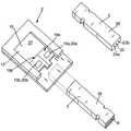
図1〜4は、分析装置2とテストエレメント3を有する、本発明による分析システム1を示す。分析装置2は、測定・評価ユニット4と、好ましくは、測定・評価ユニット4によって決定された分析結果6またはエラー信号が出力される出力ユニット5を有する。 1 to 4 show an analysis system 1 according to the invention having an
出力ユニット5は、光信号としての分析結果6を、たとえばグルコース値のような数字としてまたは種々のシンボルの形態で表示することができる。また、結果を、音響により出力することも可能である。出力ユニット5は、分析結果6に加え、たとえば正しく実行された測定の結果が、明瞭なテキストとしてまたはエラー信号のときのようにトーン信号として出力可能であること、のような別の情報を提示することができる。また、追加情報を、ユーザのために表示することもできる。 The
図1〜4に示した分析装置2は、任意で、たとえば途中の値または分析結果6のような測定結果が記憶されるメモリ7を有する。測定結果のヒストリーも、同様にして記憶される。メモリは、インタフェイスを介して、たとえば接続された装置つまりコンピュータによって読み取られる。分析結果6または別の情報は、出力ユニット5に表示することの代替としてまたはそれに追加して、インタフェイスを介して別の装置に伝送してさらに分析するまたはアーカイブに保管することもできる。 The
テストエレメント3は、試料塗布領域8と2つの分析領域9a、9bを有する。試料塗布領域8は、テストエレメント3の上部に配置されていることが好ましく、分析領域9a、9bは、テストエレメントの底部に配置されている。好ましい実施形態において、テストエレメント3は、試料塗布領域8と2つの分析領域9a、9bの間に毛細流路を有する。試料塗布領域8に塗布された体液は、毛細流路を介して分析領域9a、9bに誘導される。毛細流路は、図1〜4には示されていない。 The test element 3 has a
試料塗布領域8、および分析領域9a、9bと毛細流路の両方は、テストエレメント3の試薬システムの一部であり、その内部で、被分析物内の体液の反応が起こったとき、被分析物を特徴付ける検出可能な変化が生じ、その変化は、分析領域9a、9bで検出される。図示したように、2つの分析領域9a、9bは互いに異なっているが、重複領域を設けることも可能である。従って、両方の分析領域9a、9bは、異なる分析容積を有しており、それは、異なる大きさの容積を有することを意味する。 Both the
分析領域9a、9bで検出可能な、テストエレメント3の試薬システムの変化は、2つのアナログ測定ユニット10a、10bによって検出されるが、アナログ測定ユニット10a、10bの各々は、対応する特定の分析領域9aまたは9bの変化に比例するアナログ測定信号11aまたは11bを生成する。 Changes in the reagent system of the test element 3 that can be detected in the
測定・評価ユニット4は、2つのアナログ・デジタル変換器12a、12b(A/Dコンバータ)を有し、その各々の入力端は、特定のアナログ測定ユニット10a、10bの出力端に接続されているとともに、その入力端には、アナログ測定信号11aまたは11bが入力される。 The measurement / evaluation unit 4 includes two analog /
図1に例示した実施形態において、測定・評価ユニット3は、処理チェーンとして直列に接続されている比較器13、評価ユニット14および最終処理ユニット15を有する。 In the embodiment illustrated in FIG. 1, the measurement / evaluation unit 3 includes a
A/Dコンバータ12a、12bの入力端に入力されたアナログ信号11aまたは11bは、デジタル化されて、デジタル制御データ値17a、17bの形態のデジタル化測定信号16a、16bとしてA/Dコンバータ12a、12bから比較器13に伝送される。図1に示した実施形態において、制御データ値17a、17bは、デジタル化測定信号16a、16bと同一である。制御データ値17a、17bは、比較器13において互いに比較されて、評価ユニット14に伝送される。所望の濃度値18a、18bは、評価ユニット14の分析アルゴリズムを用いて制御データ値17a、17bから決定される。評価アルゴリズムは、制御データ値17a、17bと濃度値18a、18bの間の割当てを含む。この割当ては、たとえば評価ユニット14にテーブルの形で記憶される。 The
評価ユニット13で決定された制御データ値17a、17b間の偏差が、予め規定された値(閾値)より小さい場合、制御データ値17a、17bおよび/または制御データ値17a、17bに基づいた濃度値18a、18bの少なくとも1つが、最終処理ユニット15において有効にされる(通過が許可される)。有効化制御データ値17a、17bまたは濃度値18a、18bは、最終処理ユニット15においてさらに処理されて分析結果6になり、それは、さらなる処理のために測定・評価ユニット4の出力端から出力される。 When the deviation between the control data values 17a and 17b determined by the
両方の制御データ値17a、17bは、2つの制御データ値17a、17b間の偏差が予め規定された値より小さい場合、最終処理ユニット15によって通過を許可される(有効化されている)ことが好ましい。次いで、それらは、さらに処理されて、両方の制御データ値17a、17bの基づく所望の分析結果6に成ることが好ましい。分析結果6は、2つの制御データ値17a、17bの平均値から算出されることがとりわけ好ましい。最終処理ユニット15において、それら2つの値から算術平均または幾何平均を算出することが可能である。加重平均のような他の平均値を算出することも、可能である。分析結果6も、また、2つの濃度値18a、18bの平均値であることが好ましい。 Both
代替として、分析結果6は、最終処理ユニット15において2つの制御データ値17a、17bの低い方のまたは高い方の値から決定してもよい。ここでは制御データ値17a、17bに代えて、濃度値18a、18bを用いてもよい。 Alternatively, the analysis result 6 may be determined from the lower or higher value of the two
制御データ値17a、17b間の決定された偏差が予め規定された値を超える場合、最終処理ユニット15において通過の許可が出されないことが好ましい。代わりに、エラー信号が、生成されて出力ユニット5に伝送される。 If the determined deviation between the
図1に示した実施形態において、分析システム1は、重複構成された2つの評価チャネル19a、19bを有し、その各々は、分析領域9a、9b、アナログ測定ユニット10a、10bおよびA/Dコンバータ12a、12bを有する。 In the embodiment shown in FIG. 1, the analysis system 1 has two
図2に示した実施形態も、また、重複した2つの評価チャネル19a、19bを有する。これら評価チャネル19a、19bの各々は、分析領域9a、9bに加えて評価ユニット14a、14b、並びにアナログ測定ユニット10a、10bとA/Dコンバータ12a、12bを有する。このように、測定・評価ユニット4は、2つの評価ユニット14a、14bを有することが好ましい。制御データ値17a、17bが、評価ユニット14a、14bの各々において、評価アルゴリズムを用いてデジタル化測定信号16a、16bから生成される。評価アルゴリズムは、デジタル化測定信号16a、16bと制御データ値17a、17bの値の間の割当てを含む。 The embodiment shown in FIG. 2 also has two overlapping
制御データ値17a、17bは、濃度値18a、18bであることが好ましい。この好ましいケースにおいて、分析領域9a、9bにおいて検出した変化に対応する濃度値18a、18bが評価ユニット14a、14bに出力されるよう、評価アルゴリズムは、デジタル化測定信号16a、16bと濃度値18a、18bの値の間の割当てを含む。2つの濃度値18a、18bは、比較器13において互いに比較される。 The control data values 17a and 17b are preferably
評価ユニット14、14a、14bの評価アルゴリズムの割当ては、較正によって決められることが好ましい。較正を行なっているとき、デジタル基準測定信号が、基準濃度値の各々について生成される。その後、それらの信号と値は、たとえばテーブルなどの形で、RAM、EPROM、EEPROMなどのようなメモリに記憶される。不揮発性メモリを用いることが好ましく、メモリは、たとえば評価ユニット14、14a、14bのようなデジタル部品の1つに組み込まれる。 The assignment of the evaluation algorithms of the
濃度値を較正により予め決定しておくことによって、一方では、デジタル化測定信号の濃度値への変換を非常に簡単かつ迅速に行うことができる。他方では、バッチ固有の割当てを装置に記憶させておくことが可能になり、これにより、テストエレメントの分析領域において検出した変化と濃度値の間の異なる割当てを、(試験片または類似の物体のような)用いたテストエレメントに応じて実施することができる。 By pre-determining the density value by calibration, on the one hand, the conversion of the digitized measurement signal into the density value can be carried out very simply and quickly. On the other hand, batch-specific assignments can be stored in the instrument, which allows different assignments between detected changes and concentration values in the analysis area of the test element (for specimens or similar objects). Depending on the test element used).
デジタル評価ユニット14a、14bが重複して設けられているために、特定の動作状況または環境の下で発生し、体系的に認識不可能な(散発的エラー、ビットフリップのような)エラーが、評価ユニット14a、14bにおいて認識される。本発明による分析システム1の信頼性は、この種のエラーを捕捉することによって、ここでも高まる。 Due to the overlap of the
分析結果6は、最終処理ユニット15において濃度値18a、18bを互いに比較して決まるが、上述のように、その決定は、最終処理ユニット15によって通過を許可された濃度値18a、18bの両方または一方に基づいて行なわれる。 The analysis result 6 is determined by comparing the
図3は、2つの評価チャネル19a、19bが(重複した)評価ユニット14a、14bを有する、本発明による分析システム1の実施形態を示す。この好ましい実施形態において、測定・評価ユニット4は、分析領域9a、9b各々からの反射光を受光する2つの光受信器20a、20bを有する。光受信器20aは、分析領域9aからの反射光を受光し、光受信器20bは、分析領域9bからの反射光を受光する。光受信器20a、20bは、アナログ測定ユニット10a、10bに組み込まれている。分析装置2は、テストエレメント3の2つの分析領域9a、9bに光を照射するための光送信器21を有する。照射された光は分析領域9a、9bで反射されて、各々光受信器20aまたは20bを内蔵する2つのアナログ測定ユニット10a、10bによって受光される。アナログ測定ユニット10a、10bの各々は、対応する分析領域9a、9bからの反射光に比例するアナログ測定信号11a、11bを生成する。 FIG. 3 shows an embodiment of the analysis system 1 according to the invention in which the two
図3に示したように、光ファイバ22が、光送信器21と分析領域9a、9bの間に配置されており、それを用いて、分析領域9a、9bの少なくとも1つに光が照射されるようになっていることがとりわけ好ましい。両方の分析領域9a、9bは、光の反射が特定の分析領域9a、9bで生じるように、光が照射されることがとりわけ好ましい。光ファイバ23a、23bは、光受信器20a、20bと割り当てられた分析領域9a、9bの間に設けられていて、対応する分析領域9a、9bからの反射光を光受信器20a、20bに伝送するようになっていることが好ましい。 As shown in FIG. 3, the
次いで、光源信号により生成されたアナログ測定信号11a、11bは、図2の実施形態のように公知の方法で、分析結果6が決定されるまでさらに処理される。他の実施形態同様、この実施形態においては、制御データ値17a、17bおよび/または濃度値18a、18bの間の決定された偏差が予め規定された制限値未満の場合、制御データ値17a、17bおよび/または濃度値18a、18bだけが、通過を許可されることが好ましい。そうでない場合には、通過が阻止されるとともに、エラー信号が、生成されて出力ユニット5に出力される。 Next, the
光学的測定に基づく分析システム1の代替の実施形態においては、2つの光送信器が設けられていて、その各々が、分析領域9a、9bの1つに光を照射する。2つの評価チャネル19a、19bの各々は2つの光送信器の一方を有し、両チャネルは、まったく同じになるように構成されている。 In an alternative embodiment of the analysis system 1 based on optical measurements, two optical transmitters are provided, each illuminating one of the
光学的測定に基づく分析システムは、分析領域9a、9bにおける変化を非常に迅速かつ簡単に測定できるという利点を有する。この無接触測定は、テストエレメント3と分析装置2を空間的に分離できるという利点を有する。とりわけ、ポリマーやガラス繊維などにより形成した光導波路などの光ファイバが用いられている場合、光学的測定は、とりわけ既存の穿刺・分析複合システムと一体化することによって、大量の種類の構成を実施することを可能にする。 Analysis systems based on optical measurements have the advantage that changes in the
図4は、図2の本発明による分析システムの別の好ましい実施形態を示しており、その測定原理は、電気化学的測定に基づく。導電体24が、電圧源または電流源である電源25を2つの分析領域9a、9bに接続する。2つの導電体26a、26bが、導電体24、分析領域9a、9bおよび導電体26a、26b(戻りとして)を流れる電流をアナログ測定ユニット10aまたは10bにおいて測定できるよう、特定の分析領域9a、9bを関連付けられたアナログ測定ユニット10a、10bに接続する。勿論、測定・評価ユニット4は、先行技術におい周知の構成要素を有していてよいために、分極電圧に加えて、別のAC電圧を電源25において時間的順序で発生させることもできる。電流測定に加えてインピーダンスを測定し、それにより、液体試料についての別の情報を得ることもできる。 FIG. 4 shows another preferred embodiment of the analytical system according to the invention of FIG. 2, whose measurement principle is based on electrochemical measurements. A
代替として、2つの電源を設け、その各々を1つの導電体を用いて分析領域9a、9bの一方に接続することによって、2つの分離された回路を設けることもできる。 Alternatively, two separate circuits can be provided by providing two power supplies, each connected to one of the
図5は、同一形状に形成され、電子ユニット27に接続されている2つの評価チャネル19a、19bを有する分析装置2の好ましい実施形態を示す。電子ユニット27は、比較器13と最終処理ユニット15を有する。分析装置2は、光学的測定原理を利用しているために、アナログ測定ユニット10a、10bの各々は光受信器20a、20bを有する。 FIG. 5 shows a preferred embodiment of the
テストエレメント3は、検査棒28として実施されている。試料塗布領域8は、テストエレメント3の小さい幅の側部の1つに配置されている。3つの光ファイバが、検査棒28の内部に平行に設けられており、中央の光ファイバ22が、分析装置2から試料塗布領域8の下方に配置された分析領域9a、9b(この図では見えない)に光を伝送する。2つの外側の光ファイバ23a、23bは、分析領域9a、9bでの反射光を、分析装置2の光受信器20a、20bに送り返す。 The test element 3 is implemented as an
テストエレメント3の検査棒28としての実施は、この種の検査棒の取扱いが非常に容易で、また、ユーザからも広く受け入れてもらえるという利点を有する。同時に、試料塗布領域8と測定・評価ユニット4の明確な分離も行なわれている。それにもかかわらず、試験棒28は、分析領域9a、9bと試料塗布領域8が非常に小さいサイズになるよう実施されるために、100nl以下という非常に少量の血液で動作する。液体の搬送流路は非常に短い。光を用いる光伝送であるために、実際の測定部を、試料塗布領域8から離れた装置2の位置に組み込むことができる。 The implementation of the test element 3 as a
1 分析システム
2 分析装置
3 テストエレメント
4 測定および評価ユニット
5 出力ユニット
6 分析結果
7 メモリ
8 塗布領域
9a、9b 分析領域
10a、10b アナログ測定ユニット
11a、11b アナログ測定信号
12a、12b アナログ−デジタル変換器
13 比較ユニット
14 評価ユニット
15 最終処理ユニット
16a、16b デジタル化測定信号
17a、17b 制御データ値
18a、18b 濃度値
19a、19b 評価チャネル
20a、20b 光受信器
21 光送信器
22、23a、23b 光ファイバ
24、26a、26b 導電体
25 電源
27 電気ユニット
28 検査棒DESCRIPTION OF SYMBOLS 1
Claims (15)
Translated fromJapanese被分析物との反応により所望の分析結果を特徴付ける検出可能な変化を生じる試薬システム、試料塗布領域(8)、および2つの分析領域(9a、9b)を備えるテストエレメント(3)と、
測定・評価ユニット(4)を備える分析装置(2)とを有し、
前記分析装置(2)は、
前記分析領域(9a、9b)の1つに対応するアナログ測定信号(11a、11b)を各々が生成する2つのアナログ測定ユニット(10a、10b)と、
前記アナログ測定信号(11a、11b)をデジタル化する2つのアナログ・デジタル変換器(12a、12b)と、
制御データ値(17a、17b)をデジタル化測定信号(16a、16b)に基づいて比較するための比較器(13)と、
前記デジタル化測定信号(16a、16b)の前記制御データ値(17a、17b)間の決定された偏差が予め規定された値より小さい場合、前記所望の分析結果(6)を得るために、前記制御データ値(17a、17b)の少なくとも1つがさらなる処理のために通過を許可される最終処理ユニット(15)とを有することを特徴とする分析システム。In an analysis system for measuring an analyte in a body fluid,
A test element (3) comprising a reagent system, a sample application region (8), and two analysis regions (9a, 9b) that produce a detectable change that characterizes a desired analysis result by reaction with an analyte;
And an analyzer (2) provided with a measurement / evaluation unit (4),
The analyzer (2)
Two analog measurement units (10a, 10b) each generating an analog measurement signal (11a, 11b) corresponding to one of the analysis regions (9a, 9b);
Two analog-to-digital converters (12a, 12b) for digitizing the analog measurement signals (11a, 11b);
A comparator (13) for comparing the control data values (17a, 17b) based on the digitized measurement signals (16a, 16b);
If the determined deviation between the control data values (17a, 17b) of the digitized measurement signal (16a, 16b) is less than a predefined value, in order to obtain the desired analysis result (6) Analysis system, characterized in that it has a final processing unit (15) in which at least one of the control data values (17a, 17b) is allowed to pass for further processing.
前記測定・評価ユニット(4)は、1つの分析領域(9a、9b)からの光を各々受光するための2つの光受信器(20a、20b)を有し、
さらに、前記2つのアナログ測定ユニット(10a、10b)の各々においてアナログ測定信号(11a、11b)が生成され、前記アナログ測定信号(11a、11b)は、前記分析領域(9a、9b)での反射光に比例することを特徴とする請求項1〜5のいずれか1項に記載の分析システム。The analyzer (2) has an optical transmitter (21) for irradiating the analysis region (9a, 9b) with light.
The measurement / evaluation unit (4) has two optical receivers (20a, 20b) for receiving light from one analysis region (9a, 9b),
Furthermore, an analog measurement signal (11a, 11b) is generated in each of the two analog measurement units (10a, 10b), and the analog measurement signal (11a, 11b) is reflected from the analysis region (9a, 9b). It is proportional to light, The analysis system of any one of Claims 1-5 characterized by the above-mentioned.
また、前記分析領域(9a、9b)での反射光が前記光受信器(20a、20b)に伝送されるよう、各々の光受信器(20a、20b)と各々の分析領域(9a、9b)との間に光ファイバ(23a、23b)が配置されていることを特徴とする請求項6記載の分析システム。An optical fiber (22) is disposed between the optical transmitter (21) and the analysis region (9a, 9b) so that at least one of the analysis regions (9a, 9b) is irradiated with light,
Also, each optical receiver (20a, 20b) and each analysis region (9a, 9b) are transmitted so that the reflected light from the analysis region (9a, 9b) is transmitted to the optical receiver (20a, 20b). An analysis system according to claim 6, characterized in that optical fibers (23a, 23b) are arranged between the two.
Applications Claiming Priority (2)
| Application Number | Priority Date | Filing Date | Title |
|---|---|---|---|
| EP07018674.7 | 2007-09-22 | ||
| EP07018674AEP2040072B1 (en) | 2007-09-22 | 2007-09-22 | Analysis system for measuring the concentration of an analyte in a bodily fluid |
Publications (2)
| Publication Number | Publication Date |
|---|---|
| JP2009075112Atrue JP2009075112A (en) | 2009-04-09 |
| JP5259318B2 JP5259318B2 (en) | 2013-08-07 |
Family
ID=38891055
Family Applications (1)
| Application Number | Title | Priority Date | Filing Date |
|---|---|---|---|
| JP2008241193AExpired - Fee RelatedJP5259318B2 (en) | 2007-09-22 | 2008-09-19 | Analytical system for measuring analytes in body fluids |
Country Status (7)
| Country | Link |
|---|---|
| US (1) | US8280642B2 (en) |
| EP (1) | EP2040072B1 (en) |
| JP (1) | JP5259318B2 (en) |
| CN (1) | CN101393198B (en) |
| CA (1) | CA2639731C (en) |
| ES (1) | ES2400966T3 (en) |
| PL (1) | PL2040072T3 (en) |
Families Citing this family (11)
| Publication number | Priority date | Publication date | Assignee | Title |
|---|---|---|---|---|
| US9023063B2 (en)* | 2008-04-17 | 2015-05-05 | Apollo Endosurgery, Inc. | Implantable access port device having a safety cap |
| CN103140755B (en) | 2010-07-22 | 2016-03-16 | 哈希公司 | For the lab on A Chip of alkalinity analyzing |
| EP2769227B1 (en)* | 2011-10-17 | 2016-07-27 | Roche Diagnostics GmbH | Troponin and bnp based diagnosis of risk patients and cause of stroke |
| US9180449B2 (en) | 2012-06-12 | 2015-11-10 | Hach Company | Mobile water analysis |
| USD768872S1 (en) | 2012-12-12 | 2016-10-11 | Hach Company | Cuvette for a water analysis instrument |
| HUE034313T2 (en)* | 2012-12-20 | 2018-02-28 | Hoffmann La Roche | Methods for evaluating medical measurement curves |
| WO2017089297A1 (en)* | 2015-11-23 | 2017-06-01 | Roche Diabetes Care Gmbh | Method and apparatus for determining the concentration of an analyte in a body fluid |
| CN105403691B (en)* | 2016-01-01 | 2017-08-18 | 赛奥生物科技(青岛)有限公司 | A kind of Blood Kit analysis system |
| CN106990232B (en)* | 2016-01-01 | 2019-05-28 | 海南欣泰康医药科技有限公司 | Blood Kit analysis system and analysis method |
| EP3195795B1 (en)* | 2016-01-19 | 2023-08-23 | Roche Diabetes Care GmbH | Sensor assembly and method for detecting at least one analyte in a body fluid |
| CN114778629B (en)* | 2022-04-28 | 2023-10-20 | 孟栋栋 | Clinical blood drawing detection device for medical endocrinology department |
Citations (12)
| Publication number | Priority date | Publication date | Assignee | Title |
|---|---|---|---|---|
| JPH01291153A (en)* | 1988-05-18 | 1989-11-22 | Matsushita Electric Ind Co Ltd | Biosensor |
| JPH04264246A (en)* | 1991-02-19 | 1992-09-21 | Matsushita Electric Ind Co Ltd | biosensor |
| JPH05340915A (en)* | 1991-10-18 | 1993-12-24 | Matsushita Electric Ind Co Ltd | Biosensor and measuring method using the same |
| JPH0767698A (en)* | 1986-08-13 | 1995-03-14 | Lifescan Inc | Reagent test strip for measuring subject for analysis |
| JPH1073535A (en)* | 1996-07-16 | 1998-03-17 | Boehringer Mannheim Gmbh | Analyzer with means for detecting micro quantity of sample |
| JP2001208715A (en)* | 1999-11-15 | 2001-08-03 | Matsushita Electric Ind Co Ltd | Biosensor, quantitative method and quantitative device using the same |
| JP2003526785A (en)* | 2000-03-08 | 2003-09-09 | インバネス・メディカル・リミテッド | Method and apparatus for measuring substance in liquid |
| JP2004117342A (en)* | 2002-09-03 | 2004-04-15 | Matsushita Electric Ind Co Ltd | Biosensor and measurement method using the same |
| JP2007108104A (en)* | 2005-10-17 | 2007-04-26 | Sumitomo Electric Ind Ltd | Sensor chip and manufacturing method thereof |
| JP2007524094A (en)* | 2004-02-16 | 2007-08-23 | ピー エー コンサルティング サービシーズ リミテッド | Analyte testing apparatus and method |
| JP2007524818A (en)* | 2003-06-20 | 2007-08-30 | エフ ホフマン−ラ ロッシュ アクチェン ゲゼルシャフト | Biosensor with multi-stage electrical functionality |
| JP2008509406A (en)* | 2004-08-13 | 2008-03-27 | エゴメディカル テクノロジーズ アクチエンゲゼルシャフト | Analyte testing system for quantifying analyte concentration in physiological or aqueous liquids |
Family Cites Families (10)
| Publication number | Priority date | Publication date | Assignee | Title |
|---|---|---|---|---|
| DE2828232C2 (en)* | 1978-06-28 | 1986-04-17 | Kernforschungsanlage Jülich GmbH, 5170 Jülich | Device for determining the dielectric breakthrough and the size of particles having a membrane as an envelope |
| US4775237A (en)* | 1987-03-16 | 1988-10-04 | Innovative Medical Systems Corp. | Electro-optical detection system |
| US5264103A (en) | 1991-10-18 | 1993-11-23 | Matsushita Electric Industrial Co., Ltd. | Biosensor and a method for measuring a concentration of a substrate in a sample |
| IL107396A (en)* | 1992-11-09 | 1997-02-18 | Boehringer Mannheim Gmbh | Method and apparatus for analytical determination of glucose in a biological matrix |
| US7494816B2 (en)* | 1997-12-22 | 2009-02-24 | Roche Diagnostic Operations, Inc. | System and method for determining a temperature during analyte measurement |
| WO1999058050A1 (en)* | 1998-05-13 | 1999-11-18 | Cygnus, Inc. | Signal processing for measurement of physiological analytes |
| US7806886B2 (en)* | 1999-06-03 | 2010-10-05 | Medtronic Minimed, Inc. | Apparatus and method for controlling insulin infusion with state variable feedback |
| US20020016535A1 (en)* | 2000-01-28 | 2002-02-07 | Martin W. Blake | Subcutaneous glucose measurement device |
| ATE507766T1 (en)* | 2002-03-22 | 2011-05-15 | Animas Technologies Llc | PERFORMANCE IMPROVEMENT OF AN ANALYTE MONITORING DEVICE |
| JP4165330B2 (en)* | 2003-04-16 | 2008-10-15 | 株式会社デンソー | Air conditioner |
- 2007
- 2007-09-22PLPL07018674Tpatent/PL2040072T3/enunknown
- 2007-09-22ESES07018674Tpatent/ES2400966T3/enactiveActive
- 2007-09-22EPEP07018674Apatent/EP2040072B1/ennot_activeNot-in-force
- 2008
- 2008-09-19USUS12/233,889patent/US8280642B2/ennot_activeExpired - Fee Related
- 2008-09-19JPJP2008241193Apatent/JP5259318B2/ennot_activeExpired - Fee Related
- 2008-09-19CACA2639731Apatent/CA2639731C/ennot_activeExpired - Fee Related
- 2008-09-22CNCN200810215254.XApatent/CN101393198B/ennot_activeExpired - Fee Related
Patent Citations (12)
| Publication number | Priority date | Publication date | Assignee | Title |
|---|---|---|---|---|
| JPH0767698A (en)* | 1986-08-13 | 1995-03-14 | Lifescan Inc | Reagent test strip for measuring subject for analysis |
| JPH01291153A (en)* | 1988-05-18 | 1989-11-22 | Matsushita Electric Ind Co Ltd | Biosensor |
| JPH04264246A (en)* | 1991-02-19 | 1992-09-21 | Matsushita Electric Ind Co Ltd | biosensor |
| JPH05340915A (en)* | 1991-10-18 | 1993-12-24 | Matsushita Electric Ind Co Ltd | Biosensor and measuring method using the same |
| JPH1073535A (en)* | 1996-07-16 | 1998-03-17 | Boehringer Mannheim Gmbh | Analyzer with means for detecting micro quantity of sample |
| JP2001208715A (en)* | 1999-11-15 | 2001-08-03 | Matsushita Electric Ind Co Ltd | Biosensor, quantitative method and quantitative device using the same |
| JP2003526785A (en)* | 2000-03-08 | 2003-09-09 | インバネス・メディカル・リミテッド | Method and apparatus for measuring substance in liquid |
| JP2004117342A (en)* | 2002-09-03 | 2004-04-15 | Matsushita Electric Ind Co Ltd | Biosensor and measurement method using the same |
| JP2007524818A (en)* | 2003-06-20 | 2007-08-30 | エフ ホフマン−ラ ロッシュ アクチェン ゲゼルシャフト | Biosensor with multi-stage electrical functionality |
| JP2007524094A (en)* | 2004-02-16 | 2007-08-23 | ピー エー コンサルティング サービシーズ リミテッド | Analyte testing apparatus and method |
| JP2008509406A (en)* | 2004-08-13 | 2008-03-27 | エゴメディカル テクノロジーズ アクチエンゲゼルシャフト | Analyte testing system for quantifying analyte concentration in physiological or aqueous liquids |
| JP2007108104A (en)* | 2005-10-17 | 2007-04-26 | Sumitomo Electric Ind Ltd | Sensor chip and manufacturing method thereof |
Also Published As
| Publication number | Publication date |
|---|---|
| CA2639731C (en) | 2011-07-05 |
| EP2040072A1 (en) | 2009-03-25 |
| PL2040072T3 (en) | 2013-06-28 |
| CN101393198A (en) | 2009-03-25 |
| HK1132325A1 (en) | 2010-02-19 |
| CN101393198B (en) | 2014-06-25 |
| EP2040072B1 (en) | 2013-01-02 |
| US20090082973A1 (en) | 2009-03-26 |
| CA2639731A1 (en) | 2009-03-22 |
| ES2400966T3 (en) | 2013-04-15 |
| JP5259318B2 (en) | 2013-08-07 |
| US8280642B2 (en) | 2012-10-02 |
Similar Documents
| Publication | Publication Date | Title |
|---|---|---|
| JP5259318B2 (en) | Analytical system for measuring analytes in body fluids | |
| US5781024A (en) | Instrument performance verification system | |
| CN108318560B (en) | Portable microelectrode method blood detector and detection method thereof | |
| Fernandes et al. | A complete blood typing device for automatic agglutination detection based on absorption spectrophotometry | |
| CA2603685A1 (en) | Method for detecting erroneous measurement results obtained with ion selective electrodes | |
| US7630084B2 (en) | System and method for acquiring and evaluating optical signals | |
| US12072310B2 (en) | Dielectric sensing to characterize properties of a sample under test | |
| US8481329B2 (en) | Analysis system for the photometric determination of an analyte in a body fluid | |
| CN105403691B (en) | A kind of Blood Kit analysis system | |
| KR20210011853A (en) | Diabetic measuring urinal and system | |
| HK1132325B (en) | Analysis system for determining an analyte in a body fluid | |
| CN102033061A (en) | Microchip blood analyzer | |
| KR101009284B1 (en) | Multifunction portable diagnostic system | |
| EP1906179A1 (en) | Method for detecting erroneous measurement results obtained with ion selective electrodes | |
| CN105388276B (en) | A blood reagent analysis system and analysis method | |
| EP1906180B1 (en) | Method for detecting erroneous measurement results obtained with ion selective electrodes | |
| Gries et al. | The determination of detection and quantitation limits in human biomonitoring | |
| CA2295001C (en) | Instrument performance verification system | |
| WO1994001761A1 (en) | A diagnostic electrode for evaluating circuitry of an analyzer | |
| JPS60161546A (en) | Air bubble detection device | |
| Oliveira et al. | Point-of-care testing device for diabetes mellitus and renal function analysis of biological fluids | |
| EP3308161A1 (en) | A biochemical analytical technique | |
| HK1106825A (en) | Method for the audible output of a piece of information in an analysis system | |
| HU180877B (en) | Arrangement for detecting characteristics of liquids and/or gases,in particular,hemoglobin concentration of blood | |
| HK1115634A (en) | Method for detecting erroneous measurement results obtained with ion selective electrodes |
Legal Events
| Date | Code | Title | Description |
|---|---|---|---|
| RD03 | Notification of appointment of power of attorney | Free format text:JAPANESE INTERMEDIATE CODE: A7423 Effective date:20100525 | |
| A621 | Written request for application examination | Free format text:JAPANESE INTERMEDIATE CODE: A621 Effective date:20110506 | |
| A977 | Report on retrieval | Free format text:JAPANESE INTERMEDIATE CODE: A971007 Effective date:20120821 | |
| A131 | Notification of reasons for refusal | Free format text:JAPANESE INTERMEDIATE CODE: A131 Effective date:20120828 | |
| A521 | Written amendment | Free format text:JAPANESE INTERMEDIATE CODE: A523 Effective date:20121127 | |
| TRDD | Decision of grant or rejection written | ||
| A01 | Written decision to grant a patent or to grant a registration (utility model) | Free format text:JAPANESE INTERMEDIATE CODE: A01 Effective date:20130402 | |
| A61 | First payment of annual fees (during grant procedure) | Free format text:JAPANESE INTERMEDIATE CODE: A61 Effective date:20130424 | |
| FPAY | Renewal fee payment (event date is renewal date of database) | Free format text:PAYMENT UNTIL: 20160502 Year of fee payment:3 | |
| R150 | Certificate of patent or registration of utility model | Free format text:JAPANESE INTERMEDIATE CODE: R150 | |
| R250 | Receipt of annual fees | Free format text:JAPANESE INTERMEDIATE CODE: R250 | |
| R250 | Receipt of annual fees | Free format text:JAPANESE INTERMEDIATE CODE: R250 | |
| LAPS | Cancellation because of no payment of annual fees |